EP3747706A1 - Fahrzeuggesamtsicherheitsleistungsanwendung und -verfahren mit verwendung von unfallkonfigurationsinformationen - Google Patents
Fahrzeuggesamtsicherheitsleistungsanwendung und -verfahren mit verwendung von unfallkonfigurationsinformationen Download PDFInfo
- Publication number
- EP3747706A1 EP3747706A1 EP20177784.4A EP20177784A EP3747706A1 EP 3747706 A1 EP3747706 A1 EP 3747706A1 EP 20177784 A EP20177784 A EP 20177784A EP 3747706 A1 EP3747706 A1 EP 3747706A1
- Authority
- EP
- European Patent Office
- Prior art keywords
- vehicle
- crash
- impact event
- input
- occupant
- Prior art date
- Legal status (The legal status is an assumption and is not a legal conclusion. Google has not performed a legal analysis and makes no representation as to the accuracy of the status listed.)
- Granted
Links
Images







Classifications
-
- B—PERFORMING OPERATIONS; TRANSPORTING
- B60—VEHICLES IN GENERAL
- B60W—CONJOINT CONTROL OF VEHICLE SUB-UNITS OF DIFFERENT TYPE OR DIFFERENT FUNCTION; CONTROL SYSTEMS SPECIALLY ADAPTED FOR HYBRID VEHICLES; ROAD VEHICLE DRIVE CONTROL SYSTEMS FOR PURPOSES NOT RELATED TO THE CONTROL OF A PARTICULAR SUB-UNIT
- B60W30/00—Purposes of road vehicle drive control systems not related to the control of a particular sub-unit, e.g. of systems using conjoint control of vehicle sub-units
- B60W30/08—Active safety systems predicting or avoiding probable or impending collision or attempting to minimise its consequences
- B60W30/09—Taking automatic action to avoid collision, e.g. braking and steering
-
- G—PHYSICS
- G06—COMPUTING OR CALCULATING; COUNTING
- G06F—ELECTRIC DIGITAL DATA PROCESSING
- G06F30/00—Computer-aided design [CAD]
- G06F30/10—Geometric CAD
- G06F30/15—Vehicle, aircraft or watercraft design
-
- B—PERFORMING OPERATIONS; TRANSPORTING
- B60—VEHICLES IN GENERAL
- B60R—VEHICLES, VEHICLE FITTINGS, OR VEHICLE PARTS, NOT OTHERWISE PROVIDED FOR
- B60R21/00—Arrangements or fittings on vehicles for protecting or preventing injuries to occupants or pedestrians in case of accidents or other traffic risks
- B60R21/01—Electrical circuits for triggering passive safety arrangements, e.g. airbags, safety belt tighteners, in case of vehicle accidents or impending vehicle accidents
- B60R21/013—Electrical circuits for triggering passive safety arrangements, e.g. airbags, safety belt tighteners, in case of vehicle accidents or impending vehicle accidents including means for detecting collisions, impending collisions or roll-over
-
- B—PERFORMING OPERATIONS; TRANSPORTING
- B60—VEHICLES IN GENERAL
- B60W—CONJOINT CONTROL OF VEHICLE SUB-UNITS OF DIFFERENT TYPE OR DIFFERENT FUNCTION; CONTROL SYSTEMS SPECIALLY ADAPTED FOR HYBRID VEHICLES; ROAD VEHICLE DRIVE CONTROL SYSTEMS FOR PURPOSES NOT RELATED TO THE CONTROL OF A PARTICULAR SUB-UNIT
- B60W30/00—Purposes of road vehicle drive control systems not related to the control of a particular sub-unit, e.g. of systems using conjoint control of vehicle sub-units
- B60W30/08—Active safety systems predicting or avoiding probable or impending collision or attempting to minimise its consequences
-
- B—PERFORMING OPERATIONS; TRANSPORTING
- B60—VEHICLES IN GENERAL
- B60W—CONJOINT CONTROL OF VEHICLE SUB-UNITS OF DIFFERENT TYPE OR DIFFERENT FUNCTION; CONTROL SYSTEMS SPECIALLY ADAPTED FOR HYBRID VEHICLES; ROAD VEHICLE DRIVE CONTROL SYSTEMS FOR PURPOSES NOT RELATED TO THE CONTROL OF A PARTICULAR SUB-UNIT
- B60W40/00—Estimation or calculation of non-directly measurable driving parameters for road vehicle drive control systems not related to the control of a particular sub unit, e.g. by using mathematical models
-
- B—PERFORMING OPERATIONS; TRANSPORTING
- B60—VEHICLES IN GENERAL
- B60R—VEHICLES, VEHICLE FITTINGS, OR VEHICLE PARTS, NOT OTHERWISE PROVIDED FOR
- B60R21/00—Arrangements or fittings on vehicles for protecting or preventing injuries to occupants or pedestrians in case of accidents or other traffic risks
- B60R21/01—Electrical circuits for triggering passive safety arrangements, e.g. airbags, safety belt tighteners, in case of vehicle accidents or impending vehicle accidents
- B60R21/013—Electrical circuits for triggering passive safety arrangements, e.g. airbags, safety belt tighteners, in case of vehicle accidents or impending vehicle accidents including means for detecting collisions, impending collisions or roll-over
- B60R2021/01315—Electrical circuits for triggering passive safety arrangements, e.g. airbags, safety belt tighteners, in case of vehicle accidents or impending vehicle accidents including means for detecting collisions, impending collisions or roll-over monitoring occupant displacement
-
- B—PERFORMING OPERATIONS; TRANSPORTING
- B60—VEHICLES IN GENERAL
- B60W—CONJOINT CONTROL OF VEHICLE SUB-UNITS OF DIFFERENT TYPE OR DIFFERENT FUNCTION; CONTROL SYSTEMS SPECIALLY ADAPTED FOR HYBRID VEHICLES; ROAD VEHICLE DRIVE CONTROL SYSTEMS FOR PURPOSES NOT RELATED TO THE CONTROL OF A PARTICULAR SUB-UNIT
- B60W2520/00—Input parameters relating to overall vehicle dynamics
- B60W2520/10—Longitudinal speed
-
- B—PERFORMING OPERATIONS; TRANSPORTING
- B60—VEHICLES IN GENERAL
- B60W—CONJOINT CONTROL OF VEHICLE SUB-UNITS OF DIFFERENT TYPE OR DIFFERENT FUNCTION; CONTROL SYSTEMS SPECIALLY ADAPTED FOR HYBRID VEHICLES; ROAD VEHICLE DRIVE CONTROL SYSTEMS FOR PURPOSES NOT RELATED TO THE CONTROL OF A PARTICULAR SUB-UNIT
- B60W2520/00—Input parameters relating to overall vehicle dynamics
- B60W2520/12—Lateral speed
-
- B—PERFORMING OPERATIONS; TRANSPORTING
- B60—VEHICLES IN GENERAL
- B60W—CONJOINT CONTROL OF VEHICLE SUB-UNITS OF DIFFERENT TYPE OR DIFFERENT FUNCTION; CONTROL SYSTEMS SPECIALLY ADAPTED FOR HYBRID VEHICLES; ROAD VEHICLE DRIVE CONTROL SYSTEMS FOR PURPOSES NOT RELATED TO THE CONTROL OF A PARTICULAR SUB-UNIT
- B60W2556/00—Input parameters relating to data
- B60W2556/10—Historical data
-
- G—PHYSICS
- G06—COMPUTING OR CALCULATING; COUNTING
- G06F—ELECTRIC DIGITAL DATA PROCESSING
- G06F2119/00—Details relating to the type or aim of the analysis or the optimisation
- G06F2119/14—Force analysis or force optimisation, e.g. static or dynamic forces
Definitions
- the present disclosure relates generally to the automotive field. More specifically, the present disclosure relates to a vehicle total safety performance application and method utilizing crash configuration information.
- A-HBMs active human body models
- the overall aim of the present disclosure is to create a CAE methodology for predicting the combined safety performance from collision avoidance systems (e.g. autonomous emergency braking (AEB)) as well as systems for injury prevention (e.g. seatbelts and airbags).
- AEB autonomous emergency braking
- Specific aims are to establish two important elements in this simulation methodology.
- the first element concerns real-world data, and the transfer of real-world pre-crash situations into crash configurations to be used in crash simulations providing insight into occupant protection.
- the second considers the human occupant, enabling computationally efficient prediction of position transfer between pre-crash situations and crashes.
- This background provides an exemplary context and environment only for the methodologies of the present disclosure, and it will be readily apparent to those of ordinary skill in the art that the methodologies of the present disclosure may be practiced in other contexts and environments as well.
- the present disclosure provides a method, including: receiving first input related to expected states of a vehicle and another vehicle or object at impact event initiation with positions, orientations, and velocities as parameters used for impact event evaluation; receiving second input related to expected vehicle occupant position and position transfer during a pre-impact event maneuver; and simulating an impact event involving the vehicle and the another vehicle or object using both the first input and the second input to quantify the performance of a safety system of the vehicle with a combined effect from a collision avoidance feature and an injury prevention feature.
- the method further includes filtering out a case where a vehicle occupant pre-crash position excursion is expected to exceed a predetermined threshold.
- the first input includes real-world pre-impact event data related to paths, velocities, and surroundings in time history data format.
- the first input also includes output from a computer aided engineering simulation of a Baseline impact event without a collision avoidance system implemented and a Treatment impact event with the collision avoidance system implemented.
- the first input further includes parametric crash configuration data related to the vehicle and the another vehicle or object at the impact event initiation.
- the second input includes a simplified occupant kinetics model. Simulating the impact event includes simulating effects of a pre-crash phase and the impact event using vehicle occupant and interior models using an active human body model. Simulating the impact event also includes simulating the vehicle structural effects of the impact event using a structural simulation.
- the present disclosure provides a non-transitory computer readable medium including combined safety system performance simulation and evaluation instructions stored in a memory and executed by a processor to carry out the steps, including: receiving first input related to expected states of a vehicle and another vehicle or object at impact event initiation with positions, orientations, and velocities as parameters used for impact event evaluation; receiving second input related to expected vehicle occupant position and position transfer during a pre-impact event maneuver; and simulating an impact event involving the vehicle and the another vehicle or object using both the first input and the second input to quantify the performance of a safety system of the vehicle with a combined effect from a collision avoidance feature and an injury prevention feature.
- the steps further include filtering out a case where a vehicle occupant pre-crash position excursion is expected to exceed a predetermined threshold.
- the first input includes real-world pre-impact event data related to paths, velocities, and surroundings in time history data format.
- the first input also includes output from a computer aided engineering simulation of a Baseline impact event without a collision avoidance system implemented and a Treatment impact event with the collision avoidance system implemented.
- the first input further includes parametric crash configuration data related to the vehicle and the another vehicle or object at the impact event initiation.
- the second input includes a simplified occupant kinetics model. Simulating the impact event includes the step of simulating effects of a pre-crash phase and the impact event using vehicle occupant and interior models using an active human body model. Simulating the impact event also includes the step of simulating the vehicle structural effects of the impact event using a structural simulation.
- the present disclosure provides a system, including: memory storing vehicle simulation instructions executed by a processor for receiving first input related to expected states of a vehicle and another vehicle or object at impact event initiation with positions, orientations, and velocities as parameters used for impact event evaluation; the memory storing vehicle occupant simulation instructions executed by the processor for receiving second input related to expected vehicle occupant position and position transfer during a pre-impact event maneuver; and the memory storing combined impact event simulation instructions executed by the processor for simulating an impact event involving the vehicle and the another vehicle or object using both the first input and the second input to quantify the performance of a safety system of the vehicle with a combined effect from a collision avoidance feature and an injury prevention feature.
- the system also includes the memory storing focus case selection instructions executed by the processor for filtering out a case where a vehicle occupant pre-crash position excursion is expected to exceed a predetermined threshold.
- the first input includes: real-world pre-impact event data related to paths, velocities, and surroundings in time history data format, output from a computer aided engineering simulation of a Baseline impact event without a collision avoidance system implemented and a Treatment impact event with the collision avoidance system implemented, and parametric crash configuration data related to the vehicle and the another vehicle or object at the impact event initiation
- the second input includes: a simplified occupant kinetics model. Simulating the impact event includes simulating effects of a pre-crash phase and the impact event using vehicle occupant and interior models using an active human body model and simulating the vehicle structural effects of the impact event using a structural simulation.
- the present disclosure aims at establishing a computer simulation methodology including two important elements for assessing this combined effect.
- the first element describes the states of the involved vehicles or objects at crash initiation regarding positions, orientations, and velocities as parameters used for crash evaluation.
- the second element focuses on the vehicle occupant, enabling computationally efficient prediction of occupant position transfer during pre-crash maneuvers.
- Real-world data from a traffic accident database is used as the basis for pre-crash simulations involving two vehicles, with and without a conceptual autonomous emergency braking (AEB) function, for example.
- AEB autonomous emergency braking
- the crash configuration is identified.
- a SOCKIMO is developed and applied to these remaining crashes, supporting the selection of crash situations to be analyzed in detail.
- the SAFER HBM is used for simulation of the occupant response, providing information on pre-crash kinematics, as well as the occupant crash response.
- the PARCC definition can be used as a link between pre-crash and crash simulation tools, as well as for illustrating sets of real-world accident data and how these change based on maneuvers preceding a crash.
- SOCKIMO results demonstrate occupant kinematics similar to those of volunteers, and the subsequent simulations using the SAFER HBM show considerable changes in occupant crash response based on pre-crash vehicle kinematics.
- the PARCC definition can also be applied to collision objects, such as trucks or vulnerable road users.
- the developed SOCKIMO can be used to filter out cases from large crash data sets to be further analyzed with detailed models, FE A-HBMs. By applying the more detailed HBMs, the effects of avoidance maneuvers on occupant kinematics relevant for injury prediction can be evaluated. This approach would not be possible using simplified occupant models only (due to the lack of details) or by using detailed models only (due to the large simulation effort).
- the presented methodology for estimating combined safety performance can be used for transferring output from pre-crash simulations to input for crash simulations.
- the feasibility of combining the individual elements of this methodology is demonstrated in an example case where AEB leads to a large change in the crash configuration and is predicted to introduce substantial occupant pre-crash excursion.
- the present A-HBM tool is able to cover the complete sequence from pre-crash maneuvers to crash in one single simulation.
- a methodology is presented for estimating the total safety performance based on CAE tools, i.e. how the effects of countermeasures aimed at injury prevention before and during a crash can be described using computer models in order to summarize these effects for larger sets of traffic scenarios. This is followed by one specific example case which is chosen to demonstrate and further explain the selection process and the transfer of data between CAE tools.
- the overall methodology 10 contains seven elements, as illustrated in Figure 1 . It has its basis in real-world data, and provides output of vehicle occupant response during the complete sequence of events covering both pre-crash and crash phases.
- the process starts with identifying real-world traffic situation datasets relevant for the research question at hand, as illustrated by element 1 and ends with the output that is given from occupant pre-crash and crash simulation in element 7.
- Each of these and intermediate elements are further described below.
- the SAFER HBM 26, Figure 2 has active musculature implemented using Hill-type beam muscle elements controlled by feedback controllers.
- the most recent update of the active muscle control includes an omnidirectional lumbar and cervical spine controller, which enables modelling of both vehicle driver and passenger reflexive and postural responses in pre-crash scenarios.
- the vehicle interior used in this study consists of a rigid sled model representing a passenger vehicle body structure where deformable models of the interior components, such as seat, steering wheel, instrument panel, airbags, and seat belts, are included, Figure 2 .
- the first phase 28 is for HBM 26 stabilization needed for the model to find equilibrium under gravity loading and with active muscles.
- this phase 28 which lasts for 300 ms, the rigid sled is stationary.
- phase 30 of pre-crash vehicle kinematics (PCVK) the maneuver from the CA-CAE pre-crash simulation 14 ( Figure 1 ) is given as prescribed motion to the sled.
- the PCVK 30 includes three degrees of freedom (DOF): longitudinal and lateral acceleration of the vehicle, as well as yaw velocity.
- the PCVK phase 30 has a duration of 1000 ms when included.
- a crash pulse lasting 200 ms recorded from the FE structural crash simulation 24 ( Figure 1 ) is applied to the rigid sled model using a complete 6 DOF description, i.e. accelerations in all three local directions, as well as rotational velocities around the same axes.
- the SAFER HBM model 26 ( Figure 2 ) is used to estimate driver kinematics during the PCVK 30 and the crash 32.
- Parametric Crash Configuration - PARCC (element 3) 16 ( Figure 1 ).
- the PARCC 16 is proposed.
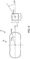
- this approach 34 illustrated in Figures 4-6 , the first point of contact (FPOC) between two colliding objects is used (for visualization, two identical passenger vehicles are used here).
- This part of the crash configuration is to be interpreted as a birds-eye view (BEV) of the physical appearance of the two objects when first contact occurs.
- the host vehicle 36 serves as the reference system according to the Society of Automotive Engineers (SAE), where the FPOC is described.
- the heading direction is defined to coincide with the longitudinal axis of each vehicle, even though in the generalized case the velocity vector at the time of collision may differ from the heading direction in the crash configuration.
- HCPO host center point
- HCPL host center plane
- FPOC FPOC
- the location of the FPOC on the opponent vehicle 38 is defined as the original opponent collision point angle (called OCPA 0 ) using the local reference system of the opponent vehicle 38.
- OCPA 0 original opponent collision point angle
- the heading direction of the opponent vehicle 38 is defined relative to the heading direction of the host vehicle 36. This angle is called the opponent yaw angle (OYA), as indicated in Figure 5 .
- the description of the FPOC in terms of HCPA 0 and OCPA 0 is dependent on the vehicle width-to-length ratio. However, a more universal way of describing the angles is sought, therefore the vehicle dimensions including the FPOC are scaled to a square unit vehicle as described in Figure 6 . In this way, a transformed host collision point angle (HCPA) is defined for further use. The same procedure is applied to obtain the transformed opponent collision point angle (OCPA).
- HCPA transformed host collision point angle
- the proposed method for describing crash configuration can be used as a tool for visualizing larger sets of crash configuration data to be considered in the development of safety systems.
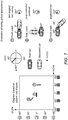
- Figure 7 three examples of vehicle-to-vehicle collisions are used to explain how a crash configuration diagram can be created.
- Figure 7 shows how the transformed host and opponent collision point angles HCPA and OCPA combined with the opponent yaw angle OYA for the impact direction gives a graphic illustration of each crash configuration directly in the diagram.
- Figure 8 provides a graphical representation of how the simplified model 40 is implemented.
- Rigid bodies are assumed between the head center of gravity 42, first thoracic vertebrae (T1) 44, sternum 46, and the hip joint 48. These are positions that were all featured as tracking points in available volunteer data, later used for tuning and validating the model 40.
- a lower inverted pendulum is based in the occupant hip joint location 48 and includes a point representing the sternum 46.
- a hinge joint is defined at the upper end of the lower pendulum, corresponding to the center of the T1 vertebra 44. This hinge joint attaches to the upper pendulum that ends in the head center of gravity 42.
- the upper pendulum is constrained to movement in the plane initially defined by the hip joint 48, T1 44, and head center of gravity 42. Since this plane is updated corresponding to the displacement of the lower pendulum, the head center of gravity 42 is free to move out of the initial sagittal plane.
- the seat back 50 was modeled as a contact to prevent the pendula model from tilting rearwards, using contact stiffness based on an FE model representing a typical passenger vehicle seat.
- Seat belt forces were assumed to be applied in the point representing the sternum 46 on a fixed distance between the hip joint 48 and T1 44, as illustrated in Figure 8 .
- two parameters were introduced characterizing the stiffness (Nm/rad) and the damping (Nm/rad/s).
- the model is tuned accordingly.
- This process enables parameter sets representing a range of individual volunteer responses, and the final SOCKIMO 18 ( Figure 1 ) includes seven different such sets, for example.
- the tuning process shows that the SOCKIMO 18 can capture not only the magnitude of excursion but also the dynamic response, as shown in Figure 9 .
- the combined maneuver for which the model is tuned consists of steering and braking with maximum accelerations of approximately 0.5 g.
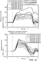
- the tuned SOCKIMO 18 is thereafter validated by using a separate data set, as shown in Figure 10 . From these volunteer tests, a corridor representing the and 0.16 th and 0.84 th quantiles of the response of 25 volunteers is used and compared to the model response.
- EXAMPLE CASE To demonstrate the methodology, an example case was selected from left turn / oncoming direction (LT/OD) conflict situations. These are characterized by the host vehicle turning left in a crossing and being struck by an oncoming vehicle that approaches from the direction opposite to the host vehicle initial direction, i.e. before the turn is initiated.
- LT/OD left turn / oncoming direction
- Case selection (elements 1-6).
- the baseline generation framework was applied.
- crashes in a TAD were classified and LT/OD crashes were identified.
- Crash case analysis was performed on the pre-crash phase of each case in detail, and a dataset was generated from all cases.
- each crash was described numerically in a THd format where each time step, during 15 seconds before the crash or near-crash, depicts the vehicle trajectories, the road environment, the participants, and their characteristics.
- variations of parameters were implemented as synthetic cases in a THd-batch, including in total 940 cases for simulation.
- Pre-crash Baseline and Treatment simulations were performed as a next step.
- all cases resulted in a collision for which the host vehicle impact speed ranged from 4 to 30 km/h, and the opponent vehicle speed ranged from 4 to 131 km/h.
- the host vehicle impact speed ranged from 4 to 30 km/h
- the opponent vehicle speed ranged from 4 to 131 km/h.
- the SOCKIMO was used to identify cases with large occupant pre-crash excursions in combination with a substantial crash severity.
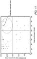
- the SOCKIMO analysis was made with an average of the seven occupant parameter sets in Figure 10 . Initially, a maximum SOCKIMO total head excursion above 150 mm during the complete pre-crash maneuver was used as filtering criterion. An additional filtering criterion was used to find one example case for which a substantial crash severity was present. Since the crash severity in the studied cases is highly governed by the impact speed of the opponent vehicle, cases with an opponent speed above 60 km/h were selected, see four encircled candidate cases in Figure 11 . A case with a crash configuration notably modified by the AEB intervention was selected, resulting in the example case described in Table 1.
- Table 1 Example case crash configurations and AEB description for Baseline and Treatment, respectively.
- Crash configuration Pre-crash intervention Host speed Opponent speed OYA HCPA OCPA Baseline 15 km/h 70 km/h 150° -45° 11° None Treatment ⁇ 0 km/h 70 km/h 151° -6° 45°
- the selected case was then simulated using the SAFER HBM occupant model positioned in the host vehicle in four different combinations of PCVK and crash pulse, as described in Table 2.
- Simulations BB and TT describe the cases from the CA-CAE tool shown in Table 1, and simulations denoted nB and TB were included in order to study the individual effects of PCVK and crash pulse, respectively.
- the FE structural crash simulations were performed using two identical mid-size passenger vehicles to provide the crash pulse needed for the FE A-HBM occupant simulation.
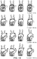
- the measured effect of the Baseline PCVK is a maximum excursion of 28 mm forward (x) and 44 mm to the right (y).
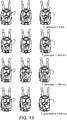
- the Treatment PCVK results in a maximum excursion 148 mm forward (x) and 46 mm to the right (y).
- the Treatment PCVK final position is 30 mm rearward (x) and 36 mm to the left (Y) of the origin.
- the Baseline crash pulse introduced a substantial lateral component to the crash pulse, which leads to occupant excursion that has approximately the same magnitude to the right as forward.
- the opponent vehicle overlaps the host vehicle to a lesser extent, thereby reducing the lateral acceleration component of the host vehicle during the crash phase.
- the Treatment crash pulse leads to an occupant excursion with low deviation from the vehicle longitudinal direction and increases the lateral excursion only during rebound.
- the present disclosure provides a CAE methodology that allows for estimation of the combined safety effects from collision avoidance and injury prevention systems.
- combinations of pre-crash maneuvers and subsequent crash was presented as an example of the feasibility of the method.
- the present methodology constitutes a framework for dealing with the large data sets that can be generated through CAE pre-crash simulations of collision avoidance technologies applied to real-world traffic situations.
- a crash configuration definition for setting up crash simulations or physical crash tests was introduced and a simplified occupant kinematic model for filtering out cases for detailed analysis is provided.
- the SOCKIMO provided an indication of large occupant pre-crash excursion that was also reflected when using the SAFER HBM.
- the SOCKIMO will point out cases where the occupant excursion is not a problem in terms of predicted injury risk during the crash phase. This depends on the combination of pre-crash maneuver and type of crash. For some crashes, certain pre-crash maneuvers may actually be beneficial for improving the occupant interaction with the restraint system, in some cases unfavorable. Another factor that influences the occupant pre-crash excursion is whether the arms are used for bracing against the steering wheel or other vehicle interior components. In the current implementation, the SOCKIMO is optionally tuned for front seat passengers for which no bracing is present, while the SAFER HBM was run as a driver with hands on the steering wheel and active arm muscles simulating this bracing.
- the crash simulation phase in this study was performed using a rigid sled, i.e. assuming no compartment intrusion. Although modern passenger vehicles often exhibit minimal intrusion, there are and will still be situations where this is not the case. Typically, this assumption could not be made when intrusion occurs in the direct surrounding of the occupant such as in side impacts. In such cases, a deformable sled where intrusions are recorded from full-scale structural FE crash simulations and then applied to the virtual sled with the A-HBM may be useful. Alternatively, the A-HBM can be placed directly in the full-scale model, however this approach is currently judged as unfeasible due to the large simulation effort that would further limit the number of studied cases.
- the proposed crash configuration method PARCC was shown to be sensitive to changes based on pre-crash AEB interventions. Although the provided example case displayed large differences in terms of PARCC parameters and subsequently significantly different resulting crash pulses, the methodology is detailed enough to describe also subtle geometrical changes in crash configuration not captured in established methods using e.g. CDC. PARCC was demonstrated in vehicle-to-vehicle crash situations, however it can also be applied to collision objects such as trucks or vulnerable road users. In order for the method to remain generic, the shape of the traffic objects should be defined in such a way that only one point is intersected at a time when a vector is swept the full 360 degrees around the object center as described in the crash configuration section.
- the present A-HBM tool is able to cover the complete sequence of events from pre-crash maneuvers to crash in one single simulation, thereby demonstrating how the tool chain efficiently contributes to evaluating the injury prevention effects from both pre-crash and crash countermeasures in the vehicle.
- FIG 15 is a network diagram of a cloud-based system 100 for implementing various cloud-based services of the present disclosure.
- the cloud-based system 100 includes one or more cloud nodes (CNs) 102 communicatively coupled to the Internet 104 or the like.
- the cloud nodes 102 may be implemented as a server 200 (as illustrated in Figure 16 ) or the like and can be geographically diverse from one another, such as located at various data centers around the country or globe.
- the cloud-based system 100 can include one or more central authority (CA) nodes 106, which similarly can be implemented as the server 200 and be connected to the CNs 102.
- CA central authority
- the cloud-based system 100 can connect to a regional office 110, headquarters 120, various employee's homes 130, laptops/desktops 140, and mobile devices 150, each of which can be communicatively coupled to one of the CNs 102. These locations 110, 120, and 130, and devices 140 and 150 are shown for illustrative purposes, and those skilled in the art will recognize there are various access scenarios to the cloud-based system 100, all of which are contemplated herein.
- the devices 140 and 150 can be so-called road warriors, i.e., users off-site, on-the-road, etc.
- the cloud-based system 100 can be a private cloud, a public cloud, a combination of a private cloud and a public cloud (hybrid cloud), or the like.
- the cloud-based system 100 can provide any functionality through services such as software-as-a-service (SaaS), platform-as-a-service, infrastructure-as-a-service, security-as-a-service, Virtual Network Functions (VNFs) in a Network Functions Virtualization (NFV) Infrastructure (NFVI), etc. to the locations 110, 120, and 130 and devices 140 and 150.
- SaaS software-as-a-service
- platform-as-a-service infrastructure-as-a-service
- security-as-a-service Virtual Network Functions (VNFs) in a Network Functions Virtualization (NFVI), etc.
- VNFs Virtual Network Functions Virtualization
- NFVI Network Functions Virtualization
- the Information Technology (IT) deployment model included enterprise resources and applications stored within an enterprise network (i.e., physical devices), behind a firewall, accessible by employees on site or remote via Virtual Private Networks (VPNs), etc.
- the cloud-based system 100 is replacing the conventional deployment model.
- Cloud computing systems and methods abstract away physical servers, storage, networking, etc., and instead offer these as on-demand and elastic resources.
- the National Institute of Standards and Technology (NIST) provides a concise and specific definition which states cloud computing is a model for enabling convenient, on-demand network access to a shared pool of configurable computing resources (e.g., networks, servers, storage, applications, and services) that can be rapidly provisioned and released with minimal management effort or service provider interaction.
- Cloud computing differs from the classic client-server model by providing applications from a server that are executed and managed by a client's web browser or the like, with no installed client version of an application required.
- the cloud-based system 100 is illustrated herein as one example embodiment of a cloud-based system, and those of ordinary skill in the art will recognize the systems and methods described herein are not necessarily limited thereby.
- FIG 16 is a block diagram of a server 200, which may be used in the cloud-based system 100 ( Figure 15 ), in other systems, or standalone.
- the CNs 102 ( Figure 15 ) and the central authority nodes 106 ( Figure 15 ) may be formed as one or more of the servers 200.
- the server 200 may be a digital computer that, in terms of hardware architecture, generally includes a processor 202, input/output (I/O) interfaces 204, a network interface 206, a data store 208, and memory 210. It should be appreciated by those of ordinary skill in the art that Figure 16 depicts the server 200 in an oversimplified manner, and a practical embodiment may include additional components and suitably configured processing logic to support known or conventional operating features that are not described in detail herein.
- the components (202, 204, 206, 208, and 210) are communicatively coupled via a local interface 212.
- the local interface 212 may be, for example, but is not limited to, one or more buses or other wired or wireless connections, as is known in the art.
- the local interface 212 may have additional elements, which are omitted for simplicity, such as controllers, buffers (caches), drivers, repeaters, and receivers, among many others, to enable communications. Further, the local interface 212 may include address, control, and/or data connections to enable appropriate communications among the aforementioned components.
- the processor 202 is a hardware device for executing software instructions.
- the processor 202 may be any custom made or commercially available processor, a central processing unit (CPU), an auxiliary processor among several processors associated with the server 200, a semiconductor-based microprocessor (in the form of a microchip or chipset), or generally any device for executing software instructions.
- the processor 202 is configured to execute software stored within the memory 210, to communicate data to and from the memory 210, and to generally control operations of the server 200 pursuant to the software instructions.
- the I/O interfaces 204 may be used to receive user input from and/or for providing system output to one or more devices or components.
- the network interface 206 may be used to enable the server 200 to communicate on a network, such as the Internet 104 ( Figure 15 ).
- the network interface 206 may include, for example, an Ethernet card or adapter (e.g., 10BaseT, Fast Ethernet, Gigabit Ethernet, or 10GbE) or a Wireless Local Area Network (WLAN) card or adapter (e.g., 802.11a/b/g/n/ac).
- the network interface 206 may include address, control, and/or data connections to enable appropriate communications on the network.
- a data store 208 may be used to store data.
- the data store 208 may include any of volatile memory elements (e.g., random access memory (RAM, such as DRAM, SRAM, SDRAM, and the like)), non-volatile memory elements (e.g., ROM, hard drive, tape, CDROM, and the like), and combinations thereof. Moreover, the data store 208 may incorporate electronic, magnetic, optical, and/or other types of storage media. In one example, the data store 208 may be located internal to the server 200, such as, for example, an internal hard drive connected to the local interface 212 in the server 200. Additionally, in another embodiment, the data store 208 may be located external to the server 200 such as, for example, an external hard drive connected to the I/O interfaces 204 (e.g., a SCSI or USB connection). In a further embodiment, the data store 208 may be connected to the server 200 through a network, such as, for example, a network-attached file server.
- RAM random access memory
- SRAM static random access memory
- SDRAM Secure Digital RAM
- the memory 210 may include any of volatile memory elements (e.g., random access memory (RAM, such as DRAM, SRAM, SDRAM, etc.)), non-volatile memory elements (e.g., ROM, hard drive, tape, CDROM, etc.), and combinations thereof. Moreover, the memory 210 may incorporate electronic, magnetic, optical, and/or other types of storage media. Note that the memory 210 may have a distributed architecture, where various components are situated remotely from one another but can be accessed by the processor 202.
- the software in memory 210 may include one or more software programs, each of which includes an ordered listing of executable instructions for implementing logical functions.
- the software in the memory 210 includes a suitable operating system (O/S) 214 and one or more programs 216.
- O/S operating system
- the operating system 214 essentially controls the execution of other computer programs, such as the one or more programs 216, and provides scheduling, input-output control, file and data management, memory management, and communication control and related services.
- the one or more programs 216 may be configured to implement the various processes, algorithms, methods, techniques, etc. described herein.
- processors such as microprocessors; central processing units (CPUs); digital signal processors (DSPs); customized processors such as network processors (NPs) or network processing units (NPUs), graphics processing units (GPUs), or the like; field programmable gate arrays (FPGAs); and the like along with unique stored program instructions (including both software and firmware) for control thereof to implement, in conjunction with certain non-processor circuits, some, most, or all of the functions of the methods and/or systems described herein.
- processors such as microprocessors; central processing units (CPUs); digital signal processors (DSPs); customized processors such as network processors (NPs) or network processing units (NPUs), graphics processing units (GPUs), or the like; field programmable gate arrays (FPGAs); and the like along with unique stored program instructions (including both software and firmware) for control thereof to implement, in conjunction with certain non-processor circuits, some, most, or all of the functions of the methods and/or systems described herein.
- processors
- circuitry configured or adapted to
- logic configured or adapted to
- some embodiments may include a non-transitory computer readable storage medium having computer readable code stored thereon for programming a computer, server, appliance, device, processor, circuit, etc. each of which may include a processor to perform functions as described and claimed herein.
- Examples of such computer readable storage mediums include, but are not limited to, a hard disk, an optical storage device, a magnetic storage device, a Read-Only Memory (ROM), a Programmable Read-Only Memory (PROM), an Erasable Programmable Read-Only Memory (EPROM), an Electrically Erasable Programmable Read-Only Memory (EEPROM), flash memory, and the like.
- software can include instructions executable by a processor or device (e.g., any type of programmable circuitry or logic) that, in response to such execution, cause a processor or the device to perform a set of operations, steps, methods, processes, algorithms, functions, techniques, etc. as described herein for the various embodiments.
- a processor or device e.g., any type of programmable circuitry or logic
- Figure 17 is a block diagram of a user device 300, which may be used in the cloud-based system 100 ( Figure 15 ) or the like.
- the user device 300 can be a smartphone, a tablet, a smartwatch, an Internet of Things (IoT) device, a laptop, a virtual reality (VR) headset, etc.
- the user device 300 can be a digital device that, in terms of hardware architecture, generally includes a processor 302, I/O interfaces 304, a radio 306, a data store 308, and memory 310. It should be appreciated by those of ordinary skill in the art that Figure 17 depicts the user device 300 in an oversimplified manner, and a practical embodiment may include additional components and suitably configured processing logic to support known or conventional operating features that are not described in detail herein.
- the components (302, 304, 306, 308, and 310) are communicatively coupled via a local interface 312.
- the local interface 312 can be, for example, but is not limited to, one or more buses or other wired or wireless connections, as is known in the art.
- the local interface 312 can have additional elements, which are omitted for simplicity, such as controllers, buffers (caches), drivers, repeaters, and receivers, among many others, to enable communications. Further, the local interface 312 may include address, control, and/or data connections to enable appropriate communications among the aforementioned components.
- the processor 302 is a hardware device for executing software instructions.
- the processor 302 can be any custom made or commercially available processor, a CPU, an auxiliary processor among several processors associated with the user device 300, a semiconductor-based microprocessor (in the form of a microchip or chipset), or generally any device for executing software instructions.
- the processor 302 is configured to execute software stored within the memory 310, to communicate data to and from the memory 310, and to generally control operations of the user device 300 pursuant to the software instructions.
- the processor 302 may include a mobile optimized processor such as optimized for power consumption and mobile applications.
- the I/O interfaces 304 can be used to receive user input from and/or for providing system output.
- System output can be provided via a display device such as a liquid crystal display (LCD), touch screen, and the like.
- LCD liquid crystal display
- the radio 306 enables wireless communication to an external access device or network. Any number of suitable wireless data communication protocols, techniques, or methodologies can be supported by the radio 306, including any protocols for wireless communication.
- the data store 308 may be used to store data.
- the data store 308 may include any of volatile memory elements (e.g., random access memory (RAM, such as DRAM, SRAM, SDRAM, and the like)), nonvolatile memory elements (e.g., ROM, hard drive, tape, CDROM, and the like), and combinations thereof.
- RAM random access memory
- nonvolatile memory elements e.g., ROM, hard drive, tape, CDROM, and the like
- the data store 308 may incorporate electronic, magnetic, optical, and/or other types of storage media.
- the memory 310 may include any of volatile memory elements (e.g., random access memory (RAM, such as DRAM, SRAM, SDRAM, etc.)), nonvolatile memory elements (e.g., ROM, hard drive, etc.), and combinations thereof. Moreover, the memory 310 may incorporate electronic, magnetic, optical, and/or other types of storage media. Note that the memory 310 may have a distributed architecture, where various components are situated remotely from one another, but can be accessed by the processor 302.
- the software in memory 310 can include one or more software programs, each of which includes an ordered listing of executable instructions for implementing logical functions. In the example of Figure 17 , the software in the memory 310 includes a suitable operating system 314 and programs 316.
- the operating system 314 essentially controls the execution of other computer programs and provides scheduling, input-output control, file and data management, memory management, and communication control and related services.
- the programs 316 may include various applications, add-ons, etc. configured to provide end user functionality with the user device 300.
- example programs 316 may include, but not limited to, a web browser, social networking applications, streaming media applications, games, mapping and location applications, electronic mail applications, financial applications, and the like.
- the end-user typically uses one or more of the programs 316 along with a network such as the cloud-based system 100 ( Figure 15 ).
Landscapes
- Engineering & Computer Science (AREA)
- Mechanical Engineering (AREA)
- Physics & Mathematics (AREA)
- Automation & Control Theory (AREA)
- Transportation (AREA)
- Geometry (AREA)
- General Physics & Mathematics (AREA)
- Theoretical Computer Science (AREA)
- Aviation & Aerospace Engineering (AREA)
- Mathematical Analysis (AREA)
- Mathematical Optimization (AREA)
- Pure & Applied Mathematics (AREA)
- Computer Hardware Design (AREA)
- Evolutionary Computation (AREA)
- General Engineering & Computer Science (AREA)
- Computational Mathematics (AREA)
- Mathematical Physics (AREA)
- Management, Administration, Business Operations System, And Electronic Commerce (AREA)
- Traffic Control Systems (AREA)
- Navigation (AREA)
Priority Applications (1)
| Application Number | Priority Date | Filing Date | Title |
|---|---|---|---|
| EP24169593.1A EP4393778A3 (de) | 2019-06-03 | 2020-06-02 | Fahrzeuggesamtsicherheitsleistungsanwendung und -verfahren mit verwendung von unfallkonfigurationsinformationen |
Applications Claiming Priority (2)
| Application Number | Priority Date | Filing Date | Title |
|---|---|---|---|
| US201962856186P | 2019-06-03 | 2019-06-03 | |
| US16/886,843 US11891053B2 (en) | 2019-06-03 | 2020-05-29 | Vehicle total safety performance application and method utilizing crash configuration information |
Related Child Applications (2)
| Application Number | Title | Priority Date | Filing Date |
|---|---|---|---|
| EP24169593.1A Division EP4393778A3 (de) | 2019-06-03 | 2020-06-02 | Fahrzeuggesamtsicherheitsleistungsanwendung und -verfahren mit verwendung von unfallkonfigurationsinformationen |
| EP24169593.1A Previously-Filed-Application EP4393778A3 (de) | 2019-06-03 | 2020-06-02 | Fahrzeuggesamtsicherheitsleistungsanwendung und -verfahren mit verwendung von unfallkonfigurationsinformationen |
Publications (2)
| Publication Number | Publication Date |
|---|---|
| EP3747706A1 true EP3747706A1 (de) | 2020-12-09 |
| EP3747706B1 EP3747706B1 (de) | 2024-04-17 |
Family
ID=71016341
Family Applications (2)
| Application Number | Title | Priority Date | Filing Date |
|---|---|---|---|
| EP24169593.1A Pending EP4393778A3 (de) | 2019-06-03 | 2020-06-02 | Fahrzeuggesamtsicherheitsleistungsanwendung und -verfahren mit verwendung von unfallkonfigurationsinformationen |
| EP20177784.4A Active EP3747706B1 (de) | 2019-06-03 | 2020-06-02 | Fahrzeuggesamtsicherheitsleistungsanwendung und -verfahren mit verwendung von unfallkonfigurationsinformationen |
Family Applications Before (1)
| Application Number | Title | Priority Date | Filing Date |
|---|---|---|---|
| EP24169593.1A Pending EP4393778A3 (de) | 2019-06-03 | 2020-06-02 | Fahrzeuggesamtsicherheitsleistungsanwendung und -verfahren mit verwendung von unfallkonfigurationsinformationen |
Country Status (3)
| Country | Link |
|---|---|
| US (1) | US11891053B2 (de) |
| EP (2) | EP4393778A3 (de) |
| CN (1) | CN112115542B (de) |
Cited By (1)
| Publication number | Priority date | Publication date | Assignee | Title |
|---|---|---|---|---|
| DE102024121308A1 (de) * | 2024-07-26 | 2026-01-29 | Audi Aktiengesellschaft | Verfahren zum Betreiben einer Fahrerassistenzanordnung, entsprechende Fahrerassistenzanordnung sowie Computerprogrammprodukt |
Families Citing this family (10)
| Publication number | Priority date | Publication date | Assignee | Title |
|---|---|---|---|---|
| CN112829742B (zh) * | 2020-12-30 | 2021-11-23 | 清华大学 | 乘员安全决策方法和装置 |
| US11553319B2 (en) | 2021-02-17 | 2023-01-10 | Qualcomm Incorporated | Evaluating vehicle-to-everything (V2X) information |
| EP4177863B1 (de) * | 2021-11-04 | 2024-04-10 | Volvo Car Corporation | Aufprallüberwachungssystem für ein fahrzeug |
| CN114371708B (zh) * | 2021-12-31 | 2023-05-02 | 清华大学 | 自动驾驶算法保护性能评测方法和装置 |
| CN115791213B (zh) | 2023-02-16 | 2023-04-18 | 中国汽车技术研究中心有限公司 | 汽车碰撞假人腰椎性能测试方法及系统、介质、设备 |
| CN116341261A (zh) * | 2023-03-30 | 2023-06-27 | 浙江吉利控股集团有限公司 | 一种场景严重度分析方法及相关装置 |
| CN116644585B (zh) * | 2023-05-30 | 2024-01-09 | 清华大学 | 基于目标车辆危险度的险态场景数据生成方法和装置 |
| DE102023129431A1 (de) | 2023-10-25 | 2025-04-30 | VAIVA GmbH | Verfahren zur Überprüfung von Fahrzeugfunktionen |
| CN119830451B (zh) * | 2024-12-23 | 2025-09-30 | 中国电子科技集团公司第二十九研究所 | 过境工作卫星载荷自主功耗优化方法、装置、介质及系统 |
| CN120597653B (zh) * | 2025-08-06 | 2025-10-10 | 中汽研(天津)汽车工程研究院有限公司 | 一种车辆的行人头部伤害评估方法及相关设备 |
Citations (7)
| Publication number | Priority date | Publication date | Assignee | Title |
|---|---|---|---|---|
| US20020103549A1 (en) * | 2001-01-31 | 2002-08-01 | John Cooper | Biomechanical system development of a restraint system |
| US20030036892A1 (en) * | 2001-08-17 | 2003-02-20 | Burge John R. | System for analyzing occupant motion during a vehicle crash |
| US20060052924A1 (en) * | 2004-09-08 | 2006-03-09 | Prakah-Asante Kwaku O | Active adaptation of vehicle restraints for enhanced performance robustness |
| EP1902908A2 (de) * | 2006-09-20 | 2008-03-26 | Audi Ag | Kollisions- und/oder Personenschutzsystem für ein Kraftfahrzeug |
| WO2009137582A1 (en) * | 2008-05-06 | 2009-11-12 | University Of Virginia Patent Foundation | System and method for minimizing occupant injury during vehicle crash events |
| EP2133244A2 (de) * | 2008-06-10 | 2009-12-16 | Audi AG | Verfahren zur prognostischen Bewertung wenigstens eines vorausschauenden Sicherheitssystems eines Kraftfahrzeugs |
| EP2233370A1 (de) * | 2009-03-26 | 2010-09-29 | Robert Bosch GmbH | Verfahren und Steuergerät zur Ermittlung von Merkmalen zum Treffen einer Auslöseentscheidung eines Insassenschutzmittels eines Fahrzeugs |
Family Cites Families (4)
| Publication number | Priority date | Publication date | Assignee | Title |
|---|---|---|---|---|
| US7243945B2 (en) | 1992-05-05 | 2007-07-17 | Automotive Technologies International, Inc. | Weight measuring systems and methods for vehicles |
| US7299677B2 (en) * | 2005-12-07 | 2007-11-27 | Chrysler Llc | Vehicle occupant analysis model for vehicle impacts |
| CN102034257A (zh) | 2010-12-31 | 2011-04-27 | 长安大学 | 汽车与两轮或三轮车碰撞事故模拟再现计算机系统 |
| US20130158809A1 (en) | 2011-12-15 | 2013-06-20 | Ford Global Technologies, Llc | Method and system for estimating real-time vehicle crash parameters |
-
2020
- 2020-05-29 US US16/886,843 patent/US11891053B2/en active Active
- 2020-06-02 EP EP24169593.1A patent/EP4393778A3/de active Pending
- 2020-06-02 EP EP20177784.4A patent/EP3747706B1/de active Active
- 2020-06-03 CN CN202010494937.4A patent/CN112115542B/zh active Active
Patent Citations (7)
| Publication number | Priority date | Publication date | Assignee | Title |
|---|---|---|---|---|
| US20020103549A1 (en) * | 2001-01-31 | 2002-08-01 | John Cooper | Biomechanical system development of a restraint system |
| US20030036892A1 (en) * | 2001-08-17 | 2003-02-20 | Burge John R. | System for analyzing occupant motion during a vehicle crash |
| US20060052924A1 (en) * | 2004-09-08 | 2006-03-09 | Prakah-Asante Kwaku O | Active adaptation of vehicle restraints for enhanced performance robustness |
| EP1902908A2 (de) * | 2006-09-20 | 2008-03-26 | Audi Ag | Kollisions- und/oder Personenschutzsystem für ein Kraftfahrzeug |
| WO2009137582A1 (en) * | 2008-05-06 | 2009-11-12 | University Of Virginia Patent Foundation | System and method for minimizing occupant injury during vehicle crash events |
| EP2133244A2 (de) * | 2008-06-10 | 2009-12-16 | Audi AG | Verfahren zur prognostischen Bewertung wenigstens eines vorausschauenden Sicherheitssystems eines Kraftfahrzeugs |
| EP2233370A1 (de) * | 2009-03-26 | 2010-09-29 | Robert Bosch GmbH | Verfahren und Steuergerät zur Ermittlung von Merkmalen zum Treffen einer Auslöseentscheidung eines Insassenschutzmittels eines Fahrzeugs |
Cited By (1)
| Publication number | Priority date | Publication date | Assignee | Title |
|---|---|---|---|---|
| DE102024121308A1 (de) * | 2024-07-26 | 2026-01-29 | Audi Aktiengesellschaft | Verfahren zum Betreiben einer Fahrerassistenzanordnung, entsprechende Fahrerassistenzanordnung sowie Computerprogrammprodukt |
Also Published As
| Publication number | Publication date |
|---|---|
| EP4393778A2 (de) | 2024-07-03 |
| CN112115542A (zh) | 2020-12-22 |
| US11891053B2 (en) | 2024-02-06 |
| EP4393778A3 (de) | 2024-08-21 |
| US20200377081A1 (en) | 2020-12-03 |
| EP3747706B1 (de) | 2024-04-17 |
| CN112115542B (zh) | 2024-04-26 |
Similar Documents
| Publication | Publication Date | Title |
|---|---|---|
| EP3747706B1 (de) | Fahrzeuggesamtsicherheitsleistungsanwendung und -verfahren mit verwendung von unfallkonfigurationsinformationen | |
| Rezvani et al. | Towards trustworthy automation: User interfaces that convey internal and external awareness | |
| US10943510B2 (en) | Customized chest response finite element model for crash test dummy and method | |
| Yanaoka et al. | Investigation on an injury criterion related to traumatic brain injury primarily induced by head rotation | |
| US20180285516A1 (en) | Customized response finite element model for crash test dummy and method | |
| Gu et al. | Multiobjective optimization design for vehicle occupant restraint system under frontal impact | |
| Perez-Rapela et al. | Methodology for vehicle safety development and assessment accounting for occupant response variability to human and non-human factors | |
| CN115099096A (zh) | 一种基于数据驱动的车辆碰撞波形预测方法、电子设备及可读存储介质 | |
| Pariota et al. | Validation of driving behaviour as a step towards the investigation of Connected and Automated Vehicles by means of driving simulators | |
| Klug et al. | Euro NCAP virtual testing-crashworthiness | |
| Linder et al. | Average male and female virtual dummy model (BioRID and EvaRID) simulations with two seat concepts in the Euro NCAP low severity rear impact test configuration | |
| Goedicke et al. | Xr-oom: Mixing virtual driving simulation with real cars and environments safely | |
| Wågström et al. | Integrated safety: Establishing links for a comprehensive virtual tool chain | |
| CN118742799A (zh) | 用于城市人机交互的测试环境 | |
| Seyedi et al. | A comprehensive assessment of bus rollover crashes: Integration of multibody dynamic and finite element simulation methods | |
| Weng et al. | Modeling small remotely piloted aircraft system to head impact for investigating craniocerebral response | |
| Ressi et al. | Protection challenges in seat positions with large rearward adjustment in frontal collisions: An approach using stochastic human body model simulations | |
| Engström et al. | Towards the automotive HMI of the future: mid-term results of the AIDE project | |
| Kouchak et al. | Non-intrusive distraction pattern detection using behavior triangulation method | |
| Shata et al. | Augmenting Driver Awareness and Performance through Haptics, Assistive Controls, and Environment Perception | |
| Zellner et al. | Extension of the Honda-DRI “Safety Impact Methodology”(SIM) for the NHTSA Advanced Crash Avoidance Technology (ACAT) Program and Application to a Prototype Advanced Collision Mitigation Braking System | |
| CN114371708A (zh) | 自动驾驶算法保护性能评测方法和装置 | |
| Zhang et al. | Digital rear view mirrors with Augmented Reality in comparison with traditional rear-view mirrors | |
| Lu et al. | Injury prediction algorithm for rear‐seat occupants in advanced automatic crash notification systems | |
| Yan et al. | Comparison of vehicle kinematics and occupant responses between Jordan rollover system and an over-the-road rollover |
Legal Events
| Date | Code | Title | Description |
|---|---|---|---|
| STAA | Information on the status of an ep patent application or granted ep patent |
Free format text: STATUS: UNKNOWN |
|
| PUAI | Public reference made under article 153(3) epc to a published international application that has entered the european phase |
Free format text: ORIGINAL CODE: 0009012 |
|
| STAA | Information on the status of an ep patent application or granted ep patent |
Free format text: STATUS: THE APPLICATION HAS BEEN PUBLISHED |
|
| AK | Designated contracting states |
Kind code of ref document: A1 Designated state(s): AL AT BE BG CH CY CZ DE DK EE ES FI FR GB GR HR HU IE IS IT LI LT LU LV MC MK MT NL NO PL PT RO RS SE SI SK SM TR |
|
| AX | Request for extension of the european patent |
Extension state: BA ME |
|
| STAA | Information on the status of an ep patent application or granted ep patent |
Free format text: STATUS: REQUEST FOR EXAMINATION WAS MADE |
|
| 17P | Request for examination filed |
Effective date: 20210609 |
|
| RBV | Designated contracting states (corrected) |
Designated state(s): AL AT BE BG CH CY CZ DE DK EE ES FI FR GB GR HR HU IE IS IT LI LT LU LV MC MK MT NL NO PL PT RO RS SE SI SK SM TR |
|
| STAA | Information on the status of an ep patent application or granted ep patent |
Free format text: STATUS: EXAMINATION IS IN PROGRESS |
|
| 17Q | First examination report despatched |
Effective date: 20230706 |
|
| P01 | Opt-out of the competence of the unified patent court (upc) registered |
Effective date: 20230828 |
|
| GRAP | Despatch of communication of intention to grant a patent |
Free format text: ORIGINAL CODE: EPIDOSNIGR1 |
|
| STAA | Information on the status of an ep patent application or granted ep patent |
Free format text: STATUS: GRANT OF PATENT IS INTENDED |
|
| INTG | Intention to grant announced |
Effective date: 20231206 |
|
| GRAS | Grant fee paid |
Free format text: ORIGINAL CODE: EPIDOSNIGR3 |
|
| GRAA | (expected) grant |
Free format text: ORIGINAL CODE: 0009210 |
|
| STAA | Information on the status of an ep patent application or granted ep patent |
Free format text: STATUS: THE PATENT HAS BEEN GRANTED |
|
| AK | Designated contracting states |
Kind code of ref document: B1 Designated state(s): AL AT BE BG CH CY CZ DE DK EE ES FI FR GB GR HR HU IE IS IT LI LT LU LV MC MK MT NL NO PL PT RO RS SE SI SK SM TR |
|
| REG | Reference to a national code |
Ref country code: GB Ref legal event code: FG4D |
|
| REG | Reference to a national code |
Ref country code: CH Ref legal event code: EP |
|
| REG | Reference to a national code |
Ref country code: IE Ref legal event code: FG4D Ref country code: DE Ref legal event code: R096 Ref document number: 602020029019 Country of ref document: DE |
|
| REG | Reference to a national code |
Ref country code: LT Ref legal event code: MG9D |
|
| REG | Reference to a national code |
Ref country code: NL Ref legal event code: MP Effective date: 20240417 |
|
| REG | Reference to a national code |
Ref country code: AT Ref legal event code: MK05 Ref document number: 1676970 Country of ref document: AT Kind code of ref document: T Effective date: 20240417 |
|
| PG25 | Lapsed in a contracting state [announced via postgrant information from national office to epo] |
Ref country code: NL Free format text: LAPSE BECAUSE OF FAILURE TO SUBMIT A TRANSLATION OF THE DESCRIPTION OR TO PAY THE FEE WITHIN THE PRESCRIBED TIME-LIMIT Effective date: 20240417 |
|
| PG25 | Lapsed in a contracting state [announced via postgrant information from national office to epo] |
Ref country code: NL Free format text: LAPSE BECAUSE OF FAILURE TO SUBMIT A TRANSLATION OF THE DESCRIPTION OR TO PAY THE FEE WITHIN THE PRESCRIBED TIME-LIMIT Effective date: 20240417 |
|
| PG25 | Lapsed in a contracting state [announced via postgrant information from national office to epo] |
Ref country code: IS Free format text: LAPSE BECAUSE OF FAILURE TO SUBMIT A TRANSLATION OF THE DESCRIPTION OR TO PAY THE FEE WITHIN THE PRESCRIBED TIME-LIMIT Effective date: 20240817 |
|
| PG25 | Lapsed in a contracting state [announced via postgrant information from national office to epo] |
Ref country code: BG Free format text: LAPSE BECAUSE OF FAILURE TO SUBMIT A TRANSLATION OF THE DESCRIPTION OR TO PAY THE FEE WITHIN THE PRESCRIBED TIME-LIMIT Effective date: 20240417 |
|
| PG25 | Lapsed in a contracting state [announced via postgrant information from national office to epo] |
Ref country code: HR Free format text: LAPSE BECAUSE OF FAILURE TO SUBMIT A TRANSLATION OF THE DESCRIPTION OR TO PAY THE FEE WITHIN THE PRESCRIBED TIME-LIMIT Effective date: 20240417 Ref country code: FI Free format text: LAPSE BECAUSE OF FAILURE TO SUBMIT A TRANSLATION OF THE DESCRIPTION OR TO PAY THE FEE WITHIN THE PRESCRIBED TIME-LIMIT Effective date: 20240417 |
|
| PG25 | Lapsed in a contracting state [announced via postgrant information from national office to epo] |
Ref country code: GR Free format text: LAPSE BECAUSE OF FAILURE TO SUBMIT A TRANSLATION OF THE DESCRIPTION OR TO PAY THE FEE WITHIN THE PRESCRIBED TIME-LIMIT Effective date: 20240718 |
|
| PG25 | Lapsed in a contracting state [announced via postgrant information from national office to epo] |
Ref country code: PT Free format text: LAPSE BECAUSE OF FAILURE TO SUBMIT A TRANSLATION OF THE DESCRIPTION OR TO PAY THE FEE WITHIN THE PRESCRIBED TIME-LIMIT Effective date: 20240819 |
|
| PG25 | Lapsed in a contracting state [announced via postgrant information from national office to epo] |
Ref country code: ES Free format text: LAPSE BECAUSE OF FAILURE TO SUBMIT A TRANSLATION OF THE DESCRIPTION OR TO PAY THE FEE WITHIN THE PRESCRIBED TIME-LIMIT Effective date: 20240417 |
|
| PG25 | Lapsed in a contracting state [announced via postgrant information from national office to epo] |
Ref country code: AT Free format text: LAPSE BECAUSE OF FAILURE TO SUBMIT A TRANSLATION OF THE DESCRIPTION OR TO PAY THE FEE WITHIN THE PRESCRIBED TIME-LIMIT Effective date: 20240417 |
|
| PG25 | Lapsed in a contracting state [announced via postgrant information from national office to epo] |
Ref country code: PL Free format text: LAPSE BECAUSE OF FAILURE TO SUBMIT A TRANSLATION OF THE DESCRIPTION OR TO PAY THE FEE WITHIN THE PRESCRIBED TIME-LIMIT Effective date: 20240417 |
|
| PG25 | Lapsed in a contracting state [announced via postgrant information from national office to epo] |
Ref country code: LV Free format text: LAPSE BECAUSE OF FAILURE TO SUBMIT A TRANSLATION OF THE DESCRIPTION OR TO PAY THE FEE WITHIN THE PRESCRIBED TIME-LIMIT Effective date: 20240417 |
|
| PG25 | Lapsed in a contracting state [announced via postgrant information from national office to epo] |
Ref country code: PT Free format text: LAPSE BECAUSE OF FAILURE TO SUBMIT A TRANSLATION OF THE DESCRIPTION OR TO PAY THE FEE WITHIN THE PRESCRIBED TIME-LIMIT Effective date: 20240819 Ref country code: PL Free format text: LAPSE BECAUSE OF FAILURE TO SUBMIT A TRANSLATION OF THE DESCRIPTION OR TO PAY THE FEE WITHIN THE PRESCRIBED TIME-LIMIT Effective date: 20240417 Ref country code: NO Free format text: LAPSE BECAUSE OF FAILURE TO SUBMIT A TRANSLATION OF THE DESCRIPTION OR TO PAY THE FEE WITHIN THE PRESCRIBED TIME-LIMIT Effective date: 20240717 Ref country code: LV Free format text: LAPSE BECAUSE OF FAILURE TO SUBMIT A TRANSLATION OF THE DESCRIPTION OR TO PAY THE FEE WITHIN THE PRESCRIBED TIME-LIMIT Effective date: 20240417 Ref country code: IS Free format text: LAPSE BECAUSE OF FAILURE TO SUBMIT A TRANSLATION OF THE DESCRIPTION OR TO PAY THE FEE WITHIN THE PRESCRIBED TIME-LIMIT Effective date: 20240817 Ref country code: HR Free format text: LAPSE BECAUSE OF FAILURE TO SUBMIT A TRANSLATION OF THE DESCRIPTION OR TO PAY THE FEE WITHIN THE PRESCRIBED TIME-LIMIT Effective date: 20240417 Ref country code: GR Free format text: LAPSE BECAUSE OF FAILURE TO SUBMIT A TRANSLATION OF THE DESCRIPTION OR TO PAY THE FEE WITHIN THE PRESCRIBED TIME-LIMIT Effective date: 20240718 Ref country code: FI Free format text: LAPSE BECAUSE OF FAILURE TO SUBMIT A TRANSLATION OF THE DESCRIPTION OR TO PAY THE FEE WITHIN THE PRESCRIBED TIME-LIMIT Effective date: 20240417 Ref country code: ES Free format text: LAPSE BECAUSE OF FAILURE TO SUBMIT A TRANSLATION OF THE DESCRIPTION OR TO PAY THE FEE WITHIN THE PRESCRIBED TIME-LIMIT Effective date: 20240417 Ref country code: BG Free format text: LAPSE BECAUSE OF FAILURE TO SUBMIT A TRANSLATION OF THE DESCRIPTION OR TO PAY THE FEE WITHIN THE PRESCRIBED TIME-LIMIT Effective date: 20240417 Ref country code: AT Free format text: LAPSE BECAUSE OF FAILURE TO SUBMIT A TRANSLATION OF THE DESCRIPTION OR TO PAY THE FEE WITHIN THE PRESCRIBED TIME-LIMIT Effective date: 20240417 Ref country code: RS Free format text: LAPSE BECAUSE OF FAILURE TO SUBMIT A TRANSLATION OF THE DESCRIPTION OR TO PAY THE FEE WITHIN THE PRESCRIBED TIME-LIMIT Effective date: 20240717 |
|
| PG25 | Lapsed in a contracting state [announced via postgrant information from national office to epo] |
Ref country code: DK Free format text: LAPSE BECAUSE OF FAILURE TO SUBMIT A TRANSLATION OF THE DESCRIPTION OR TO PAY THE FEE WITHIN THE PRESCRIBED TIME-LIMIT Effective date: 20240417 |
|
| REG | Reference to a national code |
Ref country code: DE Ref legal event code: R097 Ref document number: 602020029019 Country of ref document: DE |
|
| PG25 | Lapsed in a contracting state [announced via postgrant information from national office to epo] |
Ref country code: EE Free format text: LAPSE BECAUSE OF FAILURE TO SUBMIT A TRANSLATION OF THE DESCRIPTION OR TO PAY THE FEE WITHIN THE PRESCRIBED TIME-LIMIT Effective date: 20240417 |
|
| PG25 | Lapsed in a contracting state [announced via postgrant information from national office to epo] |
Ref country code: CZ Free format text: LAPSE BECAUSE OF FAILURE TO SUBMIT A TRANSLATION OF THE DESCRIPTION OR TO PAY THE FEE WITHIN THE PRESCRIBED TIME-LIMIT Effective date: 20240417 |
|
| PG25 | Lapsed in a contracting state [announced via postgrant information from national office to epo] |
Ref country code: SK Free format text: LAPSE BECAUSE OF FAILURE TO SUBMIT A TRANSLATION OF THE DESCRIPTION OR TO PAY THE FEE WITHIN THE PRESCRIBED TIME-LIMIT Effective date: 20240417 Ref country code: RO Free format text: LAPSE BECAUSE OF FAILURE TO SUBMIT A TRANSLATION OF THE DESCRIPTION OR TO PAY THE FEE WITHIN THE PRESCRIBED TIME-LIMIT Effective date: 20240417 |
|
| PG25 | Lapsed in a contracting state [announced via postgrant information from national office to epo] |
Ref country code: SM Free format text: LAPSE BECAUSE OF FAILURE TO SUBMIT A TRANSLATION OF THE DESCRIPTION OR TO PAY THE FEE WITHIN THE PRESCRIBED TIME-LIMIT Effective date: 20240417 |
|
| PG25 | Lapsed in a contracting state [announced via postgrant information from national office to epo] |
Ref country code: SM Free format text: LAPSE BECAUSE OF FAILURE TO SUBMIT A TRANSLATION OF THE DESCRIPTION OR TO PAY THE FEE WITHIN THE PRESCRIBED TIME-LIMIT Effective date: 20240417 Ref country code: SK Free format text: LAPSE BECAUSE OF FAILURE TO SUBMIT A TRANSLATION OF THE DESCRIPTION OR TO PAY THE FEE WITHIN THE PRESCRIBED TIME-LIMIT Effective date: 20240417 Ref country code: RO Free format text: LAPSE BECAUSE OF FAILURE TO SUBMIT A TRANSLATION OF THE DESCRIPTION OR TO PAY THE FEE WITHIN THE PRESCRIBED TIME-LIMIT Effective date: 20240417 Ref country code: EE Free format text: LAPSE BECAUSE OF FAILURE TO SUBMIT A TRANSLATION OF THE DESCRIPTION OR TO PAY THE FEE WITHIN THE PRESCRIBED TIME-LIMIT Effective date: 20240417 Ref country code: DK Free format text: LAPSE BECAUSE OF FAILURE TO SUBMIT A TRANSLATION OF THE DESCRIPTION OR TO PAY THE FEE WITHIN THE PRESCRIBED TIME-LIMIT Effective date: 20240417 Ref country code: CZ Free format text: LAPSE BECAUSE OF FAILURE TO SUBMIT A TRANSLATION OF THE DESCRIPTION OR TO PAY THE FEE WITHIN THE PRESCRIBED TIME-LIMIT Effective date: 20240417 Ref country code: MC Free format text: LAPSE BECAUSE OF FAILURE TO SUBMIT A TRANSLATION OF THE DESCRIPTION OR TO PAY THE FEE WITHIN THE PRESCRIBED TIME-LIMIT Effective date: 20240417 |
|
| REG | Reference to a national code |
Ref country code: CH Ref legal event code: PL |
|
| PG25 | Lapsed in a contracting state [announced via postgrant information from national office to epo] |
Ref country code: IT Free format text: LAPSE BECAUSE OF FAILURE TO SUBMIT A TRANSLATION OF THE DESCRIPTION OR TO PAY THE FEE WITHIN THE PRESCRIBED TIME-LIMIT Effective date: 20240417 |
|
| PG25 | Lapsed in a contracting state [announced via postgrant information from national office to epo] |
Ref country code: LU Free format text: LAPSE BECAUSE OF NON-PAYMENT OF DUE FEES Effective date: 20240602 |
|
| PLBE | No opposition filed within time limit |
Free format text: ORIGINAL CODE: 0009261 |
|
| STAA | Information on the status of an ep patent application or granted ep patent |
Free format text: STATUS: NO OPPOSITION FILED WITHIN TIME LIMIT |
|
| 26N | No opposition filed |
Effective date: 20250120 |
|
| PG25 | Lapsed in a contracting state [announced via postgrant information from national office to epo] |
Ref country code: IE Free format text: LAPSE BECAUSE OF NON-PAYMENT OF DUE FEES Effective date: 20240602 |
|
| PG25 | Lapsed in a contracting state [announced via postgrant information from national office to epo] |
Ref country code: SI Free format text: LAPSE BECAUSE OF FAILURE TO SUBMIT A TRANSLATION OF THE DESCRIPTION OR TO PAY THE FEE WITHIN THE PRESCRIBED TIME-LIMIT Effective date: 20240417 Ref country code: BE Free format text: LAPSE BECAUSE OF NON-PAYMENT OF DUE FEES Effective date: 20240630 Ref country code: CH Free format text: LAPSE BECAUSE OF NON-PAYMENT OF DUE FEES Effective date: 20240630 |
|
| REG | Reference to a national code |
Ref country code: BE Ref legal event code: MM Effective date: 20240630 |
|
| PGFP | Annual fee paid to national office [announced via postgrant information from national office to epo] |
Ref country code: DE Payment date: 20250520 Year of fee payment: 6 |
|
| PGFP | Annual fee paid to national office [announced via postgrant information from national office to epo] |
Ref country code: GB Payment date: 20250520 Year of fee payment: 6 |
|
| PGFP | Annual fee paid to national office [announced via postgrant information from national office to epo] |
Ref country code: FR Payment date: 20250520 Year of fee payment: 6 |
|
| PG25 | Lapsed in a contracting state [announced via postgrant information from national office to epo] |
Ref country code: SE Free format text: LAPSE BECAUSE OF FAILURE TO SUBMIT A TRANSLATION OF THE DESCRIPTION OR TO PAY THE FEE WITHIN THE PRESCRIBED TIME-LIMIT Effective date: 20240417 |
|
| PG25 | Lapsed in a contracting state [announced via postgrant information from national office to epo] |
Ref country code: CY Free format text: LAPSE BECAUSE OF FAILURE TO SUBMIT A TRANSLATION OF THE DESCRIPTION OR TO PAY THE FEE WITHIN THE PRESCRIBED TIME-LIMIT; INVALID AB INITIO Effective date: 20200602 |
|
| PG25 | Lapsed in a contracting state [announced via postgrant information from national office to epo] |
Ref country code: HU Free format text: LAPSE BECAUSE OF FAILURE TO SUBMIT A TRANSLATION OF THE DESCRIPTION OR TO PAY THE FEE WITHIN THE PRESCRIBED TIME-LIMIT; INVALID AB INITIO Effective date: 20200602 |