EP3748062B1 - Dispositif de traitement de vêtements - Google Patents
Dispositif de traitement de vêtements Download PDFInfo
- Publication number
- EP3748062B1 EP3748062B1 EP19747563.5A EP19747563A EP3748062B1 EP 3748062 B1 EP3748062 B1 EP 3748062B1 EP 19747563 A EP19747563 A EP 19747563A EP 3748062 B1 EP3748062 B1 EP 3748062B1
- Authority
- EP
- European Patent Office
- Prior art keywords
- air duct
- air
- baffle
- clothing treating
- conversion device
- Prior art date
- Legal status (The legal status is an assumption and is not a legal conclusion. Google has not performed a legal analysis and makes no representation as to the accuracy of the status listed.)
- Active
Links
Images







Classifications
-
- D—TEXTILES; PAPER
- D06—TREATMENT OF TEXTILES OR THE LIKE; LAUNDERING; FLEXIBLE MATERIALS NOT OTHERWISE PROVIDED FOR
- D06F—LAUNDERING, DRYING, IRONING, PRESSING OR FOLDING TEXTILE ARTICLES
- D06F58/00—Domestic laundry dryers
- D06F58/10—Drying cabinets or drying chambers having heating or ventilating means
-
- D—TEXTILES; PAPER
- D06—TREATMENT OF TEXTILES OR THE LIKE; LAUNDERING; FLEXIBLE MATERIALS NOT OTHERWISE PROVIDED FOR
- D06F—LAUNDERING, DRYING, IRONING, PRESSING OR FOLDING TEXTILE ARTICLES
- D06F29/00—Combinations of a washing machine with other separate apparatus in a common frame or the like, e.g. with rinsing apparatus
-
- D—TEXTILES; PAPER
- D06—TREATMENT OF TEXTILES OR THE LIKE; LAUNDERING; FLEXIBLE MATERIALS NOT OTHERWISE PROVIDED FOR
- D06F—LAUNDERING, DRYING, IRONING, PRESSING OR FOLDING TEXTILE ARTICLES
- D06F58/00—Domestic laundry dryers
- D06F58/02—Domestic laundry dryers having dryer drums rotating about a horizontal axis
- D06F58/04—Details
-
- D—TEXTILES; PAPER
- D06—TREATMENT OF TEXTILES OR THE LIKE; LAUNDERING; FLEXIBLE MATERIALS NOT OTHERWISE PROVIDED FOR
- D06F—LAUNDERING, DRYING, IRONING, PRESSING OR FOLDING TEXTILE ARTICLES
- D06F58/00—Domestic laundry dryers
- D06F58/32—Control of operations performed in domestic laundry dryers
- D06F58/34—Control of operations performed in domestic laundry dryers characterised by the purpose or target of the control
- D06F58/36—Control of operational steps, e.g. for optimisation or improvement of operational steps depending on the condition of the laundry
-
- D—TEXTILES; PAPER
- D06—TREATMENT OF TEXTILES OR THE LIKE; LAUNDERING; FLEXIBLE MATERIALS NOT OTHERWISE PROVIDED FOR
- D06F—LAUNDERING, DRYING, IRONING, PRESSING OR FOLDING TEXTILE ARTICLES
- D06F29/00—Combinations of a washing machine with other separate apparatus in a common frame or the like, e.g. with rinsing apparatus
- D06F29/005—Combinations of a washing machine with other separate apparatus in a common frame or the like, e.g. with rinsing apparatus the other separate apparatus being a drying appliance
-
- D—TEXTILES; PAPER
- D06—TREATMENT OF TEXTILES OR THE LIKE; LAUNDERING; FLEXIBLE MATERIALS NOT OTHERWISE PROVIDED FOR
- D06F—LAUNDERING, DRYING, IRONING, PRESSING OR FOLDING TEXTILE ARTICLES
- D06F58/00—Domestic laundry dryers
- D06F58/02—Domestic laundry dryers having dryer drums rotating about a horizontal axis
-
- D—TEXTILES; PAPER
- D06—TREATMENT OF TEXTILES OR THE LIKE; LAUNDERING; FLEXIBLE MATERIALS NOT OTHERWISE PROVIDED FOR
- D06F—LAUNDERING, DRYING, IRONING, PRESSING OR FOLDING TEXTILE ARTICLES
- D06F58/00—Domestic laundry dryers
- D06F58/20—General details of domestic laundry dryers
-
- D—TEXTILES; PAPER
- D06—TREATMENT OF TEXTILES OR THE LIKE; LAUNDERING; FLEXIBLE MATERIALS NOT OTHERWISE PROVIDED FOR
- D06F—LAUNDERING, DRYING, IRONING, PRESSING OR FOLDING TEXTILE ARTICLES
- D06F58/00—Domestic laundry dryers
- D06F58/30—Drying processes
Definitions
- the present invention relates a clothing treating device.
- the drying and washing all-in-one machine in the prior art generally adopts a condensing clothes drying manner in a drying mode, that is to say, a closed air duct is adopted.
- Heating drying air heated by a condenser is sent to a drum filled with clothes, moist air which seizes moisture from clothes is sent back to an evaporator for dehumidification, the dehumidified air is heated again by the condenser, and is sent to the drum, the process is repeated and moisture on the clothes is constantly brought away until the clothes are dry.
- US 2007/119072 A1 discloses a cabinet which includes a hot air guide duct for guiding the hot air produced by a heater to the drying drum and the washing and drying combination drum.
- the drying and washing all-in-one machine in the prior art generally adopts a water-cooled type or a compressor type in a cooling mode, tap water or a compressor is utilized to drive, to lower the temperature in the drum.
- tap water-type cooling method is low in cooling efficiency, the cooling time is long, and water resource is simultaneously wasted; and as to the condenser-type cooling mode, although the efficiency is high and the time is short, the cost is extremely high.
- the applicant designed a clothing treating device possessing two sets of clothing treating equipment before.
- the two sets of clothing treating equipment can respectively dry clothes; however, in the prior art, the drying equipment can only dry clothes in a single clothing treating equipment; therefore, when two sets of drying equipment are added on the clothing treating device, the size of the whole device structure is enlarged, the number of equipment is increased, thereby leading to increased product cost and increased occupied space.
- the technical problem to be solved in the present disclosure is to overcome shortcomings of the prior art, and provide a clothing treating device having two sets of clothing treating equipment, which is able to dry clothes in the two clothing treating equipment at the same time.
- the present disclosure has the following beneficial effects compared with the prior art.
- a single air duct can provide a circulating air flow for drying clothes to the first clothing treating bucket or the second clothing treating bucket, respectively, thereby further achieving the purpose of sharing one drying air duct by two sets of clothing drying equipment, and achieving the purpose of sharing the same clothing drying air duct on the clothing treating device possessing two sets of clothing treating equipment.
- the air duct baffle in the air duct correspondingly swings and rotates along with the rotation of the output shaft of the motor, thereby controlling the corresponding closing or opening of different openings in the air duct, and achieving the purpose of controlling the reversal of direction of the air flow in the air duct.
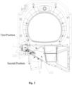
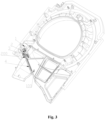
- an embodiment of the present disclosure introduces an air duct conversion device 200 which includes an air duct baffle 4 which is installed on the air duct 100 in a manner of being capable of rotating relatively; an output shaft of a motor 1 is connected with the air duct baffle 4 through a linkage mechanism, to drive the air duct baffle 4 to rotate around the shaft through the linkage mechanism in the rotating process of the output shaft of the motor 1, such that the air duct baffle 4 switches to move between a first position and a second position.
- the air duct baffle in the air duct correspondingly swings and rotates along with the rotation of the output shaft of the motor, thereby controlling the corresponding closing or opening of different openings in the air duct, and achieving the purpose of controlling the reversal of direction of the air flow in the air duct.
- the linkage mechanism includes an adaptor 3 and a connecting beam 2 which are connected in a manner of capable of rotating relatively, the connecting beam 2 is in inserting connection with the output shaft of the motor 1 in a manner of capable of rotating around the output shaft of the motor 1, and the adaptor 3 is in inserting connection with the baffle shaft 411 of the air duct baffle 4 in a manner of incapable of rotating relatively.
- the output shaft of the motor 1 is at a position far away from the air duct 100
- the connecting beam 2 is driven to a position far away from the air duct 100
- the adaptor 3 moves to the uppermost end, such that the air duct baffle 4 rotates upwards along the shaft to the first position, to close an opening at the upper end of the air duct 100, and the air duct 100 is communicated with the opening at the lower end.
- one end of the air duct baffle 4 is provided with a baffle shaft 411 which extends horizontally towards two sides, the baffle shaft 411 and the two side walls of the air duct 100 are correspondingly in inserting connection and fixation, such that the baffle 4 can be installed in the air duct 100 in a manner of capable of rotating relatively; and one end of the baffle shaft 411 penetrates through the air duct 100 and is fixedly connected with the adaptor 3.
- two ends of the connecting beam 2 are respectively fixedly installed with a first joint 21 and a second joint 22, the first joint 21 is in inserting connection with the coupling shaft 31 of the adaptor 3 in a manner of capable of relatively rotating around the shaft, and the second joint 22 is in inserting connection with the eccentric shaft section 111 of the motor 1 in a manner of capable of relatively rotating around the shaft.
- the output shaft of the motor is of an eccentric shaft structure
- the eccentric shaft structure includes an eccentric shaft section 111 which rotates around the motor center
- the eccentric shaft section 111 and the second joint 22 of the connecting beam 2 are in inserting connection in a manner of capable of relatively rotating around a shaft, to drive the connecting beam 3 to move in the rotating process of the eccentric shaft section 111, and further to drive the air duct baffle 4 to rotate around the baffle shaft 411 through an adaptor 3, and further to control the eccentric shaft section of the output shaft of the motor to swing and rotate mutually between the uppermost end and the lowermost end, and to correspondingly control the mutual switching of the air duct baffle between the first position and the second position.
- the present embodiment introduces a shaft sleeve structure for the installation of a baffle shaft of the air duct conversion device
- one end of the air duct baffle 4 is provided with a baffle shaft 411 which extends horizontally towards the two sides, the baffle shaft 411 and two side walls of the air duct 100 are correspondingly in inserting connection and fixation, such that the baffle 411 is installed in the air duct 100 in a manner of capable of rotating relatively; one end of the baffle shaft 411 after penetrates through the air duct 100 and is fixedly connected with the adaptor 3.
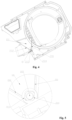
- the side wall 101 of the air duct is provided with an installation groove 203, the installation groove 203 is connected in an inserting manner and fixed with a bearing sleeve 204 with a non-circular periphery, and the bearing sleeve 204 is provided with an installation hole 205 which allows the baffle shaft 411 of the air duct baffle 4 to be correspondingly connected in an inserting manner.
- the bearing of the air duct reversing device can be replaced detachably, thereby achieving the purpose of detachable installation and rapid assembly and replacement of a bearing sleeve of a baffle shaft.
- the extension direction of the installation groove 203 is vertical to the side wall of the air duct
- the hollow part in the installation groove 203 allows corresponding inserting connection and fixation of the bearing sleeve 204
- the axial direction of the installation hole 205 of the bearing sleeve 204 is set to be vertical to the side wall 101 of the air duct.
- the cross section of the inner wall of the installation groove 203 is square
- the peripheral cross section of the bearing sleeve 204 is a square which is in corresponding matching and fitting with the installation groove 203.
- the peripheral cross section of the bearing sleeve 204 is a square which is provided with a chamfer at each of the corners, and the corner is any shape selected from a circular arc and a straight line.
- the peripheral cross section of the bearing shaft 204 is a regular hexagon
- the cross section of the inner wall of the installation groove 203 is a square
- the distance between two opposite sides of the regular hexagon is equal to the length of the side of the square.
- the side wall 101 of the air duct is provided with a first retaining rib 201 and a second retaining rib 202 which are crossed and arranged at a certain angle, and the installation groove 203 is arranged at the position at which the first retaining rib 201 and the second retaining rib 202 are intersected.
- the axis of the bearing sleeve 204 installed in the installation groove 203 is coincided with the intersection point of the extension directions of the first retaining rib 201 and the second retaining rib 202.
- the first retaining rib 201 and the second retaining rib 202 protrude to extend towards the inside of the air duct 100 from the side wall 101 of the air duct, and the first retaining wall 201 extends along the first position of the air duct baffle 4 of the air duct conversion device 200, and the second retaining rib 202 extends along the second position of the air duct baffle 4 of the air duct conversion device 200, such that the air duct baffle 4 rotates around the baffle shaft 41 between the first retaining rib 201 and the second retaining rib 202.
- the cross section of the installation hole 205 on the bearing sleeve 204 is a circular hole which is in corresponding inserting connection with the baffle shaft 411, and the diameter of the circular hole is set to be equal to the diameter of the baffle shaft 411.
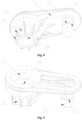
- the present embodiment introduces an adaptor 3 for the air duct conversion device, two ends of the adaptor 3 are respectively provided with a coupling shaft 31 and a coupling sleeve 32.
- the coupling shaft 31 is connected with the connecting beam 2 of the air duct conversion device 200 in a manner of capable of rotating around the shaft, and the coupling sleeve 32 is fixedly connected with the air duct baffle 4 of the air duct conversion device 200 in a manner of incapable of relatively rotating.
- the adaptor is integrated with two different inserting connection structures, thereby ensuring that two ends of an adaptor are respectively correspondingly connected with different components in a manner of capable or rotating and in a manner of incapable of rotating relatively and achieving the purpose of driving the air duct baffle of the air duct conversion device.
- the axis of the coupling sleeve 32 and the axis of the coupling shaft 31 are arranged to be in parallel, and the coupling sleeve 32 and the coupling shaft 31 are arranged at the same side of the adaptor 3.
- the axis of the coupling shaft 31 and the axis of the coupling sleeve 32 are arranged to be in parallel, and the coupling shaft 31 and the coupling sleeve 32 are both arranged to be vertical to the extension direction of the adaptor 3.
- the coupling sleeve 32 is a sleeve structure which extends in a protruding manner towards one side from the adaptor, the opening at one end of the sleeve structure allows corresponding insertion of the baffle shaft 411 of the air duct conversion device 100, and the other end is provided with a jack socket 36 for the baffle shaft to penetrate out.
- the adaptor 3 is provided with a countersink groove 35 for the installation of the lock nut 33, the countersink groove 35 is set to be co-axial with the coupling sleeve 32, and is arranged at two opposite sides of the adaptor 3, the countersink groove 35 is communicated with the coupling sleeve 32 through a jack socket 36, and the countersink groove 35, the jack socket 36 and the coupling sleeve 32 are all arranged coaxially.
- the opening part of the countersink groove 35 is provided with a ring of protruding ribs which protrude outwards and which are arranged exceeding the side face corresponding to the adaptor, such that a user can tighten the lock nut in the countersink groove.
- the lock nut is embedded in the countersink groove, thereby ensuring that an outer end face of the lock nut does not protrude out of the adaptor, and further improving overall compactness of the air duct conversion device.
- the periphery of the coupling sleeve 32 is provided with multiple reinforcing ribs 34 which are distributed at intervals and which extend towards a parallel direction along the axis of the sleeve structure, the lower end of the reinforcing rib 34 extends to the adaptor 3 and the upper end extends to the end part of the sleeve structure.
- the circumferential cross section of the coupling sleeve 32 of the sleeve structure is non-circular, such that after the baffle shaft 411 is correspondingly connected in an inserting manner, an inserting connection and fixation incapable of relatively rotating is formed.
- the circumferential cross section of the coupling sleeve 32 of the sleeve structure is part of a circle intercepted by two parallel segments, that is, the circumferential cross section of the coupling sleeve 32 is an irregular shape which is encircled by two parallel segments at two opposite sides and two symmetrical arc segments at another two opposite sides.
- the coupling shaft 31 is a columnar structure which extends in a protruding manner towards one side from the adaptor, the axis of the columnar-structure coupling shaft 31 is vertical to the extension direction of the adaptor 3, the height of the columnar-structure coupling shaft 31 is set to be as the same with the height of the coupling sleeve 32, and the cross section of the columnar-structure coupling shaft 31 is circular.
- the middle of the columnar-structure coupling shaft 31 is provided with a ring of grooves 37 which extend along the outer wall of the adaptor, to allow corresponding inserting connection of the bulge on the joint of the connecting beam 2; and the extending surface of the groove 37 is vertical to the axis of the coupling shaft 31.
- the connecting beam can drive the adaptor to rotate in a large angle only when the connecting beam swings at a small angle, thereby ensuring the rotating range of the air duct baffle, and reducing the movement path of the air duct conversion device.
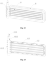
- the present embodiment introduces an air duct baffle 4 of an air duct conversion device 200, wherein the air duct baffle 4 includes a baffle body 41 and a frame 42, one side of the baffle body 41 is provided with a baffle shaft 411 which extends horizontally towards two sides, and the frame wraps the three sides, except the baffle shaft 411, of the baffle body.
- the baffle body 41 and the baffle shaft 411 are set to be integrated, and can rotate together under the driving of the motor 1, to open or close the air duct 100.
- the air duct conversion device 200 is fixed on a housing through a fixed device, and the air duct baffle 4 switches to move between the first position and the second position, to open or close the air duct 100.
- the gas can only flow along a specified path, thereby avoiding gas leakage.
- the baffle shaft 411 of the air duct baffle 4 is connected with the fixed device, the adaptor 3 of the air duct conversion device 200 and the side wall of the air duct, respectively, to install and fix the air duct baffle 4.
- the adaptor 3 drives the baffle shaft 411 to rotate, and further drives the whole air duct baffle 4 to rotate.
- the end part of the baffle shaft 411 penetrating out of the air duct baffle 4 is stair-stepping
- the baffle shaft 411 is provided with a first shaft section 4111 and a second shaft section 4112 in sequence from outside to inside.
- the diameter of the second shaft section 4112 is larger than the diameter of the first shaft section 4111
- the top end of the first shaft section 4111 is connected with a side wall of the air duct
- the second shaft section 4112 is connected with the other end of the first shaft section 4111 and extends along an axial direction of the first shaft section 4111.
- the cross section of the second shaft section 4112 is non-circular, the outer wall of the second shaft section 4112 is correspondingly fit with and in inserting connection with the inner circumferential surface of the coupling sleeve 32 of the adaptor 3, such that the second shaft section 4112 is correspondingly in inserting connection and fixation with the adaptor 3 in a manner of incapable of rotating relatively;
- the first shaft section 4111 penetrates through an inner jack socket 36 of the coupling sleeve 32, the periphery of the first shaft section 4111 is provided with threads, such that the first shaft section 4111 is in thread engagement and fixation with the lock nut 33, and the peripheral diameter of the second shaft section 4112 is greater than the diameter of the jack socket 36.
- the middle of the baffle shaft 411 of the air duct baffle 4 is provided with multiple side grooves 4113 which are recessed inwards, the side grooves 4113 are distributed uniformly along the axial direction at one side, far away from the baffle body 41, of the baffle shaft 411, and the side grooves 4113 are matched with the fixed device, such that the air duct baffle 4 is fixedly installed with the fixed device.
- the shape and size of the baffle body 41 of the air duct baffle 4 and the shape and size of the air duct inlet and outlet are the same, such that the air duct baffle 4 can completely block the air duct inlet and outlet, the baffle body 41 is further provided with multiple horizontal reinforcing ribs 412, to enhance the hardness of the baffle body 41, and avoid cracks of the air duct baffle 4 in the moving process.
- the edge of the baffle body 41 is provided with multiple uniformly distributed openings 413, and the circumference of the frame 42 is matched with the opening 413 of the baffle body 41, for the installation of the baffle body 41.
- the frame 42 of the air duct baffle is of a rubber material, and the upper and lower end faces and the side end face, far away from the baffle shaft 411, of the frame 42 are concave inwards to form a V-shaped groove 421, thereby facilitating damping and sealing of the air duct baffle.
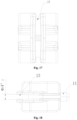
- the present embodiment introduces a joint 5 of the air duct connecting beam 2, the joint 5 is respectively placed and fixed in a hollow part 8 at two ends of the connecting beam 2 of the air duct, a clamping hole 14 is arranged in the joint 5, the motor 1 and the adaptor 3 are respectively connected with the joint 5 in an inserting manner through a clamping hole 14, the adaptor 3 is connected with the first joint 21 in an inserting manner, and the motor 1 is connected with the second joint 22 in an inserting manner.
- the connecting beam 2 includes a substrate 7 and a hollow part 8, the hollow part 8 is arranged at a left end and a right end of the substrate 7, the hollow part 8 is internally installed with a joint 5 and a spring 6, such that the motor 1 and the adaptor 3 are connected with the connecting beam 2.
- the hollow part 8 is set to be stair-stepping along an axis, and includes a large caliber part and a small caliber part, wherein the caliber of the large caliber part is larger than the caliber of the small caliber part, and the large caliber part is matched with the joint 5.
- One end, far away from the small caliber part, of the hollow part 8 is provided with a spring extending head 15 protruding outwards, to install the spring 6.
- the front part of the joint 5 is transited in an arc shape, the upper and lower ends of the middle part of the joint 5 are respectively provided with a fixed boss 12 which protrudes outwards, the front part of the joint 5 is disconnected along an axis direction, and the front part and the rear part of the fixed boss 12 are both provided with two axially symmetrical claws, to control the opening and closing of the front part of the joint 5.
- the periphery of the joint 5 is concave inwards to form a groove 13, the groove 13 is matched with the small caliber part of the hollow part 8, such that the joint 5 is connected with the substrate 7 in an inserting manner through the groove 13, and the arc-shaped front part of the joint 5 enables the inserting connection between the joint 5 and the substrate 7 to be tighter, thereby facilitating the installation and disassembly of the j oint.
- the spacing between two side walls of the groove 13 is gradually decreased from the front part of the joint 5 to the middle part, and the inclined angle between the two side walls is 4 degrees.
- the rear part of the joint 5 is provided with a spring installation joint 11, the spring installation joint 11 is corresponding to the spring extending head 15 of the hollow part 8, one end of the spring is connected with the spring installation joint 11 of the joint 5, the other end is connected with the spring extending head 15 of the hollow part 8, the inserting connection between the joint 5 and the substrate 7 is strengthened by utilizing a spring force, to prevent accidental falling off of the joint 5.
- the middle part of the joint 5 is provided with a clamping hole 14, the clamping hole 14 is of a cylindrical structure, the clamping hole 14 is arranged vertically, and penetrates through the middle part of the whole joint 5 vertically, a notch 10 which is concave towards the front end is arranged at the front end, close to the joint 5, of the clamping hole 14, and the notch 10 and the clamping hole 14 are both arranged to be co-axial with the joint 5.
- the middle position of the inner wall of the clamping hole 14 is provided with multiple bulges 10 which are arranged in a circumferential direction and which protrude outwards, multiple bulges 10 are uniformly distributed, and are arranged on the same height, and the setting of the bulges 10 can facilitate the installation and dead lock of the motor 1 and the adaptor 3 and the joint 5.
- the present embodiment introduces a connecting beam 2 of an air duct conversion device 200, and the connecting beam 2 includes a substrate 7, a joint 5, and a spring 6; two ends of the substrate 7 are respectively provided with a hollow part 8 configured to place the joint 5 and the spring 6, the periphery of the joint 5 is provided with a groove 13, the joint 5 is provided with a clamping hole 14 vertical to the groove 13, and two ends of the spring are respectively sleeved on the joint 5 and the substrate 7, to limit the joint 5.
- the joint 5 and the spring 6 are placed and fixed at two ends of the substrate 7, two joints 5 are respectively connected with the motor 1 and the adaptor 3, the first joint 21 and the coupling shaft 31 of the adaptor 3 are in inserting connection and fixation in a manner of capable of rotating around a shaft, the second joint 22 and the output shaft of the motor 1 is in inserting connection and fixation in a manner of capable of relatively rotating around a shaft, the adaptor 3 is connected with the air duct baffle 4, such that the motor 1 and the air duct baffle 4 are connected with the connecting beam 2, the motor 1 drives the connecting beam 2 to rotate, to further drive the adaptor 3 and the air duct baffle 4 to rotate, and realize the opening and closing of the air duct.
- the substrate 7 is of a rectangle shape, the left and right ends of the substrate 7 are respectively transited in an arc shape, the left and right ends of the substrate 7 are provided with a hollow part 8, the joint 5 and the spring 6 are placed in the hollow part 8, and are fixedly connected with the substrate 7, such that the motor 1 and the air duct baffle 4 are connected with the connecting beam 2.
- the hollow part 8 is set to be stair-stepping along an axis, and includes in sequence a small caliber part 18, a large caliber part 19 and a connecting part 20, the caliber of the small caliber part 18 is smaller than the caliber of the large caliber part 19, the shape of the large caliber part 19 is matched with the joint 5, the side wall of the joint 5 is provided with a groove 13, the shape of the small caliber side is matched with the groove 13 of the joint 5; and the connecting part 20 is provided with a spring extending head 15 protruding towards the direction of the small caliber part 18, to install the spring 6.
- the middle position of the substrate 7 is provided with a reinforcing bulge 16 which protrudes outwards, the reinforcing bulge 16 is trapezoidal, the periphery of the substrate 7 is folded downwards to form a folded edge 17, to strengthen the intensity of the substrate 7, and when the motor 1 drives the connecting beam 2 to rotate, the substrate 7 will not deform.
- the front part of the joint 5 is transited in an arc shape, the upper and lower ends of the middle part are respectively provided with a fixed boss 12 which protrudes outwards, such that the thickness of the joint 5 is larger than the thickness of the substrate 7.
- the middle part of the side wall of the joint 5 is concave inwards to form a groove 13, the groove 13 is matched with the small caliber part 18 of the hollow part 8, such that the joint 5 is connected with the substrate 7 in an inserting manner through the groove 13, and the arc-shaped front part of the joint 5 enables the inserting connection between the joint 5 and the substrate 7 to be tighter, thereby facilitating the installation and disassembly of the joint 5.
- the rear end of the joint 5 is provided with a spring installation joint 11 which protrudes outwards along an axis, the spring extending head 15 of the connecting part 20 is corresponding to the installation joint of the spring 6.
- One end of the spring 6 is sleeved on the spring installation joint 11 of the joint 5, and is abutted against the rear end of the joint 5, the other end is sleeved on the spring extending head 15 of the hollow part 8 and is abutted against the substrate 7, such that the inserting connection between the joint 5 and the substrate 7 under the effect of a spring is tighter, and falling off of the joint 5 is prevented.
- the installation manner between the joint 5 and the connecting beam 2 includes the following steps:
- one end of the compressed spring 6 is installed on the spring installation joint 11 of the joint 5, the other end is installed on the protruding spring extending head 15 of the connecting part 20, and the joint 5 is limited through a tension of the compressed spring 6.
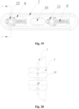
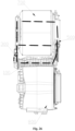
- the present embodiment introduces a clothing treating device which includes a first clothing treating bucket 700 and a second clothing treating bucket 800, the first clothing treating bucket 700 and the second clothing treating bucket 800 are respectively provided with a clothes delivery opening, to deliver to-be-treated clothes to the first clothing treating bucket 700 and the second clothing treating bucket 800 respectively.
- the first clothing treating bucket 700 and/or the second clothing treating bucket 800 can only possess a drying function, and can also possess a drying function and a washing function simultaneously; of course, under the premise of possessing a drying function and a washing function, other clothing treating functions can also be integrated, such as a steam washing function, an ultraviolet anti-virus function.
- a single air duct can provide a circulating air flow for drying clothes to the first clothing treating bucket or the second clothing treating bucket, respectively, thereby further achieving the purpose of sharing one air duct by two sets of clothing drying equipment, and achieving the purpose of sharing the same clothing drying air duct on the clothing treating device possessing two sets of clothing treating equipment.
- the clothing treating device is further provided with an air duct 100
- the air inlet end of the air duct 100 is respectively communicated with the first air inlet 300 of the first clothing treating bucket 700 and the second air inlet 400 of the second clothing treating bucket 800 through an air duct conversion device 210 at the air inlet end
- the air duct conversion device 220 at the air outlet end of the air duct 100 is respectively communicated with the first air outlet 500 of the first clothing treating bucket 700 and the second air outlet 600 of the second clothing treating bucket 800.
- the air duct conversion device 210 at the air inlet end and the air duct conversion device 220 at the air outlet end are both constituted by the air duct conversion device 200 of any of the above embodiments 1-5
- the air duct conversion device 200 includes an air duct baffle 4 which is installed on the air duct in a manner of capable of rotating relatively.
- the output shaft of the motor 1 is connected with the air duct baffle 4 through a linkage mechanism, to drive the air duct baffle 4 to rotate around a shaft through a linkage mechanism in the rotating process of the output shaft of the motor 1, such that the air duct baffle 4 switches to move between the first position and the second position.
- the first air inlet 300 is closed and the second air inlet 400 is open
- the first air outlet 500 is closed and the second air outlet 600 is open
- the first air inlet 300 is open and the second air inlet 400 is closed
- the first air outlet 500 is open and the second air outlet 600 is closed.
- the first clothing treating bucket 700 is arranged above the second clothing treating bucket 800, the air duct 100 is arranged horizontally between the first clothing treating bucket 700 and the second clothing treating bucket 800.
- the axis of the first clothing treating bucket 700 is set to be in parallel with the axis of the second clothing treating bucket 800, and clothes delivery openings of the two are both arranged at the same end, and the end of the air duct 100 at the clothes delivery opening side is the air outlet end, and the end of the air duct 100 relatively far away from the clothes delivery opening side is the air inlet end.
- the air inlet end of the air duct 100 is provided with a first air inlet 300 communicated upwards with the first clothing treating bucket 700, and a second air inlet 400 communicated downwards with the second clothing treating bucket 800.
- the air duct conversion device 210 at the air inlet end is installed in the middle of the air inlet end of the air duct 100, such that the first air inlet 300 is correspondingly closed when the air duct baffle 4 of the air duct conversion device 210 at the air inlet end rotates upwards to the first position, and the second air inlet 400 is correspondingly closed when the air duct baffle 4 of the air duct conversion device 210 at the air inlet end rotates downwards to the second position.
- the air outlet end of the air duct 100 is provided with a first air outlet 500 communicated upwards with the first clothing treating bucket 700, and a second air outlet 600 communicated downwards with the second clothing treating bucket 800, the air duct conversion device 220 at the air outlet end is installed in the middle of the air outlet end of the air duct 100, such that the first air outlet 500 is correspondingly closed when the air duct baffle 4 of the air duct conversion device 220 at the air outlet end rotates upwards to the first position, and the second air outlet 600 is correspondingly closed when the air duct baffle 4 of the air duct conversion device 220 at the air outlet end rotates downwards to the second position.
- the air duct 100 is successively internally installed with, along the direction of an air flow, a condensing device for condensing the air flow that flows through, and a heating device for heating the air flow that flows through.
- a condensing device for condensing the air flow that flows through
- a heating device for heating the air flow that flows through.
- the air duct baffle 4 of the air duct converting device 210 at the air inlet end and the air duct baffle 4 of the air duct conversion device 220 at the air outlet end are both arranged at the second position, such that the air duct 100 and the first clothing treating device 700 form a circulating channel.
- the air duct baffle 4 of the air duct converting device 210 at the air inlet end and the air duct baffle 4 of the air duct conversion device 220 at the air outlet end are both arranged at the first position, such that the air duct 100 and the second clothing treating device 800 form a circulating channel.
Landscapes
- Engineering & Computer Science (AREA)
- Textile Engineering (AREA)
- Detail Structures Of Washing Machines And Dryers (AREA)
- Air-Flow Control Members (AREA)
- Accessory Of Washing/Drying Machine, Commercial Washing/Drying Machine, Other Washing/Drying Machine (AREA)
- Professional, Industrial, Or Sporting Protective Garments (AREA)
- Main Body Construction Of Washing Machines And Laundry Dryers (AREA)
Claims (10)
- Un dispositif de traitement de vêtements, comprenant une première cuve de traitement de vêtements (700), une deuxième cuve de traitement de vêtements (800) et un conduit d'air (100), dans lequelune extrémité d'entrée d'air du conduit d'air (100) communique respectivement avec une première entrée d'air (300) de la première cuve de traitement de vêtements (700) et une deuxième entrée d'air (400) de la deuxième cuve de traitement de vêtements (800) par un premier dispositif de commutation de conduit d'air (210) au niveau de l'extrémité d'entrée d'air, etune extrémité de sortie d'air du conduit d'air (100) communique respectivement avec une première sortie d'air (500) de la première cuve de traitement de vêtements (700) et une deuxième sortie d'air (600) de la deuxième cuve de traitement de vêtements (800) par un deuxième dispositif de commutation de conduit d'air (220) au niveau de l'extrémité de sortie d'air du conduit d'air (100).
- Le dispositif de traitement de vêtements selon la revendication 1, dans lequel chacun des premiers dispositifs de commutation de conduit d'air (210) et le deuxième dispositif de commutation de conduit d'air (220) comprenant un déflecteur de conduit d'air (4) installé dans le conduit d'air (100) de manière à pouvoir tourner relativement;
un arbre de sortie d'un moteur (1) est relié au déflecteur de conduit d'air (4) par l'intermédiaire d'un mécanisme de liaison, pour entraîner la rotation du déflecteur de conduit d'air (4) à travers le mécanisme de liaison dans un processus rotatif de l'arbre de sortie du moteur (1), de sorte que le déflecteur de conduit d'air (4) soit configuré de manière à basculer entre une première position et une deuxième position. - Le dispositif de traitement de vêtements selon la revendication 2, dans lequel la première position du déflecteur de conduit d'air (4) du dispositif de commutation de conduit d'air (210) au niveau de l'extrémité d'entrée d'air correspond à une position où la première entrée d'air (300) est fermée et la deuxième entrée d'air (400) est ouverte,la première position du déflecteur de conduit d'air (4) du dispositif de commutation de conduit d'air (220) au niveau de l'extrémité de sortie d'air correspond à une position où la première sortie d'air (500) est fermée et la deuxième sortie d'air (600) est ouverte,la deuxième position du déflecteur de conduit d'air (4) du dispositif de commutation de conduit d'air (210) au niveau de l'extrémité d'entrée d'air correspond à une position où la première entrée d'air (300) est ouverte et la deuxième entrée d'air (400) est fermée, etla deuxième position du déflecteur de conduit d'air (4) du dispositif de commutation de conduit d'air (220) au niveau de l'extrémité de sortie d'air correspond à une position où la première sortie d'air (500) est ouverte et la deuxième sortie d'air (600) est fermée.
- Le dispositif de traitement de vêtements selon l'une quelconque des revendications 1 à 3, dans lequel la première cuve de traitement de vêtements (700) est disposée au-dessus de la deuxième cuve de traitement de vêtements (800), le conduit d'air (100) est disposé horizontalement entre la première cuve de traitement de vêtements (700) et la deuxième cuve de traitement de vêtements (800);un axe de la première cuve de traitement de vêtements (700) est réglé de manière à être parallèle à un axe de la deuxième cuve de traitement de vêtements (800), et des ouvertures de décharge des vêtements da la première cuve de traitement de vêtements (700) et de la deuxième cuve de traitement de vêtements (800) sont toutes deux disposées du même côté, etl'extrémité de sortie d'air du côté de l'ouverture de décharge des vêtements et l'extrémité d'entrée d'air sont relativement éloignées du côté de l'ouverture de décharge des vêtements.
- Le dispositif de traitement de vêtements selon la revendication 4, dans lequel l'extrémité d'entrée d'air du conduit d'air (100) est pourvue respectivement de la première entrée d'air (300) qui communique avec la première cuve de traitement de vêtements (700) vers le haut, et la deuxième entrée d'air (400) qui communique avec la deuxième cuve de traitement de vêtements (800) vers le bas,le dispositif de commutation de conduit d'air (200) au niveau de l'extrémité d'entrée d'air est installé au milieu de l'extrémité d'entrée d'air du conduit d'air (100),la première entrée d'air (300) est fermée par conséquent lorsque le déflecteur de conduit d'air (4) du dispositif de commutation de conduit d'air (210) au niveau de l'extrémité d'entrée d'air est tourné vers le haut à la première position, etla deuxième entrée d'air (400) est par conséquent fermée lorsque le déflecteur de conduit d'air (4) du dispositif de commutation de conduit d'air (210) au niveau de l'extrémité d'entrée d'air est tourné vers le bas à la seconde position; etl'extrémité de sortie d'air du conduit d'air (100) est respectivement pourvue de la première sortie d'air (500) qui communique avec la première cuve de traitement de vêtements (700) vers le haut, et la deuxième sortie d'air (600) qui communique avec la deuxième cuve de traitement de vêtements (800) vers le bas,le dispositif de commutation de conduit d'air (220) à l'extrémité de sortie d'air est installé au milieu de l'extrémité de sortie d'air du conduit d'air (100),la première sortie d'air (500) est fermée par conséquent lorsque le déflecteur de conduit d'air (4) du dispositif de commutation de conduit d'air (220) à l'extrémité de sortie d'air est tourné vers le haut à la première position, et la deuxième sortie d'air (600) est fermée par conséquent lorsque le déflecteur de conduit d'air (4) du dispositif de commutation de conduit d'air (220) à l'extrémité de la sortie d'air est tourné vers le bas à la deuxième position.
- Le dispositif de traitement de vêtements selon l'une quelconque des revendications 1 à 5, dans lequel le conduit d'air (100) est successivement installé à l'intérieur avec, le long d'une direction d'un flux d'air, un dispositif de condensation pour condenser le flux d'air qui circule à travers, et un dispositif de chauffage pour chauffer le flux d'air qui circule à travers.
- Le dispositif de traitement de vêtements selon l'une quelconque des revendications 1 à 6, dans lequel lorsque la première cuve de traitement de vêtements (700) a entamé le processus de séchage des vêtements, le déflecteur de conduit d'air (4) du dispositif de commutation de conduit d'air (210) à l'extrémité d'entrée d'air et le déflecteur de conduit d'air (4) du dispositif de commutation de conduit d'air (220) à l'extrémité de la sortie d'air sont tous deux situés en deuxième position, de sorte que l'air puisse circuler entre le conduit d'air (100) et le premier dispositif de traitement de vêtements; et
lorsque la deuxième cuve de traitement de vêtements (800) a entamé le processus de séchage des vêtements, le déflecteur de conduit air (4) du dispositif de commutation de conduit d'air (210) à l'extrémité d'entrée d'air et le déflecteur de conduit d'air (4) du dispositif de commutation de conduit d'air (220) à l'extrémité de sortie d'air sont tous deux situés en première position, de sorte que l'air puisse circuler entre le conduit d'air (100) et le deuxième dispositif de traitement de vêtements. - Le dispositif de traitement de vêtements selon la revendication 2, dans lequel le mécanisme de liaison comprend un adaptateur (3) et un élément de raccordement (2) qui sont reliés de manière à pouvoir tourner relativement, l'élément de raccordement (2) est en liaison d'insertion avec l'arbre de sortie du moteur (1) de manière à pouvoir tourner relativement autour de l'arbre de sortie du moteur (1), et l'adaptateur (3) est en liaison d'insertion avec l'arbre de déflecteur (411) du déflecteur de conduit d'air (4) d'une manière à pouvoir tourner relativement; et
de préférence, une extrémité du déflecteur de conduit d'air (4) est pourvue d'un arbre de déflecteur (411) s'étendant horizontalement vers deux côtés, l'arbre de déflecteur (411) est inséré et fixé à deux parois latérales (101) du conduit d'air (100) en conséquence, le déflecteur est installé dans le conduit d'air (100) d'une manière à pouvoir tourner relativement; et une extrémité de l'arbre de déflecteur (411) pénètre à travers le conduit d'air (100) et est reliée de manière fixe à l'adaptateur (3). - Le dispositif de traitement de vêtements selon la revendication 8, dans lequel l'arbre de sortie du moteur (1) est d'une structure d'arbre excentrique,
la structure d'arbre excentrique comprend une partie d'arbre excentrique (111) qui tourne autour d'un centre moteur, la partie d'arbre excentrique (111) et l'élément de raccordement (2) sont en liaison d'insertion et de fixation l'un avec l'autre de manière à pouvoir tourner relativement, pour entraîner l'élément de raccordement (2) à se déplacer dans le processus de rotation de la partie d'arbre excentrique (111), et en outre amener le déflecteur de conduit d'air (4) à tourner autour de l'arbre de déflecteur (411) via l'adaptateur (3). - Le dispositif de traitement de vêtements selon la revendication 2, dans lequel une paroi latérale (101) du conduit d'air (100) est pourvue d'une rainure d'installation (203), la rainure d'installation (203) est installée de manière fixe à l'intérieur avec un manchon de support (204) avec une périphérie non circulaire, et le manchon de support (204) est pourvu d'un orifice d'installation (205) pour insérer l'arbre de déflecteur (411) du déflecteur de conduit d'air (4) en conséquence.
Applications Claiming Priority (2)
| Application Number | Priority Date | Filing Date | Title |
|---|---|---|---|
| CN201810102473.0A CN110106675B (zh) | 2018-02-01 | 2018-02-01 | 一种衣物处理装置 |
| PCT/CN2019/074117 WO2019149241A1 (fr) | 2018-02-01 | 2019-01-31 | Dispositif de traitement de vêtements |
Publications (4)
| Publication Number | Publication Date |
|---|---|
| EP3748062A1 EP3748062A1 (fr) | 2020-12-09 |
| EP3748062A4 EP3748062A4 (fr) | 2020-12-09 |
| EP3748062B1 true EP3748062B1 (fr) | 2023-11-22 |
| EP3748062C0 EP3748062C0 (fr) | 2023-11-22 |
Family
ID=67479604
Family Applications (1)
| Application Number | Title | Priority Date | Filing Date |
|---|---|---|---|
| EP19747563.5A Active EP3748062B1 (fr) | 2018-02-01 | 2019-01-31 | Dispositif de traitement de vêtements |
Country Status (6)
| Country | Link |
|---|---|
| US (1) | US11976407B2 (fr) |
| EP (1) | EP3748062B1 (fr) |
| JP (1) | JP2021513393A (fr) |
| KR (1) | KR102390610B1 (fr) |
| CN (1) | CN110106675B (fr) |
| WO (1) | WO2019149241A1 (fr) |
Families Citing this family (6)
| Publication number | Priority date | Publication date | Assignee | Title |
|---|---|---|---|---|
| CN114855412B (zh) * | 2019-10-10 | 2023-11-03 | 无锡小天鹅电器有限公司 | 衣物处理装置 |
| CN114836935B (zh) * | 2019-10-10 | 2023-11-03 | 无锡小天鹅电器有限公司 | 衣物处理装置 |
| CN110761028B (zh) * | 2019-10-10 | 2023-06-30 | 无锡小天鹅电器有限公司 | 衣物处理装置 |
| CN114182501A (zh) * | 2020-09-15 | 2022-03-15 | 青岛海尔滚筒洗衣机有限公司 | 烘干设备 |
| CN116623408A (zh) * | 2022-06-22 | 2023-08-22 | 湖北美的洗衣机有限公司 | 风道壳组件和衣物处理装置 |
| CN117845500B (zh) * | 2023-12-29 | 2025-09-23 | 珠海格力电器股份有限公司 | 双筒衣物处理设备及烘干方法 |
Family Cites Families (27)
| Publication number | Priority date | Publication date | Assignee | Title |
|---|---|---|---|---|
| US3555701A (en) * | 1969-05-15 | 1971-01-19 | Philco Ford Corp | Laundry apparatus |
| JP2001198396A (ja) * | 2000-01-24 | 2001-07-24 | Hitachi Ltd | 衣類乾燥機 |
| KR100662364B1 (ko) * | 2004-11-01 | 2007-01-02 | 엘지전자 주식회사 | 세탁 및 건조 장치 |
| KR100652459B1 (ko) * | 2005-11-25 | 2006-12-01 | 엘지전자 주식회사 | 일체형 세탁 건조기 |
| JP4996202B2 (ja) * | 2006-10-31 | 2012-08-08 | 株式会社東芝 | 洗濯乾燥機 |
| JP4811328B2 (ja) * | 2007-04-12 | 2011-11-09 | 三菱電機株式会社 | 空気調和機 |
| JP2008284142A (ja) * | 2007-05-17 | 2008-11-27 | Toshiba Corp | 衣類乾燥機 |
| CA2640840C (fr) * | 2007-10-09 | 2016-01-26 | Oy Halton Group Ltd. | Regulateur approprie pour ecoulements charges en aerosol liquide |
| CN101319457A (zh) * | 2008-06-24 | 2008-12-10 | 赵大勇 | 衣物烘干机和双层洗脱烘一体机 |
| CN102517859B (zh) * | 2011-12-12 | 2017-09-22 | 青岛海尔滚筒洗衣机有限公司 | 滚筒式洗干一体机及烘干控制方法 |
| JP5885202B2 (ja) * | 2012-03-30 | 2016-03-15 | 株式会社ケーヒン | シール付き転がり軸受 |
| DE102014203071B4 (de) * | 2013-02-28 | 2018-11-29 | Lg Electronics Inc. | Wäschebehandlungsvorrichtung |
| KR102118045B1 (ko) * | 2013-03-19 | 2020-06-02 | 엘지전자 주식회사 | 의류처리장치 |
| JP2015051178A (ja) * | 2013-09-09 | 2015-03-19 | パナソニック株式会社 | 洗濯乾燥機 |
| CN105316919B (zh) | 2014-08-01 | 2019-07-23 | 青岛海尔滚筒洗衣机有限公司 | 一种滚筒干衣机及干衣方法 |
| CN105568648A (zh) * | 2014-10-15 | 2016-05-11 | 青岛胶南海尔洗衣机有限公司 | 一种干衣机控制方法及干衣机 |
| CN105177915B (zh) | 2015-06-30 | 2018-06-19 | 无锡小天鹅股份有限公司 | 滚筒洗衣机 |
| CN107190459A (zh) * | 2016-03-15 | 2017-09-22 | 杭州三花家电热管理系统有限公司 | 衣物处理装置及其控制方法 |
| JP6700999B2 (ja) * | 2016-06-22 | 2020-05-27 | アズビル株式会社 | 可変風量装置 |
| CN106350978B (zh) * | 2016-08-31 | 2020-05-19 | 无锡小天鹅电器有限公司 | 热泵式干衣机及其烘干控制方法 |
| CN108950976A (zh) * | 2017-05-27 | 2018-12-07 | 青岛海尔滚筒洗衣机有限公司 | 衣物处理设备 |
| CN108085941A (zh) * | 2018-01-02 | 2018-05-29 | 珠海格力电器股份有限公司 | 烘干系统、洗涤烘干一体机及其控制方法 |
| CN208038875U (zh) * | 2018-02-01 | 2018-11-02 | 青岛海尔滚筒洗衣机有限公司 | 一种风道转换装置及衣物处理装置 |
| CN208151723U (zh) * | 2018-02-01 | 2018-11-27 | 青岛海尔滚筒洗衣机有限公司 | 一种风道转换装置的连接横梁及风道转换装置 |
| CN208038870U (zh) * | 2018-02-01 | 2018-11-02 | 青岛海尔滚筒洗衣机有限公司 | 一种衣物处理装置 |
| CN208151722U (zh) * | 2018-02-01 | 2018-11-27 | 青岛海尔滚筒洗衣机有限公司 | 一种风道转换装置的风道挡板及风道转换装置 |
| CN208038878U (zh) * | 2018-02-01 | 2018-11-02 | 青岛海尔滚筒洗衣机有限公司 | 一种风道连接横梁的接头及风道转换装置 |
-
2018
- 2018-02-01 CN CN201810102473.0A patent/CN110106675B/zh active Active
-
2019
- 2019-01-31 US US16/967,061 patent/US11976407B2/en active Active
- 2019-01-31 WO PCT/CN2019/074117 patent/WO2019149241A1/fr not_active Ceased
- 2019-01-31 KR KR1020207025111A patent/KR102390610B1/ko active Active
- 2019-01-31 JP JP2020542125A patent/JP2021513393A/ja active Pending
- 2019-01-31 EP EP19747563.5A patent/EP3748062B1/fr active Active
Also Published As
| Publication number | Publication date |
|---|---|
| EP3748062A1 (fr) | 2020-12-09 |
| KR20200138716A (ko) | 2020-12-10 |
| EP3748062A4 (fr) | 2020-12-09 |
| EP3748062C0 (fr) | 2023-11-22 |
| CN110106675A (zh) | 2019-08-09 |
| WO2019149241A1 (fr) | 2019-08-08 |
| US11976407B2 (en) | 2024-05-07 |
| KR102390610B1 (ko) | 2022-04-26 |
| JP2021513393A (ja) | 2021-05-27 |
| US20210047771A1 (en) | 2021-02-18 |
| CN110106675B (zh) | 2024-08-27 |
Similar Documents
| Publication | Publication Date | Title |
|---|---|---|
| US12071720B2 (en) | Air duct conversion device and clothing treating device | |
| US11976407B2 (en) | Clothing treating device | |
| CN208038870U (zh) | 一种衣物处理装置 | |
| EP3399093B1 (fr) | Machine à laver et à sécher intégrée | |
| CN208038878U (zh) | 一种风道连接横梁的接头及风道转换装置 | |
| CN208151723U (zh) | 一种风道转换装置的连接横梁及风道转换装置 | |
| CN215887650U (zh) | 干衣机 | |
| CN208151722U (zh) | 一种风道转换装置的风道挡板及风道转换装置 | |
| CN208038875U (zh) | 一种风道转换装置及衣物处理装置 | |
| CN208041159U (zh) | 一种风道转换装置用转接件及风道转换装置 | |
| CN208038879U (zh) | 一种供风道转换装置安装的轴套结构及风道转换装置 | |
| CN110106682B (zh) | 一种风道转换装置的连接横梁及风道转换装置 | |
| CN110106678B (zh) | 一种风道连接横梁的接头及风道转换装置 | |
| CN110106677B (zh) | 一种供风道转换装置安装的轴套结构及风道转换装置 | |
| CN110107696B (zh) | 一种风道转换装置用转接件及风道转换装置 | |
| KR20040023999A (ko) | 의류건조기의 모터축 구조 | |
| CN110106680A (zh) | 一种风道转换装置的风道挡板及风道转换装置 | |
| CN114045629B (zh) | 一种具有烘干功能的滚筒洗衣机 | |
| CN114753087B (zh) | 一种具有热泵烘干功能的衣物处理装置 | |
| CN114836958B (zh) | 一种冷凝式波轮洗烘一体机 | |
| CN116949738A (zh) | 一种具有烘干组件的机盖以及均匀烘干的洗衣机 | |
| CN213447728U (zh) | 一种具有风门启闭功能的干衣机 | |
| CN103306113A (zh) | 洗衣干衣机 | |
| CN118461273A (zh) | 一种具有烘干功能的衣物处理装置 | |
| CN118461293A (zh) | 一种风道结构及具有烘干功能的衣物处理装置 |
Legal Events
| Date | Code | Title | Description |
|---|---|---|---|
| STAA | Information on the status of an ep patent application or granted ep patent |
Free format text: STATUS: THE INTERNATIONAL PUBLICATION HAS BEEN MADE |
|
| PUAI | Public reference made under article 153(3) epc to a published international application that has entered the european phase |
Free format text: ORIGINAL CODE: 0009012 |
|
| STAA | Information on the status of an ep patent application or granted ep patent |
Free format text: STATUS: REQUEST FOR EXAMINATION WAS MADE |
|
| 17P | Request for examination filed |
Effective date: 20200828 |
|
| A4 | Supplementary search report drawn up and despatched |
Effective date: 20201019 |
|
| AK | Designated contracting states |
Kind code of ref document: A1 Designated state(s): AL AT BE BG CH CY CZ DE DK EE ES FI FR GB GR HR HU IE IS IT LI LT LU LV MC MK MT NL NO PL PT RO RS SE SI SK SM TR |
|
| AX | Request for extension of the european patent |
Extension state: BA ME |
|
| DAV | Request for validation of the european patent (deleted) | ||
| DAX | Request for extension of the european patent (deleted) | ||
| RIC1 | Information provided on ipc code assigned before grant |
Ipc: D06F 58/30 20200101ALN20230405BHEP Ipc: D06F 58/20 20060101ALN20230405BHEP Ipc: D06F 29/00 20060101ALN20230405BHEP Ipc: D06F 58/02 20060101AFI20230405BHEP |
|
| GRAP | Despatch of communication of intention to grant a patent |
Free format text: ORIGINAL CODE: EPIDOSNIGR1 |
|
| STAA | Information on the status of an ep patent application or granted ep patent |
Free format text: STATUS: GRANT OF PATENT IS INTENDED |
|
| RIC1 | Information provided on ipc code assigned before grant |
Ipc: D06F 58/30 20200101ALN20230504BHEP Ipc: D06F 58/20 20060101ALN20230504BHEP Ipc: D06F 29/00 20060101ALN20230504BHEP Ipc: D06F 58/02 20060101AFI20230504BHEP |
|
| RIC1 | Information provided on ipc code assigned before grant |
Ipc: D06F 58/30 20200101ALN20230509BHEP Ipc: D06F 58/20 20060101ALN20230509BHEP Ipc: D06F 29/00 20060101ALN20230509BHEP Ipc: D06F 58/02 20060101AFI20230509BHEP |
|
| INTG | Intention to grant announced |
Effective date: 20230605 |
|
| GRAS | Grant fee paid |
Free format text: ORIGINAL CODE: EPIDOSNIGR3 |
|
| GRAA | (expected) grant |
Free format text: ORIGINAL CODE: 0009210 |
|
| STAA | Information on the status of an ep patent application or granted ep patent |
Free format text: STATUS: THE PATENT HAS BEEN GRANTED |
|
| AK | Designated contracting states |
Kind code of ref document: B1 Designated state(s): AL AT BE BG CH CY CZ DE DK EE ES FI FR GB GR HR HU IE IS IT LI LT LU LV MC MK MT NL NO PL PT RO RS SE SI SK SM TR |
|
| REG | Reference to a national code |
Ref country code: GB Ref legal event code: FG4D |
|
| REG | Reference to a national code |
Ref country code: CH Ref legal event code: EP |
|
| REG | Reference to a national code |
Ref country code: DE Ref legal event code: R096 Ref document number: 602019041907 Country of ref document: DE |
|
| REG | Reference to a national code |
Ref country code: IE Ref legal event code: FG4D |
|
| U01 | Request for unitary effect filed |
Effective date: 20231215 |
|
| U07 | Unitary effect registered |
Designated state(s): AT BE BG DE DK EE FI FR IT LT LU LV MT NL PT SE SI Effective date: 20231222 |
|
| U20 | Renewal fee for the european patent with unitary effect paid |
Year of fee payment: 6 Effective date: 20240131 |
|
| PG25 | Lapsed in a contracting state [announced via postgrant information from national office to epo] |
Ref country code: GR Free format text: LAPSE BECAUSE OF FAILURE TO SUBMIT A TRANSLATION OF THE DESCRIPTION OR TO PAY THE FEE WITHIN THE PRESCRIBED TIME-LIMIT Effective date: 20240223 |
|
| PG25 | Lapsed in a contracting state [announced via postgrant information from national office to epo] |
Ref country code: IS Free format text: LAPSE BECAUSE OF FAILURE TO SUBMIT A TRANSLATION OF THE DESCRIPTION OR TO PAY THE FEE WITHIN THE PRESCRIBED TIME-LIMIT Effective date: 20240322 |
|
| PG25 | Lapsed in a contracting state [announced via postgrant information from national office to epo] |
Ref country code: ES Free format text: LAPSE BECAUSE OF FAILURE TO SUBMIT A TRANSLATION OF THE DESCRIPTION OR TO PAY THE FEE WITHIN THE PRESCRIBED TIME-LIMIT Effective date: 20231122 |
|
| PG25 | Lapsed in a contracting state [announced via postgrant information from national office to epo] |
Ref country code: IS Free format text: LAPSE BECAUSE OF FAILURE TO SUBMIT A TRANSLATION OF THE DESCRIPTION OR TO PAY THE FEE WITHIN THE PRESCRIBED TIME-LIMIT Effective date: 20240322 Ref country code: GR Free format text: LAPSE BECAUSE OF FAILURE TO SUBMIT A TRANSLATION OF THE DESCRIPTION OR TO PAY THE FEE WITHIN THE PRESCRIBED TIME-LIMIT Effective date: 20240223 Ref country code: ES Free format text: LAPSE BECAUSE OF FAILURE TO SUBMIT A TRANSLATION OF THE DESCRIPTION OR TO PAY THE FEE WITHIN THE PRESCRIBED TIME-LIMIT Effective date: 20231122 |
|
| PG25 | Lapsed in a contracting state [announced via postgrant information from national office to epo] |
Ref country code: RS Free format text: LAPSE BECAUSE OF FAILURE TO SUBMIT A TRANSLATION OF THE DESCRIPTION OR TO PAY THE FEE WITHIN THE PRESCRIBED TIME-LIMIT Effective date: 20231122 Ref country code: PL Free format text: LAPSE BECAUSE OF FAILURE TO SUBMIT A TRANSLATION OF THE DESCRIPTION OR TO PAY THE FEE WITHIN THE PRESCRIBED TIME-LIMIT Effective date: 20231122 Ref country code: NO Free format text: LAPSE BECAUSE OF FAILURE TO SUBMIT A TRANSLATION OF THE DESCRIPTION OR TO PAY THE FEE WITHIN THE PRESCRIBED TIME-LIMIT Effective date: 20240222 Ref country code: HR Free format text: LAPSE BECAUSE OF FAILURE TO SUBMIT A TRANSLATION OF THE DESCRIPTION OR TO PAY THE FEE WITHIN THE PRESCRIBED TIME-LIMIT Effective date: 20231122 |
|
| PG25 | Lapsed in a contracting state [announced via postgrant information from national office to epo] |
Ref country code: CZ Free format text: LAPSE BECAUSE OF FAILURE TO SUBMIT A TRANSLATION OF THE DESCRIPTION OR TO PAY THE FEE WITHIN THE PRESCRIBED TIME-LIMIT Effective date: 20231122 |
|
| PG25 | Lapsed in a contracting state [announced via postgrant information from national office to epo] |
Ref country code: SK Free format text: LAPSE BECAUSE OF FAILURE TO SUBMIT A TRANSLATION OF THE DESCRIPTION OR TO PAY THE FEE WITHIN THE PRESCRIBED TIME-LIMIT Effective date: 20231122 |
|
| PG25 | Lapsed in a contracting state [announced via postgrant information from national office to epo] |
Ref country code: SM Free format text: LAPSE BECAUSE OF FAILURE TO SUBMIT A TRANSLATION OF THE DESCRIPTION OR TO PAY THE FEE WITHIN THE PRESCRIBED TIME-LIMIT Effective date: 20231122 Ref country code: SK Free format text: LAPSE BECAUSE OF FAILURE TO SUBMIT A TRANSLATION OF THE DESCRIPTION OR TO PAY THE FEE WITHIN THE PRESCRIBED TIME-LIMIT Effective date: 20231122 Ref country code: RO Free format text: LAPSE BECAUSE OF FAILURE TO SUBMIT A TRANSLATION OF THE DESCRIPTION OR TO PAY THE FEE WITHIN THE PRESCRIBED TIME-LIMIT Effective date: 20231122 Ref country code: CZ Free format text: LAPSE BECAUSE OF FAILURE TO SUBMIT A TRANSLATION OF THE DESCRIPTION OR TO PAY THE FEE WITHIN THE PRESCRIBED TIME-LIMIT Effective date: 20231122 |
|
| REG | Reference to a national code |
Ref country code: DE Ref legal event code: R097 Ref document number: 602019041907 Country of ref document: DE |
|
| PG25 | Lapsed in a contracting state [announced via postgrant information from national office to epo] |
Ref country code: MC Free format text: LAPSE BECAUSE OF FAILURE TO SUBMIT A TRANSLATION OF THE DESCRIPTION OR TO PAY THE FEE WITHIN THE PRESCRIBED TIME-LIMIT Effective date: 20231122 |
|
| PG25 | Lapsed in a contracting state [announced via postgrant information from national office to epo] |
Ref country code: MC Free format text: LAPSE BECAUSE OF FAILURE TO SUBMIT A TRANSLATION OF THE DESCRIPTION OR TO PAY THE FEE WITHIN THE PRESCRIBED TIME-LIMIT Effective date: 20231122 |
|
| REG | Reference to a national code |
Ref country code: CH Ref legal event code: PL |
|
| PLBE | No opposition filed within time limit |
Free format text: ORIGINAL CODE: 0009261 |
|
| STAA | Information on the status of an ep patent application or granted ep patent |
Free format text: STATUS: NO OPPOSITION FILED WITHIN TIME LIMIT |
|
| PG25 | Lapsed in a contracting state [announced via postgrant information from national office to epo] |
Ref country code: CH Free format text: LAPSE BECAUSE OF NON-PAYMENT OF DUE FEES Effective date: 20240131 |
|
| GBPC | Gb: european patent ceased through non-payment of renewal fee |
Effective date: 20240222 |
|
| 26N | No opposition filed |
Effective date: 20240823 |
|
| PG25 | Lapsed in a contracting state [announced via postgrant information from national office to epo] |
Ref country code: CH Free format text: LAPSE BECAUSE OF NON-PAYMENT OF DUE FEES Effective date: 20240131 |
|
| PG25 | Lapsed in a contracting state [announced via postgrant information from national office to epo] |
Ref country code: GB Free format text: LAPSE BECAUSE OF NON-PAYMENT OF DUE FEES Effective date: 20240222 |
|
| PG25 | Lapsed in a contracting state [announced via postgrant information from national office to epo] |
Ref country code: IE Free format text: LAPSE BECAUSE OF NON-PAYMENT OF DUE FEES Effective date: 20240131 |
|
| PG25 | Lapsed in a contracting state [announced via postgrant information from national office to epo] |
Ref country code: IE Free format text: LAPSE BECAUSE OF NON-PAYMENT OF DUE FEES Effective date: 20240131 Ref country code: GB Free format text: LAPSE BECAUSE OF NON-PAYMENT OF DUE FEES Effective date: 20240222 |
|
| U20 | Renewal fee for the european patent with unitary effect paid |
Year of fee payment: 7 Effective date: 20250127 |
|
| PG25 | Lapsed in a contracting state [announced via postgrant information from national office to epo] |
Ref country code: CY Free format text: LAPSE BECAUSE OF FAILURE TO SUBMIT A TRANSLATION OF THE DESCRIPTION OR TO PAY THE FEE WITHIN THE PRESCRIBED TIME-LIMIT; INVALID AB INITIO Effective date: 20190131 |
|
| PG25 | Lapsed in a contracting state [announced via postgrant information from national office to epo] |
Ref country code: HU Free format text: LAPSE BECAUSE OF FAILURE TO SUBMIT A TRANSLATION OF THE DESCRIPTION OR TO PAY THE FEE WITHIN THE PRESCRIBED TIME-LIMIT; INVALID AB INITIO Effective date: 20190131 |
|
| PG25 | Lapsed in a contracting state [announced via postgrant information from national office to epo] |
Ref country code: TR Free format text: LAPSE BECAUSE OF FAILURE TO SUBMIT A TRANSLATION OF THE DESCRIPTION OR TO PAY THE FEE WITHIN THE PRESCRIBED TIME-LIMIT Effective date: 20231122 |
|
| U20 | Renewal fee for the european patent with unitary effect paid |
Year of fee payment: 8 Effective date: 20260128 |