EP3748088B1 - Ensemble pour un système de réservoir d'urée - Google Patents
Ensemble pour un système de réservoir d'urée Download PDFInfo
- Publication number
- EP3748088B1 EP3748088B1 EP19178315.8A EP19178315A EP3748088B1 EP 3748088 B1 EP3748088 B1 EP 3748088B1 EP 19178315 A EP19178315 A EP 19178315A EP 3748088 B1 EP3748088 B1 EP 3748088B1
- Authority
- EP
- European Patent Office
- Prior art keywords
- urea
- tubular portion
- tube
- adapter
- gas
- Prior art date
- Legal status (The legal status is an assumption and is not a legal conclusion. Google has not performed a legal analysis and makes no representation as to the accuracy of the status listed.)
- Active
Links
Images


Classifications
-
- B—PERFORMING OPERATIONS; TRANSPORTING
- B60—VEHICLES IN GENERAL
- B60K—ARRANGEMENT OR MOUNTING OF PROPULSION UNITS OR OF TRANSMISSIONS IN VEHICLES; ARRANGEMENT OR MOUNTING OF PLURAL DIVERSE PRIME-MOVERS IN VEHICLES; AUXILIARY DRIVES FOR VEHICLES; INSTRUMENTATION OR DASHBOARDS FOR VEHICLES; ARRANGEMENTS IN CONNECTION WITH COOLING, AIR INTAKE, GAS EXHAUST OR FUEL SUPPLY OF PROPULSION UNITS IN VEHICLES
- B60K13/00—Arrangement in connection with combustion air intake or gas exhaust of propulsion units
- B60K13/04—Arrangement in connection with combustion air intake or gas exhaust of propulsion units concerning exhaust
-
- B—PERFORMING OPERATIONS; TRANSPORTING
- B60—VEHICLES IN GENERAL
- B60K—ARRANGEMENT OR MOUNTING OF PROPULSION UNITS OR OF TRANSMISSIONS IN VEHICLES; ARRANGEMENT OR MOUNTING OF PLURAL DIVERSE PRIME-MOVERS IN VEHICLES; AUXILIARY DRIVES FOR VEHICLES; INSTRUMENTATION OR DASHBOARDS FOR VEHICLES; ARRANGEMENTS IN CONNECTION WITH COOLING, AIR INTAKE, GAS EXHAUST OR FUEL SUPPLY OF PROPULSION UNITS IN VEHICLES
- B60K15/00—Arrangement in connection with fuel supply of combustion engines or other fuel consuming energy converters, e.g. fuel cells; Mounting or construction of fuel tanks
- B60K15/01—Arrangement of fuel conduits
-
- B—PERFORMING OPERATIONS; TRANSPORTING
- B60—VEHICLES IN GENERAL
- B60K—ARRANGEMENT OR MOUNTING OF PROPULSION UNITS OR OF TRANSMISSIONS IN VEHICLES; ARRANGEMENT OR MOUNTING OF PLURAL DIVERSE PRIME-MOVERS IN VEHICLES; AUXILIARY DRIVES FOR VEHICLES; INSTRUMENTATION OR DASHBOARDS FOR VEHICLES; ARRANGEMENTS IN CONNECTION WITH COOLING, AIR INTAKE, GAS EXHAUST OR FUEL SUPPLY OF PROPULSION UNITS IN VEHICLES
- B60K15/00—Arrangement in connection with fuel supply of combustion engines or other fuel consuming energy converters, e.g. fuel cells; Mounting or construction of fuel tanks
- B60K15/01—Arrangement of fuel conduits
- B60K15/013—Arrangement of fuel conduits of gas conduits
-
- B—PERFORMING OPERATIONS; TRANSPORTING
- B60—VEHICLES IN GENERAL
- B60K—ARRANGEMENT OR MOUNTING OF PROPULSION UNITS OR OF TRANSMISSIONS IN VEHICLES; ARRANGEMENT OR MOUNTING OF PLURAL DIVERSE PRIME-MOVERS IN VEHICLES; AUXILIARY DRIVES FOR VEHICLES; INSTRUMENTATION OR DASHBOARDS FOR VEHICLES; ARRANGEMENTS IN CONNECTION WITH COOLING, AIR INTAKE, GAS EXHAUST OR FUEL SUPPLY OF PROPULSION UNITS IN VEHICLES
- B60K15/00—Arrangement in connection with fuel supply of combustion engines or other fuel consuming energy converters, e.g. fuel cells; Mounting or construction of fuel tanks
- B60K15/03—Fuel tanks
- B60K15/04—Tank inlets
-
- B—PERFORMING OPERATIONS; TRANSPORTING
- B67—OPENING, CLOSING OR CLEANING BOTTLES, JARS OR SIMILAR CONTAINERS; LIQUID HANDLING
- B67D—DISPENSING, DELIVERING OR TRANSFERRING LIQUIDS, NOT OTHERWISE PROVIDED FOR
- B67D7/00—Apparatus or devices for transferring liquids from bulk storage containers or reservoirs into vehicles or into portable containers, e.g. for retail sale purposes
- B67D7/02—Apparatus or devices for transferring liquids from bulk storage containers or reservoirs into vehicles or into portable containers, e.g. for retail sale purposes for transferring liquids other than fuel or lubricants
- B67D7/0288—Container connection means
-
- F—MECHANICAL ENGINEERING; LIGHTING; HEATING; WEAPONS; BLASTING
- F01—MACHINES OR ENGINES IN GENERAL; ENGINE PLANTS IN GENERAL; STEAM ENGINES
- F01N—GAS-FLOW SILENCERS OR EXHAUST APPARATUS FOR MACHINES OR ENGINES IN GENERAL; GAS-FLOW SILENCERS OR EXHAUST APPARATUS FOR INTERNAL-COMBUSTION ENGINES
- F01N3/00—Exhaust or silencing apparatus having means for purifying, rendering innocuous, or otherwise treating exhaust
- F01N3/08—Exhaust or silencing apparatus having means for purifying, rendering innocuous, or otherwise treating exhaust for rendering innocuous
- F01N3/10—Exhaust or silencing apparatus having means for purifying, rendering innocuous, or otherwise treating exhaust for rendering innocuous by thermal or catalytic conversion of noxious components of exhaust
- F01N3/18—Exhaust or silencing apparatus having means for purifying, rendering innocuous, or otherwise treating exhaust for rendering innocuous by thermal or catalytic conversion of noxious components of exhaust characterised by methods of operation; Control
- F01N3/20—Exhaust or silencing apparatus having means for purifying, rendering innocuous, or otherwise treating exhaust for rendering innocuous by thermal or catalytic conversion of noxious components of exhaust characterised by methods of operation; Control specially adapted for catalytic conversion
- F01N3/206—Adding periodically or continuously substances to exhaust gases for promoting purification, e.g. catalytic material in liquid form, NOx reducing agents
- F01N3/2066—Selective catalytic reduction [SCR]
-
- F—MECHANICAL ENGINEERING; LIGHTING; HEATING; WEAPONS; BLASTING
- F01—MACHINES OR ENGINES IN GENERAL; ENGINE PLANTS IN GENERAL; STEAM ENGINES
- F01N—GAS-FLOW SILENCERS OR EXHAUST APPARATUS FOR MACHINES OR ENGINES IN GENERAL; GAS-FLOW SILENCERS OR EXHAUST APPARATUS FOR INTERNAL-COMBUSTION ENGINES
- F01N3/00—Exhaust or silencing apparatus having means for purifying, rendering innocuous, or otherwise treating exhaust
- F01N3/08—Exhaust or silencing apparatus having means for purifying, rendering innocuous, or otherwise treating exhaust for rendering innocuous
- F01N3/10—Exhaust or silencing apparatus having means for purifying, rendering innocuous, or otherwise treating exhaust for rendering innocuous by thermal or catalytic conversion of noxious components of exhaust
- F01N3/24—Exhaust or silencing apparatus having means for purifying, rendering innocuous, or otherwise treating exhaust for rendering innocuous by thermal or catalytic conversion of noxious components of exhaust characterised by constructional aspects of converting apparatus
- F01N3/28—Construction of catalytic reactors
-
- F—MECHANICAL ENGINEERING; LIGHTING; HEATING; WEAPONS; BLASTING
- F16—ENGINEERING ELEMENTS AND UNITS; GENERAL MEASURES FOR PRODUCING AND MAINTAINING EFFECTIVE FUNCTIONING OF MACHINES OR INSTALLATIONS; THERMAL INSULATION IN GENERAL
- F16L—PIPES; JOINTS OR FITTINGS FOR PIPES; SUPPORTS FOR PIPES, CABLES OR PROTECTIVE TUBING; MEANS FOR THERMAL INSULATION IN GENERAL
- F16L9/00—Rigid pipes
- F16L9/18—Double-walled pipes; Multi-channel pipes or pipe assemblies
-
- F—MECHANICAL ENGINEERING; LIGHTING; HEATING; WEAPONS; BLASTING
- F01—MACHINES OR ENGINES IN GENERAL; ENGINE PLANTS IN GENERAL; STEAM ENGINES
- F01N—GAS-FLOW SILENCERS OR EXHAUST APPARATUS FOR MACHINES OR ENGINES IN GENERAL; GAS-FLOW SILENCERS OR EXHAUST APPARATUS FOR INTERNAL-COMBUSTION ENGINES
- F01N2610/00—Adding substances to exhaust gases
- F01N2610/02—Adding substances to exhaust gases the substance being ammonia or urea
-
- F—MECHANICAL ENGINEERING; LIGHTING; HEATING; WEAPONS; BLASTING
- F01—MACHINES OR ENGINES IN GENERAL; ENGINE PLANTS IN GENERAL; STEAM ENGINES
- F01N—GAS-FLOW SILENCERS OR EXHAUST APPARATUS FOR MACHINES OR ENGINES IN GENERAL; GAS-FLOW SILENCERS OR EXHAUST APPARATUS FOR INTERNAL-COMBUSTION ENGINES
- F01N2610/00—Adding substances to exhaust gases
- F01N2610/14—Arrangements for the supply of substances, e.g. conduits
- F01N2610/1406—Storage means for substances, e.g. tanks or reservoirs
-
- F—MECHANICAL ENGINEERING; LIGHTING; HEATING; WEAPONS; BLASTING
- F01—MACHINES OR ENGINES IN GENERAL; ENGINE PLANTS IN GENERAL; STEAM ENGINES
- F01N—GAS-FLOW SILENCERS OR EXHAUST APPARATUS FOR MACHINES OR ENGINES IN GENERAL; GAS-FLOW SILENCERS OR EXHAUST APPARATUS FOR INTERNAL-COMBUSTION ENGINES
- F01N2610/00—Adding substances to exhaust gases
- F01N2610/14—Arrangements for the supply of substances, e.g. conduits
- F01N2610/1406—Storage means for substances, e.g. tanks or reservoirs
- F01N2610/1413—Inlet and filling arrangements therefore
-
- F—MECHANICAL ENGINEERING; LIGHTING; HEATING; WEAPONS; BLASTING
- F01—MACHINES OR ENGINES IN GENERAL; ENGINE PLANTS IN GENERAL; STEAM ENGINES
- F01N—GAS-FLOW SILENCERS OR EXHAUST APPARATUS FOR MACHINES OR ENGINES IN GENERAL; GAS-FLOW SILENCERS OR EXHAUST APPARATUS FOR INTERNAL-COMBUSTION ENGINES
- F01N2610/00—Adding substances to exhaust gases
- F01N2610/14—Arrangements for the supply of substances, e.g. conduits
- F01N2610/1466—Means for venting air out of conduits or tanks
-
- Y—GENERAL TAGGING OF NEW TECHNOLOGICAL DEVELOPMENTS; GENERAL TAGGING OF CROSS-SECTIONAL TECHNOLOGIES SPANNING OVER SEVERAL SECTIONS OF THE IPC; TECHNICAL SUBJECTS COVERED BY FORMER USPC CROSS-REFERENCE ART COLLECTIONS [XRACs] AND DIGESTS
- Y02—TECHNOLOGIES OR APPLICATIONS FOR MITIGATION OR ADAPTATION AGAINST CLIMATE CHANGE
- Y02A—TECHNOLOGIES FOR ADAPTATION TO CLIMATE CHANGE
- Y02A50/00—TECHNOLOGIES FOR ADAPTATION TO CLIMATE CHANGE in human health protection, e.g. against extreme weather
- Y02A50/20—Air quality improvement or preservation, e.g. vehicle emission control or emission reduction by using catalytic converters
-
- Y—GENERAL TAGGING OF NEW TECHNOLOGICAL DEVELOPMENTS; GENERAL TAGGING OF CROSS-SECTIONAL TECHNOLOGIES SPANNING OVER SEVERAL SECTIONS OF THE IPC; TECHNICAL SUBJECTS COVERED BY FORMER USPC CROSS-REFERENCE ART COLLECTIONS [XRACs] AND DIGESTS
- Y02—TECHNOLOGIES OR APPLICATIONS FOR MITIGATION OR ADAPTATION AGAINST CLIMATE CHANGE
- Y02T—CLIMATE CHANGE MITIGATION TECHNOLOGIES RELATED TO TRANSPORTATION
- Y02T10/00—Road transport of goods or passengers
- Y02T10/10—Internal combustion engine [ICE] based vehicles
- Y02T10/12—Improving ICE efficiencies
Definitions
- the present invention relates in general to components of an urea tank system. More in particular, the present invention relates to an assembly comprising some of these components, and to an urea tank system, and to a particular filler head, and to a particular adapter.
- urea tank systems and parts thereof, in particular special filler heads for allowing a simultaneous urea flow towards the tank and for allowing a gas flow returning from the tank to escape in the environment, are known in the art.
- WO2013/099312A1 shows an urea aqueous solution apparatus having a mixing device with a plurality of grooves so that the gas can pass through them and a cylindrical tube that is coaxial with the mixing device which has two tubular portions.
- US 2014/0190981 A1 relates to a filler head for a liquid tank in a motor vehicle with a housing, with a first moulded housing part having formed therein a tank vent pipe for introducing air into the housing; and a second moulded housing part having formed therein a dip tube for guiding a jet of liquid in the interior of the filler head, the dip tube including a vent opening for discharging from the filler head the air that may be introduced through the tank vent pipe.
- US 2016/0297669 A1 discloses a filling head having a filler stub for a pump nozzle, having a magnet element, which is formed from a magnetic plastics material, for releasing an automatic pump nozzle mechanism of the pump nozzle.
- US 2013/0306665 A1 relates to a filler neck for an auxiliary liquid reservoir for a motor vehicle, in particular for an urea reservoir, having a neck housing, which defines a mouth hole stub for a filler nozzle and a filling channel leading into the reservoir, wherein a receiving structure for a filler nozzle is provided within the neck housing.
- US 9,669,706 B2 discloses a filling device for a motor vehicle operating fluid container.
- the filling device comprises a mouth hole connection piece, into which a dispensing valve can be introduced in order to fill the operating fluid container, and a compensation chamber to which the mouth hole connection piece is connected in fluid terms.
- DE 10 2016 102 737 A1 relates to a filler neck for receiving and forwarding a liquid, such as urea, wherein a backflow of the liquid in the filler tube causes the liquid to be pressed through a bypass and is conveyed into a filler neck.
- a liquid such as urea
- US 9,644,518 B2 discloses an urea filler neck for preventing an urea overflow including a filler housing forming an urea path in which urea flows to an urea tank.
- An injection gun guide is provided in the filler housing. An end of an injection gun is fixed by the injection gun guide to limit an insertion position of the injection gun inserted into an inlet of the filler housing.
- EP 2 665 901 B1 discloses a filler neck for a liquid tank, in particular an urea tank, on motor vehicles.
- EP 2 607 133 B1 discloses a fill tube assembly having a dip tube that extends into a liquid storage container.
- a guide element is held on a lid locking structure of the liquid storage container.
- a vent guide is extended from an interior of liquid storage container to outside atmosphere.
- DE 10 2017 108 009 B3 describes a filler neck for an urea reservoir of a motor vehicle, with a first end for receiving a filler pipe, and a second end, which in the installed state is connected to the urea reservoir, an insert arranged at the first end, a magnet and a spring-loaded first flap.
- the filler neck at its first end has an interface for a Kruse bottle.
- the interface comprises an adapter plugged onto the filler neck.
- EP 2 340 956 B1 describes a fill support for a liquid tank, in particular an urea tank for a motor vehicle.
- the filling pipe has a connection piece and a detachable cover plate.
- the connection piece is fastenable directly or indirectly on a component of the motor vehicle or the stationary system or is connected with a fluid tank.
- the connection piece is equipped with an axially extending filling pipe section which is designed for receiving of the petrol pump nozzle for the fluidity and the attachable retaining of the bottle or canister filled with the fluid.
- US 2010/0224284 A1 relates to a reducing agent tank for motor vehicles, having at least one filler pipe which is provided with a filler opening, having at least one device for filling deaeration and having means for limiting the fill level during filling, with the device for filling deaeration comprising at least one filling deaeration line which extends at least in sections above the maximum fill level in the filler pipe and/or in the tank.
- US 6,135,167 A discloses a method and apparatus for a filler valve.
- US 7,694,665 B2 discloses a liquid vapor separator for a vehicle's fuel system, comprising a body having an inlet connectable with a venting system of a fuel tank and a vapor outlet connectable to a fuel vapor treating device, and a condensation space for condensation of fuel droplets, said space being in flow communication with said inlet and with said outlet, and said condensation space extending at or being in flow communication with a filler neck of the fuel system.
- the present invention has the object to provide an assembly for use in an urea tank system, which is easier to install.
- It is also an object of the present invention to provide an urea tank system comprising such an assembly, and to a filler head, and to a filler pipe with an adapter as can be used in such an assembly.
- the present invention discloses an assembly for use in an urea tank system, comprising a filler head and a coaxial tube and an adapter; the filler head having a first end comprising: an opening with a plurality of grooves for receiving urea from a filler nozzle while allowing gas to escape via the grooves; a second end having an inner tubular portion for transporting the urea, and an outer tubular portion for receiving the gas; the coaxial tube comprising: an inner tube for transporting the urea; and an outer tube for transporting the gas; the adapter having: a first tubular end comprising an inner tubular portion and an outer tubular portion arranged coaxially, the inner tubular portion connected to the inner tube of the coaxial tube and the outer tubular portion connected to the outer tube of the coaxial tube; a second tubular end in fluid connection with the outer tubular portion and connectable to a gas outlet of an urea tank; a third tubular end in fluid connection with the inner tubular portion and connectable to an urea tank;
- the inner tubular portion of the filler head is tapered or conical.
- the coaxial tube has a length of at least 30 cm, or at least 40 cm, or at least 50 cm, or at least 60 cm.
- the inner tube and the outer tube of the coaxial tube have a gap through their entire length.
- a second diameter of the outer tubular portion of the filler head is at least 6 mm or at least 8 mm or at least 10 larger than a first diameter of the inner tubular portion.
- the second tubular end and the third tubular end of the adapter define an angle in a range. It is to be noted that the afore-mentioned angle is an angle being included essentially between the longitudinal axes each defined by the longitudinal extensions of the respective second and third tubular ends.
- the present invention discloses an urea tank system comprising: the assembly as described above, an urea tank; a gas connection tube fluidly connecting the second tubular end of the adapter and the gas outlet of the urea tank; an urea connection tube fluidly connecting the third tubular end of the adapter and the urea inlet of the urea tank.
- the urea tank system further comprises an intermediate gas connection tube fluidly connected between the second tubular end of the adapter and the gas connection tube.
- the urea tank system further comprising an intermediate urea connection tube fluidly connected between the third tubular end of the adapter and the urea connection tube.
- a filler head for the assembly as described above, or for the urea tank system as described above, the filler head comprising: a first end comprising an opening for receiving a filler nozzle for receiving urea, the opening further comprising a plurality of ribs or grooves for allowing gas to escape from the filler head into the environment; a second end having an inner tubular portion with a first diameter for transporting urea, and having an outer tubular portion with a second diameter larger than the first diameter for transporting gas in the space between the inner tubular portion and the outer tubular portion.
- the inner tubular portion of the filler head is tapered or conical.
- an adapter for the assembly as described above, or for the urea tank system as described above, the adapter comprising: a first tubular end comprising an inner tubular portion and an outer tubular portion, the inner tubular portion and the outer tubular portion being arranged coaxially; a second tubular end in fluid connection with the outer tubular portion, and connectable to the gas outlet of the urea tank; a third tubular end in fluid connection with the inner tubular portion, and connectable to the urea inlet of the urea tank.
- the outer tubular portion of the adapter extends beyond the inner tubular portion of the adapter; and/or the second tubular end and the third tubular end of the adapter.
- the afore-mentioned angle is an angle being included essentially between the longitudinal axes each defined by the longitudinal extensions of the respective second and third tubular ends.
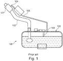
- Fig 1 shows an urea tank system known in the art. Further features and advantages of the present invention will become apparent from the following description of a nonlimiting embodiment of the invention which will be explained below with reference to the drawing, wherein:
- the term "adapter” refers to a “connection piece” or “interconnection piece”. In the context of the present invention this element can also be referred to as a “splitter” or a “combiner”, as will become clear further.
- FIG. 1 shows an urea tank system 100 known in the art. It contains a filler head 101 with an opening for receiving a filler nozzle (not shown in FIG. 1 ). The opening has grooves for allowing gas to escape into the environment.
- the urea entering the filler head 101 flows into an urea tank 103 via filler pipe 102. As urea flows into the urea tank, gas (or air) is pressed out of the tank, and returns to the filler head 101 via return line 105, dip tube 106, and connection 104.
- the filler head 101 thus allows passage of the urea stream towards the tank, and allows passage of gas (or air) from the tank into the environment.
- connection 104 forms an defined angle with the filler head, and/or because two tubes are required (one for air and one for urea) spanning substantially the total distance between the filler head and the tank. Finding two paths between the obstructions formed by enforcements of the vehicle structure is not always easy.
- the filler head 8 has a first end 15 comprising an opening 28 for receiving a filler nozzle 25 (cf. FIG. 6 ) for receiving urea.
- the opening 28 further comprises a plurality of ribs 10 or grooves for centring the filler nozzle, and for allowing gas to escape from the filler head 8 into the environment.
- the filler head 8 further comprises a second end 16 having an inner tubular portion 26 with a first diameter d1 for transporting urea, and having an outer tubular portion 27 with a second diameter d2 larger than the first diameter d1 for transporting gas in the space between the inner tubular portion 26 and the outer tubular portion 27.
- the coaxial tube 7 tube comprises (cf. FIG. 4 ): an inner tube 21 fluidly connectable to the inner tubular portion 26 of the filler head 8 for transporting urea towards the urea tank 1, and an outer tube 22 fluidly connectable to the outer tubular portion 27 of the filler head 8 for transporting gas toward the filler head 8.
- the adapter 6 comprises (cf. FIG. 5 ): a first end 14 comprising an inner tubular portion 23 and an outer tubular portion 24, the inner tubular portion and the outer tubular portion being arranged coaxially; and a second tubular end 13 in fluid connection with the outer tubular portion 24, and connectable to the gas outlet 20 of the urea tank 1; and a third tubular end 12 in fluid connection with the inner tubular portion 23, and connectable to the urea inlet 19 of the urea tank 1.
- connection 104 as present in the prior art system 100 according to FIG. 1 is physically spaced apart from the filler head 8 of the urea tank system 40 according to the present invention, allowing easy mounting of the filler head 8, as it no longer has lateral protrusions or connections.
- the coaxial tube 7 is a flexible tube.
- a coaxial tube By providing a coaxial tube, only a single component needs to be routed, but, when connected between the adapter 6 and the filler head 8, it forms two distinct channels.
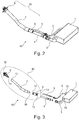
- FIG. 2 is a perspective view
- FIG. 3 is an exploded view of an urea tank system 40 as proposed herein.
- the urea tank system 40 comprises an urea tank 1 having an urea inlet port 19, and a gas outlet port 20, fluidly connected to a filler head 8 via several tubes or conduits in such a manner that urea injected via the filler head 8 flows towards and into the urea tank 1 via a "first channel”, and such that gas (or air) pressed out of the tank 1 flows toward the filler head 8 via a "second channel”, and escapes into the environment.
- the system of FIG. 2 and FIG. 3 comprises a filler head 8 (explained in more detail in FIG. 6 and FIG. 8 ).
- the filler head 8 is fluidly connected to a coaxial tube 7 (explained in more in FIG. 4 ).
- the coaxial tube 7 is fluidly connected to an adapter 6 (explained in more detail in FIG. 5 and FIG. 7 ).
- the adapter 6 has a first tubular end 13 fluidly connected (directly or indirectly) to the gas outlet 20 of the urea tank 1.
- the first tubular end 13 of the adapter 6 is connected to the gas outlet port 20 via a gas discharge tube 2 (also denoted herein as a gas connection tube 2) and via an optional intermediate gas connection tube 5, but of course the latter two tubes may also be combined.
- the adapter 6 further has a third tubular end 12 fluidly connected (directly or indirectly) to the urea inlet 19 of the urea tank 1.
- the third tubular end 12 of the adapter 6 is connected to the urea inlet 19 vian urea connection tube 3 and via an optional intermediate urea connection tube 4, but of course the latter two tubes may also be combined.
- FIG. 4 shows a cross sectional view of an exemplary "coaxial tube” comprised in the assembly of FIG. 3 .
- the coaxial tube 7 comprises an inner tube 21 with a first diameter d1, and an outer tube 22 with a second diameter d2 larger than d1.
- the inner tube 21 defines the urea channel.
- the space between the inner tube 21 and the outer tube 22 (indicated by distance g1), defines the gas channel. While shown in FIG. 4 perfectly coaxially arranged with both of their longitudinal axes coinciding, in practice the inner tube 21 need not be exactly located in the middle of the outer tube 22, and in practice probably will not be located exactly in the middle, especially if the coaxial tube 7 is bent, but the working principle is the same.
- the gas or air flows in a first direction X towards the filler head 8, and the urea flows in a second direction Y towards the urea tank 1.
- FIG. 5 shows a cross sectional view of an exemplary "adapter" comprised in the assembly of FIG. 3 .
- the adapter 6 has a first tubular end 14 comprising an inner tubular portion 23 and an outer tubular portion 24 arranged coaxially.
- the inner tubular portion 23 is to be connected to the inner tube 21 of the coaxial tube 7, and the outer tubular portion 24 of the adapter 6 is to be connected to the outer tube 22 of the coaxial tube 7.
- the adapter 6 further comprises a second tubular end 13 to be connected to the gas connection tube 2 (or intermediate gas connection tube 5).
- the adapter 6 further comprises a third tubular end 12 to be connected to the urea connection tube 3 (or the intermediate urea connection tube 4).
- first tubular end 14 and the third tubular end 12 are collinear, and the second tubular end 13 and the third tubular end 12 define an angle.
- the outer tubular portion 24 of the adapter 6 extends beyond the inner tubular portion 23 of the adapter 6 in its longitudinal direction. While not immediately visible from FIG. 5 , the urea channel and the gas channel are substantially separated from each other during operation, as will be explained further in FIG. 7 .
- FIG. 6 shows a cross sectional view of an exemplary "filler head" comprised in the assembly of FIG. 3 .
- the filler head 8 has a first end 15 comprising an opening 28 sufficiently large for receiving a filler nozzle 25.
- the opening 28 further comprises longitudinal ribs or grooves 10 forming air channels through which gas can escape into the environment.
- the filler head 8 further comprises a second end 16 having an inner tubular portion 26 for transporting the urea, and an outer tubular portion 27 for receiving the gas coming from the urea tank 1.
- the filler head 8 is geometrically shaped such that the returning air or gas flow does not hinder the urea flow (better visible in FIG. 8 ).
- the inner tubular portion 26 of the filler head 8 is tapered or conical for allowing liquid tight connection with the inner tube 21 of the coaxial tube 7.
- FIG. 7 shows a cross sectional view of the "adapter" of FIG. 5 during actual use, and shows the direction of gas flow X, and the direction of urea flow Y. It can be seen that the inner tube 21 of the coaxial tube 7 engages with the inner tubular portion 23 of the adapter 6, and that the outer tube 22 of the coaxial tube 7 engages with the outer tubular portion 24 of the adapter 6, thereby forming two discrete channels.
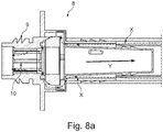
- FIG. 8 shows a cross sectional view of the "filler head" of FIG. 6 during use, and shows the direction of gas or air flow X, and the direction of urea flow Y. It can be seen how the gas flow can escape to the environment via the grooves or ribs 10.
- the filler head 8 has a threaded filler mouth 9 for mounting a bottle, such as e.g. Kruse bottles.
- Fig. 8a is an enlargement view of Fig. 8 in particular to better represent the gas or air flow X.
Landscapes
- Engineering & Computer Science (AREA)
- Chemical & Material Sciences (AREA)
- Mechanical Engineering (AREA)
- Combustion & Propulsion (AREA)
- Chemical Kinetics & Catalysis (AREA)
- Transportation (AREA)
- General Engineering & Computer Science (AREA)
- Sustainable Development (AREA)
- Life Sciences & Earth Sciences (AREA)
- Sustainable Energy (AREA)
- Toxicology (AREA)
- Health & Medical Sciences (AREA)
- Exhaust Gas After Treatment (AREA)
Claims (13)
- Ensemble destiné à être utilisé dans un système de réservoir d'urée, comprenant :- une tête de remplissage (8) possédant une première extrémité (15) comprenant :* une ouverture (28) dotée d'une pluralité de rainures (10) pour recevoir de l'urée en provenance d'une buse de remplissage (25) tout en laissant un gaz s'échapper par les rainures (10) ;* une seconde extrémité (16) possédant une partie tubulaire interne (26) pour transporter l'urée, et une partie tubulaire externe (27) pour recevoir le gaz ;- un tube coaxial (7) comprenant :caractérisé en ce que l'ensemble comprend en outre :* un tube interne (21) pour transporter l'urée ; et* un tube externe (22) pour transporter le gaz ;- un adaptateur (6) comportant :* une première extrémité tubulaire (14) comprenant une partie tubulaire interne (23) et une partie tubulaire externe (24) agencées coaxialement, la partie tubulaire interne (23) étant reliée au tube interne (21) du tube coaxial (7) et la partie tubulaire externe (24) étant reliée au tube externe (22) du tube coaxial (7) ;* une deuxième extrémité tubulaire (13) en liaison fluidique avec la partie tubulaire externe (24) et pouvant être reliée à une évacuation de gaz (20) d'un réservoir d'urée (1) ;* une troisième extrémité tubulaire (12) en liaison fluidique avec la partie tubulaire interne (23) et pouvant être reliée à une admission d'urée (19) du réservoir d'urée (1).
- Ensemble selon la revendication 1, dans lequel la partie tubulaire interne (26) de la tête de remplissage (8) est effilée ou conique.
- Ensemble selon la revendication 1 ou 2, dans lequel le tube coaxial (7) a une longueur d'au moins 30 cm, ou d'au moins 40 cm, ou d'au moins 50 cm, ou d'au moins 60 cm.
- Ensemble selon l'une quelconque des revendications précédentes, dans lequel le tube interne (21) et le tube externe (22) du tube coaxial (7) ont un diamètre constant sur toute leur longueur.
- Ensemble selon l'une quelconque des revendications précédentes, dans lequel un second diamètre (d2) de la partie tubulaire externe (27) de la tête de remplissage (8) est plus grand d'au moins 10 mm qu'un premier diamètre (d1) de la partie tubulaire interne (26) de la tête de remplissage (8).
- Ensemble selon l'une quelconque des revendications précédentes, dans lequel la deuxième extrémité tubulaire (13) et la troisième extrémité tubulaire (12) de l'adaptateur (6) définissent un angle (α) dans la plage.
- Système de réservoir d'urée (1) comprenant :- l'ensemble selon l'une quelconque des revendications précédentes ;- un réservoir d'urée (1) ;- un tube de raccordement gazeux (2) raccordant fluidiquement la deuxième extrémité tubulaire (13) de l'adaptateur (6) et l'évacuation gazeuse (20) du réservoir d'urée (1) ;- un tube de raccordement d'urée (3) raccordant fluidiquement la troisième extrémité tubulaire (12) de l'adaptateur (6) et l'admission gazeuse (19) du réservoir d'urée (1).
- Système de réservoir d'urée (1) selon la revendication 7, comprenant en outre un tube de raccordement gazeux intermédiaire (5) raccordé fluidiquement entre la deuxième extrémité tubulaire (13) de l'adaptateur (6) et le tube de raccordement gazeux (2) .
- Système de réservoir d'urée (1) selon la revendication 7 ou 8, comprenant en outre un tube de raccordement d'urée intermédiaire (4) raccordé fluidiquement entre la deuxième extrémité tubulaire (13) de l'adaptateur (6) et le tube de raccordement gazeux (2) .
- Tête de remplissage (8) destinée à l'ensemble selon l'une quelconque des revendications 1 à 6 ou au système de réservoir d'urée selon l'une quelconque des revendications 7 à 9, comprenant :- une première extrémité (15) comprenant une ouverture (28) destinée à recevoir une buse de remplissage (25) pour recevoir l'urée, l'ouverture (28) comprenant en outre une pluralité d'arêtes (10) ou de rainures pour laisser un gaz s'échapper de la tête de remplissage (8) vers l'environnement ;- une seconde extrémité (16) possédant une partie tubulaire interne (26) ayant un premier diamètre (d1) pour transporter l'urée, et comportant une partie tubulaire externe (27) ayant un second diamètre (d2) plus grand que le premier diamètre (d1) pour transporter le gaz dans l'espace entre la partie tubulaire interne (26) et la partie tubulaire externe (27).
- Tête de remplissage (8) selon la revendication 10, dans laquelle la partie tubulaire interne (26) de la tête de remplissage (8) est effilée ou conique.
- Adaptateur (6) destiné à l'ensemble selon l'une quelconque des revendications 1 à 6 ou au système de réservoir d'urée selon l'une quelconque des revendications 7 à 9, comprenant :- une première extrémité tubulaire (14) comprenant une partie tubulaire interne (23) et une partie tubulaire externe (24), la partie tubulaire interne (23) et la partie tubulaire externe (24) étant agencées coaxialement ;- une deuxième extrémité tubulaire (13) en liaison fluidique avec la partie tubulaire externe (24), et pouvant être reliée à l'évacuation gazeuse (20) du réservoir d'urée (1) ;- une troisième extrémité tubulaire (12) en liaison fluidique avec la partie tubulaire interne (23), et pouvant être reliée à l'admission d'urée (19) du réservoir d'urée (1).
- Adaptateur (6) selon la revendication 12,dans lequel la partie tubulaire externe (24) s'étend au-delà de la partie tubulaire interne (23) ; et/oudans lequel la deuxième extrémité tubulaire (13) et la troisième extrémité tubulaire (12) de l'adaptateur (6) définissent un angle (α) dans la plage de 10° à 30°.
Priority Applications (3)
| Application Number | Priority Date | Filing Date | Title |
|---|---|---|---|
| EP19178315.8A EP3748088B1 (fr) | 2019-06-05 | 2019-06-05 | Ensemble pour un système de réservoir d'urée |
| US16/880,378 US11148522B2 (en) | 2019-06-05 | 2020-05-21 | Assembly for an urea tank system |
| CN202010503111.XA CN112049714A (zh) | 2019-06-05 | 2020-06-05 | 用于尿素罐系统的组件 |
Applications Claiming Priority (1)
| Application Number | Priority Date | Filing Date | Title |
|---|---|---|---|
| EP19178315.8A EP3748088B1 (fr) | 2019-06-05 | 2019-06-05 | Ensemble pour un système de réservoir d'urée |
Publications (2)
| Publication Number | Publication Date |
|---|---|
| EP3748088A1 EP3748088A1 (fr) | 2020-12-09 |
| EP3748088B1 true EP3748088B1 (fr) | 2021-11-03 |
Family
ID=66826819
Family Applications (1)
| Application Number | Title | Priority Date | Filing Date |
|---|---|---|---|
| EP19178315.8A Active EP3748088B1 (fr) | 2019-06-05 | 2019-06-05 | Ensemble pour un système de réservoir d'urée |
Country Status (3)
| Country | Link |
|---|---|
| US (1) | US11148522B2 (fr) |
| EP (1) | EP3748088B1 (fr) |
| CN (1) | CN112049714A (fr) |
Family Cites Families (35)
| Publication number | Priority date | Publication date | Assignee | Title |
|---|---|---|---|---|
| US3187936A (en) * | 1962-11-01 | 1965-06-08 | Gen Motors Corp | Integral fuel filler pipe and vent tube |
| CA1072026A (fr) * | 1976-11-10 | 1980-02-19 | Lee A. Germain | Goulot de remplissage muni d'un dispositif de recuperation des vapeurs |
| US4274549A (en) * | 1979-09-27 | 1981-06-23 | The Goodyear Tire & Rubber Company | Apparatus for fuel vapor recovery |
| DE3540740A1 (de) * | 1985-11-16 | 1987-05-21 | Porsche Ag | Einfuellstutzen fuer einen kraftstoffbehaelter, insbesondere fuer kraftfahrzeuge |
| US4770677A (en) * | 1986-03-31 | 1988-09-13 | Stant Inc. | Vapor recovery system |
| US4836835A (en) * | 1986-03-31 | 1989-06-06 | Stant Inc. | Vacuum-actuated vapor recovery system |
| US5131439A (en) * | 1987-03-26 | 1992-07-21 | Whitehead Engineered Products, Inc. | System for controlling the release of fuel vapors from a vehicle fuel tank |
| SE469552B (sv) * | 1991-12-18 | 1993-07-26 | Volvo Ab | Avluftningsanordning vid braenslepaafyllningsroer |
| US5271438A (en) * | 1992-06-22 | 1993-12-21 | Stant Manufacturing Inc. | Capless vehicle refueling system with moving fill passageway |
| US5497809A (en) * | 1994-01-05 | 1996-03-12 | Wolf; Lawrence W. | Vented bending sleeves for coaxial tubing systems |
| US5740842A (en) * | 1995-02-17 | 1998-04-21 | Walter Alfmeier GmbH + Co. Prazisions-Baugruppenelemente | Venting device for vehicle fuel tanks |
| US5730194A (en) * | 1996-03-21 | 1998-03-24 | Stant Manufacturing Inc. | Capless filler neck closure system |
| US5829619A (en) * | 1997-08-04 | 1998-11-03 | General Motors Corporation | Adapter for motor vehicle fuel filler pipes |
| US6135167A (en) | 1998-07-14 | 2000-10-24 | Kiholm Industries Llc. | Method and apparatus for a filler valve |
| US6152199A (en) * | 1999-08-25 | 2000-11-28 | Nusbaumer; Joseph M. | Safety closure for filling system, remote actuator therefor and methods of making the same |
| JP3632610B2 (ja) * | 2001-03-26 | 2005-03-23 | 日産自動車株式会社 | 自動車の燃料給油口構造 |
| US7198078B2 (en) * | 2003-07-04 | 2007-04-03 | Toyoda Gosei Co., Ltd. | Filler pipe |
| US7694665B2 (en) | 2007-02-05 | 2010-04-13 | Raval A.C.S. Ltd. | Liquid vapor separator |
| US20090188923A1 (en) * | 2007-12-10 | 2009-07-30 | Fuel Systems, Inc. | Urea solution tank assembly |
| DE102009011518A1 (de) | 2009-03-06 | 2010-09-16 | Kautex Textron Gmbh & Co. Kg | Reduktionsmittelbehälter |
| DE202010001147U1 (de) | 2009-12-22 | 2011-05-12 | Reutter Gmbh | Einfüllstutzen für einen Flüssigkeitstank, insbesondere Harnstofftank an Kraftfahrzeugen |
| DE102011009745B4 (de) | 2011-01-28 | 2012-09-13 | Kautex Textron Gmbh & Co. Kg | Einfüllstutzen für einen Nebenflüssigkeitsbehälter |
| EP2665901B1 (fr) | 2011-04-12 | 2014-11-05 | Reutter GmbH | Tubulure de remplissage pour un réservoir de liquide, en particulier un réservoir d'urée, sur des véhicules automobiles |
| DE202011109524U1 (de) | 2011-12-21 | 2013-03-25 | Reutter Gmbh | Füllrohranordnung für einen Flüssigkeitsvorratsbehälter fürKraftfahrzeuge |
| JP5349576B2 (ja) * | 2011-12-27 | 2013-11-20 | 株式会社小松製作所 | 還元剤水溶液ミキシング装置及び排気ガス後処理装置 |
| DE102013100076A1 (de) | 2013-01-07 | 2014-07-10 | Veritas Ag | Befüllkopf |
| DE102013016683A1 (de) | 2013-10-09 | 2015-04-09 | Kautex Textron Gmbh & Co. Kg | Einfülleinrichtung für einen Kraftfahrzeug-Betriebsflüssigkeitsbehälter |
| KR101567229B1 (ko) | 2014-07-07 | 2015-11-09 | 현대자동차주식회사 | 요소수 오버플로우 방지타입 요소수 필러 넥 및 요소수 탱크, 실외형 필러넥을 갖춘 요소수 후처리 시스템 |
| US9701531B2 (en) | 2015-04-10 | 2017-07-11 | Veritas Ag | Filling head for a liquid tank |
| DE102016102737A1 (de) | 2015-09-22 | 2017-03-23 | Dr. Ing. H.C. F. Porsche Aktiengesellschaft | Einfüllstutzen |
| JP6500726B2 (ja) * | 2015-09-28 | 2019-04-17 | 豊田合成株式会社 | 燃料供給装置 |
| JP6702123B2 (ja) * | 2016-09-30 | 2020-05-27 | 豊田合成株式会社 | 給油装置 |
| DE102016220463A1 (de) * | 2016-10-19 | 2018-04-19 | Röchling Automotive SE & Co. KG | Befüllrohranordnung, insbesondere für einen Kfz-SCR-Flüssigkeitstank, mit beweglicher Magnetanordnung |
| JP6522573B2 (ja) * | 2016-11-07 | 2019-05-29 | 豊田合成株式会社 | 燃料供給装置 |
| DE102017108009B3 (de) | 2017-04-13 | 2018-09-13 | Reutter Gmbh | Einfüllstutzen für einen Urea-Vorratsbehälter eines Kraftfahrzeugs |
-
2019
- 2019-06-05 EP EP19178315.8A patent/EP3748088B1/fr active Active
-
2020
- 2020-05-21 US US16/880,378 patent/US11148522B2/en active Active
- 2020-06-05 CN CN202010503111.XA patent/CN112049714A/zh active Pending
Also Published As
| Publication number | Publication date |
|---|---|
| CN112049714A (zh) | 2020-12-08 |
| EP3748088A1 (fr) | 2020-12-09 |
| US20200384850A1 (en) | 2020-12-10 |
| US11148522B2 (en) | 2021-10-19 |
Similar Documents
| Publication | Publication Date | Title |
|---|---|---|
| US9539898B2 (en) | Filler head | |
| US6491069B2 (en) | Integrated vent and fluid transfer fitment | |
| US9849775B2 (en) | Filler neck for an auxiliary liquid reservoir | |
| EP2523818B1 (fr) | Dispositif antisiphon | |
| US7779820B2 (en) | Liquid separator | |
| RU2539615C2 (ru) | Усовершенствованная система заправки емкости для текучей среды транспортного средства | |
| CN105612075B (zh) | 用于机动车工作流体容器的填充装置 | |
| EP3286004B1 (fr) | Réservoirs d'encre | |
| CN101920657B (zh) | 防虹吸设备 | |
| EP2508268A1 (fr) | Système de réservoir de produit chimique rechargeable pour pulvérisateur au pistolet | |
| US9272618B2 (en) | Misfuelling prevention device for a filler neck of a fuel tank | |
| KR20080058331A (ko) | 혼합 이덕터 | |
| US6397902B1 (en) | High speed nozzle with vapor recovery | |
| US5829619A (en) | Adapter for motor vehicle fuel filler pipes | |
| CN105682969B (zh) | 用于机动车工作液容器的填充器颈部 | |
| US6581851B1 (en) | Vapor recovery nozzle | |
| EP3748088A1 (fr) | Ensemble pour un système de réservoir d'urée | |
| KR100517400B1 (ko) | 연료를 탱크에서 차량의 내연 기관으로 운송하기 위한 장치 | |
| US6367520B1 (en) | Fuel filler inlet for motor vehicles | |
| US8215345B2 (en) | Fuel flow shaper | |
| CN111942146A (zh) | 用于排出机动车油箱的气体的排气装置 | |
| US5244018A (en) | Bellowless vapor recovery nozzle | |
| CN106809004A (zh) | 加注器颈部件 | |
| US20260077996A1 (en) | Apparatus for Coupling Pressurized Water Supply to Recreational Vehicle Fresh Water Fill Port | |
| US11938808B2 (en) | Obstruction design |
Legal Events
| Date | Code | Title | Description |
|---|---|---|---|
| PUAI | Public reference made under article 153(3) epc to a published international application that has entered the european phase |
Free format text: ORIGINAL CODE: 0009012 |
|
| STAA | Information on the status of an ep patent application or granted ep patent |
Free format text: STATUS: THE APPLICATION HAS BEEN PUBLISHED |
|
| AK | Designated contracting states |
Kind code of ref document: A1 Designated state(s): AL AT BE BG CH CY CZ DE DK EE ES FI FR GB GR HR HU IE IS IT LI LT LU LV MC MK MT NL NO PL PT RO RS SE SI SK SM TR |
|
| AX | Request for extension of the european patent |
Extension state: BA ME |
|
| STAA | Information on the status of an ep patent application or granted ep patent |
Free format text: STATUS: REQUEST FOR EXAMINATION WAS MADE |
|
| 17P | Request for examination filed |
Effective date: 20210609 |
|
| RBV | Designated contracting states (corrected) |
Designated state(s): AL AT BE BG CH CY CZ DE DK EE ES FI FR GB GR HR HU IE IS IT LI LT LU LV MC MK MT NL NO PL PT RO RS SE SI SK SM TR |
|
| GRAP | Despatch of communication of intention to grant a patent |
Free format text: ORIGINAL CODE: EPIDOSNIGR1 |
|
| STAA | Information on the status of an ep patent application or granted ep patent |
Free format text: STATUS: GRANT OF PATENT IS INTENDED |
|
| INTG | Intention to grant announced |
Effective date: 20210825 |
|
| GRAS | Grant fee paid |
Free format text: ORIGINAL CODE: EPIDOSNIGR3 |
|
| GRAA | (expected) grant |
Free format text: ORIGINAL CODE: 0009210 |
|
| STAA | Information on the status of an ep patent application or granted ep patent |
Free format text: STATUS: THE PATENT HAS BEEN GRANTED |
|
| AK | Designated contracting states |
Kind code of ref document: B1 Designated state(s): AL AT BE BG CH CY CZ DE DK EE ES FI FR GB GR HR HU IE IS IT LI LT LU LV MC MK MT NL NO PL PT RO RS SE SI SK SM TR |
|
| REG | Reference to a national code |
Ref country code: GB Ref legal event code: FG4D |
|
| REG | Reference to a national code |
Ref country code: AT Ref legal event code: REF Ref document number: 1444050 Country of ref document: AT Kind code of ref document: T Effective date: 20211115 Ref country code: CH Ref legal event code: EP |
|
| REG | Reference to a national code |
Ref country code: IE Ref legal event code: FG4D |
|
| REG | Reference to a national code |
Ref country code: DE Ref legal event code: R096 Ref document number: 602019008849 Country of ref document: DE |
|
| REG | Reference to a national code |
Ref country code: LT Ref legal event code: MG9D |
|
| REG | Reference to a national code |
Ref country code: NL Ref legal event code: MP Effective date: 20211103 |
|
| REG | Reference to a national code |
Ref country code: AT Ref legal event code: MK05 Ref document number: 1444050 Country of ref document: AT Kind code of ref document: T Effective date: 20211103 |
|
| PG25 | Lapsed in a contracting state [announced via postgrant information from national office to epo] |
Ref country code: RS Free format text: LAPSE BECAUSE OF FAILURE TO SUBMIT A TRANSLATION OF THE DESCRIPTION OR TO PAY THE FEE WITHIN THE PRESCRIBED TIME-LIMIT Effective date: 20211103 Ref country code: LT Free format text: LAPSE BECAUSE OF FAILURE TO SUBMIT A TRANSLATION OF THE DESCRIPTION OR TO PAY THE FEE WITHIN THE PRESCRIBED TIME-LIMIT Effective date: 20211103 Ref country code: FI Free format text: LAPSE BECAUSE OF FAILURE TO SUBMIT A TRANSLATION OF THE DESCRIPTION OR TO PAY THE FEE WITHIN THE PRESCRIBED TIME-LIMIT Effective date: 20211103 Ref country code: BG Free format text: LAPSE BECAUSE OF FAILURE TO SUBMIT A TRANSLATION OF THE DESCRIPTION OR TO PAY THE FEE WITHIN THE PRESCRIBED TIME-LIMIT Effective date: 20220203 Ref country code: AT Free format text: LAPSE BECAUSE OF FAILURE TO SUBMIT A TRANSLATION OF THE DESCRIPTION OR TO PAY THE FEE WITHIN THE PRESCRIBED TIME-LIMIT Effective date: 20211103 |
|
| PG25 | Lapsed in a contracting state [announced via postgrant information from national office to epo] |
Ref country code: IS Free format text: LAPSE BECAUSE OF FAILURE TO SUBMIT A TRANSLATION OF THE DESCRIPTION OR TO PAY THE FEE WITHIN THE PRESCRIBED TIME-LIMIT Effective date: 20220303 Ref country code: SE Free format text: LAPSE BECAUSE OF FAILURE TO SUBMIT A TRANSLATION OF THE DESCRIPTION OR TO PAY THE FEE WITHIN THE PRESCRIBED TIME-LIMIT Effective date: 20211103 Ref country code: PT Free format text: LAPSE BECAUSE OF FAILURE TO SUBMIT A TRANSLATION OF THE DESCRIPTION OR TO PAY THE FEE WITHIN THE PRESCRIBED TIME-LIMIT Effective date: 20220303 Ref country code: PL Free format text: LAPSE BECAUSE OF FAILURE TO SUBMIT A TRANSLATION OF THE DESCRIPTION OR TO PAY THE FEE WITHIN THE PRESCRIBED TIME-LIMIT Effective date: 20211103 Ref country code: NO Free format text: LAPSE BECAUSE OF FAILURE TO SUBMIT A TRANSLATION OF THE DESCRIPTION OR TO PAY THE FEE WITHIN THE PRESCRIBED TIME-LIMIT Effective date: 20220203 Ref country code: NL Free format text: LAPSE BECAUSE OF FAILURE TO SUBMIT A TRANSLATION OF THE DESCRIPTION OR TO PAY THE FEE WITHIN THE PRESCRIBED TIME-LIMIT Effective date: 20211103 Ref country code: LV Free format text: LAPSE BECAUSE OF FAILURE TO SUBMIT A TRANSLATION OF THE DESCRIPTION OR TO PAY THE FEE WITHIN THE PRESCRIBED TIME-LIMIT Effective date: 20211103 Ref country code: HR Free format text: LAPSE BECAUSE OF FAILURE TO SUBMIT A TRANSLATION OF THE DESCRIPTION OR TO PAY THE FEE WITHIN THE PRESCRIBED TIME-LIMIT Effective date: 20211103 Ref country code: GR Free format text: LAPSE BECAUSE OF FAILURE TO SUBMIT A TRANSLATION OF THE DESCRIPTION OR TO PAY THE FEE WITHIN THE PRESCRIBED TIME-LIMIT Effective date: 20220204 Ref country code: ES Free format text: LAPSE BECAUSE OF FAILURE TO SUBMIT A TRANSLATION OF THE DESCRIPTION OR TO PAY THE FEE WITHIN THE PRESCRIBED TIME-LIMIT Effective date: 20211103 |
|
| PG25 | Lapsed in a contracting state [announced via postgrant information from national office to epo] |
Ref country code: SM Free format text: LAPSE BECAUSE OF FAILURE TO SUBMIT A TRANSLATION OF THE DESCRIPTION OR TO PAY THE FEE WITHIN THE PRESCRIBED TIME-LIMIT Effective date: 20211103 Ref country code: SK Free format text: LAPSE BECAUSE OF FAILURE TO SUBMIT A TRANSLATION OF THE DESCRIPTION OR TO PAY THE FEE WITHIN THE PRESCRIBED TIME-LIMIT Effective date: 20211103 Ref country code: RO Free format text: LAPSE BECAUSE OF FAILURE TO SUBMIT A TRANSLATION OF THE DESCRIPTION OR TO PAY THE FEE WITHIN THE PRESCRIBED TIME-LIMIT Effective date: 20211103 Ref country code: EE Free format text: LAPSE BECAUSE OF FAILURE TO SUBMIT A TRANSLATION OF THE DESCRIPTION OR TO PAY THE FEE WITHIN THE PRESCRIBED TIME-LIMIT Effective date: 20211103 Ref country code: DK Free format text: LAPSE BECAUSE OF FAILURE TO SUBMIT A TRANSLATION OF THE DESCRIPTION OR TO PAY THE FEE WITHIN THE PRESCRIBED TIME-LIMIT Effective date: 20211103 Ref country code: CZ Free format text: LAPSE BECAUSE OF FAILURE TO SUBMIT A TRANSLATION OF THE DESCRIPTION OR TO PAY THE FEE WITHIN THE PRESCRIBED TIME-LIMIT Effective date: 20211103 |
|
| REG | Reference to a national code |
Ref country code: DE Ref legal event code: R097 Ref document number: 602019008849 Country of ref document: DE |
|
| PLBE | No opposition filed within time limit |
Free format text: ORIGINAL CODE: 0009261 |
|
| STAA | Information on the status of an ep patent application or granted ep patent |
Free format text: STATUS: NO OPPOSITION FILED WITHIN TIME LIMIT |
|
| 26N | No opposition filed |
Effective date: 20220804 |
|
| PG25 | Lapsed in a contracting state [announced via postgrant information from national office to epo] |
Ref country code: AL Free format text: LAPSE BECAUSE OF FAILURE TO SUBMIT A TRANSLATION OF THE DESCRIPTION OR TO PAY THE FEE WITHIN THE PRESCRIBED TIME-LIMIT Effective date: 20211103 |
|
| PG25 | Lapsed in a contracting state [announced via postgrant information from national office to epo] |
Ref country code: SI Free format text: LAPSE BECAUSE OF FAILURE TO SUBMIT A TRANSLATION OF THE DESCRIPTION OR TO PAY THE FEE WITHIN THE PRESCRIBED TIME-LIMIT Effective date: 20211103 |
|
| PG25 | Lapsed in a contracting state [announced via postgrant information from national office to epo] |
Ref country code: MC Free format text: LAPSE BECAUSE OF FAILURE TO SUBMIT A TRANSLATION OF THE DESCRIPTION OR TO PAY THE FEE WITHIN THE PRESCRIBED TIME-LIMIT Effective date: 20211103 |
|
| REG | Reference to a national code |
Ref country code: CH Ref legal event code: PL |
|
| REG | Reference to a national code |
Ref country code: BE Ref legal event code: MM Effective date: 20220630 |
|
| PG25 | Lapsed in a contracting state [announced via postgrant information from national office to epo] |
Ref country code: LU Free format text: LAPSE BECAUSE OF NON-PAYMENT OF DUE FEES Effective date: 20220605 Ref country code: LI Free format text: LAPSE BECAUSE OF NON-PAYMENT OF DUE FEES Effective date: 20220630 Ref country code: IE Free format text: LAPSE BECAUSE OF NON-PAYMENT OF DUE FEES Effective date: 20220605 Ref country code: FR Free format text: LAPSE BECAUSE OF NON-PAYMENT OF DUE FEES Effective date: 20220630 Ref country code: CH Free format text: LAPSE BECAUSE OF NON-PAYMENT OF DUE FEES Effective date: 20220630 |
|
| PG25 | Lapsed in a contracting state [announced via postgrant information from national office to epo] |
Ref country code: IT Free format text: LAPSE BECAUSE OF FAILURE TO SUBMIT A TRANSLATION OF THE DESCRIPTION OR TO PAY THE FEE WITHIN THE PRESCRIBED TIME-LIMIT Effective date: 20211103 Ref country code: BE Free format text: LAPSE BECAUSE OF NON-PAYMENT OF DUE FEES Effective date: 20220630 |
|
| P01 | Opt-out of the competence of the unified patent court (upc) registered |
Effective date: 20230620 |
|
| GBPC | Gb: european patent ceased through non-payment of renewal fee |
Effective date: 20230605 |
|
| PG25 | Lapsed in a contracting state [announced via postgrant information from national office to epo] |
Ref country code: MK Free format text: LAPSE BECAUSE OF FAILURE TO SUBMIT A TRANSLATION OF THE DESCRIPTION OR TO PAY THE FEE WITHIN THE PRESCRIBED TIME-LIMIT Effective date: 20211103 Ref country code: CY Free format text: LAPSE BECAUSE OF FAILURE TO SUBMIT A TRANSLATION OF THE DESCRIPTION OR TO PAY THE FEE WITHIN THE PRESCRIBED TIME-LIMIT Effective date: 20211103 Ref country code: GB Free format text: LAPSE BECAUSE OF NON-PAYMENT OF DUE FEES Effective date: 20230605 |
|
| PG25 | Lapsed in a contracting state [announced via postgrant information from national office to epo] |
Ref country code: HU Free format text: LAPSE BECAUSE OF FAILURE TO SUBMIT A TRANSLATION OF THE DESCRIPTION OR TO PAY THE FEE WITHIN THE PRESCRIBED TIME-LIMIT; INVALID AB INITIO Effective date: 20190605 |
|
| PG25 | Lapsed in a contracting state [announced via postgrant information from national office to epo] |
Ref country code: MT Free format text: LAPSE BECAUSE OF FAILURE TO SUBMIT A TRANSLATION OF THE DESCRIPTION OR TO PAY THE FEE WITHIN THE PRESCRIBED TIME-LIMIT Effective date: 20211103 |
|
| PGFP | Annual fee paid to national office [announced via postgrant information from national office to epo] |
Ref country code: DE Payment date: 20250509 Year of fee payment: 7 |
|
| PGFP | Annual fee paid to national office [announced via postgrant information from national office to epo] |
Ref country code: TR Payment date: 20250522 Year of fee payment: 7 |