EP3748137B1 - System zur gleichzeitigen erzeugung von elektrischer energie und kalter wärmeenergie, und entsprechendes verfahren - Google Patents
System zur gleichzeitigen erzeugung von elektrischer energie und kalter wärmeenergie, und entsprechendes verfahren Download PDFInfo
- Publication number
- EP3748137B1 EP3748137B1 EP20178572.2A EP20178572A EP3748137B1 EP 3748137 B1 EP3748137 B1 EP 3748137B1 EP 20178572 A EP20178572 A EP 20178572A EP 3748137 B1 EP3748137 B1 EP 3748137B1
- Authority
- EP
- European Patent Office
- Prior art keywords
- generator
- production
- absorber
- evaporator
- compressor
- Prior art date
- Legal status (The legal status is an assumption and is not a legal conclusion. Google has not performed a legal analysis and makes no representation as to the accuracy of the status listed.)
- Active
Links
Images



Classifications
-
- F—MECHANICAL ENGINEERING; LIGHTING; HEATING; WEAPONS; BLASTING
- F25—REFRIGERATION OR COOLING; COMBINED HEATING AND REFRIGERATION SYSTEMS; HEAT PUMP SYSTEMS; MANUFACTURE OR STORAGE OF ICE; LIQUEFACTION SOLIDIFICATION OF GASES
- F25B—REFRIGERATION MACHINES, PLANTS OR SYSTEMS; COMBINED HEATING AND REFRIGERATION SYSTEMS; HEAT PUMP SYSTEMS
- F25B25/00—Machines, plants or systems, using a combination of modes of operation covered by two or more of the groups F25B1/00 - F25B23/00
- F25B25/02—Compression-sorption machines, plants, or systems
-
- F—MECHANICAL ENGINEERING; LIGHTING; HEATING; WEAPONS; BLASTING
- F01—MACHINES OR ENGINES IN GENERAL; ENGINE PLANTS IN GENERAL; STEAM ENGINES
- F01K—STEAM ENGINE PLANTS; STEAM ACCUMULATORS; ENGINE PLANTS NOT OTHERWISE PROVIDED FOR; ENGINES USING SPECIAL WORKING FLUIDS OR CYCLES
- F01K13/00—General layout or general methods of operation of complete plants
- F01K13/02—Controlling, e.g. stopping or starting
-
- F—MECHANICAL ENGINEERING; LIGHTING; HEATING; WEAPONS; BLASTING
- F01—MACHINES OR ENGINES IN GENERAL; ENGINE PLANTS IN GENERAL; STEAM ENGINES
- F01K—STEAM ENGINE PLANTS; STEAM ACCUMULATORS; ENGINE PLANTS NOT OTHERWISE PROVIDED FOR; ENGINES USING SPECIAL WORKING FLUIDS OR CYCLES
- F01K25/00—Plants or engines characterised by use of special working fluids, not otherwise provided for; Plants operating in closed cycles and not otherwise provided for
- F01K25/06—Plants or engines characterised by use of special working fluids, not otherwise provided for; Plants operating in closed cycles and not otherwise provided for using mixtures of different fluids
- F01K25/065—Plants or engines characterised by use of special working fluids, not otherwise provided for; Plants operating in closed cycles and not otherwise provided for using mixtures of different fluids with an absorption fluid remaining at least partly in the liquid state, e.g. water for ammonia
-
- F—MECHANICAL ENGINEERING; LIGHTING; HEATING; WEAPONS; BLASTING
- F01—MACHINES OR ENGINES IN GENERAL; ENGINE PLANTS IN GENERAL; STEAM ENGINES
- F01K—STEAM ENGINE PLANTS; STEAM ACCUMULATORS; ENGINE PLANTS NOT OTHERWISE PROVIDED FOR; ENGINES USING SPECIAL WORKING FLUIDS OR CYCLES
- F01K7/00—Steam engine plants characterised by the use of specific types of engine; Plants or engines characterised by their use of special steam systems, cycles or processes; Control means specially adapted for such systems, cycles or processes; Use of withdrawn or exhaust steam for feed-water heating
-
- F—MECHANICAL ENGINEERING; LIGHTING; HEATING; WEAPONS; BLASTING
- F25—REFRIGERATION OR COOLING; COMBINED HEATING AND REFRIGERATION SYSTEMS; HEAT PUMP SYSTEMS; MANUFACTURE OR STORAGE OF ICE; LIQUEFACTION SOLIDIFICATION OF GASES
- F25B—REFRIGERATION MACHINES, PLANTS OR SYSTEMS; COMBINED HEATING AND REFRIGERATION SYSTEMS; HEAT PUMP SYSTEMS
- F25B1/00—Compression machines, plants or systems with non-reversible cycle
-
- F—MECHANICAL ENGINEERING; LIGHTING; HEATING; WEAPONS; BLASTING
- F25—REFRIGERATION OR COOLING; COMBINED HEATING AND REFRIGERATION SYSTEMS; HEAT PUMP SYSTEMS; MANUFACTURE OR STORAGE OF ICE; LIQUEFACTION SOLIDIFICATION OF GASES
- F25B—REFRIGERATION MACHINES, PLANTS OR SYSTEMS; COMBINED HEATING AND REFRIGERATION SYSTEMS; HEAT PUMP SYSTEMS
- F25B15/00—Sorption machines, plants or systems, operating continuously, e.g. absorption type
-
- F—MECHANICAL ENGINEERING; LIGHTING; HEATING; WEAPONS; BLASTING
- F25—REFRIGERATION OR COOLING; COMBINED HEATING AND REFRIGERATION SYSTEMS; HEAT PUMP SYSTEMS; MANUFACTURE OR STORAGE OF ICE; LIQUEFACTION SOLIDIFICATION OF GASES
- F25B—REFRIGERATION MACHINES, PLANTS OR SYSTEMS; COMBINED HEATING AND REFRIGERATION SYSTEMS; HEAT PUMP SYSTEMS
- F25B2313/00—Compression machines, plants or systems with reversible cycle not otherwise provided for
- F25B2313/027—Compression machines, plants or systems with reversible cycle not otherwise provided for characterised by the reversing means
- F25B2313/0271—Compression machines, plants or systems with reversible cycle not otherwise provided for characterised by the reversing means the compressor allows rotation in reverse direction
-
- F—MECHANICAL ENGINEERING; LIGHTING; HEATING; WEAPONS; BLASTING
- F25—REFRIGERATION OR COOLING; COMBINED HEATING AND REFRIGERATION SYSTEMS; HEAT PUMP SYSTEMS; MANUFACTURE OR STORAGE OF ICE; LIQUEFACTION SOLIDIFICATION OF GASES
- F25B—REFRIGERATION MACHINES, PLANTS OR SYSTEMS; COMBINED HEATING AND REFRIGERATION SYSTEMS; HEAT PUMP SYSTEMS
- F25B2400/00—General features or devices for refrigeration machines, plants or systems, combined heating and refrigeration systems or heat-pump systems, i.e. not limited to a particular subgroup of F25B
- F25B2400/04—Refrigeration circuit bypassing means
- F25B2400/0401—Refrigeration circuit bypassing means for the compressor
-
- F—MECHANICAL ENGINEERING; LIGHTING; HEATING; WEAPONS; BLASTING
- F25—REFRIGERATION OR COOLING; COMBINED HEATING AND REFRIGERATION SYSTEMS; HEAT PUMP SYSTEMS; MANUFACTURE OR STORAGE OF ICE; LIQUEFACTION SOLIDIFICATION OF GASES
- F25B—REFRIGERATION MACHINES, PLANTS OR SYSTEMS; COMBINED HEATING AND REFRIGERATION SYSTEMS; HEAT PUMP SYSTEMS
- F25B2400/00—General features or devices for refrigeration machines, plants or systems, combined heating and refrigeration systems or heat-pump systems, i.e. not limited to a particular subgroup of F25B
- F25B2400/07—Details of compressors or related parts
- F25B2400/075—Details of compressors or related parts with parallel compressors
-
- F—MECHANICAL ENGINEERING; LIGHTING; HEATING; WEAPONS; BLASTING
- F25—REFRIGERATION OR COOLING; COMBINED HEATING AND REFRIGERATION SYSTEMS; HEAT PUMP SYSTEMS; MANUFACTURE OR STORAGE OF ICE; LIQUEFACTION SOLIDIFICATION OF GASES
- F25B—REFRIGERATION MACHINES, PLANTS OR SYSTEMS; COMBINED HEATING AND REFRIGERATION SYSTEMS; HEAT PUMP SYSTEMS
- F25B2400/00—General features or devices for refrigeration machines, plants or systems, combined heating and refrigeration systems or heat-pump systems, i.e. not limited to a particular subgroup of F25B
- F25B2400/14—Power generation using energy from the expansion of the refrigerant
- F25B2400/141—Power generation using energy from the expansion of the refrigerant the extracted power is not recycled back in the refrigerant circuit
-
- Y—GENERAL TAGGING OF NEW TECHNOLOGICAL DEVELOPMENTS; GENERAL TAGGING OF CROSS-SECTIONAL TECHNOLOGIES SPANNING OVER SEVERAL SECTIONS OF THE IPC; TECHNICAL SUBJECTS COVERED BY FORMER USPC CROSS-REFERENCE ART COLLECTIONS [XRACs] AND DIGESTS
- Y02—TECHNOLOGIES OR APPLICATIONS FOR MITIGATION OR ADAPTATION AGAINST CLIMATE CHANGE
- Y02A—TECHNOLOGIES FOR ADAPTATION TO CLIMATE CHANGE
- Y02A30/00—Adapting or protecting infrastructure or their operation
- Y02A30/27—Relating to heating, ventilation or air conditioning [HVAC] technologies
-
- Y—GENERAL TAGGING OF NEW TECHNOLOGICAL DEVELOPMENTS; GENERAL TAGGING OF CROSS-SECTIONAL TECHNOLOGIES SPANNING OVER SEVERAL SECTIONS OF THE IPC; TECHNICAL SUBJECTS COVERED BY FORMER USPC CROSS-REFERENCE ART COLLECTIONS [XRACs] AND DIGESTS
- Y02—TECHNOLOGIES OR APPLICATIONS FOR MITIGATION OR ADAPTATION AGAINST CLIMATE CHANGE
- Y02B—CLIMATE CHANGE MITIGATION TECHNOLOGIES RELATED TO BUILDINGS, e.g. HOUSING, HOUSE APPLIANCES OR RELATED END-USER APPLICATIONS
- Y02B30/00—Energy efficient heating, ventilation or air conditioning [HVAC]
- Y02B30/62—Absorption based systems
-
- Y—GENERAL TAGGING OF NEW TECHNOLOGICAL DEVELOPMENTS; GENERAL TAGGING OF CROSS-SECTIONAL TECHNOLOGIES SPANNING OVER SEVERAL SECTIONS OF THE IPC; TECHNICAL SUBJECTS COVERED BY FORMER USPC CROSS-REFERENCE ART COLLECTIONS [XRACs] AND DIGESTS
- Y02—TECHNOLOGIES OR APPLICATIONS FOR MITIGATION OR ADAPTATION AGAINST CLIMATE CHANGE
- Y02E—REDUCTION OF GREENHOUSE GAS [GHG] EMISSIONS, RELATED TO ENERGY GENERATION, TRANSMISSION OR DISTRIBUTION
- Y02E20/00—Combustion technologies with mitigation potential
- Y02E20/14—Combined heat and power generation [CHP]
Definitions
- the invention relates to the field of thermodynamic systems, and associated methods, for the co-production of electrical energy and thermal energy. Its application is particularly advantageous in the field of stationary systems using low-temperature heat sources such as thermal discharges from industrial processes, solar thermal, biomass, geothermal energy and gas turbines.
- the invention can also find applications in the field of vehicles, whether they are vehicles with a thermal engine or with a hybrid engine requiring thermal energy and electricity.
- the device described in this publication does not make it possible to vary the conditions of electricity and cold production. Cold production and electricity production are always simultaneous.
- the document DE 102006060836 describes a fan wheel for a compressor of an exhaust gas turbocharger or a turbine in secondary air boosters.
- An object of the present invention is therefore to propose a system for co-producing electrical energy and thermal energy which is flexible depending on the needs for electricity and cold, the availability and the cost of energy sources.
- the present invention ensures flexibility in the production of cold and electricity depending on needs and sources.
- the use of a reversible compressor in combination with the refrigerant circulation management module makes the system compact, limiting the number of components and allowing reduced cost and possible integration into non-stationary applications.
- the use of a reversible compressor of the turbomachine type in an absorption cycle is an unusual approach for those skilled in the art for whom problems related to the refrigerant fluid in the compressor in expander mode would arise.
- the compressor is thus adapted to operate alternately as an expander connected to a generator for the production of electricity and as a compressor driven by a motor to compress a fluid.
- the reversible compressor is arranged between the generator and the absorber in bypass of the condenser and the evaporator, that is to say that the fluidic circuit comprises a branch line arranged between the generator and the absorber and in parallel with the condenser and the evaporator and on which the reversible compressor is arranged.
- This bypass arrangement of the reversible compressor allows, through the module for managing the circulation of the working solution in the fluidic circuit, to produce electricity and thermal energy in numerous possible combinations ranging from 100% d electricity or 100% cold thermal energy to a more or less significant proportion of electricity and cold thermal energy, which can advantageously be very low temperature.
- the use of a reversible compressor of the turbomachine type advantageously allows medium and high power electrical production, advantageously greater than 100KWe (electric KiloWatt).
- the reversible compressor is arranged between the evaporator and the absorber, to allow in particular the production of very low temperature cold.
- the thermal energy produced in the first mode of operation is cold, which is produced by the circulation of the working solution in the fluidic circuit, according to the alternative, successively through the generator, the condenser, the evaporator, from the absorber then back into the generator.
- the cold thermal energy produced is very low temperature cold by the circulation of the working solution in the fluidic circuit successively through the generator, the condenser, the evaporator, from the reversible compressor in compressor mode, from the absorber then back into the generator.
- the invention relates to the use of a system for producing thermal energy and electrical energy as described above for electrical production with a power greater than 100 kWe.
- the fluidic circuit comprises a first connection line arranged to ensure the fluidic connection between the evaporator and the reversible compressor and a second connection line to ensure the fluidic connection between the reversible compressor and the absorber.
- the working solution comprises ammonia (NH 3 ) as refrigerant fluid and water (H 2 O) as absorbent.
- NH 3 ammonia
- H 2 O water
- the working solution is not an organic fluid.
- the system comprises at least one cold storage module associated with the evaporator.
- the refrigeration storage module is associated with the absorber to remove refrigeration from storage.
- the system comprises at least one calorie storage module associated with the absorber.
- the calorie storage module is associated with the generator to release the calories.
- the system comprises at least one electricity storage module associated with the compressor, more specifically with the generator.
- the thermal energy produced is very low temperature cold by the circulation of the working solution in the fluidic circuit successively through the generator, the condenser, the evaporator, the reversible compressor in compressor mode, from the absorber then back into the generator.
- the temperature of the cold thermal energy, or low temperature cold, produced is between -10°C and -25°C or -10°C and 20°C.
- the method comprises a heat source comprising low temperature heat advantageously between 70°C and 150°C.
- the upstream and downstream at a given point are taken with reference to the direction of circulation of the fluid in the circuit.
- direct exchange or direct coupling we mean that the exchange of thermal energy takes place directly without an intermediate circuit or component.
- the direct exchange in the condenser or evaporator takes place directly between the refrigerant and for example an air flow.
- the electrical energy and thermal energy production system includes an absorption device.
- An absorption device is a reversible heat pump with thermal “compression” using refrigerant/sorbent couples with strong affinities in order to replace the vapor compression of traditional machines.
- This solution has low electrical consumption, the main energy coming from the thermal source, making it possible to limit the operating cost in the case of the valorization of a low-cost energy source such as gas for example or free (such as solar energy or heat rejection for example).
- An absorption device is therefore composed of 4 main exchangers (generator 1, absorber 4, condenser 2 and evaporator 3), and advantageously from one to three secondary exchangers.
- the role of the three secondary exchangers is to improve the performance of the machine such as: a rectifier 13, an economizer 8, a subcooler 6.
- the absorption device comprises at least one expansion valve 12, and at least one solution loop 11 comprising a solution pump 9 and an expansion valve 10.
- This type of device operates according to three temperature levels: a low temperature level corresponding to the production of cold at the evaporator 3, a level intermediate temperature corresponding to the condensation temperature of the refrigerant, but also to that of absorption of the refrigerant by the absorbent and a high temperature level corresponding to the driving temperature of the generator 1.
- the absorption machine comprises an absorption fluid circuit 100 configured to ensure the fluid connection of the different components of the absorption machine.
- the absorption fluidic circuit 100 is a closed circuit intended to receive the working solution.
- An absorption device operates partly at high pressure between pump 9 upstream of generator 1 and regulator 12, downstream of condenser 102, and partly at low pressure between regulator 12, downstream of condenser 102 and partly at low pressure. pump 9 upstream of generator 101.
- thermodynamic cycle is feasible due to the vapor pressure difference between the absorbent and the refrigerant which is variable depending on the temperature and pressure. This variability allows for a difference in concentration between the poor solution and the rich solution described below.
- the advantage of this absorption cycle is that mechanical compression is replaced by thermochemical compression which uses heat, that is to say a degraded primary energy source. The only primary energy input required is at the solution pump, but its work is approximately 96 times less than the work the steam compressor must provide for similar operating conditions.
- the plant comprises a refrigerant/absorbent working solution comprising, according to one possibility, the Ammonia/Water couple (NH3/H2O).
- the concentrations of the working fluid and the absorbent in the working solution are adapted to the pressure and temperature of the air treatment and lower than the crystallization concentration of the solution.
- the working solution comprises ionic liquids.
- This NH3/H2O couple can be used for air conditioning applications, but also refrigeration and there is no crystallization possible over the pressure and temperature operating ranges.
- the vapor pressure difference between the absorbent and the refrigerant is weak. There are therefore traces of water carried with the ammonia vapor at the outlet of generator 1, sometimes requiring the presence of a rectifier 13.
- the working solution is called rich, because the concentration of refrigerant is greater than in the so-called lean working solution.
- the absorption device comprises a rectifier 13 disposed between the generator 1 and the condenser 2, more precisely on the fluid connection 104.
- the rectifier 13 makes it possible to remove by condensation the traces of water carried with the device fluid.
- the rectifier 13 comprises a cold source 19.
- the cold source 19 is the so-called "rich" working solution at the outlet of the pump 9 of the solution loop 11.
- the system comprises an expander 12 arranged between the condenser 2 and the evaporator 3.
- the expander 12 is configured to expand the refrigerant to the liquid state coming from the condenser 2.
- the expander 12 brings the refrigerant to its evaporation pressure .
- the absorption device can comprise a sub-cooler 6 arranged between the condenser 2 and the evaporator 3, and between the evaporator 3 and the absorber 4, more precisely on the fluid connection 105 and on a fluid connection 107 in outlet of the evaporator.
- the subcooler 6 makes it possible to subcool the refrigerant at the inlet of the evaporator 3 and to preheat the refrigerant to the vapor state at the outlet of the evaporator 3.
- This exchanger therefore makes it possible to reduce the size of the condenser 2 and the evaporator 3 and thus significantly improve the performance of the machine.
- the relevance of this component depends on the operating temperatures, the size of the machine and the cost of the exchangers.
- the system according to the invention comprises a module for managing the circulation of the working solution.
- the management module is configured to define the operating conditions of the system based on energy needs and source fluctuations. Particularly when thermal energy is desired: cold, low temperature cold, or electrical energy, or a mix of thermal energy: cold and electrical energy, depending on the temperatures of the sources, the price of electricity, etc.
- the management module comprises in particular adjustment valves and/or at least one expansion valve advantageously whose opening is adjustable and/or means for adjusting the circulation flow rates of the working solution and the refrigerant in particular by controlling of the speed of the pump 9.
- the system and the management module according to the invention have the advantage of being compact by advantageously requiring only a few additional components such as valves, possibly temperature and pressure sensors, this which reduces costs and space requirements allowing the integration of the system according to the invention into the mobile application framework.
- the system is configured to operate in at least two operating modes.
- the system In the first mode of operation, the system produces either cold thermal energy or electrical energy.
- a first condition is the request for cold production by the absorption machine
- the request for cold production can be verified by the management module according to a binary command, i.e. cold production value not zero meaning a demand for cold production and a zero cold production value meaning no demand for cold production.
- the working solution circulation management module will define a circulation of the working solution following a classic absorption cycle as illustrated in figure 2 .
- This function is called function A.
- the production of cold is done in particular from a low temperature heat source such as the waste heat, for example between 70°C and 150°C, which can fluctuate. , such as a solar source or waste heat linked to the start-up of a heat engine or intermittent industrial discharges.
- a fluctuating heat source advantageously, storage of calories upstream of the production system can be provided.
- the refrigerant of the working solution leaves the generator 1 via the fluid connection 104 advantageously passes through a rectifier 13 before arriving in the condenser 2.
- the refrigerant leaves the condenser 2 via the fluid connection 105 to advantageously pass through the subcooler 6, and advantageously a regulator 12, before arriving via the fluid connection 106 in the evaporator 3.
- the refrigerant leaves the evaporator 3 via the fluid connection 107 to advantageously cross the sub-cooler 6 before arriving in the evaporator 3. absorber 4 by the fluidic connection 115.
- the refrigerant is absorbed by the absorbent and the so-called rich working solution comes out of the absorber by the fluidic connection 108 to circulate in the solution loop 11 comprising the economizer 8, the pump 9 and the regulator 10.
- the solution loop 11 is described below: the so-called rich working solution advantageously passes successively through a pump 9 and an economizer 8 before arriving in the generator 1 via the fluid connection 100.
- the production of cold is done at the level of the evaporator 3 during the evaporation of the refrigerant which is accompanied by cooling of the hot source 17.
- the cooled hot source 17 can then be used for example for air conditioning.
- the module of management of the circulation of the working solution will define a circulation of the working solution following an absorption cycle assisted by a compressor 5 as illustrated in figure 5 .
- This function is called function D.
- the absorption cycle illustrated in figure 5 operates with an additional level of pressure compared to a classic absorption cycle illustrated in figure 2 , between the reversible compressor 5 and the absorber 4.
- the refrigerant of the working solution leaves the generator 1 via the fluid connection 104 advantageously passes through a rectifier 13 before arriving in the condenser 2.
- the refrigerant leaves the condenser 2 via the fluid connection 105 to advantageously pass through the subcooler 6 and a regulator 12 before arriving via the fluid connection 106 in the evaporator 3.
- the refrigerant leaves the evaporator 3 via the fluid connection 107 to advantageously cross the sub-cooler 6.
- the refrigerant leaves the sub-cooler 6 by a fluid connection 111 to arrive in the reversible compressor 5 which is in compressor mode connected to a motor providing work Wc ensuring the compression of the refrigerant.
- the compressed refrigerant emerges from the reversible compressor 5 via a fluid connection 112 opening into the absorber 4.
- the refrigerant is absorbed by the absorbent and the so-called rich working solution emerges from the absorber 4 to pass through the solution loop 11 as described with reference to the figure 2 before returning to generator level 1.
- Compressor 5 thus increases the pressure differential between the low pressure part of the cycle and the high pressure part of the cycle.
- the cold production is thus greater at the level of the evaporator 3.
- the cooled hot source 17 can be used for example for refrigeration.
- a second condition is the demand for electricity production by the system
- the demand for electricity production can be checked by the management module based on a binary command i.e. electricity production value non-zero meaning a demand for electricity production and a zero electricity production value meaning an absence of demand for electricity production.
- the management module of the circulation of the working solution will define a circulation of the working solution as illustrated in Figure 3 .
- the circulation cycle of working solution is similar to a Rankine cycle, more specifically to a Kalina cycle.
- function B The refrigerant of the working solution leaves the generator 1 via the fluid connection 109 and advantageously passes through a superheater 7 before arriving in the reversible compressor 5.
- the refrigerant leaves the reversible compressor 5 via the fluid connection 110 opening into the absorber 4.
- the refrigerant is absorbed by the absorbent and the so-called rich working solution springs from the absorber 4 to pass through the solution loop 11 as described with reference to the figure 2 before returning to generator level 1. Electricity is produced by the reversible compressor in expander mode connected to an electric generator.
- the system produces cold thermal energy and electrical energy simultaneously.
- the thermal energy produced is cold.
- the management module of the circulation of the working solution will define a circulation of the working solution following an absorption cycle and an electricity production cycle as illustrated in Figure 4 .
- This function is called function C.
- the system according to the invention is configured to ensure operation in parallel with the production of electricity and the production of cold, which makes it possible to modulate according to needs the proportion of electricity produced and of cold product.
- the refrigerant of the working solution is directed partially towards a cold production cycle and partially towards an electricity production cycle.
- the reversible compressor 5 is arranged between the generator 1 and the absorber 4 in parallel with the condenser 2 and the evaporator 3. Part of the refrigerant leaving the generator is diverted towards the reversible compressor 5 while the other part circulates towards the condenser 2.
- the refrigerant passing through the fluid connection 104 advantageously passes through a rectifier 13 before arriving in the condenser 2.
- the refrigerant leaves the condenser 2 via the fluid connection 105 to advantageously pass through the sub-cooler 6 and advantageously an expander 12 before arrive via the fluid connection 106 in the evaporator 3.
- the refrigerant leaves the evaporator via the fluid connection 107 to advantageously cross the subcooler 6 before arriving in the absorber 4 via the fluid connection 115.
- the fluid refrigerant is absorbed by the absorbent and the so-called rich working solution comes out of the absorber via the fluid connection 108 to circulate in the solution loop 11 comprising the economizer 8, the pump 9 and the regulator 10.
- the solution loop 11 is described below, the so-called rich working solution advantageously successively passing through a pump 9 and an economizer 8 before arriving in the generator 1 via the fluid connection 100.
- the so-called poor working solution comes out of the generator 1 via the connection fluidic 101 to advantageously successively pass through the economizer 8 and an expander 10 before arriving in the absorber 4.
- the refrigerant passing through the fluid connection 109 advantageously passes through a superheater 7 before arriving at the reversible compressor 5 operating in compressor mode.
- the refrigerant emerges from the compressor 5 compressed by the fluid connection 110 opening into the absorber 4.
- the refrigerant coming from the compressor 5 and the refrigerant coming from the evaporator 3 are brought together to pass through the solution loop 11.
- the refrigerant is absorbed by the absorbent and the so-called rich working solution comes out of the absorber via the fluid connection 108 to circulate in the solution loop 11 comprising the economizer 8, the pump 9 and the regulator 10 as described above.
- the refrigerant is directed at the outlet of the generator 1 towards the rectifier 13 before being divided into two flows respectively towards the condenser 2 by a portion of the fluid connection 104 and towards the reversible compressor 5, advantageously in passing previously by the superheater 7, by a portion of the fluid connection 109.
- the production of cold takes place at the level of the evaporator 3 during the evaporation of the refrigerant which is accompanied by cooling of the hot source 17.
- the cooled hot source 17 can then be used for example for air conditioning. Electricity is produced by the reversible compressor 5 in expander mode connected to an electric generator.
- the system comprises at least one cold storage module associated with the evaporator 3.
- the cold storage thus allows energy storage when the source and the need are not concomitant. Stored refrigeration can be released in the form of cold or in the form of electricity depending on needs.
- the cold storage module can be a thermal storage system using Phase Change Material or directly a cold fluid storage.
- the refrigeration storage module is associated with the evaporator 3 to store refrigerations during operation for cold production.
- the cold storage module is also associated with the absorber 4 to release frigories to the absorber 4 when a cooling source 15 is desired, that is to say in particular in the different operating modes.
- the system comprises at least one electricity storage module associated with the reversible compressor 5 and more specifically with the electric generator associated with the reversible compressor 5.
- the storage of electricity thus allows energy storage when the source and the need are not concomitant.
- the stored electricity can be released in the form of cold or in the form of electricity depending on needs. For example, electric batteries are provided.
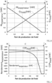
- Q hot being the power Qg delivered by the thermal source, in particular by the heat source 14 at the level of the generator 1, in the form of heat and Wpump the electrical power consumed by the pump 9.
- W compressor being the electrical power Wc consumed by the compressor.
Landscapes
- Engineering & Computer Science (AREA)
- Mechanical Engineering (AREA)
- General Engineering & Computer Science (AREA)
- Physics & Mathematics (AREA)
- Thermal Sciences (AREA)
- Chemical & Material Sciences (AREA)
- Combustion & Propulsion (AREA)
- Sorption Type Refrigeration Machines (AREA)
Claims (9)
- System zum Erzeugen von thermischer und elektrischer Energie, das eine Absorptionsvorrichtung umfasst, die einen Absorber (4), einen Generator (1), einen Kondensator (2), einen Verdampfer (3) und einen Absorptionsfluidkreislauf (100) umfasst, der dazu ausgelegt ist, eine Arbeitslösung aufzunehmen, die ein Kühlmittel und ein Absorptionsmittel umfasst, wobei der Fluidkreislauf (100) den Generator (1) mit dem Kondensator (2), den Kondensator (2) mit dem Verdampfer (3), den Verdampfer (3) mit dem Absorber (4) und den Absorber (4) mit dem Generator (1) verbindet,
dadurch gekennzeichnet, dass das System außerdem Folgendes umfasst:- einen reversiblen Kompressor (5), der im Fluidkreislauf (100) zwischen dem Generator (1) und dem Absorber (4) unter Umgehung des Kondensators (2) und des Verdampfers (3) angeordnet ist, wobei der Fluidkreislauf außerdem eine erste Fluidverbindung (111), die angeordnet ist, um die Fluidverbindung zwischen dem Verdampfer (3) und dem reversiblen Kompressor (5) sicherzustellen, und eine zweite Fluidverbindung (110, 112) umfasst, um die Fluidverbindung zwischen dem reversiblen Kompressor (5) und dem Absorber (4) sicherzustellen, wobei der reversible Kompressor (5) dazu konfiguriert ist, während des Betriebs des Systems abwechselnd im von einem Motor betriebenen Kompressormodus oder im Expansionsmodus, der einen Stromerzeuger betreibt, der dazu konfiguriert ist, Strom zu erzeugen, zu arbeiten, wobei der reversible Kompressor (5) eine Turbomaschine ist,- ein Steuermodul für die Zirkulation der Arbeitslösung im Fluidkreislauf in einem ersten Betriebsmodus, um eine Erzeugung von elektrischer Energie abwechselnd mit einer Erzeugung von Kälte oder Wärme sicherzustellen, und in einem zweiten Betriebsmodus, um die Erzeugung von elektrischer Energie gleichzeitig bei der Erzeugung von Kälte sicherzustellen. - System nach dem vorhergehenden Anspruch, wobei die Arbeitslösung Ammoniak (NH3) als Kühlfluid und Wasser (H2O) als Absorptionsmittel umfasst.
- System nach einem der vorhergehenden Ansprüche, das mindestens ein Kältespeichermodul umfasst, das mit dem Verdampfer (3) verbunden ist.
- System nach einem der vorhergehenden Ansprüche, das mindestens ein Kalorienspeichermodul umfasst, das mit dem Absorber (4) verbunden ist.
- System nach einem der vorhergehenden Ansprüche, das mindestens ein Stromspeichermodul umfasst, das mit dem reversiblen Kompressor (5) verbunden ist.
- Verfahren zum Erzeugen von elektrischer Energie und thermischer Energie durch ein System nach einem der vorhergehenden Ansprüche,
dadurch gekennzeichnet, dass es Folgendes umfasst- im ersten Betriebsmodus abwechselnd:∘ eine Erzeugung von kalter thermischer Energie durch die Zirkulation der Arbeitslösung im Fluidkreislauf (100) nacheinander durch den Generator (1), den Kondensator (2), den Verdampfer (3), den Absorber (4) und dann wieder durch den Generator (1), oder eine Erzeugung von kalter thermischer Energie mit einer sehr niedrigen Temperatur durch eine Zirkulation der Arbeitslösung im Fluidkreislauf nacheinander durch den Generator (1), den Kondensator (2), den Verdampfer (3), den im Kompressormodus arbeitenden reversiblen Kompressor (5), den Absorber (4) und dann wieder durch den Generator (1), oder∘ eine Erzeugung von elektrischer Energie, die durch eine Zirkulation der Arbeitslösung im Fluidkreislauf (100) nacheinander durch den Generator (1), den reversiblen Kompressor (5) im Expansionsmodus, der mit einem Stromerzeuger verbunden ist, den Absorber (4) und dann wieder durch den Generator (1) erfolgt, oder- im zweiten Betriebsmodus gleichzeitig:∘ die Erzeugung von kalter thermischer Energie, die durch die Zirkulation der Arbeitslösung im Fluidkreislauf (100) nacheinander durch den Generator (1), den Kondensator (2), den Verdampfer (3), den Absorber (4) und dann wieder durch den Generator (1) erfolgt, und∘ die Erzeugung von elektrischer Energie, die durch die Zirkulation der Arbeitslösung im Fluidkreislauf (100) nacheinander durch den Generator (1), den reversiblen Kompressor (5) im Expansionsmodus, der mit einem Stromerzeuger verbunden ist, den Absorber (4) und dann wieder durch den Generator (1) erfolgt. - Verfahren nach dem vorhergehenden Anspruch, wobei die Temperatur der erzeugten kalten thermischen Energie zwischen -10°C und -25°C oder -10°C und 20°C liegt.
- Verfahren nach einem der Ansprüche 6 bis 7, das eine Wärmequelle mit Niedertemperaturwärme, vorteilhafterweise zwischen 70°C und 150°C, umfasst.
- Verwendung eines Systems zum Erzeugen von thermischer und elektrischer Energie nach einem der Ansprüche 1 bis 5 zur Stromerzeugung mit einer Leistung von mehr als 100 kWe.
Applications Claiming Priority (1)
| Application Number | Priority Date | Filing Date | Title |
|---|---|---|---|
| FR1905984A FR3097038B1 (fr) | 2019-06-06 | 2019-06-06 | Système de co-production d’énergie électrique et d’énergie thermique froide et procédé associé |
Publications (2)
| Publication Number | Publication Date |
|---|---|
| EP3748137A1 EP3748137A1 (de) | 2020-12-09 |
| EP3748137B1 true EP3748137B1 (de) | 2024-07-31 |
Family
ID=67957087
Family Applications (1)
| Application Number | Title | Priority Date | Filing Date |
|---|---|---|---|
| EP20178572.2A Active EP3748137B1 (de) | 2019-06-06 | 2020-06-05 | System zur gleichzeitigen erzeugung von elektrischer energie und kalter wärmeenergie, und entsprechendes verfahren |
Country Status (2)
| Country | Link |
|---|---|
| EP (1) | EP3748137B1 (de) |
| FR (1) | FR3097038B1 (de) |
Families Citing this family (2)
| Publication number | Priority date | Publication date | Assignee | Title |
|---|---|---|---|---|
| FR3125112B1 (fr) * | 2021-07-08 | 2023-06-30 | Commissariat A L’Energie Atomique Et Aux Energies Alternatives | Système de production de froid et d’électricité à partir d’une source thermique à basse température, permettant un réglage du rapport entre production de froid et production électrique. |
| CN113818934B (zh) * | 2021-10-19 | 2023-07-18 | 安徽普泛能源技术有限公司 | 一种可调节式冷电联供系统及其工艺和运行方法 |
Family Cites Families (4)
| Publication number | Priority date | Publication date | Assignee | Title |
|---|---|---|---|---|
| US7350372B2 (en) * | 2003-10-27 | 2008-04-01 | Wells David N | System and method for selective heating and cooling |
| DE102006060836A1 (de) * | 2006-12-22 | 2008-06-26 | Daimler Ag | Verdichter- oder Turbinenlaufrad |
| AT511823B1 (de) * | 2012-02-03 | 2013-03-15 | Georg Dr Beckmann | Verfahren und einrichtung zur erzeugung von kälte und/oder nutzwärme sowie mechanischer bzw. elektrischer energie mittels eines absorptionskreislaufes |
| WO2016004414A1 (en) * | 2014-07-03 | 2016-01-07 | Starrotor Corporation | Apparatus and method for producing and storing electricity |
-
2019
- 2019-06-06 FR FR1905984A patent/FR3097038B1/fr active Active
-
2020
- 2020-06-05 EP EP20178572.2A patent/EP3748137B1/de active Active
Also Published As
| Publication number | Publication date |
|---|---|
| FR3097038B1 (fr) | 2021-06-18 |
| FR3097038A1 (fr) | 2020-12-11 |
| EP3748137A1 (de) | 2020-12-09 |
Similar Documents
| Publication | Publication Date | Title |
|---|---|---|
| EP3732743B1 (de) | Energieerzeugungsanlage mit kopplung einer brennstoffzelle und eines reversiblen thermodynamischen systems | |
| EP3626966B1 (de) | System und verfahren zur erzeugung von elektrischer energie durch einen thermodynamischen zyklus mit sonnen- und kernenergie | |
| EP2764243B1 (de) | Verfahren und system zur umwandlung von meereswärmeenergie | |
| EP3748137B1 (de) | System zur gleichzeitigen erzeugung von elektrischer energie und kalter wärmeenergie, und entsprechendes verfahren | |
| EP1446298B1 (de) | Absorptionstemperaturregelsystem für elektrofahrzeug | |
| EP3748274B1 (de) | System zur gleichzeitigen erzeugung von elektrischer energie und kalter und heisser wärmeenergie, und entsprechendes verfahren | |
| EP3627074B1 (de) | Klimatisierungssystem, das eine absorptionsmaschine und eine mechanische kompressionsmaschine umfasst | |
| EP3667201B1 (de) | Kälteerzeugungssystem, das mit einer kompressionsmaschine, einer absorptionsmaschine und einem thermischen speichersystem zur verbindung der beiden ausgestattet ist | |
| US8640465B2 (en) | Combined heat, ice, power, and steam system | |
| EP4350129B1 (de) | System zur energieerzeugung mit einem organischen rankine-zyklus und integriertem absorptionszyklus | |
| WO2011089338A2 (fr) | Installation de valorisation d'énergie thermique | |
| EP3670854B1 (de) | System zur gleichzeitigen erzeugung von elektrischer energie und wärmeenergie mithilfe eines rankine-prozess-moduls | |
| US20120227425A1 (en) | Solar turbo pump - hybrid heating-air conditioning and method of operation | |
| Xu et al. | Thermodynamic and economic analysis of a micro-combined polygeneration system coupled with solar energy and fuels for distributed applications: H. Xu et al. | |
| EP4332463A1 (de) | Wärmeerzeugungsvorrichtung | |
| EP4116640B1 (de) | System zur erzeugung von kälte und strom aus einer thermischen quelle mit niedriger temperatur, das eine regelung des verhältnisses zwischen kälte- und stromerzeugung ermöglicht | |
| EP4509771A1 (de) | Absorptionswärmetransformator gekoppelt an eine absorptionskältemaschine | |
| EP3919836B1 (de) | Thermisches system mit mindestens einem absorptionsmaschinenkreislauf mit verbesserter leistung | |
| FR3152176A1 (fr) | Transformateur de chaleur à absorption optimisé par éjecteur | |
| FR3142535A1 (fr) | Dispositif de production de froid comprenant un cycle de réfrigération à éjecteur simple amélioré et procédé de production de froid associé | |
| WO2023222971A1 (fr) | Système de génération de froid et de fourniture d'énergie électrique à partir de l'eau de mer et du soleil | |
| FR2981144A1 (fr) | Turbo pompe a chaleur. | |
| FR3086039A1 (fr) | Systeme de production et de gestion de froid par une machine a absorption a partir d'energie fatale d'un moteur a combustion | |
| BE846308A (fr) | Systeme de refrigeration d'air pour vehicules automobiles |
Legal Events
| Date | Code | Title | Description |
|---|---|---|---|
| PUAI | Public reference made under article 153(3) epc to a published international application that has entered the european phase |
Free format text: ORIGINAL CODE: 0009012 |
|
| STAA | Information on the status of an ep patent application or granted ep patent |
Free format text: STATUS: REQUEST FOR EXAMINATION WAS MADE |
|
| 17P | Request for examination filed |
Effective date: 20200605 |
|
| AK | Designated contracting states |
Kind code of ref document: A1 Designated state(s): AL AT BE BG CH CY CZ DE DK EE ES FI FR GB GR HR HU IE IS IT LI LT LU LV MC MK MT NL NO PL PT RO RS SE SI SK SM TR |
|
| AX | Request for extension of the european patent |
Extension state: BA ME |
|
| STAA | Information on the status of an ep patent application or granted ep patent |
Free format text: STATUS: EXAMINATION IS IN PROGRESS |
|
| 17Q | First examination report despatched |
Effective date: 20220909 |
|
| GRAP | Despatch of communication of intention to grant a patent |
Free format text: ORIGINAL CODE: EPIDOSNIGR1 |
|
| STAA | Information on the status of an ep patent application or granted ep patent |
Free format text: STATUS: GRANT OF PATENT IS INTENDED |
|
| RIC1 | Information provided on ipc code assigned before grant |
Ipc: F25B 41/00 20060101ALI20240125BHEP Ipc: F25B 25/02 20060101ALI20240125BHEP Ipc: F25B 15/00 20060101ALI20240125BHEP Ipc: F25B 1/00 20060101ALI20240125BHEP Ipc: F01K 25/06 20060101ALI20240125BHEP Ipc: F01K 13/02 20060101ALI20240125BHEP Ipc: F01K 7/00 20060101AFI20240125BHEP |
|
| INTG | Intention to grant announced |
Effective date: 20240208 |
|
| RIN1 | Information on inventor provided before grant (corrected) |
Inventor name: VOELTZEL, NICOLAS Inventor name: PHAN, HAI TRIEU Inventor name: TAUVERON, NICOLAS |
|
| GRAS | Grant fee paid |
Free format text: ORIGINAL CODE: EPIDOSNIGR3 |
|
| GRAA | (expected) grant |
Free format text: ORIGINAL CODE: 0009210 |
|
| STAA | Information on the status of an ep patent application or granted ep patent |
Free format text: STATUS: THE PATENT HAS BEEN GRANTED |
|
| AK | Designated contracting states |
Kind code of ref document: B1 Designated state(s): AL AT BE BG CH CY CZ DE DK EE ES FI FR GB GR HR HU IE IS IT LI LT LU LV MC MK MT NL NO PL PT RO RS SE SI SK SM TR |
|
| REG | Reference to a national code |
Ref country code: CH Ref legal event code: EP Ref country code: GB Ref legal event code: FG4D Free format text: NOT ENGLISH |
|
| REG | Reference to a national code |
Ref country code: DE Ref legal event code: R096 Ref document number: 602020034738 Country of ref document: DE |
|
| REG | Reference to a national code |
Ref country code: IE Ref legal event code: FG4D Free format text: LANGUAGE OF EP DOCUMENT: FRENCH |
|
| RAP4 | Party data changed (patent owner data changed or rights of a patent transferred) |
Owner name: COMMISSARIAT A L'ENERGIE ATOMIQUE ET AUX ENERGIESALTERNATIVES |
|
| REG | Reference to a national code |
Ref country code: LT Ref legal event code: MG9D |
|
| REG | Reference to a national code |
Ref country code: NL Ref legal event code: MP Effective date: 20240731 |
|
| PG25 | Lapsed in a contracting state [announced via postgrant information from national office to epo] |
Ref country code: PT Free format text: LAPSE BECAUSE OF FAILURE TO SUBMIT A TRANSLATION OF THE DESCRIPTION OR TO PAY THE FEE WITHIN THE PRESCRIBED TIME-LIMIT Effective date: 20241202 |
|
| REG | Reference to a national code |
Ref country code: AT Ref legal event code: MK05 Ref document number: 1708640 Country of ref document: AT Kind code of ref document: T Effective date: 20240731 |
|
| PG25 | Lapsed in a contracting state [announced via postgrant information from national office to epo] |
Ref country code: PT Free format text: LAPSE BECAUSE OF FAILURE TO SUBMIT A TRANSLATION OF THE DESCRIPTION OR TO PAY THE FEE WITHIN THE PRESCRIBED TIME-LIMIT Effective date: 20241202 |
|
| PG25 | Lapsed in a contracting state [announced via postgrant information from national office to epo] |
Ref country code: NO Free format text: LAPSE BECAUSE OF FAILURE TO SUBMIT A TRANSLATION OF THE DESCRIPTION OR TO PAY THE FEE WITHIN THE PRESCRIBED TIME-LIMIT Effective date: 20241031 |
|
| PG25 | Lapsed in a contracting state [announced via postgrant information from national office to epo] |
Ref country code: NL Free format text: LAPSE BECAUSE OF FAILURE TO SUBMIT A TRANSLATION OF THE DESCRIPTION OR TO PAY THE FEE WITHIN THE PRESCRIBED TIME-LIMIT Effective date: 20240731 Ref country code: FI Free format text: LAPSE BECAUSE OF FAILURE TO SUBMIT A TRANSLATION OF THE DESCRIPTION OR TO PAY THE FEE WITHIN THE PRESCRIBED TIME-LIMIT Effective date: 20240731 Ref country code: PL Free format text: LAPSE BECAUSE OF FAILURE TO SUBMIT A TRANSLATION OF THE DESCRIPTION OR TO PAY THE FEE WITHIN THE PRESCRIBED TIME-LIMIT Effective date: 20240731 Ref country code: GR Free format text: LAPSE BECAUSE OF FAILURE TO SUBMIT A TRANSLATION OF THE DESCRIPTION OR TO PAY THE FEE WITHIN THE PRESCRIBED TIME-LIMIT Effective date: 20241101 |
|
| PG25 | Lapsed in a contracting state [announced via postgrant information from national office to epo] |
Ref country code: BG Free format text: LAPSE BECAUSE OF FAILURE TO SUBMIT A TRANSLATION OF THE DESCRIPTION OR TO PAY THE FEE WITHIN THE PRESCRIBED TIME-LIMIT Effective date: 20240731 |
|
| PG25 | Lapsed in a contracting state [announced via postgrant information from national office to epo] |
Ref country code: LV Free format text: LAPSE BECAUSE OF FAILURE TO SUBMIT A TRANSLATION OF THE DESCRIPTION OR TO PAY THE FEE WITHIN THE PRESCRIBED TIME-LIMIT Effective date: 20240731 |
|
| PG25 | Lapsed in a contracting state [announced via postgrant information from national office to epo] |
Ref country code: IS Free format text: LAPSE BECAUSE OF FAILURE TO SUBMIT A TRANSLATION OF THE DESCRIPTION OR TO PAY THE FEE WITHIN THE PRESCRIBED TIME-LIMIT Effective date: 20241130 Ref country code: AT Free format text: LAPSE BECAUSE OF FAILURE TO SUBMIT A TRANSLATION OF THE DESCRIPTION OR TO PAY THE FEE WITHIN THE PRESCRIBED TIME-LIMIT Effective date: 20240731 |
|
| PG25 | Lapsed in a contracting state [announced via postgrant information from national office to epo] |
Ref country code: HR Free format text: LAPSE BECAUSE OF FAILURE TO SUBMIT A TRANSLATION OF THE DESCRIPTION OR TO PAY THE FEE WITHIN THE PRESCRIBED TIME-LIMIT Effective date: 20240731 |
|
| PG25 | Lapsed in a contracting state [announced via postgrant information from national office to epo] |
Ref country code: RS Free format text: LAPSE BECAUSE OF FAILURE TO SUBMIT A TRANSLATION OF THE DESCRIPTION OR TO PAY THE FEE WITHIN THE PRESCRIBED TIME-LIMIT Effective date: 20241031 Ref country code: ES Free format text: LAPSE BECAUSE OF FAILURE TO SUBMIT A TRANSLATION OF THE DESCRIPTION OR TO PAY THE FEE WITHIN THE PRESCRIBED TIME-LIMIT Effective date: 20240731 |
|
| PG25 | Lapsed in a contracting state [announced via postgrant information from national office to epo] |
Ref country code: RS Free format text: LAPSE BECAUSE OF FAILURE TO SUBMIT A TRANSLATION OF THE DESCRIPTION OR TO PAY THE FEE WITHIN THE PRESCRIBED TIME-LIMIT Effective date: 20241031 Ref country code: PL Free format text: LAPSE BECAUSE OF FAILURE TO SUBMIT A TRANSLATION OF THE DESCRIPTION OR TO PAY THE FEE WITHIN THE PRESCRIBED TIME-LIMIT Effective date: 20240731 Ref country code: NO Free format text: LAPSE BECAUSE OF FAILURE TO SUBMIT A TRANSLATION OF THE DESCRIPTION OR TO PAY THE FEE WITHIN THE PRESCRIBED TIME-LIMIT Effective date: 20241031 Ref country code: NL Free format text: LAPSE BECAUSE OF FAILURE TO SUBMIT A TRANSLATION OF THE DESCRIPTION OR TO PAY THE FEE WITHIN THE PRESCRIBED TIME-LIMIT Effective date: 20240731 Ref country code: LV Free format text: LAPSE BECAUSE OF FAILURE TO SUBMIT A TRANSLATION OF THE DESCRIPTION OR TO PAY THE FEE WITHIN THE PRESCRIBED TIME-LIMIT Effective date: 20240731 Ref country code: IS Free format text: LAPSE BECAUSE OF FAILURE TO SUBMIT A TRANSLATION OF THE DESCRIPTION OR TO PAY THE FEE WITHIN THE PRESCRIBED TIME-LIMIT Effective date: 20241130 Ref country code: HR Free format text: LAPSE BECAUSE OF FAILURE TO SUBMIT A TRANSLATION OF THE DESCRIPTION OR TO PAY THE FEE WITHIN THE PRESCRIBED TIME-LIMIT Effective date: 20240731 Ref country code: GR Free format text: LAPSE BECAUSE OF FAILURE TO SUBMIT A TRANSLATION OF THE DESCRIPTION OR TO PAY THE FEE WITHIN THE PRESCRIBED TIME-LIMIT Effective date: 20241101 Ref country code: FI Free format text: LAPSE BECAUSE OF FAILURE TO SUBMIT A TRANSLATION OF THE DESCRIPTION OR TO PAY THE FEE WITHIN THE PRESCRIBED TIME-LIMIT Effective date: 20240731 Ref country code: ES Free format text: LAPSE BECAUSE OF FAILURE TO SUBMIT A TRANSLATION OF THE DESCRIPTION OR TO PAY THE FEE WITHIN THE PRESCRIBED TIME-LIMIT Effective date: 20240731 Ref country code: BG Free format text: LAPSE BECAUSE OF FAILURE TO SUBMIT A TRANSLATION OF THE DESCRIPTION OR TO PAY THE FEE WITHIN THE PRESCRIBED TIME-LIMIT Effective date: 20240731 Ref country code: AT Free format text: LAPSE BECAUSE OF FAILURE TO SUBMIT A TRANSLATION OF THE DESCRIPTION OR TO PAY THE FEE WITHIN THE PRESCRIBED TIME-LIMIT Effective date: 20240731 |
|
| PG25 | Lapsed in a contracting state [announced via postgrant information from national office to epo] |
Ref country code: DK Free format text: LAPSE BECAUSE OF FAILURE TO SUBMIT A TRANSLATION OF THE DESCRIPTION OR TO PAY THE FEE WITHIN THE PRESCRIBED TIME-LIMIT Effective date: 20240731 Ref country code: RO Free format text: LAPSE BECAUSE OF FAILURE TO SUBMIT A TRANSLATION OF THE DESCRIPTION OR TO PAY THE FEE WITHIN THE PRESCRIBED TIME-LIMIT Effective date: 20240731 Ref country code: SM Free format text: LAPSE BECAUSE OF FAILURE TO SUBMIT A TRANSLATION OF THE DESCRIPTION OR TO PAY THE FEE WITHIN THE PRESCRIBED TIME-LIMIT Effective date: 20240731 |
|
| PG25 | Lapsed in a contracting state [announced via postgrant information from national office to epo] |
Ref country code: EE Free format text: LAPSE BECAUSE OF FAILURE TO SUBMIT A TRANSLATION OF THE DESCRIPTION OR TO PAY THE FEE WITHIN THE PRESCRIBED TIME-LIMIT Effective date: 20240731 |
|
| PG25 | Lapsed in a contracting state [announced via postgrant information from national office to epo] |
Ref country code: CZ Free format text: LAPSE BECAUSE OF FAILURE TO SUBMIT A TRANSLATION OF THE DESCRIPTION OR TO PAY THE FEE WITHIN THE PRESCRIBED TIME-LIMIT Effective date: 20240731 |
|
| PG25 | Lapsed in a contracting state [announced via postgrant information from national office to epo] |
Ref country code: SK Free format text: LAPSE BECAUSE OF FAILURE TO SUBMIT A TRANSLATION OF THE DESCRIPTION OR TO PAY THE FEE WITHIN THE PRESCRIBED TIME-LIMIT Effective date: 20240731 Ref country code: IT Free format text: LAPSE BECAUSE OF FAILURE TO SUBMIT A TRANSLATION OF THE DESCRIPTION OR TO PAY THE FEE WITHIN THE PRESCRIBED TIME-LIMIT Effective date: 20240731 |
|
| REG | Reference to a national code |
Ref country code: DE Ref legal event code: R097 Ref document number: 602020034738 Country of ref document: DE |
|
| REG | Reference to a national code |
Ref country code: SE Ref legal event code: RE72 Free format text: PRV HAR I BESLUT DEN 29 APRIL 2025 FOERKLARAT OEVERSAETTNING OCH AVGIFT FOER PUBLICERING INKOMNA I TID FOER EP 20178572.2 (3748137). PATENTET DAERMED VALIDERAT I SVERIGE. Effective date: 20250429 Ref country code: SE Ref legal event code: TRGR |
|
| PLBE | No opposition filed within time limit |
Free format text: ORIGINAL CODE: 0009261 |
|
| STAA | Information on the status of an ep patent application or granted ep patent |
Free format text: STATUS: NO OPPOSITION FILED WITHIN TIME LIMIT |
|
| 26N | No opposition filed |
Effective date: 20250501 |
|
| PGFP | Annual fee paid to national office [announced via postgrant information from national office to epo] |
Ref country code: DE Payment date: 20250618 Year of fee payment: 6 |
|
| PGFP | Annual fee paid to national office [announced via postgrant information from national office to epo] |
Ref country code: GB Payment date: 20250625 Year of fee payment: 6 |
|
| PGFP | Annual fee paid to national office [announced via postgrant information from national office to epo] |
Ref country code: FR Payment date: 20250623 Year of fee payment: 6 |
|
| PGFP | Annual fee paid to national office [announced via postgrant information from national office to epo] |
Ref country code: SE Payment date: 20250618 Year of fee payment: 6 |
|
| PG25 | Lapsed in a contracting state [announced via postgrant information from national office to epo] |
Ref country code: SE Free format text: LAPSE BECAUSE OF FAILURE TO SUBMIT A TRANSLATION OF THE DESCRIPTION OR TO PAY THE FEE WITHIN THE PRESCRIBED TIME-LIMIT Effective date: 20240731 |
|
| REG | Reference to a national code |
Ref country code: CH Ref legal event code: H13 Free format text: ST27 STATUS EVENT CODE: U-0-0-H10-H13 (AS PROVIDED BY THE NATIONAL OFFICE) Effective date: 20260127 |
|
| PG25 | Lapsed in a contracting state [announced via postgrant information from national office to epo] |
Ref country code: MC Free format text: LAPSE BECAUSE OF FAILURE TO SUBMIT A TRANSLATION OF THE DESCRIPTION OR TO PAY THE FEE WITHIN THE PRESCRIBED TIME-LIMIT Effective date: 20240731 |
|
| PG25 | Lapsed in a contracting state [announced via postgrant information from national office to epo] |
Ref country code: LU Free format text: LAPSE BECAUSE OF NON-PAYMENT OF DUE FEES Effective date: 20250605 |
|
| REG | Reference to a national code |
Ref country code: BE Ref legal event code: MM Effective date: 20250630 |
|
| PG25 | Lapsed in a contracting state [announced via postgrant information from national office to epo] |
Ref country code: IE Free format text: LAPSE BECAUSE OF NON-PAYMENT OF DUE FEES Effective date: 20250605 |
|
| PG25 | Lapsed in a contracting state [announced via postgrant information from national office to epo] |
Ref country code: BE Free format text: LAPSE BECAUSE OF NON-PAYMENT OF DUE FEES Effective date: 20250630 |