EP3748143B1 - Turboverdichter für verbrennungsmotoren - Google Patents
Turboverdichter für verbrennungsmotoren Download PDFInfo
- Publication number
- EP3748143B1 EP3748143B1 EP19211660.6A EP19211660A EP3748143B1 EP 3748143 B1 EP3748143 B1 EP 3748143B1 EP 19211660 A EP19211660 A EP 19211660A EP 3748143 B1 EP3748143 B1 EP 3748143B1
- Authority
- EP
- European Patent Office
- Prior art keywords
- engine
- turbine
- internal combustion
- combustion engine
- output
- Prior art date
- Legal status (The legal status is an assumption and is not a legal conclusion. Google has not performed a legal analysis and makes no representation as to the accuracy of the status listed.)
- Active
Links
Images




Classifications
-
- F—MECHANICAL ENGINEERING; LIGHTING; HEATING; WEAPONS; BLASTING
- F02—COMBUSTION ENGINES; HOT-GAS OR COMBUSTION-PRODUCT ENGINE PLANTS
- F02B—INTERNAL-COMBUSTION PISTON ENGINES; COMBUSTION ENGINES IN GENERAL
- F02B41/00—Engines characterised by special means for improving conversion of heat or pressure energy into mechanical power
- F02B41/02—Engines with prolonged expansion
- F02B41/10—Engines with prolonged expansion in exhaust turbines
-
- F—MECHANICAL ENGINEERING; LIGHTING; HEATING; WEAPONS; BLASTING
- F02—COMBUSTION ENGINES; HOT-GAS OR COMBUSTION-PRODUCT ENGINE PLANTS
- F02B—INTERNAL-COMBUSTION PISTON ENGINES; COMBUSTION ENGINES IN GENERAL
- F02B39/00—Component parts, details, or accessories relating to, driven charging or scavenging pumps, not provided for in groups F02B33/00 - F02B37/00
- F02B39/02—Drives of pumps; Varying pump drive gear ratio
- F02B39/04—Mechanical drives; Variable-gear-ratio drives
-
- F—MECHANICAL ENGINEERING; LIGHTING; HEATING; WEAPONS; BLASTING
- F02—COMBUSTION ENGINES; HOT-GAS OR COMBUSTION-PRODUCT ENGINE PLANTS
- F02B—INTERNAL-COMBUSTION PISTON ENGINES; COMBUSTION ENGINES IN GENERAL
- F02B37/00—Engines characterised by provision of pumps driven at least for part of the time by exhaust
- F02B37/12—Control of the pumps
- F02B37/16—Control of the pumps by bypassing charging air
- F02B37/164—Control of the pumps by bypassing charging air the bypassed air being used in an auxiliary apparatus, e.g. in an air turbine
- F02B37/166—Control of the pumps by bypassing charging air the bypassed air being used in an auxiliary apparatus, e.g. in an air turbine the auxiliary apparatus being a combustion chamber, e.g. upstream of turbine
-
- F—MECHANICAL ENGINEERING; LIGHTING; HEATING; WEAPONS; BLASTING
- F02—COMBUSTION ENGINES; HOT-GAS OR COMBUSTION-PRODUCT ENGINE PLANTS
- F02B—INTERNAL-COMBUSTION PISTON ENGINES; COMBUSTION ENGINES IN GENERAL
- F02B39/00—Component parts, details, or accessories relating to, driven charging or scavenging pumps, not provided for in groups F02B33/00 - F02B37/00
- F02B39/02—Drives of pumps; Varying pump drive gear ratio
- F02B39/08—Non-mechanical drives, e.g. fluid drives having variable gear ratio
-
- F—MECHANICAL ENGINEERING; LIGHTING; HEATING; WEAPONS; BLASTING
- F02—COMBUSTION ENGINES; HOT-GAS OR COMBUSTION-PRODUCT ENGINE PLANTS
- F02B—INTERNAL-COMBUSTION PISTON ENGINES; COMBUSTION ENGINES IN GENERAL
- F02B39/00—Component parts, details, or accessories relating to, driven charging or scavenging pumps, not provided for in groups F02B33/00 - F02B37/00
- F02B39/02—Drives of pumps; Varying pump drive gear ratio
- F02B39/08—Non-mechanical drives, e.g. fluid drives having variable gear ratio
- F02B39/10—Non-mechanical drives, e.g. fluid drives having variable gear ratio electric
-
- F—MECHANICAL ENGINEERING; LIGHTING; HEATING; WEAPONS; BLASTING
- F16—ENGINEERING ELEMENTS AND UNITS; GENERAL MEASURES FOR PRODUCING AND MAINTAINING EFFECTIVE FUNCTIONING OF MACHINES OR INSTALLATIONS; THERMAL INSULATION IN GENERAL
- F16H—GEARING
- F16H3/00—Toothed gearings for conveying rotary motion with variable gear ratio or for reversing rotary motion
- F16H3/44—Toothed gearings for conveying rotary motion with variable gear ratio or for reversing rotary motion using gears having orbital motion
- F16H3/72—Toothed gearings for conveying rotary motion with variable gear ratio or for reversing rotary motion using gears having orbital motion with a secondary drive, e.g. regulating motor, in order to vary speed continuously
- F16H3/727—Toothed gearings for conveying rotary motion with variable gear ratio or for reversing rotary motion using gears having orbital motion with a secondary drive, e.g. regulating motor, in order to vary speed continuously with at least two dynamo electric machines for creating an electric power path inside the gearing, e.g. using generator and motor for a variable power torque path
- F16H3/728—Toothed gearings for conveying rotary motion with variable gear ratio or for reversing rotary motion using gears having orbital motion with a secondary drive, e.g. regulating motor, in order to vary speed continuously with at least two dynamo electric machines for creating an electric power path inside the gearing, e.g. using generator and motor for a variable power torque path with means to change ratio in the mechanical gearing
-
- H—ELECTRICITY
- H02—GENERATION; CONVERSION OR DISTRIBUTION OF ELECTRIC POWER
- H02K—DYNAMO-ELECTRIC MACHINES
- H02K7/00—Arrangements for handling mechanical energy structurally associated with dynamo-electric machines, e.g. structural association with mechanical driving motors or auxiliary dynamo-electric machines
- H02K7/18—Structural association of electric generators with mechanical driving motors, e.g. with turbines
- H02K7/1807—Rotary generators
- H02K7/1815—Rotary generators structurally associated with reciprocating piston engines
-
- Y—GENERAL TAGGING OF NEW TECHNOLOGICAL DEVELOPMENTS; GENERAL TAGGING OF CROSS-SECTIONAL TECHNOLOGIES SPANNING OVER SEVERAL SECTIONS OF THE IPC; TECHNICAL SUBJECTS COVERED BY FORMER USPC CROSS-REFERENCE ART COLLECTIONS [XRACs] AND DIGESTS
- Y02—TECHNOLOGIES OR APPLICATIONS FOR MITIGATION OR ADAPTATION AGAINST CLIMATE CHANGE
- Y02T—CLIMATE CHANGE MITIGATION TECHNOLOGIES RELATED TO TRANSPORTATION
- Y02T10/00—Road transport of goods or passengers
- Y02T10/10—Internal combustion engine [ICE] based vehicles
- Y02T10/12—Improving ICE efficiencies
Definitions
- the present disclosure generally relates to engines, and more particularly to turbo-compounded engines having integrated turbo-compressors.
- Turbochargers compress air prior to admission to the engine for combustion, generally using residual energy recovered from the exhaust gases issued by the engine during operation.
- Such turbocharges allow an engine to generate greater output power for a given engine size than otherwise possible, typically with greater efficiency than a non-turbocharged and otherwise equivalent engine.
- the residual energy recovered from the exhaust gases issuing from the engine can exceed the input energy necessary to compress the air for the engine combustion process.
- compounding can be employed.
- Compounding is technique of augmenting engine efficiency by returning energy recovered from the engine exhaust that is otherwise unused by a turbocharger, generally through gearing coupling the turbocharger to the engine.
- the gearing typically employs a fixed gear ratio, which is selected to return some of the otherwise unused energy to the engine over the operating range of the engine.
- An internal combustion engine is provided as defined by claim 1.
- turbo-compounded engines having variable gear ratios.
- the variable gear ratio varies continuously, allowing the speed of the turbo-compressor to be independent of the engine speed and allowing the turbo-compounded engine to operation over a range of speeds and/or altitudes.
- the turbine and/or the compressor can have fixed turbomachinery geometry, simplifying the arrangement of the turbine and/or the compressor while allowing the turbo-compounded engine to operation over a range of speeds and/or altitudes.
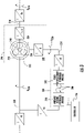
- FIG. 1 a partial view of an exemplary embodiment of an integrated turbo-compressor in accordance with the disclosure is shown in FIG. 1 and is designated generally by reference character 100.
- FIGS. 2-6 Other embodiments of integrated turbo-compressors, internal combustion engines with integrated turbo-compressors, and methods of compounding output of internal combustion engines, are provided in FIGS. 2-6 , as will be described.
- the systems and methods described herein can be used compounding engines carried by vehicles, such as turbo-compounded hybrid-electric engines in aircraft, though the present disclosure is not limited to any particular type of engine or to aircraft in general.
- an internal combustion engine 10 e.g., a gasoline engine or a diesel internal combustion engine
- the internal combustion engine 10 includes an engine body 12, an engine output shaft 14, a combustion air intake port 16, and an engine exhaust port 18.
- the engine body 12 supports the engine output shaft 14, which can be a crank shaft, for rotation relative to the engine body 12.
- the combustion air intake port 16 is connected to the integrated turbo-compressor 100 and is configured to receive therefrom a flow of compressed combustion air 20.
- the exhaust port 18 is connected to the integrated turbo-compressor 100 is configured to communicate thereto an exhaust flow 22, e.g., a combustion product flow.
- the internal combustion engine 10 is carried by an aircraft 24, a rotor 26, e.g., a propeller or a rotor disk, is operably connected to the engine output shaft 14, and an electric motor and battery arrangement 28 is operably connected to the internal combustion engine 10 in a hybrid-electric turbo-compounded engine arrangement 30.
- a rotor 26 e.g., a propeller or a rotor disk
- an electric motor and battery arrangement 28 is operably connected to the internal combustion engine 10 in a hybrid-electric turbo-compounded engine arrangement 30.
- the internal combustion engine 10 is a constant speed turbo-compounded engine.
- the internal combustion engine is a variable speed turbo-compounded engine.
- the integrated turbo-compressor 100 generally includes a compressor 102 with a compressor outlet 104, a turbine 106 with a turbine inlet 108 operatively connected to the compressor by an interconnect shaft 110, and a compounding drive 112.
- the compounding drive 112 includes an output member 114 (shown in FIG. 2 ) and has a variable gear ratio 116 (shown in FIG. 2 ).
- the variable gear ratio 116 couples the output member 114 with the turbine 106 to compound power output 32 of the internal combustion engine 10, which is connected to the compressor outlet 104 and the turbine inlet 108, using a portion of recovered energy 36 from the exhaust flow 22 issued by internal combustion engine 10 and recovered by the turbine 106.
- the turbine 106 is in fluid communication with the internal combustion engine 10 to receive therefrom the exhaust flow 22 and is configured to extract therefrom the recovered energy 36.
- the turbine inlet 108 is connected to an exhaust port 18 of the internal combustion engine 10 by an exhaust duct 118.
- the turbine 106 have fixed turbomachinery geometry 120.
- the turbine 106 can have one or more of fixed inlet guide vanes, fixed serial vanes, and/or fixed outlet vanes. This simplifies both the construction and the operation of the integrated turbo-compressor 100.
- the compressor 102 is in fluid communication with the internal combustion engine 10 and the ambient environment 42.
- the compressor 102 is configured to ingest and compress air from the ambient environment 42 to form the compressed combustion air 20 using a first recovered energy portion 38 of the recovered energy 36 from the exhaust flow 22 provided by the turbine 106.
- the compressed combustion air 20 is communicated to the combustion air intake port 16 of the internal combustion engine 10, which is connected to the compressor outlet 104 by a compressed air duct 122.
- the compressor 102 have fixed turbomachinery geometry 124.
- the compressor 102 can have one or more of fixed inlet guide vanes, fixed serial vanes, and/or fixed outlet vanes. This also simplifies both the construction and the operation of the integrated turbo-compressor 100.
- the interconnect shaft 110 connects the turbine 106 to the compressor 102.
- the interconnect shaft 110 also connects the turbine 106 to the compounding drive 112.
- the interconnect shaft 110 is configured to communicate the recovered energy 36 to the compressor 102 and the engine output shaft 14, respectively. More particularly, the interconnect shaft 110 communicates the first recovered energy portion 38 to the compressor 102 for compressing the compressed combustion air 20, and communicates a second recovered energy portion 40 to the engine output shaft 14 through the compounding drive 112 and through the variable gear ratio 116.
- the compounding drive 112 couples the turbine 106 to engine output shaft 14 and thereby operably connects the turbine 106 to the internal combustion engine 10.
- the compounding drive 112 includes a variable ratio hydraulic pump/motor set 126 (shown in FIG. 2 ) having the variable gear ratio 116. It is contemplated that the variable gear ratio 116 allow the internal combustion engine 10 to operate over a relatively wide range of speeds, temperatures, and/or altitudes.
- the variable gear ratio 116 can also provide the integrated turbo-compressor 100 with a relatively simple arrangement in comparison to turbomachinery with variable geometry.
- the variable gear ratio 116 can provide the integrated turbo-compressor 100 with relatively high efficiency, high reliability, and/or a lightweight arrangement in comparison to alternative turbo-compressor arrangements.
- the compounding drive 112 includes an input member 128, a hydraulic pump/motor set 130, an epicyclical gear arrangement 132.
- the compounding drive 112 also includes an intermediate member 134 and the output member 114.
- the input member 128 is connected to the turbine 106 (shown in FIG. 1 ). More specifically, the input member 128 is connected to both the turbine 106 and the compressor 102 (shown in FIG. 1 ) through the interconnect shaft 110, and receives therefrom the second recovered energy portion 40 provided by the turbine 106.
- the output member 114 is connected to the internal combustion engine 10 (shown in FIG. 1 ). More specifically, the output member 114 is connected to the engine output shaft 14 (shown in FIG. 1 ) to communicate the second recovered energy portion 40 provided by the turbine 106 (shown in FIG. 1 ) to the engine output shaft 14.
- the epicyclical gear arrangement 132 connects the input member 128 to both the output member 114 and the intermediate member 134 via the hydraulic pump/motor set 130.
- the epicyclical gear arrangement 132 is configured as a subtraction module suitable for high-speed applications, i.e., applications where the turbine 106 (shown in FIG. 1 ) rotates are speeds greater than that of the engine output shaft 14 (shown in FIG. 1 ), and generally includes a housing 146, a sun gear 148, and two or more planetary gears 150.
- the epicyclical gear arrangement 132 also includes a ring gear 152 and a planetary gear carrier 154.
- the sun gear 148 is supported for rotation relative to the housing 146 and is fixed in rotation relative to the input member 128.
- the two or more planetary gears 150 are intermeshed between the sun gear 148 and the ring gear 152, and each in turn supported for independent rotation relative to one another by the planetary gear carrier 154.
- the planetary gear carrier 154 is supported for rotation relative to the housing 146 and is fixed in rotation relative to the output member 114.
- the ring gear 152 is supported for rotation relative to the housing 146, is fixed in rotation relative to the intermediate member 134, and is connected therethrough to the hydraulic pump/motor set 130.
- the hydraulic pump/motor set 130 connects the intermediate member 134 to the output member 114 and includes a fixed displacement hydraulic module 142 and a variable displacement hydraulic module 140.
- the fixed displacement hydraulic module 142 is in fluid communication with the variable displacement hydraulic module 140 through a hydraulic circuit 144, which fluidly connects the fixed displacement hydraulic module 142 with the variable displacement hydraulic module 140.
- the fixed displacement hydraulic module 142 is in turn operably associated with the intermediate member 134, and receives mechanical rotation therefrom for pressurizing hydraulic fluid within the hydraulic circuit 144.
- the controller 156 is operatively connected to the hydraulic pump/motor set 130 for throttling flow of the hydraulic fluid through the hydraulic circuit 144, the fixed displacement hydraulic module 142 being operatively connected to variable displacement hydraulic module 140 through the hydraulic circuit 144. As also shown in FIG. 2 , the variable displacement hydraulic module 140 is operatively connected to the output member 114 for applying power therethrough according to the hydraulic fluid received through the hydraulic circuit 144. It is contemplated that either (or both) the fixed displacement hydraulic module 142 and the variable displacement hydraulic module 140 may operate as hydraulic pump or motor according to the direction of hydraulic fluid through hydraulic circuit 144, as shown in FIG. 2 with the solid and dashed arrows identifying the hydraulic circuit 144.
- the turbine 106 (shown in FIG. 1 ) rotates the input member 128 at a rotational speed which varies according to the operating regime of the internal combustion engine 10 (shown in FIG. 1 ), e.g., according to throttle setting.
- Rotation of the input member 128 in turn rotates the sun gear 148, and thereby the planetary gear carrier 154 according to the rotational resistance presented by the ring gear 152 and communicated planetary gears 150.
- the hydraulic circuit be reversible, the hydraulic circuit 144 thereby providing capability for speed trimming.
- the hydraulic circuit 144 communicates pressurized hydraulic fluid to the variable displacement hydraulic module 140 according to the controller 156, which is configured to throttle flow of hydraulic fluid through the hydraulic circuit 144 to present rotation resistance to the input member 128 via the ring gear 152 and the intermeshed planetary gears 150 such that the planetary gear154 carrier 154, and the therethrough the output member 114, rotate at the speed of the engine output shaft 14 (shown in FIG. 1 ), or slightly above the speed of the engine output shaft 14.
- Manipulation of hydraulic fluid flow through the hydraulic circuit 144 in cooperation with the speed subtraction provided by the epicyclical gear arrangement 132, provides the variable gear ratio 116 for compounding the internal combustion engine 10 (shown in FIG. 1 ) using the turbine 106 (shown in FIG. 1 ).
- the controller 156 can include a passive governor module configured to drive the output member 114 to a predetermined engine output shaft speed, such as in embodiments wherein the internal combustion engine 10 is a constant speed internal combustion engine.
- the controller 156 can include an active governor module configured to adjust the rotational speed of the output member 114 to the actual (or desired) speed of the engine output shaft 14, such as in embodiments wherein the internal combustion engine 10 is a variable speed internal combustion engine.
- a compounding drive 212 is shown.
- the compounding drive 212 is similar to the compounding drive 112 (shown in FIG. 1 ) and is additionally configured for a slow-speed turbo-compressor, i.e., a turbo-compressor having a rotational speed that is lower than that of the engine which it compounds.
- the compounding drive 212 includes an input member 228, a hydraulic pump/motor set 230, an epicyclical gear arrangement 232.
- the compounding drive 212 also includes an intermediate member 234 and the output member 214.
- the input member 128 is connected to the turbine 106 (shown in FIG. 1 ). More specifically, the turbine 106 and the interconnect shaft 110, and therethrough to the compressor 102 (shown in FIG. 1 ), and receives therefrom the second recovered energy portion 40 provided by the turbine 106.
- the output member 214 is connected to the internal combustion engine 10 (shown in FIG. 1 ). More specifically, the output member 214 is connected to the engine output shaft 14 (shown in FIG. 1 ) to communicate the second recovered energy portion 40 provided by the turbine 106 (shown in FIG. 1 ) to the engine output shaft 14.
- the hydraulic pump/motor set 230 connects the input member 228 to the output member 214 through the intermediate member 234 and epicyclical gear arrangement 232.
- the hydraulic pump/motor set 230 includes a variable displacement hydraulic module 240 and fixed displacement hydraulic module 242.
- the fixed displacement hydraulic module 242 is in fluid communication with the variable displacement hydraulic module 240 through a hydraulic circuit 244, which fluidly connects the variable displacement hydraulic module 240 with the fixed displacement hydraulic module 242.
- the fixed displacement hydraulic module 242 is connected to the intermediate member 234, and therethrough to the output member 214 through the epicyclical gear arrangement 232.
- the variable displacement hydraulic module 240 is connected to the input member 228, and therethrough to the turbine 106 (shown in FIG. 1 ).
- variable displacement hydraulic module 240 and the fixed displacement hydraulic module 242 can operate as a hydraulic pump or a hydraulic motor, as required by the operation of the internal combustion engine 10 (shown in FIG. 1 ) and turbine 106 (shown in FIG. 1 ).
- the epicyclical gear arrangement 232 is configured as a speed summation module and includes a housing 246, a sun gear 248, and two or more planetary gears 250.
- the epicyclical gear arrangement 232 also includes a ring gear 252 and a planetary gear carrier 254.
- the sun gear 248 is supported for rotation relative to the housing 246 and is fixed in rotation relative to the input member 228.
- the ring gear 252 is supported for rotation relative to the housing 246 and fixed in rotation relative to the intermediate member 234.
- the two or more planetary gears 150 are intermeshed between the sun gear 248 and the ring gear 252, and are supported for independent rotation relative to one another by the planetary gear carrier 254.
- the planetary gear carrier 254 is in supported for rotation relative to the housing 246 and is fixed in rotation relative to the output member 214. It is contemplated that the compounding drive 212 be constructed with gear construction relationships as shown in FIG. 3 in certain embodiments. This is for illustration purposes only and, as will be appreciated by those of skill in the art in view of the present disclosure, other gear construction relationships may be employed by the compounding drive 212.
- the turbine 106 (shown in FIG. 1 ) rotates the input member 228 at a rotational speed which varies according to the operating regime of the internal combustion engine 10 (shown in FIG. 1 ), e.g., according to throttle setting.
- Rotation of the input member 228 also operates the variable displacement hydraulic module 240, pressurizing hydraulic fluid for circulation within the hydraulic circuit 244 according to valve setting commands received form the controller 156, creating the potential to rotate the intermediate member 234 using the fixed displacement hydraulic module 242.
- the hydraulic circuit 244 be both reversible and throttled, the hydraulic circuit 244 thereby providing capability for speed trimming.
- the hydraulic circuit 244 communicates pressurized hydraulic fluid to the fixed displacement hydraulic module 242 according to instructions received from the controller 156.
- the pressurized hydraulic fluid in turn rotates the intermediate member 234, and therethrough the ring gear 252, using the fixed displacement hydraulic module 242 at an intermediate member speed.
- the intermediate member rotational speed is summed with the rotational speed of the input member 228 by the intermeshing of the planetary gears 250, which rotate the planetary gear carrier 254 and therethrough the output member 214 at a rotational speed equivalent to the rotational speed of the input member 228 and the intermediate member 234.
- Manipulation of hydraulic fluid flow through the hydraulic circuit 244, in cooperation with the speed summing provided by the epicyclical gear arrangement 232, provides the variable gear ratio 116 (shown in FIG. 1 ) for compounding the internal combustion engine 10 (shown in FIG. 1 ) using the turbine 106 (shown in FIG. 1 ).
- the controller 156 can include a passive governor module configured to drive the output member 214 to a predetermined engine output shaft speed, such as in embodiments wherein the internal combustion engine 10 (shown in FIG. 1 ) is a constant speed internal combustion engine.
- the controller 156 can include an active governor module configured to adjust the rotational speed of the output member 214 to the actual (or desired) speed of the engine output shaft 14 (shown in FIG. 1 ), such as in embodiments wherein the internal combustion engine 10 is a variable speed internal combustion engine.
- the compounding drive 312 is similar to the compounding drive 112 (shown in FIG. 1 ) and additionally includes a continuously variable transmission 360.
- the continuously variable transmission 360 connects an input member 328 with an output member 314. Connection is through an adjustable input sheave 362, which is fixed in rotation relative to the input member 328, an adjustable output sheave 364, which is fixed in rotation relative to the output member 314.
- a contoured belt 366 connects the adjustable input sheave 362 to the adjustable output sheave 364 for communication of the second recovered energy portion 40 from the interconnect shaft 110 (shown in FIG. 1 ) to the engine output shaft 14 (shown in FIG. 1 ).
- Speed matching is accomplished by changing the effective operating diameter of either (or both) the adjustable input sheave 362 and the adjustable output sheave 364 using a governor module 356. During operation the working diameter of either (or both) the adjustable input sheave 362 and the adjustable output sheave 364 are adjusted to provide a variable gear ratio 316, which matches rotational speed of the output member 314 to rotational speed of the engine output shaft 14 (shown in FIG. 1 ) based on the rotational speed of the turbine 106 (shown in FIG. 1 ). It is to be understood and appreciated that the arrangement of the continuously variable transmission 360 shown in FIG. 4 is for illustration purposes only, and not for limitation, and that other arrangements are possible and remain within the scope of the present disclosure.
- a compounding drive 412 is shown.
- the compounding drive 412 is similar to the compounding drive 112 (shown in FIG. 1 ) and additionally includes a traction drive assembly 460.
- the traction drive assembly 460 connects an input member 428 with an output member 414 using a variable interface surface 462 defined between a normal face 464 and an oblique face 466.
- the normal face 464 is fixed to one of the input member 428 and the output member 414, and the oblique face 466 is fixed to the other of the input member 428 and the output member 414.
- a governor module 456 is operably connected to one (or both) of the input member 428 and the output member 414 to translate one relative to the other, changing size of the interface surface 462, thereby alternating a variable gear ratio 416 of the compounding drive 412. It is to be understood and appreciated that the arrangement of the traction drive assembly 460 shown in FIG. 5 is for illustration purposes only, and not for limitation, and that other arrangements are possible and remain within the scope of the present disclosure.
- a method 500 of compounding output of an internal combustion engine e.g., the internal combustion engine 10 (shown in FIG. 1 ).
- the method 500 includes receiving an engine exhaust flow, e.g., the exhaust flow 22 (shown in FIG. 1 ) of the internal combustion engine 10 (shown in FIG. 1 ), as shown with box 510.
- the method 500 also includes extracting work, i.e., energy, from the received engine exhaust flow using a turbine, e.g., the turbine 106 (shown in FIG. 1 ), as shown with box 520.
- the work extracted by the turbine from the exhaust flow is divided into a first extracted work portion and a second extracted work portion, as shown with box 530.
- the first extracted work portion is applied (communicated) to a compressor, e.g., the compressor 102 (shown in FIG. 1 ), for powering the compressor, as shown with box 530.
- the compressor compresses a flow of combustion air for the internal combustion engine, e.g., the compressed combustion air 20 (shown in FIG. 1 ), which is provided to the internal combustion engine, as also shown with box 530.
- a second extracted work portion is applied (communicated) to the internal combustion engine, as shown with box 540. More specifically, as also shown with box 540, the second extracted work portion is applied to the internal combustion engine to compound output of the internal combustion engine. While the second extracted work portion is applied to compound output of the internal combustion engine a gear ratio used to apply the second extracted work portion is varied, as shown with box 542. In certain embodiments the gear ratio is varied while the internal combustion engine operates at a fixed engine speed, e.g., at a fixed rotational speed of the engine output shaft, as shown with box 550. In accordance with certain embodiments, the gear ratio can be varied while the internal combustion engine operates at a variable engine speed, e.g., at a variable engine output shaft rotational speed, as shown with box 560.
- Turbo-compounded engines can employ piston (or other) engines with a turbine to recover energy from the exhaust, thereby improving fuel economy. This can be done, for example, by connecting a turbine to the engine pneumatically through engine exhaust and mechanically through a gearbox. While generally acceptable, such compounded engines can be difficult to implement in applications where the engine requires operational capability over a wide range of speeds and/altitudes, such as in aircraft, due to the difficulty in optimizing performance of the turbo-compressor across the operating range.
- One way to provide such capability is to employ fixed gear ratios and variable geometry on the turbomachinery.
- variable gear ratio is by provided through an epicyclical differential and a hydraulic pump/motor set.
- speed and direction of rotation of the hydraulic pump/motor provides a speed trimming function, and changes the apparent gear ratio of the overall assembly.
- variable gear ratio is provided using belt drive continuously variable transmission and/or a traction drive assembly. This can provide one or more of operability over relatively large speed, temperature, and altitude ranges. It can also provide a relatively simple mechanical arrangement in relation to variable turbomachinery geometries. Further, compounded engines employing turbo-compressors with variable gear ratios can be relatively lightweight, provide good reliability, and high efficiency in comparison to alternative variable ratio transmission architectures.
Landscapes
- Engineering & Computer Science (AREA)
- General Engineering & Computer Science (AREA)
- Mechanical Engineering (AREA)
- Chemical & Material Sciences (AREA)
- Combustion & Propulsion (AREA)
- Power Engineering (AREA)
- Supercharger (AREA)
Claims (9)
- Verbrennungsmotor, umfassend:einen Motorkörper (12), der eine Motorabtriebswelle (14) trägt und eine Verbrennungslufteinlassöffnung (16) und eine Auslassöffnung (18) aufweist; undeinen integrierten Turboverdichter (100), umfassend:einen Verdichter (102) mit einem Verdichterauslass (104);eine Turbine (106) mit einem Turbineneinlass (108), wobei die Turbine durch eine Verbindungswelle (110) mit dem Verdichter wirkverbunden ist; undeinen Compoundierantrieb (112), der mit der Turbine verbunden ist und ein variables Übersetzungsverhältnis (116) und ein Abtriebsglied (114) aufweist,wobei das variable Übersetzungsverhältnis (116) die Turbine an das Abtriebsglied koppelt, um den Abtrieb eines Verbrennungsmotors unter Verwendung von Energie, die aus einer Abgasströmung (22) wiedererlangt wird, die von dem Verbrennungsmotor (10) empfangen wird, zu compoundieren,wobei der Compoundierantrieb (112) Folgendes umfasst:ein Eingangsglied (128), das mit der Turbine verbunden ist;ein Abtriebsglied (114), das mit dem Eingangsglied verbunden ist; undein Zwischenglied (134), das das Eingangsglied durch eine Planetengetriebeanordnung (132) und einen Hydraulikpumpen/- motorsatz (130) mit dem Abtriebsglied verbindet;wobei der Verdichterauslass (104) mit der Verbrennungslufteinlassöffnung (106) verbunden ist,wobei der Turbineneinlass (108) mit der Motorauslassöffnung (18) verbunden ist, undwobei eine Elektromotor- und Batterieanordnung (28) in einer hybrid-elektrischen turbo-compoundierten Motoranordnung mit der Motorabtriebswelle wirkverbunden ist;wobei der Hydraulikpumpen/-motorsatz (130) Folgendes umfasst:ein Hydraulikmodul (142) mit fester Verschiebung, wobei das Eingangsglied (128) die Turbine (106) mit dem Hydraulikmodul (142) mit fester Verschiebung wirkverbindet; und ein Hydraulikmodul (140) mit variabler Verschiebung in Fluidkommunikation mit dem Hydraulikmodul (142) mit fester Verschiebung über einen Hydraulikkreis (144), wobei das Abtriebsglied (114) über das Hydraulikmodul 140 mit variabler Verschiebung mit dem Hydraulikpumpen/-motorsatz (130) wirkverbunden ist, und wobei das Hydraulikmodul (140) mit variabler Verschiebung entsprechend dem Hydraulikfluid, das durch den Hydraulikkreis (144) empfangen wird, Kraft durch das Abtriebsglied (114) anwendet; undeine Steuerung (156), die über den Fluidkreis (144) mit dem Hydraulikpumpen/-motorsatz (130) wirkverbunden ist, wobei die Steuerung (130) dazu konfiguriert ist, die Strömung des Hydraulikfluids durch den Hydraulikkreis (144) zu drosseln, den Drehwiderstand auf das Eingangsglied (128) derart über die Planetengetriebeanordnung (132) darzustellen, dass sich das Abtriebsglied (114) bei einer Geschwindigkeit der Abtriebswelle (14) dreht, um dadurch auf eine Compoundierantriebsgeschwindigkeit zu der Geschwindigkeit der Abtriebswelle zu passen, wobei die Manipulation der Hydraulikfluidströmung durch den Hydraulikkreis (144) in Zusammenarbeit mit der Planetengetriebeanordnung (132) ein variables Übersetzungsverhältnis zum Compoundieren des Verbrennungsmotors bereitstellt, der die Turbine nutzt.
- Motor nach Anspruch 1, wobei
der Hydraulikpumpen/-motorsatz die Turbine mit dem Abtriebsglied verbindet. - Motor nach Anspruch 1, wobei die Planetengetriebeanordnung innerhalb eines Gehäuses (246) angeordnet ist, wobei die Planetengetriebeanordnung Folgendes umfasst:ein Sonnenrad (248), das das erste bei Drehung relativ zu der Turbine ist;ein Hohlrad (252), das sich um das Sonnenrad herum erstreckt;eine Vielzahl von Planetenrädern (250), die mit dem Sonnenrad und dem Hohlrad verzahnt ist; undeinen Planetenradträger (254), der jedes der Planetenräder zur Drehung unabhängig von der Drehung relativ zueinander trägt, wobei der Planetenradträger bei Drehung relativ zu dem Abtriebsglied fixiert ist;wobei das Sonnenrad, das Hohlrad und der Planetenradträger jeweils zur Drehung relativ zu dem Gehäuse getragen werden.
- Motor nach Anspruch 1, wobei der Compoundierantrieb eine Traktionsantriebsbaugruppe (460) umfasst, die die Verbindungswelle mit dem Abtriebsglied verbindet.
- Motor nach einem der vorhergehenden Ansprüche, wobei die Turbine eine fixierte Turbomaschinengeometrie aufweist, wobei der Verdichter eine fixierte Turbomaschinengeometrie aufweist.
- Motor nach Anspruch 1, wobei der Verbrennungsmotor ein turbo-compoundierter Motor mit konstanter Geschwindigkeit ist oder wobei der Verbrennungsmotor ein turbo-compoundierter Motor mit variabler Geschwindigkeit ist.
- Luftfahrzeug, das den Motor nach einem der vorhergehenden Ansprüche trägt, wobei der Turboverdichter mit einem Rotor wirkverbunden ist.
- Verfahren zum Compoundieren des Abtriebs eines Verbrennungsmotors, wobei der Verbrennungsmotor Folgendes beinhaltet:einen Motorkörper (12), der eine Motorabtriebswelle (14) trägt und eine Verbrennungslufteinlassöffnung (16) und eine Auslassöffnung (18) aufweist; undeinen integrierten Turboverdichter (100), umfassend:einen Verdichter (102) mit einem Verdichterauslass (102);eine Turbine (106) mit einem Turbineneinlass (108),wobei die Turbine durch eine Verbindungswelle (110) mit dem Verdichter wirkverbunden ist; undeinen Compoundierantrieb (112), der mit der Turbine verbunden ist und ein variables Übersetzungsverhältnis (116) und ein Abtriebsglied (114) aufweist,wobei das variable Übersetzungsverhältnis (116) die Turbine an das Abtriebsglied koppelt, um den Abtrieb eines Verbrennungsmotors unter Verwendung von Energie, die aus einer Abgasströmung wiedererlangt wird, die von der Verbrennung empfangen wird, zu compoundieren,wobei der Compoundierantrieb (112) Folgendes umfasst:ein Eingangsglied (128), das mit der Turbine verbunden ist;ein Abtriebsglied (114), das mit dem Eingangsglied verbunden ist; undein Zwischenglied (134), das das Eingangsglied mit dem Abtriebsglied durch eine Planetengetriebeanordnung (132) undeinen Hydraulikpumpen/-motorsatz (130) verbindet;wobei der Verdichterauslass (104) mit der Verbrennungslufteinlassöffnung (106) verbunden ist,wobei der Turbineneinlass (108) mit der Motorauslassöffnung (18) verbunden ist, undwobei die Elektromotor- und Batterieanordnung (28) in einer hybrid-elektrischen turbo-compoundierten Motoranordnung mit der Motorabtriebswelle wirkverbunden ist;wobei der Hydraulikpumpen/-motorsatz (130) Folgendes umfasst:ein Hydraulikmodul (142) mit fester Verschiebung, wobei das Eingangsglied (128) die Turbine (106) mit dem Hydraulikmodul (142) mit fester Verschiebung wirkverbindet; und ein Hydraulikmodul (140) mit variabler Verschiebung in Fluidkommunikation mit dem Hydraulikmodul (142) mit fester Verschiebung über einen Hydraulikkreis (144), wobei das Abtriebsglied (114) über das Hydraulikmodul 140 mit variabler Verschiebung mit dem Hydraulikpumpen/-motorsatz (130) wirkverbunden ist, und wobei das Hydraulikmodul (140) mit variabler Verschiebung entsprechend dem Hydraulikfluid, das durch den Hydraulikkreis (144) empfangen wird, Kraft durch das Abtriebsglied (114) anwendet; undeine Steuerung (156), die über den Fluidkreis (144) mit dem Hydraulikpumpen/-motorsatz (130) wirkverbunden ist, wobei die Steuerung (130) dazu konfiguriert ist, die Strömung des Hydraulikfluids durch den Hydraulikkreis (144) zu drosseln, den Drehwiderstand auf das Eingangsglied (128) derart über die Planetengetriebeanordnung (132) darzustellen, dass sich das Abtriebsglied (114) bei einer Geschwindigkeit der Abtriebswelle (14) dreht, um dadurch auf eine Compoundierantriebsgeschwindigkeit zu der Geschwindigkeit der Abtriebswelle zu passen, wobei die Manipulation der Hydraulikfluidströmung durch den Hydraulikkreis (144) in Zusammenarbeit mit der Planetengetriebeanordnung (132) ein variables Übersetzungsverhältnis zum Compoundieren des Verbrennungsmotors bereitstellt, der die Turbine nutzt;wobei das Verfahren Folgendes umfasst:Empfangen einer Motorabgasströmung von einem Verbrennungsmotor an dem Turbineneinlass;Extrahieren von Arbeiten von der Motorabgasströmung mit der Turbine;Anwenden eines ersten Abschnitts der extrahierten Arbeiten auf den Verdichter, um eine Strömung von Verbrennungsluft für den Verbrennungsmotor zu verdichten; undAnwenden eines zweiten Abschnitts der extrahierten Arbeiten auf den Verbrennungsmotor, um die Ausgabe des Verbrennungsmotors zu compoundieren, wobei das Anwenden des zweiten Abschnitts der extrahierten Arbeiten Variieren des variablen Übersetzungsverhältnisses beim Compoundieren der Ausgabe des Verbrennungsmotors beinhaltet.
- Verfahren nach Anspruch 8, ferner umfassend Variieren des variablen Übersetzungsverhältnisses des Compoundierantriebs bei Drehung der Motorabtriebswelle des Verbrennungsmotors bei einer festen Drehzahl, oder
ferner umfassend Variieren des variablen Übersetzungsverhältnisses des Compoundierantriebs bei Variieren der Drehzahl der Motorabtriebswelle.
Applications Claiming Priority (1)
| Application Number | Priority Date | Filing Date | Title |
|---|---|---|---|
| US16/431,084 US11060449B2 (en) | 2019-06-04 | 2019-06-04 | Integrated turbo-compressor with variable gear ratio transmission for internal combustion engine |
Publications (2)
| Publication Number | Publication Date |
|---|---|
| EP3748143A1 EP3748143A1 (de) | 2020-12-09 |
| EP3748143B1 true EP3748143B1 (de) | 2022-04-27 |
Family
ID=68699227
Family Applications (1)
| Application Number | Title | Priority Date | Filing Date |
|---|---|---|---|
| EP19211660.6A Active EP3748143B1 (de) | 2019-06-04 | 2019-11-26 | Turboverdichter für verbrennungsmotoren |
Country Status (2)
| Country | Link |
|---|---|
| US (1) | US11060449B2 (de) |
| EP (1) | EP3748143B1 (de) |
Families Citing this family (3)
| Publication number | Priority date | Publication date | Assignee | Title |
|---|---|---|---|---|
| FR3099202B1 (fr) * | 2019-07-26 | 2021-07-09 | Safran Aircraft Engines | Dispositif à répartition de puissance entre un démarreur électrique et une machine électrique vers un arbre d’une turbomachine |
| US12152531B1 (en) | 2023-07-31 | 2024-11-26 | Pratt & Whitney Canada Corp. | Transmission assembly for an aircraft engine assembly and architecture for controlling same |
| US12467473B1 (en) * | 2024-11-11 | 2025-11-11 | Pratt & Whitney Canada Corp. | Aircraft engine including diffuser secured to a bearing housing |
Family Cites Families (14)
| Publication number | Priority date | Publication date | Assignee | Title |
|---|---|---|---|---|
| GB206845A (en) * | 1922-11-09 | 1924-02-21 | Heinrich Schneider | Improvements in an internal combustion engine in combination with a gas-turbine driven by the exhaust gases of the engine and driving a compressor |
| US2585968A (en) | 1944-02-21 | 1952-02-19 | Schneider Brothers Company | Turbosupercharged internal-combustion engine having hydraulic means to connect turbine to engine output shaft at high load |
| DE2840375A1 (de) * | 1978-09-16 | 1980-04-10 | Maschf Augsburg Nuernberg Ag | Abgasturbolader fuer dieselmotoren |
| DE3532938C1 (de) * | 1985-09-14 | 1986-09-18 | M.A.N.-B & W Diesel GmbH, 8900 Augsburg | Mittels Abgasturbolader aufgeladene Brennkraftmaschine mit einer Abgasueberschussenergie-Umformeinrichtung |
| AU4257193A (en) * | 1992-04-25 | 1993-11-29 | 577224 Ontario Limited | Turbo compounder |
| GB2300450A (en) * | 1994-01-25 | 1996-11-06 | Komatsu Mfg Co Ltd | Differential driving supercharger and method for controlling the same |
| SE511035C2 (sv) | 1996-04-25 | 1999-07-26 | Volvo Ab | Överladdad förbränningsmotor |
| US7055507B2 (en) | 2004-03-29 | 2006-06-06 | Borgwarner Inc. | Continuously variable drive for superchargers |
| US7490594B2 (en) * | 2004-08-16 | 2009-02-17 | Woodward Governor Company | Super-turbocharger |
| WO2008075127A1 (en) * | 2006-12-19 | 2008-06-26 | Renault Trucks | Power unit for an automotive vehicle and vehicle including such a power unit |
| DE102008053383A1 (de) * | 2007-11-23 | 2009-05-28 | Luk Lamellen Und Kupplungsbau Beteiligungs Kg | Kompressorantriebsanordnung mit variabler Drehzahl |
| US8561403B2 (en) * | 2008-08-05 | 2013-10-22 | Vandyne Super Turbo, Inc. | Super-turbocharger having a high speed traction drive and a continuously variable transmission |
| DE102013000495B3 (de) | 2013-01-15 | 2014-03-13 | Voith Patent Gmbh | Antriebsstrang, insbesondere für ein Kraftfahrzeug |
| US10384525B2 (en) * | 2017-02-02 | 2019-08-20 | FEV Europe GmbH | Systems for power integration of turbines, compressors and hybrid energy devices with internal combustion engines |
-
2019
- 2019-06-04 US US16/431,084 patent/US11060449B2/en active Active
- 2019-11-26 EP EP19211660.6A patent/EP3748143B1/de active Active
Also Published As
| Publication number | Publication date |
|---|---|
| US20200386149A1 (en) | 2020-12-10 |
| US11060449B2 (en) | 2021-07-13 |
| EP3748143A1 (de) | 2020-12-09 |
Similar Documents
| Publication | Publication Date | Title |
|---|---|---|
| US11408352B2 (en) | Reverse-flow gas turbine engine | |
| CN107407207B (zh) | 具有同轴压缩机和偏移涡轮机部段的复合发动机组件 | |
| US4916893A (en) | Multipurpose auxiliary power unit | |
| EP3748143B1 (de) | Turboverdichter für verbrennungsmotoren | |
| EP3260688A1 (de) | Kammerkühlung für einen gasturbinenmotor | |
| CN107532548B (zh) | 具有公共入口的复合发动机组件 | |
| EP3321488A1 (de) | Zubehöranordnung für gasturbinenmotor | |
| CN107636295A (zh) | 具有选择阀的发动机进气组件 | |
| RU2659133C2 (ru) | Турбовентиляторный редукторный двигатель, оснащенный системой низкого давления для контроля за средой летательного аппарата | |
| CN112739901A (zh) | 包括电源装置的涡轮反应器 | |
| CN108087149B (zh) | 一种高推重比低油耗的涡喷发动机 | |
| EP2573356B1 (de) | Turboaufladungssystem und Betriebsverfahren dafür | |
| CN107923310B (zh) | 复合循环发动机 | |
| CN112739896A (zh) | 具有减速机构的涡轮喷气发动机 | |
| CN113847164A (zh) | 一种由电机带转增压级实现变涵道比的航空发动机及其控制方法 | |
| CN104775900B (zh) | 复合循环发动机 | |
| CN109139234B (zh) | 带有中间冷却器的发动机组件 | |
| CA3069189A1 (en) | Gas turbine engine with power turbine driven boost compressor | |
| EP3789594B1 (de) | Verbrennungsmotoren mit unidirektionalen kompoundierungsantrieben | |
| US10273826B2 (en) | Lubrication device for a turbine engine | |
| JPS60116821A (ja) | 排気タ−ビン過給機 | |
| WO2016198854A1 (en) | Pulse-optimized flow control | |
| US11629612B2 (en) | System for feeding operating gas to a drive of a motor vehicle | |
| AU2013325122B2 (en) | Thrust propulsion system | |
| EP4310303A1 (de) | System mit mehreren zwangsinduktionsmotoren |
Legal Events
| Date | Code | Title | Description |
|---|---|---|---|
| PUAI | Public reference made under article 153(3) epc to a published international application that has entered the european phase |
Free format text: ORIGINAL CODE: 0009012 |
|
| STAA | Information on the status of an ep patent application or granted ep patent |
Free format text: STATUS: THE APPLICATION HAS BEEN PUBLISHED |
|
| AK | Designated contracting states |
Kind code of ref document: A1 Designated state(s): AL AT BE BG CH CY CZ DE DK EE ES FI FR GB GR HR HU IE IS IT LI LT LU LV MC MK MT NL NO PL PT RO RS SE SI SK SM TR |
|
| AX | Request for extension of the european patent |
Extension state: BA ME |
|
| STAA | Information on the status of an ep patent application or granted ep patent |
Free format text: STATUS: REQUEST FOR EXAMINATION WAS MADE |
|
| 17P | Request for examination filed |
Effective date: 20210609 |
|
| RBV | Designated contracting states (corrected) |
Designated state(s): AL AT BE BG CH CY CZ DE DK EE ES FI FR GB GR HR HU IE IS IT LI LT LU LV MC MK MT NL NO PL PT RO RS SE SI SK SM TR |
|
| RIC1 | Information provided on ipc code assigned before grant |
Ipc: F02B 41/10 20060101AFI20211007BHEP |
|
| GRAP | Despatch of communication of intention to grant a patent |
Free format text: ORIGINAL CODE: EPIDOSNIGR1 |
|
| STAA | Information on the status of an ep patent application or granted ep patent |
Free format text: STATUS: GRANT OF PATENT IS INTENDED |
|
| INTG | Intention to grant announced |
Effective date: 20211122 |
|
| RIN1 | Information on inventor provided before grant (corrected) |
Inventor name: THOMASSIN, JEAN Inventor name: LEMMERS, GLENN C. JR. Inventor name: BEHLING, DAVID S. Inventor name: SPIERLING, TODD A. |
|
| GRAS | Grant fee paid |
Free format text: ORIGINAL CODE: EPIDOSNIGR3 |
|
| GRAA | (expected) grant |
Free format text: ORIGINAL CODE: 0009210 |
|
| STAA | Information on the status of an ep patent application or granted ep patent |
Free format text: STATUS: THE PATENT HAS BEEN GRANTED |
|
| AK | Designated contracting states |
Kind code of ref document: B1 Designated state(s): AL AT BE BG CH CY CZ DE DK EE ES FI FR GB GR HR HU IE IS IT LI LT LU LV MC MK MT NL NO PL PT RO RS SE SI SK SM TR |
|
| REG | Reference to a national code |
Ref country code: GB Ref legal event code: FG4D |
|
| REG | Reference to a national code |
Ref country code: CH Ref legal event code: EP |
|
| REG | Reference to a national code |
Ref country code: DE Ref legal event code: R096 Ref document number: 602019014103 Country of ref document: DE |
|
| REG | Reference to a national code |
Ref country code: AT Ref legal event code: REF Ref document number: 1487091 Country of ref document: AT Kind code of ref document: T Effective date: 20220515 |
|
| REG | Reference to a national code |
Ref country code: IE Ref legal event code: FG4D |
|
| REG | Reference to a national code |
Ref country code: LT Ref legal event code: MG9D |
|
| REG | Reference to a national code |
Ref country code: NL Ref legal event code: MP Effective date: 20220427 |
|
| REG | Reference to a national code |
Ref country code: AT Ref legal event code: MK05 Ref document number: 1487091 Country of ref document: AT Kind code of ref document: T Effective date: 20220427 |
|
| PG25 | Lapsed in a contracting state [announced via postgrant information from national office to epo] |
Ref country code: NL Free format text: LAPSE BECAUSE OF FAILURE TO SUBMIT A TRANSLATION OF THE DESCRIPTION OR TO PAY THE FEE WITHIN THE PRESCRIBED TIME-LIMIT Effective date: 20220427 |
|
| PG25 | Lapsed in a contracting state [announced via postgrant information from national office to epo] |
Ref country code: SE Free format text: LAPSE BECAUSE OF FAILURE TO SUBMIT A TRANSLATION OF THE DESCRIPTION OR TO PAY THE FEE WITHIN THE PRESCRIBED TIME-LIMIT Effective date: 20220427 Ref country code: PT Free format text: LAPSE BECAUSE OF FAILURE TO SUBMIT A TRANSLATION OF THE DESCRIPTION OR TO PAY THE FEE WITHIN THE PRESCRIBED TIME-LIMIT Effective date: 20220829 Ref country code: NO Free format text: LAPSE BECAUSE OF FAILURE TO SUBMIT A TRANSLATION OF THE DESCRIPTION OR TO PAY THE FEE WITHIN THE PRESCRIBED TIME-LIMIT Effective date: 20220727 Ref country code: LT Free format text: LAPSE BECAUSE OF FAILURE TO SUBMIT A TRANSLATION OF THE DESCRIPTION OR TO PAY THE FEE WITHIN THE PRESCRIBED TIME-LIMIT Effective date: 20220427 Ref country code: HR Free format text: LAPSE BECAUSE OF FAILURE TO SUBMIT A TRANSLATION OF THE DESCRIPTION OR TO PAY THE FEE WITHIN THE PRESCRIBED TIME-LIMIT Effective date: 20220427 Ref country code: GR Free format text: LAPSE BECAUSE OF FAILURE TO SUBMIT A TRANSLATION OF THE DESCRIPTION OR TO PAY THE FEE WITHIN THE PRESCRIBED TIME-LIMIT Effective date: 20220728 Ref country code: FI Free format text: LAPSE BECAUSE OF FAILURE TO SUBMIT A TRANSLATION OF THE DESCRIPTION OR TO PAY THE FEE WITHIN THE PRESCRIBED TIME-LIMIT Effective date: 20220427 Ref country code: BG Free format text: LAPSE BECAUSE OF FAILURE TO SUBMIT A TRANSLATION OF THE DESCRIPTION OR TO PAY THE FEE WITHIN THE PRESCRIBED TIME-LIMIT Effective date: 20220727 Ref country code: AT Free format text: LAPSE BECAUSE OF FAILURE TO SUBMIT A TRANSLATION OF THE DESCRIPTION OR TO PAY THE FEE WITHIN THE PRESCRIBED TIME-LIMIT Effective date: 20220427 |
|
| PG25 | Lapsed in a contracting state [announced via postgrant information from national office to epo] |
Ref country code: RS Free format text: LAPSE BECAUSE OF FAILURE TO SUBMIT A TRANSLATION OF THE DESCRIPTION OR TO PAY THE FEE WITHIN THE PRESCRIBED TIME-LIMIT Effective date: 20220427 Ref country code: PL Free format text: LAPSE BECAUSE OF FAILURE TO SUBMIT A TRANSLATION OF THE DESCRIPTION OR TO PAY THE FEE WITHIN THE PRESCRIBED TIME-LIMIT Effective date: 20220427 Ref country code: LV Free format text: LAPSE BECAUSE OF FAILURE TO SUBMIT A TRANSLATION OF THE DESCRIPTION OR TO PAY THE FEE WITHIN THE PRESCRIBED TIME-LIMIT Effective date: 20220427 Ref country code: IS Free format text: LAPSE BECAUSE OF FAILURE TO SUBMIT A TRANSLATION OF THE DESCRIPTION OR TO PAY THE FEE WITHIN THE PRESCRIBED TIME-LIMIT Effective date: 20220827 |
|
| REG | Reference to a national code |
Ref country code: DE Ref legal event code: R097 Ref document number: 602019014103 Country of ref document: DE |
|
| PG25 | Lapsed in a contracting state [announced via postgrant information from national office to epo] |
Ref country code: SM Free format text: LAPSE BECAUSE OF FAILURE TO SUBMIT A TRANSLATION OF THE DESCRIPTION OR TO PAY THE FEE WITHIN THE PRESCRIBED TIME-LIMIT Effective date: 20220427 Ref country code: SK Free format text: LAPSE BECAUSE OF FAILURE TO SUBMIT A TRANSLATION OF THE DESCRIPTION OR TO PAY THE FEE WITHIN THE PRESCRIBED TIME-LIMIT Effective date: 20220427 Ref country code: RO Free format text: LAPSE BECAUSE OF FAILURE TO SUBMIT A TRANSLATION OF THE DESCRIPTION OR TO PAY THE FEE WITHIN THE PRESCRIBED TIME-LIMIT Effective date: 20220427 Ref country code: ES Free format text: LAPSE BECAUSE OF FAILURE TO SUBMIT A TRANSLATION OF THE DESCRIPTION OR TO PAY THE FEE WITHIN THE PRESCRIBED TIME-LIMIT Effective date: 20220427 Ref country code: EE Free format text: LAPSE BECAUSE OF FAILURE TO SUBMIT A TRANSLATION OF THE DESCRIPTION OR TO PAY THE FEE WITHIN THE PRESCRIBED TIME-LIMIT Effective date: 20220427 Ref country code: DK Free format text: LAPSE BECAUSE OF FAILURE TO SUBMIT A TRANSLATION OF THE DESCRIPTION OR TO PAY THE FEE WITHIN THE PRESCRIBED TIME-LIMIT Effective date: 20220427 Ref country code: CZ Free format text: LAPSE BECAUSE OF FAILURE TO SUBMIT A TRANSLATION OF THE DESCRIPTION OR TO PAY THE FEE WITHIN THE PRESCRIBED TIME-LIMIT Effective date: 20220427 |
|
| PLBE | No opposition filed within time limit |
Free format text: ORIGINAL CODE: 0009261 |
|
| STAA | Information on the status of an ep patent application or granted ep patent |
Free format text: STATUS: NO OPPOSITION FILED WITHIN TIME LIMIT |
|
| PG25 | Lapsed in a contracting state [announced via postgrant information from national office to epo] |
Ref country code: AL Free format text: LAPSE BECAUSE OF FAILURE TO SUBMIT A TRANSLATION OF THE DESCRIPTION OR TO PAY THE FEE WITHIN THE PRESCRIBED TIME-LIMIT Effective date: 20220427 |
|
| 26N | No opposition filed |
Effective date: 20230130 |
|
| PG25 | Lapsed in a contracting state [announced via postgrant information from national office to epo] |
Ref country code: SI Free format text: LAPSE BECAUSE OF FAILURE TO SUBMIT A TRANSLATION OF THE DESCRIPTION OR TO PAY THE FEE WITHIN THE PRESCRIBED TIME-LIMIT Effective date: 20220427 |
|
| PG25 | Lapsed in a contracting state [announced via postgrant information from national office to epo] |
Ref country code: MC Free format text: LAPSE BECAUSE OF FAILURE TO SUBMIT A TRANSLATION OF THE DESCRIPTION OR TO PAY THE FEE WITHIN THE PRESCRIBED TIME-LIMIT Effective date: 20220427 |
|
| REG | Reference to a national code |
Ref country code: CH Ref legal event code: PL |
|
| P01 | Opt-out of the competence of the unified patent court (upc) registered |
Effective date: 20230603 |
|
| REG | Reference to a national code |
Ref country code: BE Ref legal event code: MM Effective date: 20221130 |
|
| PG25 | Lapsed in a contracting state [announced via postgrant information from national office to epo] |
Ref country code: LI Free format text: LAPSE BECAUSE OF NON-PAYMENT OF DUE FEES Effective date: 20221130 Ref country code: CH Free format text: LAPSE BECAUSE OF NON-PAYMENT OF DUE FEES Effective date: 20221130 |
|
| PG25 | Lapsed in a contracting state [announced via postgrant information from national office to epo] |
Ref country code: LU Free format text: LAPSE BECAUSE OF NON-PAYMENT OF DUE FEES Effective date: 20221126 |
|
| PG25 | Lapsed in a contracting state [announced via postgrant information from national office to epo] |
Ref country code: IE Free format text: LAPSE BECAUSE OF NON-PAYMENT OF DUE FEES Effective date: 20221126 |
|
| PG25 | Lapsed in a contracting state [announced via postgrant information from national office to epo] |
Ref country code: BE Free format text: LAPSE BECAUSE OF NON-PAYMENT OF DUE FEES Effective date: 20221130 |
|
| PG25 | Lapsed in a contracting state [announced via postgrant information from national office to epo] |
Ref country code: IT Free format text: LAPSE BECAUSE OF FAILURE TO SUBMIT A TRANSLATION OF THE DESCRIPTION OR TO PAY THE FEE WITHIN THE PRESCRIBED TIME-LIMIT Effective date: 20220427 |
|
| PG25 | Lapsed in a contracting state [announced via postgrant information from national office to epo] |
Ref country code: CY Free format text: LAPSE BECAUSE OF FAILURE TO SUBMIT A TRANSLATION OF THE DESCRIPTION OR TO PAY THE FEE WITHIN THE PRESCRIBED TIME-LIMIT Effective date: 20220427 |
|
| PG25 | Lapsed in a contracting state [announced via postgrant information from national office to epo] |
Ref country code: MK Free format text: LAPSE BECAUSE OF FAILURE TO SUBMIT A TRANSLATION OF THE DESCRIPTION OR TO PAY THE FEE WITHIN THE PRESCRIBED TIME-LIMIT Effective date: 20220427 Ref country code: HU Free format text: LAPSE BECAUSE OF FAILURE TO SUBMIT A TRANSLATION OF THE DESCRIPTION OR TO PAY THE FEE WITHIN THE PRESCRIBED TIME-LIMIT; INVALID AB INITIO Effective date: 20191126 |
|
| PG25 | Lapsed in a contracting state [announced via postgrant information from national office to epo] |
Ref country code: TR Free format text: LAPSE BECAUSE OF FAILURE TO SUBMIT A TRANSLATION OF THE DESCRIPTION OR TO PAY THE FEE WITHIN THE PRESCRIBED TIME-LIMIT Effective date: 20220427 |
|
| PG25 | Lapsed in a contracting state [announced via postgrant information from national office to epo] |
Ref country code: MT Free format text: LAPSE BECAUSE OF FAILURE TO SUBMIT A TRANSLATION OF THE DESCRIPTION OR TO PAY THE FEE WITHIN THE PRESCRIBED TIME-LIMIT Effective date: 20220427 |
|
| PG25 | Lapsed in a contracting state [announced via postgrant information from national office to epo] |
Ref country code: BG Free format text: LAPSE BECAUSE OF FAILURE TO SUBMIT A TRANSLATION OF THE DESCRIPTION OR TO PAY THE FEE WITHIN THE PRESCRIBED TIME-LIMIT Effective date: 20220427 |
|
| PG25 | Lapsed in a contracting state [announced via postgrant information from national office to epo] |
Ref country code: BG Free format text: LAPSE BECAUSE OF FAILURE TO SUBMIT A TRANSLATION OF THE DESCRIPTION OR TO PAY THE FEE WITHIN THE PRESCRIBED TIME-LIMIT Effective date: 20220427 |
|
| PGFP | Annual fee paid to national office [announced via postgrant information from national office to epo] |
Ref country code: DE Payment date: 20251022 Year of fee payment: 7 |
|
| PGFP | Annual fee paid to national office [announced via postgrant information from national office to epo] |
Ref country code: GB Payment date: 20251022 Year of fee payment: 7 |
|
| PGFP | Annual fee paid to national office [announced via postgrant information from national office to epo] |
Ref country code: FR Payment date: 20251022 Year of fee payment: 7 |