EP3748193A2 - Agencement de serrage pourvu de rouleau de serrage et dispositif de réglage d'un agencement de serrage - Google Patents
Agencement de serrage pourvu de rouleau de serrage et dispositif de réglage d'un agencement de serrage Download PDFInfo
- Publication number
- EP3748193A2 EP3748193A2 EP20176190.5A EP20176190A EP3748193A2 EP 3748193 A2 EP3748193 A2 EP 3748193A2 EP 20176190 A EP20176190 A EP 20176190A EP 3748193 A2 EP3748193 A2 EP 3748193A2
- Authority
- EP
- European Patent Office
- Prior art keywords
- bearing
- clamping
- tensioning
- arrangement according
- clamping arrangement
- Prior art date
- Legal status (The legal status is an assumption and is not a legal conclusion. Google has not performed a legal analysis and makes no representation as to the accuracy of the status listed.)
- Withdrawn
Links
Images


Classifications
-
- F—MECHANICAL ENGINEERING; LIGHTING; HEATING; WEAPONS; BLASTING
- F16—ENGINEERING ELEMENTS AND UNITS; GENERAL MEASURES FOR PRODUCING AND MAINTAINING EFFECTIVE FUNCTIONING OF MACHINES OR INSTALLATIONS; THERMAL INSULATION IN GENERAL
- F16H—GEARING
- F16H7/00—Gearings for conveying rotary motion by endless flexible members
- F16H7/08—Means for varying tension of belts, ropes or chains
- F16H7/10—Means for varying tension of belts, ropes or chains by adjusting the axis of a pulley
- F16H7/12—Means for varying tension of belts, ropes or chains by adjusting the axis of a pulley of an idle pulley
- F16H7/1254—Means for varying tension of belts, ropes or chains by adjusting the axis of a pulley of an idle pulley without vibration damping means
- F16H7/1281—Means for varying tension of belts, ropes or chains by adjusting the axis of a pulley of an idle pulley without vibration damping means where the axis of the pulley moves along a substantially circular path
-
- F—MECHANICAL ENGINEERING; LIGHTING; HEATING; WEAPONS; BLASTING
- F16—ENGINEERING ELEMENTS AND UNITS; GENERAL MEASURES FOR PRODUCING AND MAINTAINING EFFECTIVE FUNCTIONING OF MACHINES OR INSTALLATIONS; THERMAL INSULATION IN GENERAL
- F16H—GEARING
- F16H7/00—Gearings for conveying rotary motion by endless flexible members
- F16H7/08—Means for varying tension of belts, ropes or chains
- F16H7/10—Means for varying tension of belts, ropes or chains by adjusting the axis of a pulley
- F16H7/12—Means for varying tension of belts, ropes or chains by adjusting the axis of a pulley of an idle pulley
- F16H7/1254—Means for varying tension of belts, ropes or chains by adjusting the axis of a pulley of an idle pulley without vibration damping means
-
- F—MECHANICAL ENGINEERING; LIGHTING; HEATING; WEAPONS; BLASTING
- F16—ENGINEERING ELEMENTS AND UNITS; GENERAL MEASURES FOR PRODUCING AND MAINTAINING EFFECTIVE FUNCTIONING OF MACHINES OR INSTALLATIONS; THERMAL INSULATION IN GENERAL
- F16H—GEARING
- F16H7/00—Gearings for conveying rotary motion by endless flexible members
- F16H7/02—Gearings for conveying rotary motion by endless flexible members with belts; with V-belts
-
- F—MECHANICAL ENGINEERING; LIGHTING; HEATING; WEAPONS; BLASTING
- F16—ENGINEERING ELEMENTS AND UNITS; GENERAL MEASURES FOR PRODUCING AND MAINTAINING EFFECTIVE FUNCTIONING OF MACHINES OR INSTALLATIONS; THERMAL INSULATION IN GENERAL
- F16H—GEARING
- F16H7/00—Gearings for conveying rotary motion by endless flexible members
- F16H7/08—Means for varying tension of belts, ropes or chains
- F16H7/10—Means for varying tension of belts, ropes or chains by adjusting the axis of a pulley
- F16H7/12—Means for varying tension of belts, ropes or chains by adjusting the axis of a pulley of an idle pulley
-
- F—MECHANICAL ENGINEERING; LIGHTING; HEATING; WEAPONS; BLASTING
- F16—ENGINEERING ELEMENTS AND UNITS; GENERAL MEASURES FOR PRODUCING AND MAINTAINING EFFECTIVE FUNCTIONING OF MACHINES OR INSTALLATIONS; THERMAL INSULATION IN GENERAL
- F16H—GEARING
- F16H7/00—Gearings for conveying rotary motion by endless flexible members
- F16H7/08—Means for varying tension of belts, ropes or chains
- F16H2007/0802—Actuators for final output members
- F16H2007/0804—Leaf springs
-
- F—MECHANICAL ENGINEERING; LIGHTING; HEATING; WEAPONS; BLASTING
- F16—ENGINEERING ELEMENTS AND UNITS; GENERAL MEASURES FOR PRODUCING AND MAINTAINING EFFECTIVE FUNCTIONING OF MACHINES OR INSTALLATIONS; THERMAL INSULATION IN GENERAL
- F16H—GEARING
- F16H7/00—Gearings for conveying rotary motion by endless flexible members
- F16H7/08—Means for varying tension of belts, ropes or chains
- F16H2007/0842—Mounting or support of tensioner
-
- F—MECHANICAL ENGINEERING; LIGHTING; HEATING; WEAPONS; BLASTING
- F16—ENGINEERING ELEMENTS AND UNITS; GENERAL MEASURES FOR PRODUCING AND MAINTAINING EFFECTIVE FUNCTIONING OF MACHINES OR INSTALLATIONS; THERMAL INSULATION IN GENERAL
- F16H—GEARING
- F16H7/00—Gearings for conveying rotary motion by endless flexible members
- F16H7/08—Means for varying tension of belts, ropes or chains
- F16H2007/0863—Finally actuated members, e.g. constructional details thereof
- F16H2007/0865—Pulleys
-
- F—MECHANICAL ENGINEERING; LIGHTING; HEATING; WEAPONS; BLASTING
- F16—ENGINEERING ELEMENTS AND UNITS; GENERAL MEASURES FOR PRODUCING AND MAINTAINING EFFECTIVE FUNCTIONING OF MACHINES OR INSTALLATIONS; THERMAL INSULATION IN GENERAL
- F16H—GEARING
- F16H7/00—Gearings for conveying rotary motion by endless flexible members
- F16H7/08—Means for varying tension of belts, ropes or chains
- F16H2007/0863—Finally actuated members, e.g. constructional details thereof
- F16H2007/0874—Two or more finally actuated members
-
- F—MECHANICAL ENGINEERING; LIGHTING; HEATING; WEAPONS; BLASTING
- F16—ENGINEERING ELEMENTS AND UNITS; GENERAL MEASURES FOR PRODUCING AND MAINTAINING EFFECTIVE FUNCTIONING OF MACHINES OR INSTALLATIONS; THERMAL INSULATION IN GENERAL
- F16H—GEARING
- F16H7/00—Gearings for conveying rotary motion by endless flexible members
- F16H7/08—Means for varying tension of belts, ropes or chains
- F16H2007/0876—Control or adjustment of actuators
-
- F—MECHANICAL ENGINEERING; LIGHTING; HEATING; WEAPONS; BLASTING
- F16—ENGINEERING ELEMENTS AND UNITS; GENERAL MEASURES FOR PRODUCING AND MAINTAINING EFFECTIVE FUNCTIONING OF MACHINES OR INSTALLATIONS; THERMAL INSULATION IN GENERAL
- F16H—GEARING
- F16H7/00—Gearings for conveying rotary motion by endless flexible members
- F16H7/08—Means for varying tension of belts, ropes or chains
- F16H2007/0889—Path of movement of the finally actuated member
- F16H2007/0893—Circular path
-
- F—MECHANICAL ENGINEERING; LIGHTING; HEATING; WEAPONS; BLASTING
- F16—ENGINEERING ELEMENTS AND UNITS; GENERAL MEASURES FOR PRODUCING AND MAINTAINING EFFECTIVE FUNCTIONING OF MACHINES OR INSTALLATIONS; THERMAL INSULATION IN GENERAL
- F16H—GEARING
- F16H7/00—Gearings for conveying rotary motion by endless flexible members
- F16H7/08—Means for varying tension of belts, ropes or chains
- F16H2007/0889—Path of movement of the finally actuated member
- F16H2007/0897—External to internal direction
Definitions
- the invention relates to a clamping arrangement for a traction drive.
- a traction mechanism usually comprises an endless traction mechanism and at least two drive pulleys, one of which can function as a drive and one as an output of the traction mechanism.
- Such traction drives are used, for example, on internal combustion engines of a motor vehicle to drive ancillary units, a first drive pulley sitting on the crankshaft of the internal combustion engine and driving the traction device.
- Further drive pulleys are assigned to the auxiliary units, such as water pumps, alternators or air conditioning compressors, and are driven in rotation by the traction drive.
- the ancillary units are designed as consumers, that is, they are driven by the drive pulley of the crankshaft via the traction mechanism.
- the slack drum is formed between the crankshaft and the unit, usually the generator, which is adjacent in the direction of rotation of the traction mechanism.
- the traction mechanism is pretensioned by means of a tensioning roller of the tensioning arrangement.
- a traction mechanism can react more or less sensitively to an incorrect position on a drive pulley. This applies in particular to the drive pulley in the strand before it enters a generator. This can lead to an undesired axial running behavior of the traction mechanism, which can lead to negative effects such as traction mechanism wear or noise.
- the tensioning arrangement comprises a plurality of disks that are drive-connected via a traction mechanism, one of which is connected to an assembly of the internal combustion engine.
- a traction mechanism On both sides of the disk connected to the unit, two tensioning elements are arranged which are mounted on a common lever. The tensioning elements are each pretensioned against the traction means via the lever by means of a tensioning unit.
- a roller of the tensioning element guiding the traction mechanism is convex and is mounted in the lever so that it can be tilted or moved axially about a vertical axis.
- the tensioning device comprises a base body, a tensioning arm with a bearing support and a tensioning roller, which is pivotably mounted relative to the base body, and spring means for loading the tensioning arm.
- An adjusting device is provided for adjusting a spring support relative to the bearing bracket of the tensioning roller.
- a tensioning device for a traction means which has a receiving housing, a roller carrier with a tensioning roller, a bearing arrangement with which the roller carrier is rotatably mounted in the receiving housing about an axis of rotation, and a helical tension spring, which is attached to the receiving housing and the roller carrier in the circumferential direction and is supported in the axial direction, has.
- the present invention is based on the object of proposing a tensioning arrangement which enables good running behavior of the traction means on the tensioning roller and has a long service life.
- the object is also to propose a corresponding adjustment device with which such a clamping arrangement can be adjusted.
- a tensioning arrangement for a traction drive comprising: a base body; at least one clamping arm which is mounted so as to be pivotable relative to the base body about a pivot axis; a tensioning roller which is connected to a support element of the at least one tensioning arm so as to be rotatable about an axis of rotation by means of a bearing; and an adjusting mechanism which is designed to pivot the bearing relative to the carrier element in a pivoting range and to fix it in a pivoting position within the pivoting range.
- tensioning arrangement is that the bearing or the tensioning roller mounted rotatably with it can be adjusted relative to the carrier element or the base body of the tensioning arrangement by means of the adjustment mechanism.
- a defined inclination of the tensioning roller relative to the roller carrier or base body can be achieved in a simple and inexpensive manner, wherein the inclination can also be zero.
- the defined alignment or the defined inclination can be maintained within very narrow tolerances, so that when the clamping arrangement is in operation, the tensioning roller has a high positional accuracy relative to the traction mechanism.
- the defined alignment or the defined inclination can also include pre-tilting within the narrow tolerances.
- the tensioning arrangement is used to tension a traction mechanism of a traction mechanism drive.
- the traction drive is designed to transmit torque between two or more shafts with the aid of the endless traction.
- the traction mechanism drive can be designed in the form of a belt drive, toothed belt drive or chain drive.
- the tensioning arrangement can accordingly be designed in the form of a belt tensioning arrangement or a chain tensioning arrangement.
- the tension pulley can be adjusted and fixed in relation to the carrier element within a defined adjustment range. It is provided in particular that the tension roller bearing can be pivoted with its axis of rotation relative to a carrier axis (A12) of the carrier element in a limited pivoting range.
- the carrier axis (A12) runs in particular parallel to the pivot axis (A4, A6) of the clamping arm through the bearing center point (C) of the tension roller bearing.
- the adjustment mechanism is designed in particular so that the tensioning roller can be pivoted at least in one pivot plane (Ea) which, in an axial view of the carrier axis (A12) within an angular range ( ⁇ ) of up to ⁇ 30 ° around the carrier axis (A12) relative to a Tangent plane (T).
- the tangent plane (T) can be defined as a plane perpendicular to the radius (R), which extends from the pivot axis (A4) to the carrier axis (A12) or to the bearing center point (C).
- the adjustment mechanism can also be designed in such a way that the axis of rotation (A5) can be pivoted relative to the carrier axis (A12) - in an axial view of the carrier axis (A12) - also within larger angular ranges ( ⁇ ), in particular into each Pivot direction around the carrier axis (A12), that over 360 ° around the carrier axis.
- the setting mechanism can comprise a bearing receptacle in which the bearing is received, a support element against which the bearing receptacle is axially supported, and a clamping element for bracing the bearing receptacle against the support element.
- the bearing receptacle In the unstressed state of the tensioning element, the bearing receptacle can be pivoted relative to the support element, so that the bearing or the tensioning roller can be adjusted to the desired position relative to the support element.
- the bearing receptacle or the tensioning roller mounted therein is fixed in the desired position relative to the support element or the roller carrier.
- the bearing receptacle On the side facing the carrier element, the bearing receptacle can have a contact surface which is in contact with a support surface of the support element.
- the contact surface of the bearing receptacle or the support surface of the support element are designed such that the bearing receptacle can be pivoted and brought into contact in various positions relative to the support element.
- at least one of the contact surface and the support surface can be designed spherically, with both surfaces preferably being designed spherically.
- the support surface is preferably designed concave, while the contact surface is preferably designed convex.
- the bearing receptacle On the side facing away from the carrier element, the bearing receptacle can have a pressure surface, which can be brought into contact with a clamping surface of the clamping element or can be acted upon by this.
- the pressure surface of the bearing receptacle or the clamping surface of the clamping element are designed such that the bearing receptacle can be pivoted in different positions relative to the clamping element and can be acted upon by the latter.
- at least one of the pressure surface and the clamping surface can be designed spherically, both surfaces preferably being designed spherically.
- the bearing can be pivotable relative to the carrier element about a pivot point which lies within the axial extent of the bearing.
- the pressure surface is preferably convex and the contact surface is preferably concave.
- a radius of the spherical surface can be smaller than a largest outer radius of the tensioning roller, in particular smaller than a largest outer radius of the bearing.
- the pairings of surfaces are designed in such a way that overall a spherical structure of the bearing receptacle results, the pivot point resulting from the pairings of surfaces preferably lying in the central plane of the bearing.
- the bearing can be pivoted relative to the carrier element about a fulcrum which lies outside the axial extent of the bearing, in particular on a side opposite to the base body in relation to a bearing center plane.
- the pressure surface is preferably concave and the contact surface is preferably convex.
- a radius of the spherical surface can be larger than a largest outer radius of the bearing, in particular greater than a largest outer radius of the tensioning roller.
- the pairings of surfaces are designed in such a way that overall a double-spherical structure of the bearing receptacle results, the fulcrum resulting from the pairings of surfaces preferably being axially offset to the tensioning roller.
- the bearing receptacle can be designed in two parts and have a first bearing receiving part which receives the bearing at a first axial end, and a second bearing receiving part which receives the bearing at a second axial end.
- the first and the second bearing receiving part can be pivoted to a limited extent with respect to the support element or clamping element and axially braced against one another in the desired pivoting position by means of the clamping element.
- the bearing receptacle can have a central bore through which the tensioning element extends, the tensioning element having radial play with respect to a bore wall.
- both bearing receptacle parts preferably have a through hole through which the clamping element is inserted and clamped to the carrier element.
- the clamping element is in particular releasably clamped to the carrier element, for example by means of a screw connection.
- one of the clamping element and the carrier element can comprise a screw with an external thread
- the other of the clamping element and the carrier element can have a nut with an internal thread matching the screw thread.
- the clamping arrangement can be designed as a one-arm clamp or two-arm clamp.
- precisely one clamp arm is provided, which is resiliently supported in the circumferential direction via spring means on the base body.
- one spring end is supported on the tensioning arm and the other spring end on the base body in the circumferential direction, so that the tensioning arm can exert a resilient pretensioning force at one point on the traction means in the installed state.
- a two-arm tensioner has two tensioning arms, namely a first tensioning arm with a first tensioning roller and a second tensioning arm with a second tensioning roller, the two tensioning arms being supported against one another in the circumferential direction via spring means.
- the second tension arm acts on the traction means with the second tension pulley.
- the two clamping arms can be mounted pivotably about one another or about a common pivot axis relative to one another or relative to the base body.
- a first spring end is supported in the circumferential direction on the first tensioning arm and a second spring end is supported in the circumferential direction on the second tensioning arm, so that the two tensioning arms are resiliently supported relative to one another in the circumferential direction via the spring means.
- Two-arm tensioners are used in belt drives in which a starter generator is integrated as an auxiliary unit in the belt drive, i.e. an electric motor that can be operated as a starter (starter) or alternator (generator) depending on the operating status.
- a starter generator In normal or engine operation, the belt pulley on the crankshaft is the driving pulley, while the starter generator and the other units are driven.
- the starter generator drives the crankshaft via the associated belt pulley in order to start the internal combustion engine.
- a starter generator as an auxiliary unit, between engine operation on the one hand and starter operation on the other hand, there is a change between pulling strand and slack strand on both sides of the starter generator pulley. It is therefore necessary to provide spring-loaded tensioning rollers for both of the said strands and thus two tensioning arms, one of which is effective on the loose strand under spring force, while the other is pushed back by the tensioned tension strand.
- a device for adjusting a clamping arrangement which can be designed according to one or more of the above embodiments, comprising: a base plate, a holding device for fixing the clamping arrangement on the base plate, and an alignment element which is connected to the base plate and has at least one alignment surface, against which the tensioning roller can be brought into contact in the tensioned state of the tensioning arrangement.
- the tensioning roller can be set in a simple manner in the desired position relative to the carrier element or the base body of the tensioning arrangement and can be fixed in this position.
- the alignment element of the adjustment device can be adjusted once at the beginning into the position required for the desired pivoting position of the tensioning roller.
- the Figures 1A to 1C which are jointly described below, show a clamping arrangement 2 according to the invention in a first embodiment.
- the tensioning arrangement 2 comprises a base body 3, a first tensioning arm 4 with a first tensioning roller 5, a second tensioning arm 6 with a second tensioning roller 7 and a spring 8, via which the two tensioning arms 4, 6 are resiliently supported against one another in the circumferential direction.
- the spring 8 extends between a first spring support 9 of the first tensioning arm 4 and a second spring support 10 of the second tensioning arm 6 in the circumferential direction around an axis A of the tensioning arrangement.
- the base body 3 can be attached to a stationary component such as an assembly.
- the unit can in principle be any machine that is part of the belt drive is, that is, in particular, each of the auxiliary units driven by the main engine of the motor vehicle, such as a generator, water pump or the like.
- the base body 3 has fastening elements 46, which can be designed in particular in the form of radially outwardly protruding flange projections with bores through which screws for fastening to the stationary component can be inserted.
- the two clamping arms 4, 6 of the clamping arrangement 2 are rotatably supported against each other or relative to the base body 3 about a pivot axis A4, A6 by means of corresponding bearing means.
- the base body 3, the first tensioning arm 4 and / or the second tensioning arm 6 can be made as steel components, which can in particular be made from sheet metal by forming, or light metal components, in particular from a cast aluminum alloy, or from plastic, in particular a fiber-reinforced plastic.
- the first tensioning arm 4 is mounted pivotably about a first pivot axis A4 by means of a first bearing.
- the second clamping arm 6 is mounted pivotably about a second pivot axis A6 by means of a second bearing.
- the two bearings are arranged coaxially to one another, that is to say the two pivot axes A4, A6 coincide. In principle, however, it is also conceivable for certain applications that the two pivot axes can be arranged parallel or eccentrically to one another.
- the spring 8 extending in the circumferential direction around the pivot axes A4, A6 counteracts a relative pivoting movement of the two tensioning arms 4, 6.
- the two tensioning arms 4, 6 can be rotated to a limited extent relative to one another by the interposed spring 8 and, together with the spring 8, can rotate freely around the axes A4, A6 with respect to the base body 3, that is to say by 360 ° and more. It is provided that the pivot axes A4, A6 lie within the opening 47 of the base body 3 in the assembled state of the clamping arrangement 2.
- the tensioning arms 4, 6 each have a carrier element 12, 13 which protrudes radially outward from an annular section 14, 15 of the respective tensioning arm 4, 6.
- An associated tensioning roller 5, 7 is fastened to the carrier element 12, 13 and is rotatably supported by means of corresponding bearings 16 about axes of rotation A5, A7 that are at least substantially parallel to the pivot axes A4, A6.
- At least one of the two tensioning arms 4, 6 is provided with an adjusting mechanism 11 in order to pivot the tension roller bearing 16 relative to the associated carrier element 12, 13 in a pivoting range and to fix it in a pivoting position within the pivoting range.
- the tension roller bearing 16 can be pivoted with its axis of rotation A5, A7 relative to a carrier axis A12, A13 of the carrier element 12, 13 in a limited pivoting range ⁇ .
- the swivel range ⁇ is preferably up to a maximum of ⁇ 1 ° ( ⁇ ⁇ 1 °) about the axis A12, A13 of the carrier element or about the swivel axis A4, A6 of the clamping arm.
- the adjustment mechanism 11 has a bearing receptacle 17 for the bearing 16, furthermore a support element 18 for supporting the bearing receptacle 17 in the direction of the carrier element 12, 13, and a clamping element 19 for bracing the bearing receptacle 17 against the support element 18.
- the bearing receptacle 17 is in a released or Unrestrained state of the tensioning element 19 is pivotable or rotatable relative to the support element 18, so that the bearing 16 or the tensioning roller 5, 7 connected to it can be set to the desired position relative to the support element 18.
- the bearing receptacle 17 and the tensioning roller 5, 7 rotatably mounted therein are fixed in the desired position relative to the support element 18 or the carrier element 12, 13.
- the bearing seat 17 is in the present case designed in two parts and comprises a first bearing seat part 17A, which receives an inner bearing ring 20 of the bearing 16 at a first axial end, and a second bearing seat part 17B, which receives the bearing inner ring 20 at a second axial end.
- the two bearing receiving parts 17A, 17B can be pivoted relative to the support element 18 or the clamping element 19.
- the tensioning element 19 is braced against the support element 18 with an interposed bearing receptacle 17, so that the alignment of the tensioning roller is fixed.
- This setting position is retained during operation of the tensioning arrangement in a belt drive, so that the belt rests evenly on the set tensioning roller and is guided safely.
- the bearing seat 17 or the two receiving parts 17A, 17B have a central bore 21A, 21B through which the clamping element 19 extends.
- a radial play sA is provided between the bore 21A of the bearing receiving part 17A and a part 22 arranged radially on the inside.
- a radial play sB is provided all around between the clamping element 19 and the bore 21B of the receiving part 17B.
- the radial play sA, sB can for example be between 0.1 mm and 0.3 mm all around.
- FIG. 1C a second clamping position is shown in which the bearing receptacle 17 is pivoted relative to the carrier axis A12 or a parallel to the pivot axis A4 by a pivot angle ⁇ .
- the pivot angle ⁇ is preferably less than or equal to 1 ° relative to the axis A12, which in particular runs parallel to the pivot axis A4.
- the bearing receptacle 17 or the bearing receptacle part 17A has a contact surface 23 on the side facing the carrier element 12 which is in contact with a support surface 24 of the support element 18.
- the pairing of surfaces formed by the contact surface 23 and the support surface 24 is designed such that the bearing receptacle 17A can be pivoted and brought into contact in various positions relative to the support element 18.
- the contact surface 23 is configured in particular spherical or convex
- the support surface 24 is configured in particular hollow-spherical or concave.
- the bearing receptacle 17B on the side facing away from the carrier element 12 has a pressure surface 25, which can be brought into contact with a clamping surface 26 of the clamping element 19 and can be acted upon by this.
- the surface pairing formed by the pressure surface 25 and the clamping surface 26 is designed such that the bearing receptacle 17B can be pivoted in different positions relative to the clamping element 19 and can be acted upon by it.
- the pressure surface 25 is configured in particular spherical or convex
- the clamping surface 26 is configured in particular hollow-spherical or concave.
- the spherical contact surface 23 of the lower bearing receiving part 17A and the spherical pressure surface 25 of the upper bearing receiving part 17B result in an overall spherical shape of the bearing seat 17, so that a type of ball joint is formed in cooperation with the support element 18 and the clamping element 19.
- the pairings of surfaces 23, 24; 25, 26 are designed in the present embodiment in such a way that the bearing receptacle 17 can be pivoted about a pivot point M relative to the part 22 or to the carrier element 12.
- the pivot point M lies within the axial extent of the bearing 16, in particular in the bearing center plane E.
- the radius R17 of the spherical outer surfaces 23, 25 of the bearing receptacle 17 and / or the spherical inner surfaces 24, 26 is smaller than a largest outer radius R5 of the tensioning pulley 5, in particular smaller than a largest outer radius R16 of the bearing 16.
- the tensioning element 19 is designed in the present case in the form of a tensioning screw which can be releasably braced with the part 22 supported on the carrier section 12.
- the clamping element 19 has a head section 27 for supporting against the bearing receptacle 17 and a threaded section 28 for screwing to the part 22.
- the part 22 has a sleeve section with an internal thread 29 into which the clamping element is screwed with its external thread.
- the head section 27 of the clamping element 19 has the clamping surface 26 on its inside and has an engagement contour on its outside for introducing a torque by means of a tool.
- the tensioning element 19 also has a head section 27 that adjoins the head section 27 Cylinder section 30 which is seated in the through hole 21B of the bearing receiving part 17B with radial play.
- the part 22 is axially supported with a head section 31 against the support section 12 of the tensioning arm.
- the support element 18 is annular and is arranged coaxially around the part 22. The support element 18 is axially clamped by the clamping element 19 and the part 22 between the bearing receptacle 17 and the support section 12 of the clamping arm.
- only the first tensioning roller 5, or only the second tensioning roller 6, or both tensioning rollers 5, 6 can be provided with an adjusting mechanism 11 according to the invention, as shown in FIGS Figures 1B and 1C is shown.
- FIGS Figures 1A to 1C show a clamping arrangement 2 according to the invention in a modified embodiment.
- the present jig 2 according to Figure 2 corresponds largely to the embodiment according to Figure 1 so that regarding the similarities to the above description Figure 1 Is referred to.
- the same or modified details are provided with the same reference symbols as in FIGS Figures 1A to 1C .
- the element 22 is designed in the form of a clamping bolt which is pushed through the clamping arm 12 and is axially supported on the latter with a head section 31.
- the clamping element 19 is designed in the form of a clamping nut which engages with an internal thread in an external thread of the clamping bolt 22.
- the head section 27 of the clamping nut 19 has the clamping surface 26 on the inside for loading the bearing part 17B.
- the clamping nut can have an engagement contour for introducing a torque by means of a tool.
- FIGS Figures 1A to 1C show a clamping arrangement 2 according to the invention in a further modified embodiment.
- the jig 2 after Figure 3 corresponds largely to the embodiment according to Figure 1 so that regarding the similarities to the above description Figure 1 Is referred to.
- the same or modified details are provided with the same reference symbols as in FIGS Figures 1A to 1C .
- the contact surface 23 of the bearing bracket 17A is convex, and the support surface 24 of the support element 18 is designed concave, the radius RA of the spherical surfaces 23, 24 is greater than the radius RB of the spherical surfaces 25, 26, in particular greater than a largest outer radius of the tensioning roller 5, 6.
- the result is an essentially double-spherical structure of the bearing receptacle 17A, 17B.
- the present embodiment enables a particularly flat construction of the upper bearing receiving part 17B, so that the overall axial installation space required is small.
- the end face of the tensioning element 19 preferably lies within the axial extent of the tensioning roller 5, 6.
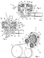
- FIG. 4 shows a tensioning arrangement 2 according to the invention in an installed state in a belt drive 32.
- the tensioning arrangement 2 is attached to a stationary component, in the present case on an assembly 33, the belt 34 is placed around all drive pulleys 35, 36, 37 and the tensioning rollers 5, 7 underneath Spring preload applied against the belt 34.
- the unit 33 can for example be a generator (alternator).
- the clamping arrangement 2 is attached to the unit 33 on the front side. This is done by means of the circumferentially distributed fastening flanges 46, which screws can be inserted and screwed to the housing of the unit.
- the clamping arrangement 2 is designed in such a way that - in the assembled state on the unit 33 - the pivot axes A4, A6 of the clamping arms 4, 6 are arranged within the outer diameter of the drive belt pulley 35.
- FIGS 5A to 5C together also as Figure 5 denoted, show a clamping arrangement 2 according to the invention in a further embodiment.
- the present clamping arrangement 2 corresponds in large parts to the embodiment according to FIG Figures 1A to 1C , whose description is referred to in abbreviated form with regard to the similarities.
- the same or modified details are provided with the same reference symbols as in the above figures.
- the tensioning arrangement 2 has only a single tensioning arm 4 with a corresponding tensioning roller 5.
- the first spring support is assigned to the single tensioning arm 4, as in the above embodiments.
- the second spring support is assigned to the base body 3 or is formed on it. The spring is arranged within the base body 3 and cannot be seen.
- the part 22, with which the clamping element 19 is clamped is formed in one piece with the carrier element 12.
- the carrier element 12 of the tensioning arm 4 has a bore with an internal thread into which the tensioning element 19 designed as a tensioning screw is screwed.
- the tensioning arm or support section 12 is in the present case designed as a solid part, for example as a light metal cast part.
- the Figure 5B shows the bearing 16 in a first possible setting position P1 in a coaxial arrangement to the carrier axis A12, a radial play sA being provided between the bore 21A of the bearing receiving part 17A and the sleeve section 22 arranged radially inward for this purpose.
- a radial play sB is provided between the bore 21B of the bearing receiving part 17B and the radially inner cylinder section 30.
- the radial play sA, sB can be between 0.1 mm and 0.3 mm on both sides.
- FIG 5C a second clamping position P2 is shown in which the Bearing receptacle 17 is pivoted relative to the carrier axis A12 or a parallel to the pivot axis A4 by a pivot angle ⁇ .
- the pivot angle ⁇ is preferably less than or equal to 1 ° relative to the axis A12 or A4.
- the clamping arrangement 2 corresponds to FIG Figures 5A to 5C of those according to the Figures 1A to 1C , the description of which is referred to here in abbreviated form.
- the Figure 6 shows schematically a clamping arrangement 2 according to the invention, which according to one of the embodiments according to FIGS Figures 1 to 4 as a two-arm clamp or according to Figure 5 can be designed as a one-arm clamp.
- a tension pulley (5) for an embodiment as a one-arm tensioner is shown with a solid line
- a second tension pulley (7) for an embodiment as a two-arm tensioner is shown with a dashed line.
- the geometrical relationships are explained above only with reference to the tensioning arm 4, it being understood that these can alternatively or additionally also apply to the second tensioning arm 6.
- the representation according to Figure 6 serves in particular to explain the geometric relationships and applies in particular to all of the embodiments described above. Identical or corresponding details are provided with the same reference symbols as in the above figures.
- the tensioning roller 5 can be pivoted with its axis of rotation A5 relative to the carrier axis A12 of the carrier element 12, the carrier axis A12 being able to be defined as parallel to the pivoting axis A4 of the tensioning arm through the bearing center point C of the tensioning roller bearing 16.
- the axis of rotation (A5) and the carrier axis A12 coincide.
- the axis of rotation and the support axis A12 span a pivot plane Ea.
- the pivot plane Ea can lie within an angular range ⁇ of up to ⁇ 180 ° around the carrier axis A12 relative to a tangent plane T in the axial view shown.
- the tangent plane T is in particular a plane perpendicular to the radius R, which extends from the Pivot axis A4 extends to the bearing center point C.
- the axis of rotation A5 is preferably pivotable relative to the tangent plane T at least within an angular range ⁇ of up to ⁇ 30 ° in the axial view shown.
- the exact alignment of the axis of rotation A5 is preferably based on the wrapping of the tensioning roller 5 by the belt 34, depending on the specific embodiment and installation situation.
- the pivoting plane Ea is preferably at least approximately in the bisecting plane between the two belt sections adjacent to the tensioning roller. In Figure 6 two possible positions of the swivel plane with Ea and Ea 'are shown by way of example, with any other angular position ( ⁇ ) being possible.
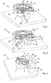
- Figure 7 shows an adjusting device 40 according to the invention for adjusting the clamping arrangement according to one of the Figures 1 to 4 .
- the setting device is used to set the pivot angle for a tensioning arrangement 2, in which only one tensioning roller can be set by means of a corresponding setting mechanism 11.
- the adjustment device 40 comprises a base plate 41, a holding device 42 for fixing the tensioning arrangement 2 on the base plate 41, and an alignment element 43 which is connected to the base plate 41 and has several alignment surfaces 44, 45 against which the tensioning roller 7 is clamped Belt tensioner 2 can be brought into contact.
- the device 40 enables the tensioning roller 7 to be set in a simple manner in the desired position relative to the carrier element 12 or to the base body 3 of the tensioning arrangement 2 and to be fixed in this position.
- the alignment element 43 of the setting device 40 is initially set once in the position required for the desired pivoting position of the tensioning roller 7 or provided in the desired form.
- the tensioning roller 7 is pivoted into the desired position.
- the arrangement is fixed in this position by subsequent tensioning of the tensioning roller 7 on the carrier element 12 by means of the tensioning element 19.
- the alignment element 43 has at least two alignment surfaces 44, 44 'arranged offset from one another in the circumferential direction of the tensioning roller 7. In this way, secure support is achieved in a plane perpendicular to the axis of rotation A5. Furthermore, the alignment element 43 has at least two alignment surfaces 44, 45 arranged offset from one another in the axial direction of the tensioning roller 7. In this way, secure support is achieved in a plane parallel to the axis of rotation A5.
- Figure 8 shows an adjusting device 40 according to the invention for adjusting a clamping arrangement 2 according to the invention according to one of the Figures 1 to 4 , in a second embodiment.
- the setting device 40 is used to set the pivot angle ⁇ for a tensioning arrangement 2, in which one or two tensioning rollers 5, 7 can be adjusted by means of a corresponding setting mechanism 11.
- the present setting device 40 largely corresponds to the embodiment according to FIG Figure 7 , whose description is referred to in abbreviated form with regard to the similarities. The same or modified details are provided with the same reference symbols as in FIG Figure 7 .
- a special feature of the present embodiment according to Figure 8 is that it has two alignment elements 43, 43 'which can be pivoted relative to one another about a pivot axis.
- the alignment elements 43, 43 'of the setting device 40 can be set individually or jointly into the position required for the respectively desired pivoting position of the tensioning rollers 5, 7, or can be provided in a configuration suitable for this.
- Figure 9 shows an adjusting device according to the invention for adjusting a clamping arrangement 2 according to the invention according to Figure 5 , which has only one clamping arm 4.
- Structure and mode of operation of the present setting device 40 according to FIG 9 largely correspond to the embodiment according to FIG Figure 7 , the description of which is referred to in abbreviated form. The same or modified details are provided with the same reference symbols as in FIG Figure 7 .
- the alignment element 43 of the adjustment device 40 according to FIG Figure 9 is the alignment element 43 of the adjustment device 40 according to FIG Figure 9 made correspondingly larger, so that the tensioning roller 5 can be brought into contact or the desired pivoting position against the alignment surfaces 44, 45 of the alignment element 43.
- tensioning arrangements 2 or the adjusting devices 40 are provided that the bearings 16 of the tensioning rollers 5, 7 and, accordingly, also the respective tensioning roller can be set to a desired position relative to the carrier element 12, 13.
- a defined inclination of the tensioning roller 5, 7 relative to the carrier 12, 13 or base body 3, which can also be zero, can be achieved in a simple and inexpensive manner.
Landscapes
- Engineering & Computer Science (AREA)
- General Engineering & Computer Science (AREA)
- Mechanical Engineering (AREA)
- Devices For Conveying Motion By Means Of Endless Flexible Members (AREA)
- Support Of The Bearing (AREA)
Applications Claiming Priority (1)
| Application Number | Priority Date | Filing Date | Title |
|---|---|---|---|
| DE102019115628.9A DE102019115628B3 (de) | 2019-06-07 | 2019-06-07 | Spannanordnung mit Spannrolle und Vorrichtung zum Einstellen einer Spannanordnung |
Publications (2)
| Publication Number | Publication Date |
|---|---|
| EP3748193A2 true EP3748193A2 (fr) | 2020-12-09 |
| EP3748193A3 EP3748193A3 (fr) | 2021-02-17 |
Family
ID=69725296
Family Applications (1)
| Application Number | Title | Priority Date | Filing Date |
|---|---|---|---|
| EP20176190.5A Withdrawn EP3748193A3 (fr) | 2019-06-07 | 2020-05-22 | Agencement de serrage pourvu de rouleau de serrage et dispositif de réglage d'un agencement de serrage |
Country Status (5)
| Country | Link |
|---|---|
| US (1) | US20200386302A1 (fr) |
| EP (1) | EP3748193A3 (fr) |
| JP (1) | JP2020200947A (fr) |
| CN (1) | CN112049905A (fr) |
| DE (1) | DE102019115628B3 (fr) |
Families Citing this family (1)
| Publication number | Priority date | Publication date | Assignee | Title |
|---|---|---|---|---|
| LU503149B1 (de) * | 2022-12-07 | 2024-06-07 | Saurer Spinning Solutions Gmbh & Co Kg | System zur Spannung eines Antriebsriemens eines Streckwerks mit einem Streckwerk und einer Riemenspannzange |
Citations (3)
| Publication number | Priority date | Publication date | Assignee | Title |
|---|---|---|---|---|
| DE102011088213A1 (de) | 2011-12-12 | 2013-06-13 | Schaeffler Technologies AG & Co. KG | Spannanordnung für einen Zugmitteltrieb |
| DE102015111809A1 (de) | 2015-07-21 | 2017-01-26 | Muhr Und Bender Kg | Spannvorrichtung |
| WO2018178143A1 (fr) | 2017-03-31 | 2018-10-04 | Muhr Und Bender Kg | Dispositif tendeur avec mécanisme de positionnement et procédé de réglage du couple du dispositif tendeur |
Family Cites Families (3)
| Publication number | Priority date | Publication date | Assignee | Title |
|---|---|---|---|---|
| DE102009005116A1 (de) * | 2009-01-19 | 2010-07-22 | Schaeffler Technologies Gmbh & Co. Kg | Lageranordnung für eine Laufrolle sowie Spanneinrichtung mit einer derartigen Lageranordnung |
| DE102016207774A1 (de) * | 2016-05-04 | 2017-11-09 | Schaeffler Technologies AG & Co. KG | Kippbewegliche Lagerung mit einer Rolle mit Wälzlager und einem Lagerzapfen sowie Endloszugmitteltrieb |
| DE102017124783B3 (de) * | 2017-10-24 | 2019-03-21 | Muhr Und Bender Kg | Spannvorrichtung |
-
2019
- 2019-06-07 DE DE102019115628.9A patent/DE102019115628B3/de active Active
-
2020
- 2020-05-22 EP EP20176190.5A patent/EP3748193A3/fr not_active Withdrawn
- 2020-05-27 CN CN202010462254.0A patent/CN112049905A/zh active Pending
- 2020-06-01 US US16/888,924 patent/US20200386302A1/en not_active Abandoned
- 2020-06-05 JP JP2020098204A patent/JP2020200947A/ja active Pending
Patent Citations (3)
| Publication number | Priority date | Publication date | Assignee | Title |
|---|---|---|---|---|
| DE102011088213A1 (de) | 2011-12-12 | 2013-06-13 | Schaeffler Technologies AG & Co. KG | Spannanordnung für einen Zugmitteltrieb |
| DE102015111809A1 (de) | 2015-07-21 | 2017-01-26 | Muhr Und Bender Kg | Spannvorrichtung |
| WO2018178143A1 (fr) | 2017-03-31 | 2018-10-04 | Muhr Und Bender Kg | Dispositif tendeur avec mécanisme de positionnement et procédé de réglage du couple du dispositif tendeur |
Also Published As
| Publication number | Publication date |
|---|---|
| JP2020200947A (ja) | 2020-12-17 |
| DE102019115628B3 (de) | 2020-03-26 |
| US20200386302A1 (en) | 2020-12-10 |
| CN112049905A (zh) | 2020-12-08 |
| EP3748193A3 (fr) | 2021-02-17 |
Similar Documents
| Publication | Publication Date | Title |
|---|---|---|
| EP3601845B1 (fr) | Dispositif tendeur avec mécanisme de positionnement et procédé de réglage du couple du dispositif tendeur | |
| DE69703497T2 (de) | Riemenspannvorrichtung, insbesondere für kraftfahrzeuge | |
| EP3023670B1 (fr) | Dispositif de tension de courroie | |
| DE102013102562B4 (de) | Verwendung einer Feder in einer Riemenspannvorrichtung, Riemenspannvorrichtung und Aggregatanordnung | |
| DE60206392T2 (de) | Riemenspanner mit montagestift | |
| DE3512376C2 (fr) | ||
| DE69610811T2 (de) | Dämpfungsmechanismus für einen Riemenspanner | |
| EP2612053B1 (fr) | Poulie de tension à excentrique | |
| EP3431815B1 (fr) | Dispositif de tension de courroie | |
| EP3121484B1 (fr) | Dispositif de serrage | |
| DE102017124783B3 (de) | Spannvorrichtung | |
| DE19807822B4 (de) | Schwenklager | |
| EP3885609B1 (fr) | Dispositif de tension de courroie | |
| EP2957793A2 (fr) | Dispositif de tension de courroie | |
| DE10347685B4 (de) | Motorriemenantrieb mit sich selbstausrichtender Riemenscheibe | |
| DE102006047006A1 (de) | Kraftübertragungseinrichtung | |
| EP0509313A1 (fr) | Dispositif tendeur de courroie | |
| DE102019115628B3 (de) | Spannanordnung mit Spannrolle und Vorrichtung zum Einstellen einer Spannanordnung | |
| EP3943778B1 (fr) | Dispositif de tension de courroie et entraînement de courroie doté d'un tel dispositif de tension de courroie | |
| DE3546901C2 (de) | Automatische Riemenspannvorrichtung | |
| DE10133157A1 (de) | Spannvorrichtung | |
| DE102017114039B4 (de) | Spannrollenanordnung | |
| DE102021113278A1 (de) | Kettenführung | |
| EP1781913A1 (fr) | Logement a point d'appui d'un organe | |
| DE102009005116A1 (de) | Lageranordnung für eine Laufrolle sowie Spanneinrichtung mit einer derartigen Lageranordnung |
Legal Events
| Date | Code | Title | Description |
|---|---|---|---|
| PUAI | Public reference made under article 153(3) epc to a published international application that has entered the european phase |
Free format text: ORIGINAL CODE: 0009012 |
|
| STAA | Information on the status of an ep patent application or granted ep patent |
Free format text: STATUS: THE APPLICATION HAS BEEN PUBLISHED |
|
| AK | Designated contracting states |
Kind code of ref document: A2 Designated state(s): AL AT BE BG CH CY CZ DE DK EE ES FI FR GB GR HR HU IE IS IT LI LT LU LV MC MK MT NL NO PL PT RO RS SE SI SK SM TR |
|
| AX | Request for extension of the european patent |
Extension state: BA ME |
|
| PUAL | Search report despatched |
Free format text: ORIGINAL CODE: 0009013 |
|
| AK | Designated contracting states |
Kind code of ref document: A3 Designated state(s): AL AT BE BG CH CY CZ DE DK EE ES FI FR GB GR HR HU IE IS IT LI LT LU LV MC MK MT NL NO PL PT RO RS SE SI SK SM TR |
|
| AX | Request for extension of the european patent |
Extension state: BA ME |
|
| RIC1 | Information provided on ipc code assigned before grant |
Ipc: F16H 7/08 20060101AFI20210112BHEP Ipc: F16H 7/12 20060101ALI20210112BHEP |
|
| STAA | Information on the status of an ep patent application or granted ep patent |
Free format text: STATUS: THE APPLICATION IS DEEMED TO BE WITHDRAWN |
|
| 18D | Application deemed to be withdrawn |
Effective date: 20210818 |