EP3748208A1 - Obus de valve - Google Patents
Obus de valve Download PDFInfo
- Publication number
- EP3748208A1 EP3748208A1 EP18911860.7A EP18911860A EP3748208A1 EP 3748208 A1 EP3748208 A1 EP 3748208A1 EP 18911860 A EP18911860 A EP 18911860A EP 3748208 A1 EP3748208 A1 EP 3748208A1
- Authority
- EP
- European Patent Office
- Prior art keywords
- barrel
- valve core
- flange
- head
- packing
- Prior art date
- Legal status (The legal status is an assumption and is not a legal conclusion. Google has not performed a legal analysis and makes no representation as to the accuracy of the status listed.)
- Withdrawn
Links
Images



Classifications
-
- F—MECHANICAL ENGINEERING; LIGHTING; HEATING; WEAPONS; BLASTING
- F16—ENGINEERING ELEMENTS AND UNITS; GENERAL MEASURES FOR PRODUCING AND MAINTAINING EFFECTIVE FUNCTIONING OF MACHINES OR INSTALLATIONS; THERMAL INSULATION IN GENERAL
- F16K—VALVES; TAPS; COCKS; ACTUATING-FLOATS; DEVICES FOR VENTING OR AERATING
- F16K15/00—Check valves
- F16K15/20—Check valves specially designed for inflatable bodies, e.g. tyres
-
- B—PERFORMING OPERATIONS; TRANSPORTING
- B60—VEHICLES IN GENERAL
- B60C—VEHICLE TYRES; TYRE INFLATION; TYRE CHANGING; CONNECTING VALVES TO INFLATABLE ELASTIC BODIES IN GENERAL; DEVICES OR ARRANGEMENTS RELATED TO TYRES
- B60C29/00—Arrangements of tyre-inflating valves to tyres or rims; Accessories for tyre-inflating valves, not otherwise provided for
-
- B—PERFORMING OPERATIONS; TRANSPORTING
- B60—VEHICLES IN GENERAL
- B60C—VEHICLE TYRES; TYRE INFLATION; TYRE CHANGING; CONNECTING VALVES TO INFLATABLE ELASTIC BODIES IN GENERAL; DEVICES OR ARRANGEMENTS RELATED TO TYRES
- B60C29/00—Arrangements of tyre-inflating valves to tyres or rims; Accessories for tyre-inflating valves, not otherwise provided for
- B60C29/002—Arrangements of tyre-inflating valves to tyres or rims; Accessories for tyre-inflating valves, not otherwise provided for characterised by particular features of the valve core
-
- F—MECHANICAL ENGINEERING; LIGHTING; HEATING; WEAPONS; BLASTING
- F16—ENGINEERING ELEMENTS AND UNITS; GENERAL MEASURES FOR PRODUCING AND MAINTAINING EFFECTIVE FUNCTIONING OF MACHINES OR INSTALLATIONS; THERMAL INSULATION IN GENERAL
- F16K—VALVES; TAPS; COCKS; ACTUATING-FLOATS; DEVICES FOR VENTING OR AERATING
- F16K25/00—Details relating to contact between valve members and seats
- F16K25/005—Particular materials for seats or closure elements
-
- F—MECHANICAL ENGINEERING; LIGHTING; HEATING; WEAPONS; BLASTING
- F25—REFRIGERATION OR COOLING; COMBINED HEATING AND REFRIGERATION SYSTEMS; HEAT PUMP SYSTEMS; MANUFACTURE OR STORAGE OF ICE; LIQUEFACTION SOLIDIFICATION OF GASES
- F25B—REFRIGERATION MACHINES, PLANTS OR SYSTEMS; COMBINED HEATING AND REFRIGERATION SYSTEMS; HEAT PUMP SYSTEMS
- F25B45/00—Arrangements for charging or discharging refrigerant
-
- B—PERFORMING OPERATIONS; TRANSPORTING
- B60—VEHICLES IN GENERAL
- B60C—VEHICLE TYRES; TYRE INFLATION; TYRE CHANGING; CONNECTING VALVES TO INFLATABLE ELASTIC BODIES IN GENERAL; DEVICES OR ARRANGEMENTS RELATED TO TYRES
- B60C29/00—Arrangements of tyre-inflating valves to tyres or rims; Accessories for tyre-inflating valves, not otherwise provided for
- B60C29/005—Arrangements of tyre-inflating valves to tyres or rims; Accessories for tyre-inflating valves, not otherwise provided for characterised by particular features of the valve stem
-
- B—PERFORMING OPERATIONS; TRANSPORTING
- B60—VEHICLES IN GENERAL
- B60C—VEHICLE TYRES; TYRE INFLATION; TYRE CHANGING; CONNECTING VALVES TO INFLATABLE ELASTIC BODIES IN GENERAL; DEVICES OR ARRANGEMENTS RELATED TO TYRES
- B60C29/00—Arrangements of tyre-inflating valves to tyres or rims; Accessories for tyre-inflating valves, not otherwise provided for
- B60C29/06—Accessories for tyre-inflating valves, e.g. housings, guards, covers for valve caps, locks, not otherwise provided for
-
- F—MECHANICAL ENGINEERING; LIGHTING; HEATING; WEAPONS; BLASTING
- F16—ENGINEERING ELEMENTS AND UNITS; GENERAL MEASURES FOR PRODUCING AND MAINTAINING EFFECTIVE FUNCTIONING OF MACHINES OR INSTALLATIONS; THERMAL INSULATION IN GENERAL
- F16L—PIPES; JOINTS OR FITTINGS FOR PIPES; SUPPORTS FOR PIPES, CABLES OR PROTECTIVE TUBING; MEANS FOR THERMAL INSULATION IN GENERAL
- F16L37/00—Couplings of the quick-acting type
- F16L37/28—Couplings of the quick-acting type with fluid cut-off means
- F16L37/38—Couplings of the quick-acting type with fluid cut-off means with fluid cut-off means in only one of two pipe-end fittings
- F16L37/40—Couplings of the quick-acting type with fluid cut-off means with fluid cut-off means in only one of two pipe-end fittings with a lift valve being opened automatically when the coupling is applied
-
- Y—GENERAL TAGGING OF NEW TECHNOLOGICAL DEVELOPMENTS; GENERAL TAGGING OF CROSS-SECTIONAL TECHNOLOGIES SPANNING OVER SEVERAL SECTIONS OF THE IPC; TECHNICAL SUBJECTS COVERED BY FORMER USPC CROSS-REFERENCE ART COLLECTIONS [XRACs] AND DIGESTS
- Y10—TECHNICAL SUBJECTS COVERED BY FORMER USPC
- Y10T—TECHNICAL SUBJECTS COVERED BY FORMER US CLASSIFICATION
- Y10T137/00—Fluid handling
- Y10T137/3584—Inflatable article [e.g., tire filling chuck and/or stem]
- Y10T137/3786—Removable valve head and seat unit [valve insides]
-
- Y—GENERAL TAGGING OF NEW TECHNOLOGICAL DEVELOPMENTS; GENERAL TAGGING OF CROSS-SECTIONAL TECHNOLOGIES SPANNING OVER SEVERAL SECTIONS OF THE IPC; TECHNICAL SUBJECTS COVERED BY FORMER USPC CROSS-REFERENCE ART COLLECTIONS [XRACs] AND DIGESTS
- Y10—TECHNICAL SUBJECTS COVERED BY FORMER USPC
- Y10T—TECHNICAL SUBJECTS COVERED BY FORMER US CLASSIFICATION
- Y10T137/00—Fluid handling
- Y10T137/7504—Removable valve head and seat unit
- Y10T137/7613—Threaded into valve casing
Definitions
- the present invention relates to a valve core.
- Patent Document 1 discloses a valve core in which a barrel packing fitted to the outer surface is pressed by a flange part against the inner surface of a valve stem.
- Patent Document 1 Japanese Unexamined Patent Application Publication No. 2004-360832 ( FIG. 3 )
- part of the valve core such as the flange part may deform. It is desired to suppress such deformation.
- the invention according to claim 1 is a valve core including: a barrel part that is cylindrical; a barrel packing that surrounds an outer lateral surface of the barrel part; a flange part that abuts on the barrel packing from above; and a head part that includes a male screw part at its outer lateral surface and that rotates relative to the barrel part. A lower surface of the head part abuts on the flange part from above.
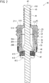
- FIG. 1 illustrates a valve stem 50 that houses a valve core 10 according to the present embodiment.
- the valve stem 50 is cylindrical and extends from a tire (not shown).
- the inside of the valve stem 50 serves as a core mount hole 55 that communicates with the inner space of the tire.
- a female screw part 52 is formed at the position near the opening of the core mount hole 55.
- a diameter-reduced part 53 having its diameter gradually reduced as becoming farther from the female screw part 52 is provided.
- a male screw part 54 for screwing and fixing to a not-shown cap is formed on the outer circumferential surface of the valve stem 50.
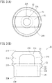
- the valve core 10 Into the core mount hole 55, the valve core 10 according to the present embodiment is screw-fixed. As shown in FIG. 2 , the valve core 10 includes a head part 20, a barrel part 30, and a movable shaft 40 inserted into the head part 20 and the barrel part 30. Note that, in the following, the side where the head part 20 is disposed relative to the barrel part 30 is referred to as the upper side, and the side opposite thereto is referred to as the lower side.
- the movable shaft 40 includes a spring stop part 41A that engages with a compression coil spring 45 at the upper end of a shaft part 41 that penetrates through the central parts of the head part 20 and the barrel part 30, and further includes a valve body 42 at the midway position.
- the valve body 42 is formed of a tapered part 41B having its diameter gradually increased from the shaft part 41, a column part 41C greater in diameter than the tapered part 41B and disposed as being spaced apart from the diameter-increased side end (the lower end) of the tapered part 41B, and a seal part 41D interposed between the tapered part 41B and the column part 41C.
- the movable shaft 40 according to the present embodiment is formed of a conductor such as a brass, and the seal part 41D is formed of an elastic member such as rubber or elastomer.
- the head part 20 includes, at its center, a through hole 20A into which the movable shaft 40 and the upper end of the barrel part 30 are inserted.
- the head part 20 is further provided with, at its outer lateral surface, a male screw part 23 that screws with the valve stem 50.
- the head part 20 includes: a disc-like base part 22; and a gate part 21 that has a gate structure formed of a pair of struts 21S, 21S respectively standing from two positions separated from each other by 180 degrees at the upper end surface of the base part 22 and a bridge part 21H provided across the struts 21S, 21S.
- the head part 20 is formed of an insulator such as ceramic or resin.
- a compression coil spring 45 is provided between the spring stop part 41A of the movable shaft 40 and the head part 20 .
- the shaft part 41 is inserted into the compression coil spring 45 compressed between the spring stop part 41A and the upper surface 21J of the gate part 21.
- the barrel part 30 is cylindrical and provided with a through hole 30A at its center into which the movable shaft 40 is inserted.
- the barrel part 30 includes, at its midway position, a flange part 35 which projects outward.
- the outer diameter of an insert part 31 formed upper than the flange part 35 is smaller than the through hole 20A of the head part 20, and the insert part 31 is inserted into the through hole 20A of the head part 20.
- the outer diameter of a base part 32 formed lower than the flange part 35 is greater than the outer diameter of the insert part 31.
- a tapered part 32T having its inner diameter gradually reduced upward is formed.
- a seal part 42D of the valve body 42 of the movable shaft 40 biased upward by the compression coil spring 45 fits.
- the barrel part 30 according to the present embodiment is formed of an insulator such as ceramic or resin.
- the barrel part 30 is provided with a barrel packing 48 that surrounds the outer lateral surface 30M of the barrel part 30.
- the barrel packing 48 is formed of, for example, elastomer. As shown in FIG. 4 , the barrel packing 48 has its upper surface 48J abutted on a lower surface 35K of the flange part 35.
- the barrel packing 48 has the diameter of the outer lateral surface reduced from the intermediate position in the top-bottom direction to the lower end. Note that, the thickness of the barrel packing 48 is made to be substantially identical to the projecting amount of the lower surface of the flange part 35.
- a lower surface 20M of the head part 20 is configured to abuttable on the flange part 35.
- the base part 22 of the head part 20 includes a screwing sleeve part 24 provided with a male screw part 23 at its outer lateral surface and an extending part 25 extending downward from the screwing sleeve part 24.
- a lower surface 25M of the extending part 25 abuts on an upper surface 35J of the flange part 35.
- the lower surface 20M of the head part 20 is disposed at the position overlapping the barrel packing 48 in the top-bottom direction.
- the lower surface 20M of the head part 20 has its outer edge part 25G disposed at the central position in the radial direction of the barrel packing 48, and has its inner edge part 25N disposed at the position overlapping the base part 32 of the barrel part 30. That is, the lower surface 20M of the head part 20 abuts on the flange part 35 across a root part 35T of the flange part 35 on the lower surface 35K side in the radial direction.
- the valve core 10 is mounted on the core mount hole 55 in the following manner. That is, the valve core 10 is rotated in a state of being inserted into the core mount hole 55 from the barrel part 30 side. Then, the male screw part 23 formed at the head part of the valve core 10 screws with the female screw part 52 of the core mount hole 55, and the valve core 10 shifts to the depth side of the core mount hole 55. Then, as shown in FIG. 1 , the barrel packing 48 that covers the barrel part 30 abuts on the diameter-reduced part 53 of the core mount hole 55, thereby to stop the rotation of the head part 20.
- the lower surface 20M of the head part 20 abuts on the flange part 35 across the root part 35T on the lower surface 35K side of the flange part 35 in the radial direction. That is, the valve core 10 is structured to back up the portion above the portion where stress tends to concentrate. This contributes to suppressing deformation of the flange part 35.
- the movable shaft 40 is formed of a conductor and the head part 20 and the barrel part 30 are formed of an insulator. Therefore, the movable shaft 40 can be used as a current path.
Landscapes
- Engineering & Computer Science (AREA)
- General Engineering & Computer Science (AREA)
- Mechanical Engineering (AREA)
- Physics & Mathematics (AREA)
- Thermal Sciences (AREA)
- Lift Valve (AREA)
- Check Valves (AREA)
- Bolts, Nuts, And Washers (AREA)
- Gasket Seals (AREA)
Applications Claiming Priority (1)
| Application Number | Priority Date | Filing Date | Title |
|---|---|---|---|
| PCT/JP2018/013432 WO2019186956A1 (fr) | 2018-03-29 | 2018-03-29 | Obus de valve |
Publications (2)
| Publication Number | Publication Date |
|---|---|
| EP3748208A1 true EP3748208A1 (fr) | 2020-12-09 |
| EP3748208A4 EP3748208A4 (fr) | 2021-01-20 |
Family
ID=68059619
Family Applications (1)
| Application Number | Title | Priority Date | Filing Date |
|---|---|---|---|
| EP18911860.7A Withdrawn EP3748208A4 (fr) | 2018-03-29 | 2018-03-29 | Obus de valve |
Country Status (6)
| Country | Link |
|---|---|
| US (1) | US11313483B2 (fr) |
| EP (1) | EP3748208A4 (fr) |
| JP (1) | JP6976417B2 (fr) |
| KR (1) | KR102461548B1 (fr) |
| CN (1) | CN111836987B (fr) |
| WO (1) | WO2019186956A1 (fr) |
Cited By (2)
| Publication number | Priority date | Publication date | Assignee | Title |
|---|---|---|---|---|
| US11493139B1 (en) | 2021-08-20 | 2022-11-08 | Santa Cruz Bicycles, LLC | Inflation valve for tubeless tires |
| US11904644B2 (en) | 2019-04-17 | 2024-02-20 | Santa Cruz Bicycles, LLC | Inflation system for tubeless tires |
Families Citing this family (8)
| Publication number | Priority date | Publication date | Assignee | Title |
|---|---|---|---|---|
| WO2017027716A1 (fr) * | 2015-08-11 | 2017-02-16 | Trane International Inc. | Récupération et réhabilitation de réfrigérant |
| EP4155590A1 (fr) * | 2019-03-26 | 2023-03-29 | Pacific Industrial Co., Ltd. | Soupape |
| EP3851718A4 (fr) * | 2019-09-27 | 2021-09-29 | Pacific Industrial Co., Ltd. | Obus de valve |
| US11719351B2 (en) | 2020-01-27 | 2023-08-08 | John Quintana | Pneumatic valve system and methods of using the same |
| CN114233793B (zh) * | 2021-12-31 | 2023-12-01 | 高密同创气门芯有限公司 | 一种氮气弹簧气门芯及氮气弹簧 |
| CN114812022A (zh) * | 2022-04-21 | 2022-07-29 | 应雪汽车科技(常熟)有限公司 | 一种二氧化碳为制冷剂的空调充注阀 |
| WO2024196787A1 (fr) * | 2023-03-17 | 2024-09-26 | Clik Corporation | Valve pneumatique, tête de pompe et accessoires pour une valve pneumatique |
| EP4600053A1 (fr) * | 2024-02-06 | 2025-08-13 | Clik Corporation | Système de soupape pneumatique |
Family Cites Families (30)
| Publication number | Priority date | Publication date | Assignee | Title |
|---|---|---|---|---|
| US854182A (en) * | 1905-09-05 | 1907-05-21 | Maximilian Charles Schweinert | Tire or other valve. |
| US1050491A (en) * | 1906-05-26 | 1913-01-14 | Schraders Son Inc | Tire-valve. |
| US1171147A (en) * | 1913-02-08 | 1916-02-08 | Maximilian Charles Schweinert | Tire-valve. |
| GB157183A (en) * | 1915-08-27 | 1921-05-05 | Schraders Son Inc | Pneumatic valves |
| US1255411A (en) * | 1916-01-06 | 1918-02-05 | Firestone Tire & Rubber Co | Air-valve for pneumatic tires. |
| US1338245A (en) * | 1916-03-25 | 1920-04-27 | Schraders Son Inc | Tire-valve or the like |
| US1453721A (en) * | 1918-01-03 | 1923-05-01 | Conrad Hubert | Tire valve |
| US1426350A (en) * | 1918-06-20 | 1922-08-22 | Adelbert E Bronson | Valve for pneumatic tires |
| US1593313A (en) * | 1923-11-19 | 1926-07-20 | Lloyd B Solemink | Tire valve |
| US2075167A (en) * | 1931-07-01 | 1937-03-30 | Bridgeport Brass Co | Pneumatic valve inside construction |
| US2068266A (en) * | 1932-03-23 | 1937-01-19 | Schraders Son Inc | Tire valve |
| US1991974A (en) * | 1932-05-28 | 1935-02-19 | Bridgeport Brass Co | Springless tire valve inside construction |
| US2228984A (en) * | 1938-05-07 | 1941-01-14 | Bridgeport Brass Co | Pneumatic tire valve |
| US2272634A (en) * | 1939-05-06 | 1942-02-10 | Dill Mfg Co | Valve insides |
| US2240096A (en) * | 1940-05-23 | 1941-04-29 | Jenkins Bros | Valve stem of the capless type |
| US2758608A (en) | 1952-08-29 | 1956-08-14 | Sutcliffe John William | Tire stem inflation valve |
| US2862515A (en) * | 1956-02-21 | 1958-12-02 | Scovill Manufacturing Co | Check valve |
| DE1976938U (de) * | 1967-09-30 | 1968-01-11 | Alligator Ventilfabrik Ges Mit | Ventileinsatz, insbesondere fuer luftreifenventile. |
| JPS5335281Y2 (fr) | 1976-01-21 | 1978-08-29 | ||
| US4462449A (en) * | 1982-02-02 | 1984-07-31 | Zabel Jr John H | Valve core for pneumatic tires |
| JPS59144268U (ja) | 1983-03-17 | 1984-09-27 | 太平洋工業株式会社 | タイヤバルブ |
| US6966331B2 (en) * | 2002-04-16 | 2005-11-22 | Simmons Jerry C | Valve stem adaptor |
| JP4340477B2 (ja) | 2003-06-05 | 2009-10-07 | 株式会社ブリヂストン | 安全タイヤ用バルブ、カプラー付き充填アダプター、放圧アダプター、及び放圧方法 |
| JP4180451B2 (ja) | 2003-06-26 | 2008-11-12 | 太平洋工業株式会社 | バルブコア |
| JP4478473B2 (ja) | 2003-06-26 | 2010-06-09 | 太平洋工業株式会社 | バルブコア |
| FR2896293B1 (fr) * | 2006-01-17 | 2010-08-13 | Schrader Sas | Mecanisme d'ouverture ou de fermeture d'une valve a deux positions de fermeture |
| JP4714631B2 (ja) * | 2006-04-20 | 2011-06-29 | 太平洋工業株式会社 | バルブコア |
| CN201318484Y (zh) * | 2008-11-14 | 2009-09-30 | 王平 | 新型气门芯 |
| CN103727275A (zh) * | 2013-11-28 | 2014-04-16 | 高密市威达环保设备有限公司 | 新型气门芯装置 |
| JP6636344B2 (ja) | 2016-01-22 | 2020-01-29 | 太平洋工業株式会社 | バルブコア |
-
2018
- 2018-03-29 KR KR1020207024593A patent/KR102461548B1/ko active Active
- 2018-03-29 JP JP2020508752A patent/JP6976417B2/ja active Active
- 2018-03-29 CN CN201880090595.0A patent/CN111836987B/zh active Active
- 2018-03-29 WO PCT/JP2018/013432 patent/WO2019186956A1/fr not_active Ceased
- 2018-03-29 US US16/976,105 patent/US11313483B2/en active Active
- 2018-03-29 EP EP18911860.7A patent/EP3748208A4/fr not_active Withdrawn
Cited By (3)
| Publication number | Priority date | Publication date | Assignee | Title |
|---|---|---|---|---|
| US11904644B2 (en) | 2019-04-17 | 2024-02-20 | Santa Cruz Bicycles, LLC | Inflation system for tubeless tires |
| US11493139B1 (en) | 2021-08-20 | 2022-11-08 | Santa Cruz Bicycles, LLC | Inflation valve for tubeless tires |
| EP4137334A1 (fr) * | 2021-08-20 | 2023-02-22 | Santa Cruz Bicycles, LLC | Soupape de gonflage de pneus sans chambre à air |
Also Published As
| Publication number | Publication date |
|---|---|
| JPWO2019186956A1 (ja) | 2021-04-22 |
| US11313483B2 (en) | 2022-04-26 |
| EP3748208A4 (fr) | 2021-01-20 |
| KR20200111773A (ko) | 2020-09-29 |
| US20200408314A1 (en) | 2020-12-31 |
| CN111836987B (zh) | 2022-06-28 |
| CN111836987A (zh) | 2020-10-27 |
| JP6976417B2 (ja) | 2021-12-08 |
| KR102461548B1 (ko) | 2022-11-01 |
| WO2019186956A1 (fr) | 2019-10-03 |
Similar Documents
| Publication | Publication Date | Title |
|---|---|---|
| EP3748208A1 (fr) | Obus de valve | |
| US11355881B2 (en) | Electrical connector housing, electrical connector and electrical connector assembly | |
| TWI681176B (zh) | 力量感測器單元 | |
| US10240625B2 (en) | Assembly unit | |
| US10125803B2 (en) | Fixing device for lower level member and fluid control apparatus provided with the same | |
| US10181669B2 (en) | Large-slippage connector | |
| US9568388B2 (en) | Small form factor pressure sensor | |
| US11276524B2 (en) | Ignition coil | |
| JP6976418B2 (ja) | バルブコア及びタイヤバルブ | |
| US9709454B2 (en) | Non-resonant knock sensor | |
| CN109732528A (zh) | 一种轴用钢丝挡圈安装装置 | |
| US20160204525A1 (en) | Pressing Element, Electrical/Electronic Component | |
| JP6826845B2 (ja) | シール材圧入装着用治具 | |
| CN106151244A (zh) | 弹性挡圈及弹性挡圈安装装置 | |
| JP2020187903A (ja) | スパークプラグの製造方法 | |
| CN109003844B (zh) | 电触头组件 | |
| US10822016B2 (en) | Shock-absorbing stopper | |
| US10337582B2 (en) | Damper and method for manufacturing damper | |
| EP3098913A1 (fr) | Bougie d'allumage | |
| KR101410458B1 (ko) | 래치조립체 | |
| JP2012246995A (ja) | ボールねじ | |
| CN109421018B (zh) | 一种油封装配工装 | |
| CN113013010B (zh) | 波纹管结构、调整垂直度的方法及其等离子体处理装置 | |
| CN213106646U (zh) | 一种玻璃升降器主轴卡簧简易安装工装 | |
| CN214838209U (zh) | 一种丝杠定位结构及丝杠驱动装置 |
Legal Events
| Date | Code | Title | Description |
|---|---|---|---|
| STAA | Information on the status of an ep patent application or granted ep patent |
Free format text: STATUS: THE INTERNATIONAL PUBLICATION HAS BEEN MADE |
|
| PUAI | Public reference made under article 153(3) epc to a published international application that has entered the european phase |
Free format text: ORIGINAL CODE: 0009012 |
|
| STAA | Information on the status of an ep patent application or granted ep patent |
Free format text: STATUS: REQUEST FOR EXAMINATION WAS MADE |
|
| 17P | Request for examination filed |
Effective date: 20200903 |
|
| AK | Designated contracting states |
Kind code of ref document: A1 Designated state(s): AL AT BE BG CH CY CZ DE DK EE ES FI FR GB GR HR HU IE IS IT LI LT LU LV MC MK MT NL NO PL PT RO RS SE SI SK SM TR |
|
| AX | Request for extension of the european patent |
Extension state: BA ME |
|
| A4 | Supplementary search report drawn up and despatched |
Effective date: 20201217 |
|
| RIC1 | Information provided on ipc code assigned before grant |
Ipc: F25B 45/00 20060101ALI20201211BHEP Ipc: F16K 15/20 20060101AFI20201211BHEP Ipc: B60C 29/00 20060101ALI20201211BHEP Ipc: F16K 15/06 20060101ALI20201211BHEP |
|
| DAV | Request for validation of the european patent (deleted) | ||
| DAX | Request for extension of the european patent (deleted) | ||
| STAA | Information on the status of an ep patent application or granted ep patent |
Free format text: STATUS: THE APPLICATION IS DEEMED TO BE WITHDRAWN |
|
| 18D | Application deemed to be withdrawn |
Effective date: 20210730 |