EP3748219A1 - Appareil pour une installation de gestion de gaz - Google Patents
Appareil pour une installation de gestion de gaz Download PDFInfo
- Publication number
- EP3748219A1 EP3748219A1 EP20177982.4A EP20177982A EP3748219A1 EP 3748219 A1 EP3748219 A1 EP 3748219A1 EP 20177982 A EP20177982 A EP 20177982A EP 3748219 A1 EP3748219 A1 EP 3748219A1
- Authority
- EP
- European Patent Office
- Prior art keywords
- network
- gas
- pressure
- inlet
- module
- Prior art date
- Legal status (The legal status is an assumption and is not a legal conclusion. Google has not performed a legal analysis and makes no representation as to the accuracy of the status listed.)
- Granted
Links
Images




Classifications
-
- F—MECHANICAL ENGINEERING; LIGHTING; HEATING; WEAPONS; BLASTING
- F17—STORING OR DISTRIBUTING GASES OR LIQUIDS
- F17D—PIPE-LINE SYSTEMS; PIPE-LINES
- F17D1/00—Pipe-line systems
- F17D1/02—Pipe-line systems for gases or vapours
- F17D1/04—Pipe-line systems for gases or vapours for distribution of gas
-
- F—MECHANICAL ENGINEERING; LIGHTING; HEATING; WEAPONS; BLASTING
- F17—STORING OR DISTRIBUTING GASES OR LIQUIDS
- F17D—PIPE-LINE SYSTEMS; PIPE-LINES
- F17D1/00—Pipe-line systems
- F17D1/02—Pipe-line systems for gases or vapours
- F17D1/065—Arrangements for producing propulsion of gases or vapours
- F17D1/07—Arrangements for producing propulsion of gases or vapours by compression
Definitions
- the present invention relates to an apparatus for a system for the management of gases produced in a decentralized way, in particular renewable gases.
- gases produced in a decentralized way are known, for example, biomethane, syngas, hydrogen, methanation of hydrogen.
- biomethane is a gas that mainly contains methane (CH 4 ) and that is produced from a renewable source.
- biomethane derives from biogas which is subjected to an upgrading or purification process (by removing carbon dioxide, dehydration, desulfurization, removing gaseous ammonia, dust or other impurities) until biomethane reaches substantially the quality similar to that of natural gas.
- an upgrading or purification process by removing carbon dioxide, dehydration, desulfurization, removing gaseous ammonia, dust or other impurities
- the biomethane thus obtained contains a quantity of methane ⁇ about 95% and is chemically very similar to natural gas.
- the biomethane production plant can also include an appropriate compression and/or odorization of the biomethane obtained, which can thus be introduced into the gas transmission or distribution network to be used substantially in the same applications and destinations as for natural gas (for example for heating and cooking in domestic or industrial users).
- DE102009038128 describes a method of injection of gas from a medium pressure distribution network to a higher pressure transport network. This method involves the use of a compressor controlled on the basis of pressure measurements made upstream of the compressor itself.
- the solution of DE102009038128 also provides a module to condition - for example by adding air or LPG - the biogas of the distribution network in order to adapt it to the greater calorific value of the natural gas circulating in the transport network.
- FR3035598 , DE102008058736 , DE102013011289 and US2016/247167 describe a biogas injection plant from a storage unit, and/or in any case from the biogas production plant, to the distribution and/or transport network.
- the object of the present invention is to propose an apparatus and a system for the management of gases produced in a decentralized way, in particular renewable gases, which allow to overcome the aforementioned drawbacks present in traditional solutions.
- Another object of the invention is to propose an apparatus and a system which are highly efficient in terms of energy consumption.
- Another object of the invention is to propose an apparatus and a system which allow to create a bidirectional flow of gas between a transport network (at higher pressure) and a distribution network (at lower pressure).
- Another object of the invention is to propose an apparatus and a system which allow the surplus gas of the distribution network to flow towards the transport network, and this only when said distribution network or a portion thereof is no longer receptive (that is, when the users associated with said network or portion do not request it).
- Another object of the invention is to propose an apparatus and a system which guarantee a continuity of absorption of gas produced in a decentralized way, in particular of renewable gases such as for example biomethane.
- Another object of the invention is to propose an equipment and a system that allow to guarantee the introduction of gas, produced in a decentralized way, from the transport network to the distribution network when the requests (consumption) of gas by the associated users to the distribution network are greater than the quantities of gas, produced in a decentralized way, introduced into said network.
- Another object of the invention is to propose an apparatus and a system which have high safety standards and which are environmentally friendly.
- Another object of the invention is to propose an apparatus and a system which make the implementation of decentralized gas production plants economically convenient, thus favoring their diffusion.
- Another object of the invention is to propose an apparatus and a system which are ameliorative and/or alternative with respect to the traditional ones.
- Another object of the invention is to propose an apparatus and a plant with an alternative characterization, both in construction and functional terms, with respect to the traditional ones.
- Another object of the invention is to propose an apparatus and a system which can be implemented in a simple, rapid and cost-effective way with respect to alternative solutions.
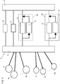
- the plant according to the invention for the management of gases produced in a decentralized way - in particular renewable gases, such as biomethane, for example - comprises at least two devices, respectively at least one gas inlet apparatus 6 and at least one apparatus, according to the invention, for the re-introduction of gas 3, to be interposed between a first gas network 4 and a second gas network 5.
- the gas present in the first network 4 is at a substantially higher pressure than that of the gas present in the second network 5.
- the first network 4 can also be defined as “higher pressure network” while the second network 5 can also be defined as “lower pressure network”.
- the second lower pressure network 5 can receive the gas produced in a decentralized way from a production plant P 1 , P 2 ,... P n . Furthermore, a plurality of users U 1 , U 2 ,..., U n are connected to the second network at lower pressure which require the gas circulating in said second network for their use.
- the second network 5 is a network in which the gas already produced circulates, and is substantially ready for distribution. In particular, therefore, the second network 5 is substantially in direct fluidic connection with the production plant P 1 , P 2 , ... P n , but does not include and/or does not correspond with said gas production plant. Conveniently, gas from the first network 4 circulates in the second network 5.
- the gas present in the first network 4 has characteristics, in particular in terms of composition and preferably due to restrictions in use, which are different than those of the gas present in the second network 5.
- the gas circulating in the first network 4 is at a pressure of 5 - 70 bar.
- the first network 4 is a transport network and/or a gas storage system.
- the first network 4 is a network that does not directly receive the gas produced by the gas production plant P 1 , P 2 , ... P n and, therefore, is not in direct fluidic connection with said plant.
- the gas circulating in the second network 5 is at a pressure of substantially 1.5 - 8 bar.
- the second network 5 is a gas distribution network to a series of users U 1 , U 2 ,..., U n connected/associated to it.
- the gas supply apparatus 3 is not intended to be interposed between the production plant P 1 , P 2 , ... P n and a gas distribution or transport network, and this also applies to the gas inlet 6.
- the inlet apparatus 6 is configured to take/receive the gas from the first network at higher pressure 4 and inject it into the second network at lower pressure 5.
- the inlet 6 is configured to allow the direct flow of gas from the first network 4 at higher pressure towards the second network 5 at lower pressure.
- the inlet apparatus 6 is connected at the inlet 30 and upstream with the first higher pressure network 4, while at the outlet 31 and downstream it is connected with the second lower pressure network 5.
- the inlet apparatus 6 is substantially of the traditional type.
- the inlet apparatus 6 may comprise at least:
- the pressure reduction module 32 is configured to adapt the pressure of the gas present in the first network 4 to that provided in the second network 5 and, in particular, at a pressure suitable for the delivery of the gas to the users U 1 , U 2 , ..., U n associated with said second network.
- the reduction module 32 can be positioned upstream and/or downstream with respect to the measuring module 33.
- the gas inlet apparatus 6 also comprises an odorization module 34 configured to add an odorant to the gas which, by passing through the inlet device 6, passes from the first network 4 to the second network 5.
- an odorization module 34 configured to add an odorant to the gas which, by passing through the inlet device 6, passes from the first network 4 to the second network 5.
- the measuring module 33 can be positioned upstream and/or downstream with respect to the odorization module 34.
- the gas re-injection apparatus 3 is configured to take/receive the gas that circulates in the second lower pressure network 5 (and which was previously introduced by the gas inlet apparatus 6 and/or by the system P 1 , P 2 , ... P n gas production in a decentralized way) to return it - preferably under certain conditions - to the first higher pressure network 4.
- the gas re-injection apparatus 3 is configured to allow - preferably upon the occurrence of certain conditions - a gas flow that is inverse with respect to that allowed/defined by the inlet apparatus 6, that is, to allow a flow of gas from the second network 5 to the first network 4.
- the gas re-injection apparatus 3 is connected upstream with the second lower pressure network 5, while downstream it is connected to the first higher pressure network 4.
- the inlet 20 of the gas re-injection apparatus 3 can be connected upstream to the second lower pressure network 5 by means of the same conduit 45 which connects the outlet 31 of the inlet apparatus 6 to said second network 5.
- the outlet 21 of the gas re-injection apparatus 3 can be connected downstream to the first network 4 at higher pressure by means of the same conduit 46 which connects the inlet 30 of the gas inlet apparatus 6 to said first network 4.
- the inlet 20 of the gas re-injection apparatus 3 can be connected upstream directly to the second network 5 at lower pressure by means of a dedicated conduit 47, while the outlet 21 of said apparatus 3 can be connected downstream directly to the first network 4 by means of a further dedicated conduit 48.
- the flow which passes, through the inlet apparatus 6, from the first network 4 with higher pressure to the second network 5 with lower pressure is hereinafter also referred to as “direct flow”; the flow that passes through the gas re-injection apparatus 3 from the second lower pressure network 5 to the first higher pressure network 4 is also defined hereinafter as “reverse flow”.
- the gas re-injection apparatus 3 is configured to receive the gas from the second lower pressure network 5 and to compress it (i.e. increase its pressure) and modify it in terms of composition so that it can be re-introduced and accepted in the first network 4 at higher pressure.
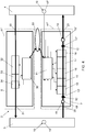
- the inlet apparatus 6 and the gas re-injection apparatus 3 can be integrated within a single station or structure 40 (see fig. 2 ) or can be incorporated in two separate and distinct stations or structures respectively 41' and 41" (see fig. 3 ).
- the inlet apparatus 6 can be installed in combination (i.e. be coupled and connected) to the inlet apparatus 3, or it could be installed independently of the latter.
- the gas re-injection apparatus 3 comprises and/or is associated with a control unit 11 (for example a processor).
- a control unit 11 for example a processor
- the inlet apparatus 6 can comprise its own and distinct control unit 36 which is connected and communicates directly with the control unit 11 of the gas re-injection apparatus 3 (see Figs. 2 , 3 and 5 ).
- the control unit 11 of the gas re-injection apparatus 3 and the control unit 36 of the inlet apparatus 6 can be connected to a central management unit 50 of the entire plant 2 and, therefore, communicate with each other through said central management unit.
- the same control unit 11 can be shared between the inlet apparatus 6 and the re-inlet apparatus 3.
- control unit 36 of the inlet apparatus 6 is connected to the odorization module 34 so as to command the latter.
- control unit 36 of the inlet apparatus 6 is connected to the measuring module 33 so as to receive the data detected by the latter.
- control unit 36 can also be connected to the reduction module 32 and, in particular, so as to control the latter.
- the gas re-injection apparatus 3 comprises a compression unit 16 of the gas present/coming from the second network 5 at lower pressure and which, entering and passing through the reintroduction equipment 3, is brought back to the first network 4 at higher pressure.
- the compression unit 16 is electrically or gas powered.
- control unit 11 is connected to the compression unit 16 to control its activation/deactivation (i.e. on/off regulation) and/or to modulate its flow rate.
- the compression unit 16 comprises at least one compressor controlled to modulate its flow rate as a function of the gas pressure in the second lower pressure network 5 and the needs/requests of the first higher pressure network 4.
- the gas re-injection apparatus 3 also comprises at least one pressure control device 12.
- this at least one pressure control device 12 comprises at least one shut-off member configured to protect the higher pressure network 4 from overpressure, and/or the lower pressure network 5 from the sub-pressures.
- a first pressure control device 12' is provided at the inlet 20 of the re-injection apparatus 3.
- a second pressure control device 12" is provided at the outlet 21 of the re-injection apparatus 3.
- the control unit 11 can be connected to said first 12' and/or second 12" pressure control device to monitor their state or level of opening/closing.
- the gas re-injection apparatus 3 comprises a gas purification module 10 which, suitably, is configured to adapt the gas present and coming from the second lower pressure network 5 to the gas quality specifications which, according to current legislation or sector, there are provided in the first higher pressure network 4.
- the gas purification module 10 is also configured to protect the appliances and instruments present inside the re-injection apparatus 3.
- the purification module 10 is configured to remove from the gas - which comes from the second lower pressure network 5 and which enters the gas re-injection apparatus 3 - the substances and compounds that are not accepted by the first higher pressure network 4 or that could damage the appliances and/or the instruments of said re-injection apparatus 3.
- the purification module 10 is configured not to cause any change in the calorific value or energy characteristics of the gas.
- the purification module 10 is configured not to perform any addition and/or mixing of the gas - which comes from the second lower pressure network 5 and which enters the gas re-injection apparatus 3 - with further substances or compounds, such as for example air or LPG.
- the purification module 10 comprises a unit configured to remove the odorant, both sulfur-based and sulfur-free, from the gas which is present in the lower pressure network 5 and which enters the re-injection apparatus 3.
- this gas purification module 10 comprises an adsorption unit, for example activated carbon, for removing the odorant.
- the purification module 10 is provided at the inlet 20 of said apparatus and, preferably, is positioned upstream of the remaining modules present in the latter, to thus remove from the gas substances and compounds which could damage the apparatus and/or instruments provided in said re-injection apparatus at the inlet.
- the purification module 10 is provided, inside the re-injection apparatus 3, upstream of the compression unit 16, so as to remove from the gas entering the said compression unit the substances and compounds which could damage it.
- the re-injection apparatus 3 also comprises an analysis module 15 configured to detect the quality and characteristics of the gas present and coming from the second network 5.
- the analysis module 15 comprises at least one analysis apparatus, such as for example a gas chromatograph.
- the analysis module 15 is configured to determine the energy content of the gas and its composition with respect to the specifications foreseen in the higher pressure network 4.
- the analysis module 15 is positioned downstream with respect to the purification module 10 to thus analyse the characteristics of the gas coming out of the latter, and thus verify the effective and adequate removal of the odorant and/or other substances and compounds which are not accepted by the former higher pressure network 4.
- the purification 10 and/or analysis 15 modules are positioned upstream with respect to the compression unit 16.
- the analysis module 15 could also be positioned always inside the gas re-injection apparatus 3 and downstream with respect to the compression unit 16.
- the analysis module 15 can be a dedicated module provided for/in the gas re-injection apparatus 3 (cf. Fig. 2-4 and 6 ), that is, be configured only to analyze the reverse flow of gas that enters and passes through the re-injection apparatus 3.
- the analysis module 15 can also be shared/shared between the re-injection apparatus 3 and the inlet apparatus 6.
- the operation of the analysis module 15 is as follows:
- the analysis module 15 also comprises a sorting group (pneumatic and/or electronic), not shown, which ensures that the analysis refers to the gas that passes through the inlet apparatus 6 or through the re-injection apparatus 3.
- a sorting group pneumatic and/or electronic
- the re-injection apparatus 3 also comprises a measuring module 17.
- this measuring module 17 is configured to carry out the fiscal measurement of the quantity of gas that passes through the re-injection apparatus 3 from the first lower pressure network 4 than the second network 5 at higher pressure.
- the measuring module 17 is suitable for carrying out a gas measurement for tax purposes and, in particular, it is configured to comply with the technical requirements defined by national or supranational (for example European) legislation in order to be used in commercial transactions.
- the measuring module 17 is also configured to perform the calculations under the reference conditions.
- the measuring module 17 can be positioned, inside the re-injection apparatus 3, downstream with respect to the compression unit 16.
- the measuring module 17 can be a dedicated module provided for/in the re-injection equipment 3 (see figs. 2-4 and 6 ), that is, be configured only to measure the flow of inverse gas that enters and passes through the re-injection apparatus 3.
- the measuring module 17 can also be shared between the re-injection apparatus 3 and the inlet apparatus 6.
- the analysis module 15 and the measuring module 17 can be integrated in a single system.
- the analysis module 15 and/or the measuring module 17 of the re-injection apparatus 3 are connected to the control unit 11 to send to the latter the data representative of the detections and/or measurements carried out by said modules.
- the plant 2 also comprises, inside or outside the re-injection apparatus 3, an interception module 18 to allow or interrupt the passage of gas which, leaving the apparatus 3, enters the first higher pressure network 4
- the interception module 18 comprises a valve assembly.
- the control unit 11 is connected to the interception module 18 to correspondingly control its opening/closing.
- control unit 11 when the control unit 11 detects a condition in which the gas quality and the connection profiles are guaranteed and in which the first higher pressure network 4 is receptive, it activates the opening of the interception module 18, thus allowing the gas to pass/enter the first network 4 at higher pressure.
- the interception module 18 can be positioned downstream of the compression unit 16 and/or downstream of the possible measuring module 17.
- the interception module 18 is provided at the outlet 31 of the re-injection apparatus 3.
- the interception module 18 could also be provided externally of the re-injection apparatus 3, preferably in an associated area and/or belonging to the first network 5 at higher pressure.
- sensors 19 are provided inside the re-injection apparatus 3 and/or outside the latter, but always inside the plant 2, to detect and monitor the gas characteristics in terms of pressure. These sensors 19 are preferably connected to the control unit 11 to send to the latter a series of data representative of the detections and/or measurements carried out.
- these sensors 19 can be provided inside the first higher pressure network 4 and/or in the second lower pressure network 5, preferably at the delivery and/or redelivery points of fossil or non-fossil gas and/or at critical points (i.e. where the network pressure can reach minimum values).
- these sensors 19 are connected remotely - via cable and/or wireless - with the control unit 11.
- the detections made by these sensors 19 are sent to the control unit 11 which is configured to define, correspondingly, the setpoints of the reduction module 32 provided in the inlet apparatus 6.
- said sensors 19 comprise pressure and/or flow sensors.
- At least one first sensor 19' is provided which is configured to detect the pressure and/or the gas flow rate in an area upstream of the compression unit 16.
- at least one first sensor 19' is provided which is positioned inside the re-injection apparatus 3 and/or a plurality of first sensors 19' are provided distributed in the second low pressure network 5 to detect the pressure - and in particular a rise in pressure - of the gas circulating/coming from said second low pressure network 5.
- At least one second sensor 19" is provided configured to detect the pressure and/or flow of the gas in an area downstream of the compression unit 16 and, in particular, at the outlet 21 of the gas re-injection apparatus 6.
- At least one second sensor 19" can be provided which is positioned inside the re-injection apparatus 3, preferably between the compression unit 16 and the interception module 18, and/or a plurality of second sensors 19" are provided distributed in the first high pressure network 4 to detect the pressure - and in particular an excessive increase in pressure - of the gas circulating in said first high pressure network 4.
- control unit 11 of the re-injection apparatus 3 is connected:
- control unit 11 of the re-injection apparatus 3 can also be connected to said at least one inlet apparatus 6 and, in particular, to a module (for example to the reduction module 32) or to an interception element provided and/or associated with said apparatus 6, to decrease and/or interrupt the flow of gas entering the second lower pressure network 5.
- a module for example to the reduction module 32
- an interception element provided and/or associated with said apparatus 6, to decrease and/or interrupt the flow of gas entering the second lower pressure network 5.
- control unit 11 of the re-injection apparatus 3 can be connected directly, and therefore communicate directly, with the control unit 36 provided in the inlet apparatus 6 (see figs. 2 and 3 ).
- control unit 11 of the re-injection apparatus 3 can be connected with a central management unit 50 of the entire plant 2 and then this central management unit will be connected and communicate with the control unit provided in the inlet apparatus 6 (see fig. 4 ).
- control unit 11 of the re-injection apparatus 3 is configured so that, if said at least one first sensor 19' detects an increase in the pressure of the gas circulating and/or coming into the second lower pressure network 5 above of a predefined pressure value (or range of values) P x , it controls the activation of the compression unit 16 and/or correspondingly modulates its flow rate and, preferably, also commands the opening of the interception module 18 (to thus allow the gas inlet into the higher pressure network 4) and, preferably, can also send a command to the inlet apparatus 6 to decrease and/or interrupt the flow of gas entering the second lower pressure network 5.
- the flow of gas entering the second lower pressure network 5 could possibly be decreased or interrupted by acting manually and/or mechanically on the inlet apparatus.
- control unit 11 can control the activation/deactivation of the compression unit 16 and, in particular, commands the activation of the compression unit 16 until the pressure upstream of said unit drops below a predefined pressure value (or range of values) P z , lower than P x and suitably settable.
- control unit 11 modulates the flow rate of the compression unit 16 to keep the pressure detected upstream of the latter substantially constant by means of said at least one first sensor 19'.
- control unit 11 is connected to the compression unit 16 by means of an inverter which modulates the flow rate of said compression unit according to the pressure detected upstream by said at least one first sensor 19'; in more detail, as said pressure decreases (in response to the request for gas by the users connected to the lower pressure network 5 or against the re-introduction of gas into the higher pressure network 4 through the re-injection apparatus 6), the control unit 11 controls the reduction of the flow rate of the compression unit 16.
- the aforesaid predefined pressure value (or range)/s P x corresponds to a situation in which there is not sufficient demand of gas to receive all the gas introduced, and therefore there is not sufficient consumption of the latter by the users associated with the second lower pressure network 5, or a portion of this.
- control unit 11 of the re-injection apparatus 3 is also configured so that, if said at least one second sensor 19" detects an increase in the pressure of the gas circulating in the first network at higher pressure 4 above a predefined pressure value (or range of values) P y , commands the deactivation of the compression unit 16 and/or correspondingly modulates its flow rate and, preferably, also commands the closure of the interception module 18 (to interrupt the inlet of the gas in the higher pressure network 4) and, preferably, it can also send a command to the inlet apparatus 6 to activate the passage of gas entering the second lower pressure network 5.
- the aforementioned predefined pressure value/s (or range of value/s) P y corresponds to a situation in which there is an excessive compression of the gas in the first network at higher pressure 4.
- control unit 11 of the re-injection apparatus 3 is configured to optimize the gas recompression energy profiles, activating and controlling the compression unit 16 of the re-injection apparatus 3 only when necessary (i.e. when it has already been minimized or interrupted the flow of gas entering the second network 5 at a lower pressure), thus avoiding any waste of energy.
- control unit 11 of the re-injection apparatus 3 is also configured to minimize the recirculations between the first higher pressure network 4 and the second lower pressure network 5 and this is obtained by acting on the inlet apparatus 6 in such a way to interrupt and/or decrease the flow of gas from said first network 4 to said second network 5.
- control unit 11 of the re-injection apparatus 3 is also configured to guarantee the safety and continuity of gas supply to the network at a lower pressure 5 and, suitably, this can also be achieved thanks to the control device 12' and/or by monitoring the pressure upstream of the re-injection apparatus 3. In this way, therefore, it is ensured that said lower pressure network 5 never runs out of gas, thus allowing it to promptly satisfy the gas requests made by the users associated with said lower pressure network 5.
- control unit 36 of the inlet apparatus 6 is also configured to guarantee the safety and continuity of gas supply to the lower pressure network 5 and, suitably, this can be obtained by acting on the reduction module 32 of the inlet apparatus 6 and/or monitoring the pressure downstream of said reduction module 32. In this way, therefore, it is ensured that said lower pressure network 5 never runs out of gas, thus allowing it to promptly meet gas requests carried out by the users associated with said lower pressure network 5.
- control unit 11 is also configured to ensure that the gas of the reverse flow, that passing from the second lower pressure network 5 to the first higher pressure network 4, complies with the connection profiles required by said higher pressure network 4 in terms of quality, volumes and physical conditions (pressure and temperature) of the gas.
- control unit 11 receives at the inlet the measurements that are carried out, on the gas that comes and passes through the re-injection apparatus 3, by the analysis module 15 and/or by the measuring module 17 and/or from the sensors 19, and correspondingly controls the interception module 18 and/or the compression unit 16; in more detail, if the measurements carried out are not in line with the profiles required by the first higher pressure network 4, the control unit 11 controls the closing of the interception module 18 and/or of the compression unit 16 thus avoiding the entry of gas into said first network 4.
- a software configured and installed to manage the operation of the re-injection apparatus 3 and, in particular, is installed and executed inside the control unit 11 to command the activation/deactivation and/or to control the modulation of the compression unit 16 of said re-injection apparatus 3 - and preferably also of the interception module 18 - and thus allow the passage/block of the reverse flow of gas from the second lower pressure network 5 towards the first higher pressure network 4.
- the software loaded and/or executed in the control unit 11 is configured to exclusively control re-injection apparatus 3 while the inlet apparatus 6 is controlled separately and/or manually as required.
- control unit 11 of the re-injection apparatus 3 can be connected directly (see figs. 2 and 3 ) and/or through a central management unit (see fig. 4 ) and/or can be shared (see fig. 6 ) with the inlet apparatus 6 and is configured to manage its operation so as to allow the passage/blocking (or reduction) of the direct flow of gas from the first higher pressure network 4 towards the second lower pressure network 5.
- the software loaded and/or executed in the control unit 11 is configured to control the passage between:
- the apparatus according to the present invention includes a purification module for removing substances and/or compounds from the gas coming from the second network at a lower pressure 5 not accepted by the first higher pressure network 4, and this is particularly appropriate since the gas present in the first network 4 has characteristics - in particular in terms of composition and preferably due to restrictions in use, and also for gas parameters that do not concern its energy content - which are different than those of the gas present in the second network 5.
Landscapes
- Engineering & Computer Science (AREA)
- Mechanical Engineering (AREA)
- General Engineering & Computer Science (AREA)
- Chemical & Material Sciences (AREA)
- Combustion & Propulsion (AREA)
- Feeding, Discharge, Calcimining, Fusing, And Gas-Generation Devices (AREA)
- Physical Or Chemical Processes And Apparatus (AREA)
- Treating Waste Gases (AREA)
- Crystals, And After-Treatments Of Crystals (AREA)
Priority Applications (1)
| Application Number | Priority Date | Filing Date | Title |
|---|---|---|---|
| EP23201971.1A EP4290122A3 (fr) | 2019-06-03 | 2020-06-03 | Appareil pour une installation de gestion de gaz |
Applications Claiming Priority (1)
| Application Number | Priority Date | Filing Date | Title |
|---|---|---|---|
| IT102019000007911A IT201900007911A1 (it) | 2019-06-03 | 2019-06-03 | Apparecchiatura per un impianto per la gestione di gas prodotti in modo decentralizzato, in particolare gas rinnovabili. |
Related Child Applications (2)
| Application Number | Title | Priority Date | Filing Date |
|---|---|---|---|
| EP23201971.1A Division EP4290122A3 (fr) | 2019-06-03 | 2020-06-03 | Appareil pour une installation de gestion de gaz |
| EP23201971.1A Division-Into EP4290122A3 (fr) | 2019-06-03 | 2020-06-03 | Appareil pour une installation de gestion de gaz |
Publications (3)
| Publication Number | Publication Date |
|---|---|
| EP3748219A1 true EP3748219A1 (fr) | 2020-12-09 |
| EP3748219C0 EP3748219C0 (fr) | 2023-11-15 |
| EP3748219B1 EP3748219B1 (fr) | 2023-11-15 |
Family
ID=68234081
Family Applications (2)
| Application Number | Title | Priority Date | Filing Date |
|---|---|---|---|
| EP20177982.4A Active EP3748219B1 (fr) | 2019-06-03 | 2020-06-03 | Appareil pour une installation de gestion de gaz |
| EP23201971.1A Pending EP4290122A3 (fr) | 2019-06-03 | 2020-06-03 | Appareil pour une installation de gestion de gaz |
Family Applications After (1)
| Application Number | Title | Priority Date | Filing Date |
|---|---|---|---|
| EP23201971.1A Pending EP4290122A3 (fr) | 2019-06-03 | 2020-06-03 | Appareil pour une installation de gestion de gaz |
Country Status (4)
| Country | Link |
|---|---|
| EP (2) | EP3748219B1 (fr) |
| ES (1) | ES2971518T3 (fr) |
| IT (1) | IT201900007911A1 (fr) |
| PL (1) | PL3748219T3 (fr) |
Cited By (2)
| Publication number | Priority date | Publication date | Assignee | Title |
|---|---|---|---|---|
| WO2023047384A1 (fr) * | 2021-09-27 | 2023-03-30 | Regaenergy Group, S.A. | Système de gestion de réseau de gaz décentralisé |
| EP4474691A1 (fr) | 2023-06-06 | 2024-12-11 | Inrete Distribuzione Energia S.p.A. | Dispositif pour inverser l'écoulement dans des réseaux de distribution de gaz naturel |
Citations (6)
| Publication number | Priority date | Publication date | Assignee | Title |
|---|---|---|---|---|
| DE102009048833A1 (de) * | 2008-10-21 | 2010-04-22 | Franz Griesmaier | Verfahren zur Reinigung von Biogas |
| DE102008058736B3 (de) | 2008-11-24 | 2010-08-05 | Technische Universität Clausthal | Verfahren zum Betreiben eines Gasnetzes |
| DE102009038128A1 (de) | 2009-08-11 | 2011-02-24 | EnBW Energie Baden-Württemberg AG | Verfahren und Vorrichtung zur Einspeisung von Biogas in ein Gasnetz |
| DE102013011289A1 (de) | 2013-07-08 | 2015-01-08 | Vattenfall Europe New Energy Gmbh | Verfahren zur gepoolten Verwertung von dezentral erzeugtem Biogas |
| US20160247167A1 (en) | 2015-02-23 | 2016-08-25 | Iogen Corporation | Pipeline arrangement for utilizing a gas comprising biomethane |
| FR3035598A1 (fr) | 2015-04-29 | 2016-11-04 | Endel | Procede et systeme d'injection directe de biomethane issu de biogaz au sein d'un reseau de distribution. |
-
2019
- 2019-06-03 IT IT102019000007911A patent/IT201900007911A1/it unknown
-
2020
- 2020-06-03 ES ES20177982T patent/ES2971518T3/es active Active
- 2020-06-03 EP EP20177982.4A patent/EP3748219B1/fr active Active
- 2020-06-03 PL PL20177982.4T patent/PL3748219T3/pl unknown
- 2020-06-03 EP EP23201971.1A patent/EP4290122A3/fr active Pending
Patent Citations (6)
| Publication number | Priority date | Publication date | Assignee | Title |
|---|---|---|---|---|
| DE102009048833A1 (de) * | 2008-10-21 | 2010-04-22 | Franz Griesmaier | Verfahren zur Reinigung von Biogas |
| DE102008058736B3 (de) | 2008-11-24 | 2010-08-05 | Technische Universität Clausthal | Verfahren zum Betreiben eines Gasnetzes |
| DE102009038128A1 (de) | 2009-08-11 | 2011-02-24 | EnBW Energie Baden-Württemberg AG | Verfahren und Vorrichtung zur Einspeisung von Biogas in ein Gasnetz |
| DE102013011289A1 (de) | 2013-07-08 | 2015-01-08 | Vattenfall Europe New Energy Gmbh | Verfahren zur gepoolten Verwertung von dezentral erzeugtem Biogas |
| US20160247167A1 (en) | 2015-02-23 | 2016-08-25 | Iogen Corporation | Pipeline arrangement for utilizing a gas comprising biomethane |
| FR3035598A1 (fr) | 2015-04-29 | 2016-11-04 | Endel | Procede et systeme d'injection directe de biomethane issu de biogaz au sein d'un reseau de distribution. |
Non-Patent Citations (2)
| Title |
|---|
| JENS DAROCHA ET AL: "The Power Pioneers Bio-Natural Gas Plant Emmertsbühl Feeding biogas into the natural gas grid Emmertsbühl, 27 th April 2012 Bio-Natural Gas Plant Emmertsbühl", 27 April 2012 (2012-04-27), XP055581239, Retrieved from the Internet <URL:http://static.wm3.se/sites/2/media/13436_Arkiv_Emmertsbuehl_20120427.pdf?1402830868> [retrieved on 20190415] * |
| PHIL WINNARD: "IFI CAPACITY ENHANCEMENT PROJECT MP TO IP NETWORK COMPRESSION", 17 October 2012 (2012-10-17), XP055558364, Retrieved from the Internet <URL:http://www.biogas.org.uk/images/upload/news_53_Skipton-Within-Network-Compressor-CNG-Services.pdf> [retrieved on 20190218] * |
Cited By (2)
| Publication number | Priority date | Publication date | Assignee | Title |
|---|---|---|---|---|
| WO2023047384A1 (fr) * | 2021-09-27 | 2023-03-30 | Regaenergy Group, S.A. | Système de gestion de réseau de gaz décentralisé |
| EP4474691A1 (fr) | 2023-06-06 | 2024-12-11 | Inrete Distribuzione Energia S.p.A. | Dispositif pour inverser l'écoulement dans des réseaux de distribution de gaz naturel |
Also Published As
| Publication number | Publication date |
|---|---|
| PL3748219T3 (pl) | 2024-04-08 |
| EP4290122A3 (fr) | 2024-03-06 |
| EP3748219C0 (fr) | 2023-11-15 |
| ES2971518T3 (es) | 2024-06-05 |
| IT201900007911A1 (it) | 2020-12-03 |
| EP4290122A2 (fr) | 2023-12-13 |
| EP3748219B1 (fr) | 2023-11-15 |
Similar Documents
| Publication | Publication Date | Title |
|---|---|---|
| EP3748219B1 (fr) | Appareil pour une installation de gestion de gaz | |
| CN105045089A (zh) | 一种基于出口NOx含量控制的锅炉脱硝控制方法及系统 | |
| MX2009007769A (es) | Control de espira cerrada para dosificacion de fluidos de sistema de escape. | |
| CN216997679U (zh) | 一种氮气回收系统 | |
| CN203668323U (zh) | 水煤浆气化炉的进料系统及其煤气化系统 | |
| CN104132241A (zh) | Lng储罐bog放散回收装置及控制方法 | |
| CN116263236A (zh) | 一种已建天然气管道安全掺氢系统与方法 | |
| CN106764437A (zh) | 一种多气源城市燃气供气系统 | |
| CN210424507U (zh) | 燃气调压撬 | |
| SE1550799A1 (sv) | Startup / shutdown hydrogen injection system for boiling water reactors (bwrs), and method thereof | |
| CN204127659U (zh) | Lng储罐bog放散回收装置 | |
| CN204437711U (zh) | 一种沼气站的中压管网进气检测控制系统 | |
| CN205559107U (zh) | 一种天然气发动机供气系统 | |
| CN201944547U (zh) | 压缩天然气供气站的系统 | |
| CN217899866U (zh) | 多种燃气混合装置 | |
| CN213930425U (zh) | 燃气管网智能安全控制系统 | |
| CN201609630U (zh) | 一种新型氧化反应器 | |
| CN2844641Y (zh) | 瓶组型橇装式lng供气终端 | |
| CN203546823U (zh) | 一种消防给水设备 | |
| CN209005492U (zh) | 柴油加氢装置废氢处理系统 | |
| CN222669685U (zh) | 退火裂解炉安全供气管路系统 | |
| EP4474691A1 (fr) | Dispositif pour inverser l'écoulement dans des réseaux de distribution de gaz naturel | |
| CN211624872U (zh) | 一种蒸汽减压系统 | |
| CN114987792B (zh) | 导管管内多余物检测装置和使用方法 | |
| CN112413405B (zh) | 一种移动式调压集成供气设备 |
Legal Events
| Date | Code | Title | Description |
|---|---|---|---|
| PUAI | Public reference made under article 153(3) epc to a published international application that has entered the european phase |
Free format text: ORIGINAL CODE: 0009012 |
|
| STAA | Information on the status of an ep patent application or granted ep patent |
Free format text: STATUS: THE APPLICATION HAS BEEN PUBLISHED |
|
| AK | Designated contracting states |
Kind code of ref document: A1 Designated state(s): AL AT BE BG CH CY CZ DE DK EE ES FI FR GB GR HR HU IE IS IT LI LT LU LV MC MK MT NL NO PL PT RO RS SE SI SK SM TR |
|
| AX | Request for extension of the european patent |
Extension state: BA ME |
|
| STAA | Information on the status of an ep patent application or granted ep patent |
Free format text: STATUS: REQUEST FOR EXAMINATION WAS MADE |
|
| 17P | Request for examination filed |
Effective date: 20210608 |
|
| RBV | Designated contracting states (corrected) |
Designated state(s): AL AT BE BG CH CY CZ DE DK EE ES FI FR GB GR HR HU IE IS IT LI LT LU LV MC MK MT NL NO PL PT RO RS SE SI SK SM TR |
|
| INTG | Intention to grant announced |
Effective date: 20221215 |
|
| GRAJ | Information related to disapproval of communication of intention to grant by the applicant or resumption of examination proceedings by the epo deleted |
Free format text: ORIGINAL CODE: EPIDOSDIGR1 |
|
| GRAP | Despatch of communication of intention to grant a patent |
Free format text: ORIGINAL CODE: EPIDOSNIGR1 |
|
| STAA | Information on the status of an ep patent application or granted ep patent |
Free format text: STATUS: GRANT OF PATENT IS INTENDED |
|
| INTC | Intention to grant announced (deleted) | ||
| INTG | Intention to grant announced |
Effective date: 20230612 |
|
| GRAS | Grant fee paid |
Free format text: ORIGINAL CODE: EPIDOSNIGR3 |
|
| GRAA | (expected) grant |
Free format text: ORIGINAL CODE: 0009210 |
|
| STAA | Information on the status of an ep patent application or granted ep patent |
Free format text: STATUS: THE PATENT HAS BEEN GRANTED |
|
| AK | Designated contracting states |
Kind code of ref document: B1 Designated state(s): AL AT BE BG CH CY CZ DE DK EE ES FI FR GB GR HR HU IE IS IT LI LT LU LV MC MK MT NL NO PL PT RO RS SE SI SK SM TR |
|
| REG | Reference to a national code |
Ref country code: CH Ref legal event code: EP Ref country code: GB Ref legal event code: FG4D |
|
| REG | Reference to a national code |
Ref country code: DE Ref legal event code: R096 Ref document number: 602020020965 Country of ref document: DE |
|
| REG | Reference to a national code |
Ref country code: IE Ref legal event code: FG4D |
|
| U01 | Request for unitary effect filed |
Effective date: 20231207 |
|
| U07 | Unitary effect registered |
Designated state(s): AT BE BG DE DK EE FI FR IT LT LU LV MT NL PT SE SI Effective date: 20231214 |
|
| REG | Reference to a national code |
Ref country code: SK Ref legal event code: T3 Ref document number: E 43312 Country of ref document: SK |
|
| PG25 | Lapsed in a contracting state [announced via postgrant information from national office to epo] |
Ref country code: GR Free format text: LAPSE BECAUSE OF FAILURE TO SUBMIT A TRANSLATION OF THE DESCRIPTION OR TO PAY THE FEE WITHIN THE PRESCRIBED TIME-LIMIT Effective date: 20240216 |
|
| PG25 | Lapsed in a contracting state [announced via postgrant information from national office to epo] |
Ref country code: IS Free format text: LAPSE BECAUSE OF FAILURE TO SUBMIT A TRANSLATION OF THE DESCRIPTION OR TO PAY THE FEE WITHIN THE PRESCRIBED TIME-LIMIT Effective date: 20240315 |
|
| PG25 | Lapsed in a contracting state [announced via postgrant information from national office to epo] |
Ref country code: IS Free format text: LAPSE BECAUSE OF FAILURE TO SUBMIT A TRANSLATION OF THE DESCRIPTION OR TO PAY THE FEE WITHIN THE PRESCRIBED TIME-LIMIT Effective date: 20240315 Ref country code: GR Free format text: LAPSE BECAUSE OF FAILURE TO SUBMIT A TRANSLATION OF THE DESCRIPTION OR TO PAY THE FEE WITHIN THE PRESCRIBED TIME-LIMIT Effective date: 20240216 |
|
| PG25 | Lapsed in a contracting state [announced via postgrant information from national office to epo] |
Ref country code: RS Free format text: LAPSE BECAUSE OF FAILURE TO SUBMIT A TRANSLATION OF THE DESCRIPTION OR TO PAY THE FEE WITHIN THE PRESCRIBED TIME-LIMIT Effective date: 20231115 Ref country code: NO Free format text: LAPSE BECAUSE OF FAILURE TO SUBMIT A TRANSLATION OF THE DESCRIPTION OR TO PAY THE FEE WITHIN THE PRESCRIBED TIME-LIMIT Effective date: 20240215 Ref country code: HR Free format text: LAPSE BECAUSE OF FAILURE TO SUBMIT A TRANSLATION OF THE DESCRIPTION OR TO PAY THE FEE WITHIN THE PRESCRIBED TIME-LIMIT Effective date: 20231115 |
|
| REG | Reference to a national code |
Ref country code: ES Ref legal event code: FG2A Ref document number: 2971518 Country of ref document: ES Kind code of ref document: T3 Effective date: 20240605 |
|
| U20 | Renewal fee for the european patent with unitary effect paid |
Year of fee payment: 5 Effective date: 20240613 |
|
| PG25 | Lapsed in a contracting state [announced via postgrant information from national office to epo] |
Ref country code: SM Free format text: LAPSE BECAUSE OF FAILURE TO SUBMIT A TRANSLATION OF THE DESCRIPTION OR TO PAY THE FEE WITHIN THE PRESCRIBED TIME-LIMIT Effective date: 20231115 Ref country code: RO Free format text: LAPSE BECAUSE OF FAILURE TO SUBMIT A TRANSLATION OF THE DESCRIPTION OR TO PAY THE FEE WITHIN THE PRESCRIBED TIME-LIMIT Effective date: 20231115 |
|
| REG | Reference to a national code |
Ref country code: DE Ref legal event code: R097 Ref document number: 602020020965 Country of ref document: DE |
|
| PLBE | No opposition filed within time limit |
Free format text: ORIGINAL CODE: 0009261 |
|
| STAA | Information on the status of an ep patent application or granted ep patent |
Free format text: STATUS: NO OPPOSITION FILED WITHIN TIME LIMIT |
|
| 26N | No opposition filed |
Effective date: 20240819 |
|
| PG25 | Lapsed in a contracting state [announced via postgrant information from national office to epo] |
Ref country code: MC Free format text: LAPSE BECAUSE OF FAILURE TO SUBMIT A TRANSLATION OF THE DESCRIPTION OR TO PAY THE FEE WITHIN THE PRESCRIBED TIME-LIMIT Effective date: 20231115 |
|
| REG | Reference to a national code |
Ref country code: CH Ref legal event code: PL |
|
| PG25 | Lapsed in a contracting state [announced via postgrant information from national office to epo] |
Ref country code: IE Free format text: LAPSE BECAUSE OF NON-PAYMENT OF DUE FEES Effective date: 20240603 |
|
| PG25 | Lapsed in a contracting state [announced via postgrant information from national office to epo] |
Ref country code: CH Free format text: LAPSE BECAUSE OF NON-PAYMENT OF DUE FEES Effective date: 20240630 |
|
| U20 | Renewal fee for the european patent with unitary effect paid |
Year of fee payment: 6 Effective date: 20250520 |
|
| PGFP | Annual fee paid to national office [announced via postgrant information from national office to epo] |
Ref country code: PL Payment date: 20250521 Year of fee payment: 6 |
|
| PGFP | Annual fee paid to national office [announced via postgrant information from national office to epo] |
Ref country code: GB Payment date: 20250520 Year of fee payment: 6 |
|
| PGFP | Annual fee paid to national office [announced via postgrant information from national office to epo] |
Ref country code: SK Payment date: 20250521 Year of fee payment: 6 |
|
| PGFP | Annual fee paid to national office [announced via postgrant information from national office to epo] |
Ref country code: CZ Payment date: 20250528 Year of fee payment: 6 |
|
| PG25 | Lapsed in a contracting state [announced via postgrant information from national office to epo] |
Ref country code: CY Free format text: LAPSE BECAUSE OF FAILURE TO SUBMIT A TRANSLATION OF THE DESCRIPTION OR TO PAY THE FEE WITHIN THE PRESCRIBED TIME-LIMIT; INVALID AB INITIO Effective date: 20200603 |
|
| PGFP | Annual fee paid to national office [announced via postgrant information from national office to epo] |
Ref country code: ES Payment date: 20250708 Year of fee payment: 6 |
|
| PG25 | Lapsed in a contracting state [announced via postgrant information from national office to epo] |
Ref country code: HU Free format text: LAPSE BECAUSE OF FAILURE TO SUBMIT A TRANSLATION OF THE DESCRIPTION OR TO PAY THE FEE WITHIN THE PRESCRIBED TIME-LIMIT; INVALID AB INITIO Effective date: 20200603 |