EP3748228A2 - Brûleur à température de flamme et émission d'oxydes d'azote réduites - Google Patents
Brûleur à température de flamme et émission d'oxydes d'azote réduites Download PDFInfo
- Publication number
- EP3748228A2 EP3748228A2 EP20178158.0A EP20178158A EP3748228A2 EP 3748228 A2 EP3748228 A2 EP 3748228A2 EP 20178158 A EP20178158 A EP 20178158A EP 3748228 A2 EP3748228 A2 EP 3748228A2
- Authority
- EP
- European Patent Office
- Prior art keywords
- burner
- fuel
- fuel nozzle
- nozzle system
- burner according
- Prior art date
- Legal status (The legal status is an assumption and is not a legal conclusion. Google has not performed a legal analysis and makes no representation as to the accuracy of the status listed.)
- Withdrawn
Links
Images


Classifications
-
- F—MECHANICAL ENGINEERING; LIGHTING; HEATING; WEAPONS; BLASTING
- F23—COMBUSTION APPARATUS; COMBUSTION PROCESSES
- F23D—BURNERS
- F23D11/00—Burners using a direct spraying action of liquid droplets or vaporised liquid into the combustion space
- F23D11/36—Details
- F23D11/38—Nozzles; Cleaning devices therefor
- F23D11/383—Nozzles; Cleaning devices therefor with swirl means
-
- F—MECHANICAL ENGINEERING; LIGHTING; HEATING; WEAPONS; BLASTING
- F23—COMBUSTION APPARATUS; COMBUSTION PROCESSES
- F23D—BURNERS
- F23D11/00—Burners using a direct spraying action of liquid droplets or vaporised liquid into the combustion space
- F23D11/36—Details
- F23D11/40—Mixing tubes; Burner heads
- F23D11/406—Flame stabilising means, e.g. flame holders
-
- F—MECHANICAL ENGINEERING; LIGHTING; HEATING; WEAPONS; BLASTING
- F23—COMBUSTION APPARATUS; COMBUSTION PROCESSES
- F23D—BURNERS
- F23D14/00—Burners for combustion of a gas, e.g. of a gas stored under pressure as a liquid
- F23D14/20—Non-premix gas burners, i.e. in which gaseous fuel is mixed with combustion air on arrival at the combustion zone
- F23D14/22—Non-premix gas burners, i.e. in which gaseous fuel is mixed with combustion air on arrival at the combustion zone with separate air and gas feed ducts, e.g. with ducts running parallel or crossing each other
- F23D14/24—Non-premix gas burners, i.e. in which gaseous fuel is mixed with combustion air on arrival at the combustion zone with separate air and gas feed ducts, e.g. with ducts running parallel or crossing each other at least one of the fluids being submitted to a swirling motion
-
- F—MECHANICAL ENGINEERING; LIGHTING; HEATING; WEAPONS; BLASTING
- F23—COMBUSTION APPARATUS; COMBUSTION PROCESSES
- F23D—BURNERS
- F23D14/00—Burners for combustion of a gas, e.g. of a gas stored under pressure as a liquid
- F23D14/46—Details
- F23D14/48—Nozzles
- F23D14/58—Nozzles characterised by the shape or arrangement of the outlet or outlets from the nozzle, e.g. of annular configuration
-
- F—MECHANICAL ENGINEERING; LIGHTING; HEATING; WEAPONS; BLASTING
- F23—COMBUSTION APPARATUS; COMBUSTION PROCESSES
- F23D—BURNERS
- F23D14/00—Burners for combustion of a gas, e.g. of a gas stored under pressure as a liquid
- F23D14/46—Details
- F23D14/70—Baffles or like flow-disturbing devices
-
- F—MECHANICAL ENGINEERING; LIGHTING; HEATING; WEAPONS; BLASTING
- F23—COMBUSTION APPARATUS; COMBUSTION PROCESSES
- F23D—BURNERS
- F23D17/00—Burners for combustion simultaneously or alternately of gaseous or liquid or pulverulent fuel
- F23D17/002—Burners for combustion simultaneously or alternately of gaseous or liquid or pulverulent fuel gaseous or liquid fuel
-
- F—MECHANICAL ENGINEERING; LIGHTING; HEATING; WEAPONS; BLASTING
- F23—COMBUSTION APPARATUS; COMBUSTION PROCESSES
- F23D—BURNERS
- F23D2209/00—Safety arrangements
- F23D2209/10—Flame flashback
-
- F—MECHANICAL ENGINEERING; LIGHTING; HEATING; WEAPONS; BLASTING
- F23—COMBUSTION APPARATUS; COMBUSTION PROCESSES
- F23D—BURNERS
- F23D2209/00—Safety arrangements
- F23D2209/20—Flame lift-off / stability
-
- F—MECHANICAL ENGINEERING; LIGHTING; HEATING; WEAPONS; BLASTING
- F23—COMBUSTION APPARATUS; COMBUSTION PROCESSES
- F23D—BURNERS
- F23D2900/00—Special features of, or arrangements for burners using fluid fuels or solid fuels suspended in a carrier gas
- F23D2900/14—Special features of gas burners
- F23D2900/14003—Special features of gas burners with more than one nozzle
-
- F—MECHANICAL ENGINEERING; LIGHTING; HEATING; WEAPONS; BLASTING
- F23—COMBUSTION APPARATUS; COMBUSTION PROCESSES
- F23D—BURNERS
- F23D2900/00—Special features of, or arrangements for burners using fluid fuels or solid fuels suspended in a carrier gas
- F23D2900/14—Special features of gas burners
- F23D2900/14641—Special features of gas burners with gas distribution manifolds or bars provided with a plurality of nozzles
-
- F—MECHANICAL ENGINEERING; LIGHTING; HEATING; WEAPONS; BLASTING
- F23—COMBUSTION APPARATUS; COMBUSTION PROCESSES
- F23N—REGULATING OR CONTROLLING COMBUSTION
- F23N2229/00—Flame sensors
- F23N2229/12—Flame sensors with flame rectification current detecting means
-
- F—MECHANICAL ENGINEERING; LIGHTING; HEATING; WEAPONS; BLASTING
- F23—COMBUSTION APPARATUS; COMBUSTION PROCESSES
- F23N—REGULATING OR CONTROLLING COMBUSTION
- F23N2229/00—Flame sensors
- F23N2229/20—Camera viewing
-
- Y—GENERAL TAGGING OF NEW TECHNOLOGICAL DEVELOPMENTS; GENERAL TAGGING OF CROSS-SECTIONAL TECHNOLOGIES SPANNING OVER SEVERAL SECTIONS OF THE IPC; TECHNICAL SUBJECTS COVERED BY FORMER USPC CROSS-REFERENCE ART COLLECTIONS [XRACs] AND DIGESTS
- Y02—TECHNOLOGIES OR APPLICATIONS FOR MITIGATION OR ADAPTATION AGAINST CLIMATE CHANGE
- Y02E—REDUCTION OF GREENHOUSE GAS [GHG] EMISSIONS, RELATED TO ENERGY GENERATION, TRANSMISSION OR DISTRIBUTION
- Y02E20/00—Combustion technologies with mitigation potential
- Y02E20/34—Indirect CO2mitigation, i.e. by acting on non CO2directly related matters of the process, e.g. pre-heating or heat recovery
Definitions
- the invention relates to a burner with reduced flame temperature and nitrogen oxide emissions.
- a burner with a burner head which essentially has a tubular channel, in which the oxygen carrier, for example air, flows out via a fan and mixes with the fuel, for example gas, is used a distribution system is directed into a tubular channel.
- An ignition device ignites the mixture of oxygen carrier and fuel, which initiates combustion.
- Such burner heads represent a burden for the environment, since they emit nitrogen oxides (NO x ) generated during combustion into the atmosphere. For this reason, burners with burner heads have already been developed in which the production of these nitrogen oxides can be reduced.
- NO x nitrogen oxides
- a burner head is known in which the reduction in nitrogen oxides is achieved with the aid of distributor devices when the fuel is supplied.
- the distributor is located inside the front part of the supply pipe for the combustion air and consists of annular spaces which run at right angles to the axis of the supply pipe and are delimited by coaxial rings which are connected to one another via spacer elements.
- a burner head for burners with a tubular body for supplying an oxygen carrier into a combustion chamber in which one or more pipes are provided for supplying a fuel into the combustion chamber, the pipes running in the tubular body and via a feed channel with the Fuel are supplied.
- a converging transition piece is provided at the end of the tubular body, which protrudes into the combustion chamber, the convergence pointing into the interior of the combustion chamber.
- oxidizing agents preferably air
- oxygen burned with a fuel in the combustion chamber in a continuous reaction with the release of heat.
- the heated exhaust gases are released into the open environment through the opening and can be used, for example, in all types of heating systems, drying systems, thermal post-combustion systems, environmental systems, curing ovens or in other process engineering systems.
- purified gases such as town, long-distance, natural or liquid gas and mixtures thereof come into consideration as fuel. Heating oil, petroleum and other liquid or pasty fuels can also be burned.
- the aim of the invention is therefore to reconcile the advantages of burners of the second category with the advantages of burners of the first category, that is, on the one hand, to reliably exclude flashbacks, but at the same time to ensure high homogeneity of the mixture and thus both the flame temperature and the Reduce nitrogen emissions.
- the DE 10 2018 112 540 Applicant already has a fuel nozzle system that is essentially circular and is set up so that it generates a leaner mixture on at least one outer ring and a richer mixture, in particular a fuel / oxidizer mixture, on at least one inner ring. Also the DE 10 2017 116 529 the applicant pursues the goal of optimizing the combustion process by achieving better homogeneity of the mixture in the combustion chamber.
- the present invention develops the basic idea and improves these findings and studies.
- the elements of the fuel nozzle system be made as thin, slender and streamlined as possible. It has been found that turbulence occurs at each leading edge, since this air flow has to flow around every component built into the air flow. Recirculations also occur in the turbulence zones at the trailing edge located downstream. These eddies, in particular the recirculations, lead to a mixing of the inner richer and outer leaner fuel-air mixture. This in turn leads to an increased flame temperature and thus to increased nitrogen oxide formation.
- the invention also provides that the area ratio of the inner ring to the area ratio of the outer ring is 1: 2.5 to 1: 3.9, preferably exactly 1: 3.1.
- the maximum swirl angle ( ⁇ ) of the fuel nozzle system on the outside is between 30 ° to 60 °, preferably exactly 48 °.
- the first small recirculations begin to form in the outer area.
- the twist must therefore not be greater than specified.
- the swirl is still strong enough to stabilize the flame. At lower helix angles, however, the flame becomes unstable.
- the swirl is only necessary to create stable conditions in the flame. However, there must be no jump in the twist between the inner, richer area and the outer, leaner area, as otherwise the inner and outer areas would mix at this shear surface. Since little or no twist is advantageous in the inner area, but twist is necessary in the outer area and no jump from the inside to the outside should be generated, the twist must decrease continuously from the outside to the inside.
- the swirl elements are designed in an arc shape.
- such arcuate blades form significantly fewer recirculations than straight blades.
- the air is carried along in the direction of flow, the direction change takes place gently along the arch.
- the helix angle ( ⁇ ) is on the inside at 0, that is to say decreases from the outside inwards to 0.
- the fuel nozzle system has a perforated plate upstream for homogenizing the air flow in front of the mixing unit over the entire cross section.
- the combustion air supplied through the housing must hit the mixing unit with a flow velocity that is the same over the cross section, so that a homogeneous gas-air mixture inside and outside can arise.
- the deflection of the combustion air when it enters the burner housing results in very different flow speeds. These are canceled and homogenized by the proposed perforated plate in front of the mixing unit.
- the installation space between the perforated plate and the inner ring should only have electrodes and no other components. Any turbulence must be avoided before the air flow hits the mixing unit. In one embodiment, feeding the electrodes from the side is also conceivable. This would be an additional advantage for the burner, albeit rather difficult to achieve in practice.
- At least one double-walled tube is provided for transporting fuel outside the housing cross-section to the fuel nozzle system. This arrangement also pursues the goal of not generating any turbulence.
- At least one double-walled tube is provided on the very outside within the burner cross-section for transporting fuel on the edge of the housing cross-section to the fuel nozzle system.
- turbulence through the double-walled pipe cannot be avoided, they do less damage outside than inside.
- the cross section of the swirl generator should be designed so that the fuel is guided inwards. In this way no additional gas ducts are necessary. Otherwise, these also generate turbulence and recirculation.
- a partition wall can be provided between the interior and exterior of the fuel nozzle system. In this way, when the swirl is generated, the air flow is directed axially, possibly in addition to the perforated plate according to the invention in front of the mixing unit.
- the dividing wall and the lip of the fuel nozzle system can also run tangentially through the inner area of the flame monitoring device, since an ignitable mixture that can be ignited immediately is also present here.
- a flame forms immediately behind the lip, which is necessary to monitor the flame with the help of an electrode. No flame signal can be measured by ionization at any other location than the one suggested.
- the burner mouth leading into the combustion chamber is alternatively or cumulatively designed as a straight tube.
- Many known burners have a conical burner mouth. Although this has a positive effect on the flame stability, it causes strong turbulence and recirculation, which also has a negative effect on nitrogen oxide emissions.
- the substance in particular the fuel from the channel system of the fuel nozzle system, meet the swirl of the oxidizer at a right angle.
- the flows meet at a large angle, good oxidizer and fuel mixing is created.
- the maximum angle at which the two media may meet is 90 ° without the risk of fuel getting upstream in front of the mixing unit.
- the middle area of the mixing unit is designed in such a way that a UV sensor can detect the flame behind it.
- the flame can also be monitored optically for monitoring with an electrode and an ionization signal.
- the prerequisite for this is that there is a peephole through which an optical sensor can detect the flame.
- a viewing tube is required from the end flange of the burner housing to the perforated plate.
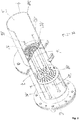
- a burner generally designated 1
- a fuel nozzle system 5 is arranged in the housing 2, the double-walled tube 15 of which lies outside the cross section of the housing 2.
- An ignition device 16 and a flame monitoring device 17 are located inside the housing 2, in which supports 19, 20 penetrate the fuel nozzle system 5 the flame monitoring 17 is penetrated.
- Figure 2 shows a modified embodiment in which a fuel nozzle system 5 'is provided with a double-walled tube 15' arranged within the cross section of the housing 2.
- Fig. 3 shows a plan view of the fuel nozzle system 5 with a double-walled tube 15 outside the cross section of the housing 2 from the front, that is to say from a downstream perspective.
- the outer ring 12 which is divided into 32 sub-segments, for example by larger fins 8, forms a first air cross-section 10 on the outside, while the inner ring 13, which is segmented, for example, by smaller fins 9 into 16 sub-areas, forms the air cross-section 11 on the inside.
- the inner circle also belongs to the inner air cross-section, cf. Fig. 3 .
- Fig. 3 also shows an opening 14 for the carrier 19 of the ignition device 16 and a further opening 14 ′ for the carrier device of the flame monitoring device 17.
- Fig. 4 shows a cross section of the fuel nozzle system 5 with an arcuate swirl element 21, in which the swirl angle ( ⁇ ) decreases from the outside to the inside, in the extreme case up to 0 °.
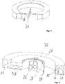
- Fig. 5 finally shows a cut cross-section of the double-walled tube 15, 15 'with the two partial tubes 22, 23, a partition 24, the fuel channel 7 and 7' seen in the direction of flow of the oxidizer.
- a lip 25 At the downstream end 26 there is a lip 25 for forming a recirculation zone 27 in the downstream direction at the burner mouth 28.
Landscapes
- Engineering & Computer Science (AREA)
- Chemical & Material Sciences (AREA)
- Combustion & Propulsion (AREA)
- Mechanical Engineering (AREA)
- General Engineering & Computer Science (AREA)
- Gas Burners (AREA)
Applications Claiming Priority (1)
| Application Number | Priority Date | Filing Date | Title |
|---|---|---|---|
| DE102019114954.1A DE102019114954A1 (de) | 2019-06-04 | 2019-06-04 | Brenner mit reduzierter Flammentemperatur und Stickoxidausstoß |
Publications (2)
| Publication Number | Publication Date |
|---|---|
| EP3748228A2 true EP3748228A2 (fr) | 2020-12-09 |
| EP3748228A3 EP3748228A3 (fr) | 2021-01-27 |
Family
ID=70977744
Family Applications (1)
| Application Number | Title | Priority Date | Filing Date |
|---|---|---|---|
| EP20178158.0A Withdrawn EP3748228A3 (fr) | 2019-06-04 | 2020-06-04 | Brûleur à température de flamme et émission d'oxydes d'azote réduites |
Country Status (2)
| Country | Link |
|---|---|
| EP (1) | EP3748228A3 (fr) |
| DE (1) | DE102019114954A1 (fr) |
Cited By (1)
| Publication number | Priority date | Publication date | Assignee | Title |
|---|---|---|---|---|
| CN113739151A (zh) * | 2021-08-16 | 2021-12-03 | 江苏大学 | 一种双管双向旋流燃烧器 |
Citations (2)
| Publication number | Priority date | Publication date | Assignee | Title |
|---|---|---|---|---|
| DE102017116529A1 (de) | 2017-07-21 | 2019-01-24 | Kueppers Solutions Gmbh | Brenner |
| DE102018112540A1 (de) | 2018-05-25 | 2019-11-28 | Kueppers Solutions Gmbh | Brennstoffdüsensystem |
Family Cites Families (5)
| Publication number | Priority date | Publication date | Assignee | Title |
|---|---|---|---|---|
| CA1170844A (fr) * | 1982-06-25 | 1984-07-17 | Carl E. Pearson | Systeme de carburant pour turbine a gaz |
| DE19503781A1 (de) * | 1995-02-04 | 1996-08-08 | Buderus Heiztechnik Gmbh | Öl- oder Gasgebläsebrenner |
| FR2776033B1 (fr) * | 1998-03-13 | 2000-08-18 | Gaz De France | Conditionneur d'ecoulement pour canalisation de transport de gaz |
| US8978383B2 (en) * | 2012-03-26 | 2015-03-17 | Pratt & Whitney Canada Corp. | Fuel manifold heat shield for a gas turbine engine |
| US20150316266A1 (en) * | 2014-04-30 | 2015-11-05 | Siemens Aktiengesellschaft | Burner with adjustable radial fuel profile |
-
2019
- 2019-06-04 DE DE102019114954.1A patent/DE102019114954A1/de active Pending
-
2020
- 2020-06-04 EP EP20178158.0A patent/EP3748228A3/fr not_active Withdrawn
Patent Citations (2)
| Publication number | Priority date | Publication date | Assignee | Title |
|---|---|---|---|---|
| DE102017116529A1 (de) | 2017-07-21 | 2019-01-24 | Kueppers Solutions Gmbh | Brenner |
| DE102018112540A1 (de) | 2018-05-25 | 2019-11-28 | Kueppers Solutions Gmbh | Brennstoffdüsensystem |
Cited By (2)
| Publication number | Priority date | Publication date | Assignee | Title |
|---|---|---|---|---|
| CN113739151A (zh) * | 2021-08-16 | 2021-12-03 | 江苏大学 | 一种双管双向旋流燃烧器 |
| CN113739151B (zh) * | 2021-08-16 | 2024-03-19 | 江苏大学 | 一种双管双向旋流燃烧器 |
Also Published As
| Publication number | Publication date |
|---|---|
| EP3748228A3 (fr) | 2021-01-27 |
| DE102019114954A1 (de) | 2020-12-10 |
Similar Documents
| Publication | Publication Date | Title |
|---|---|---|
| DE69515109T2 (de) | Verfahren und Vorrichtung zum Verbrennen sauerstoffhaltiger Bestandteile in einem Prozessgas | |
| DE60007946T2 (de) | Eine Brennkammer | |
| EP0741850B1 (fr) | Procede de combustion d'un combustible dans de l'air comprime | |
| DE19717721A1 (de) | Brennereinrichtung und Verfahren zum Betreiben einer Brennereinrichtung für eine NOx- und CO-arme Verbrennung | |
| DE4416650A1 (de) | Verbrennungsverfahren für atmosphärische Feuerungsanlagen | |
| WO1999037951A1 (fr) | Dispositif permettant de supprimer les oscillations de la flamme/pression dans un foyer, notamment une turbine a gaz | |
| DE2841637A1 (de) | Brenneranlage zum verbrennen gasfoermiger oder fluessiger brennstoffe | |
| WO1999004196A1 (fr) | Agencement de bruleurs pour une installation de chauffe, notamment une chambre de combustion de turbine a gaz | |
| EP3940293B1 (fr) | Procédé de combustion étagée d'un combustible et tête de combustion | |
| EP1561072A1 (fr) | Procede de combustion et tete de bruleur, bruleur pourvu d'une telle tete de bruleur et chaudiere de chauffage comportant une telle tete de bruleur | |
| DE60125892T2 (de) | Brennkammer | |
| DE4432395A1 (de) | Brennereinrichtung für einen gasartigen Brennstoff | |
| CH672366A5 (fr) | ||
| EP2037173B1 (fr) | Tête de brûleur et procédé de combustion à un étage de combustible dans une zone de combustion éloignée de la tête de brûleur | |
| DE2528559A1 (de) | Verfahren und vorrichtung zur durchfuehrung chemischer reaktionen zwischen fliessenden medien | |
| DE102015107360A1 (de) | Niedriges NOx -Verbrennungssystem für Wanderrostpelletierungsanlagen | |
| DE102019114954A1 (de) | Brenner mit reduzierter Flammentemperatur und Stickoxidausstoß | |
| EP3803210A1 (fr) | Système de buses de carburant | |
| AT406706B (de) | Brenner für gas- und ölheizkessel | |
| EP1754937B1 (fr) | Tête de brûleur et procédé pour brûler du combustible | |
| DE4008692A1 (de) | Mischeinrichtung fuer oelgeblaesebrenner | |
| EP0699867A2 (fr) | Dispositif de combustion pour combustibles gazeux | |
| DE19542644B4 (de) | Vormischverbrennung | |
| EP0864812A2 (fr) | Dispositif de mélange pour brûleur à gaz et à huile | |
| DE4408256A1 (de) | Verfahren und Vorrichtung zur Flammenstabilisation von Vormischbrennern |
Legal Events
| Date | Code | Title | Description |
|---|---|---|---|
| PUAI | Public reference made under article 153(3) epc to a published international application that has entered the european phase |
Free format text: ORIGINAL CODE: 0009012 |
|
| STAA | Information on the status of an ep patent application or granted ep patent |
Free format text: STATUS: THE APPLICATION HAS BEEN PUBLISHED |
|
| AK | Designated contracting states |
Kind code of ref document: A2 Designated state(s): AL AT BE BG CH CY CZ DE DK EE ES FI FR GB GR HR HU IE IS IT LI LT LU LV MC MK MT NL NO PL PT RO RS SE SI SK SM TR |
|
| AX | Request for extension of the european patent |
Extension state: BA ME |
|
| PUAL | Search report despatched |
Free format text: ORIGINAL CODE: 0009013 |
|
| AK | Designated contracting states |
Kind code of ref document: A3 Designated state(s): AL AT BE BG CH CY CZ DE DK EE ES FI FR GB GR HR HU IE IS IT LI LT LU LV MC MK MT NL NO PL PT RO RS SE SI SK SM TR |
|
| AX | Request for extension of the european patent |
Extension state: BA ME |
|
| RIC1 | Information provided on ipc code assigned before grant |
Ipc: F23D 14/58 20060101ALI20201221BHEP Ipc: F23D 17/00 20060101ALI20201221BHEP Ipc: F23D 14/24 20060101ALI20201221BHEP Ipc: F23D 11/38 20060101AFI20201221BHEP Ipc: F23D 14/70 20060101ALI20201221BHEP Ipc: F23D 11/40 20060101ALI20201221BHEP |
|
| STAA | Information on the status of an ep patent application or granted ep patent |
Free format text: STATUS: THE APPLICATION IS DEEMED TO BE WITHDRAWN |
|
| 18D | Application deemed to be withdrawn |
Effective date: 20210728 |