EP3748242B1 - Unité extérieure de climatiseur - Google Patents
Unité extérieure de climatiseur Download PDFInfo
- Publication number
- EP3748242B1 EP3748242B1 EP18903766.6A EP18903766A EP3748242B1 EP 3748242 B1 EP3748242 B1 EP 3748242B1 EP 18903766 A EP18903766 A EP 18903766A EP 3748242 B1 EP3748242 B1 EP 3748242B1
- Authority
- EP
- European Patent Office
- Prior art keywords
- panel
- machine
- chamber
- screw hole
- outdoor unit
- Prior art date
- Legal status (The legal status is an assumption and is not a legal conclusion. Google has not performed a legal analysis and makes no representation as to the accuracy of the status listed.)
- Active
Links
Images


Classifications
-
- F—MECHANICAL ENGINEERING; LIGHTING; HEATING; WEAPONS; BLASTING
- F24—HEATING; RANGES; VENTILATING
- F24F—AIR-CONDITIONING; AIR-HUMIDIFICATION; VENTILATION; USE OF AIR CURRENTS FOR SCREENING
- F24F1/00—Room units for air-conditioning, e.g. separate or self-contained units or units receiving primary air from a central station
- F24F1/06—Separate outdoor units, e.g. outdoor unit to be linked to a separate room comprising a compressor and a heat exchanger
- F24F1/56—Casing or covers of separate outdoor units, e.g. fan guards
-
- F—MECHANICAL ENGINEERING; LIGHTING; HEATING; WEAPONS; BLASTING
- F24—HEATING; RANGES; VENTILATING
- F24F—AIR-CONDITIONING; AIR-HUMIDIFICATION; VENTILATION; USE OF AIR CURRENTS FOR SCREENING
- F24F1/00—Room units for air-conditioning, e.g. separate or self-contained units or units receiving primary air from a central station
- F24F1/06—Separate outdoor units, e.g. outdoor unit to be linked to a separate room comprising a compressor and a heat exchanger
- F24F1/08—Compressors specially adapted for separate outdoor units
- F24F1/10—Arrangement or mounting thereof
-
- F—MECHANICAL ENGINEERING; LIGHTING; HEATING; WEAPONS; BLASTING
- F24—HEATING; RANGES; VENTILATING
- F24F—AIR-CONDITIONING; AIR-HUMIDIFICATION; VENTILATION; USE OF AIR CURRENTS FOR SCREENING
- F24F13/00—Details common to, or for air-conditioning, air-humidification, ventilation or use of air currents for screening
- F24F13/20—Casings or covers
- F24F2013/202—Mounting a compressor unit therein
Definitions
- the present disclosure relates to an outdoor unit for an air-conditioning apparatus, in which the outdoor unit includes a machine-chamber front panel forming a part of an outer box.
- Patent Literature 1 There is conventionally an outdoor unit for an air-conditioning apparatus, in which the outdoor unit includes a machine-chamber front panel forming a part of an outer box (for example, see Patent Literature 1).
- the machine-chamber front panel disclosed in Patent Literature 1 is designed to be removable from the outer box in consideration of serviceability.
- screw hole positions of the machine-chamber front panel are aligned with each other to screw the machine-chamber front panel to a top panel, the machine-chamber front panel is displaced downward by its own weight. This makes it difficult to align the screw hole positions with each other.
- Patent Literature 1 has a structure in consideration of workability, in which the top panel and the machine-chamber front panel are both provided with a temporary fixing portion at which the top panel and the machine-chamber front panel can be temporarily fixed to align their screw hole positions with each other.
- Patent Literature 1 Japanese Unexamined Patent Application Publication No. 2012-220127
- JP 2010 164221 A discloses an outdoor unit of an air conditioner with a top plate and a side plate, including the features of the preamble of the independent claim.
- a mechanical fixing strength is increased by bringing a folding back part of the top plate into contact with a projecting screw seat of the side plate. Additional technological background can be found in JP 2008 256296 A and JP 2009 097726 A .
- the top panel is formed with a groove-shaped portion as the temporary fixing portion.
- a groove-shaped portion as the temporary fixing portion.
- the appearance of this groove-shaped portion can be perceived as a dent, and makes the design unattractive.
- the outdoor unit of the present invention has been made to overcome the above problem, and aims to provide an outdoor unit for an air-conditioning apparatus that can minimize an unattractive design and can also maintain workability.
- An outdoor unit for an air-conditioning apparatus includes an outer box having a machine chamber formed therein in which a compressor is placed, wherein the outer box includes a machine-chamber front panel placed on a front side of the machine chamber and removable from the outer box, and a top panel to cover a top surface, in a front surface of the top panel, a top-panel screw hole into which a screw is inserted, and a curled portion having a shape curled toward an inner side at a lower end of the top panel are provided, on a front surface of the machine-chamber front panel, at an upper portion thereof, an insertion portion is formed and recessed backward, the insertion portion is provided with a front-panel screw hole into which a screw is inserted, and a protruding portion with a shape projecting toward a front side, and when the insertion portion is inserted inside a front surface of the top panel, and a position of the top-panel screw hole is aligned with a position of the front-panel screw hole, the pro
- the outdoor unit for an air-conditioning apparatus when the insertion portion is inserted inside the front surface of the top panel, and the position of the top-panel screw hole is aligned with the position of the front-panel screw hole, the protruding portion is engaged with the curled portion, so that the machine-chamber front panel can be temporarily fixed to the top panel.
- the curled portion has a shape curled toward the inner side of the top panel, and the protruding portion is positioned inside the front surface of the top panel.
- the outdoor unit can minimize the unattractive design and can also maintain workability.
- Fig. 1 is a perspective view of an outdoor unit 100 for an air-conditioning apparatus according to an embodiment of the present disclosure when viewed from the front top right side.
- Fig. 2 is a schematic plan view of the interior of the outdoor unit 100 for an air-conditioning apparatus according to the embodiment of the present disclosure.
- directional terms for example, “up,” “down,” “right,” “left,” “front,” and “rear,” may be used as appropriate. These directional terms are used herein solely for description purposes, and should not be construed to limit the scope of the disclosure of the present application. In the present embodiment, the directional terms, such as “up,” “down,” “right,” “left,” “front,” and “rear,” are used when the outdoor unit 100 is viewed from the front.
- the outdoor unit 100 for an air-conditioning apparatus includes a box-shaped outer box 1 constituting the outer casing as shown in Fig. 1 . Also as shown in Fig. 2 , the outdoor unit 100 includes a separator 10 to partition the interior of the outer box 1 into a fan chamber 10A and a machine chamber 10B.
- the fan chamber 10A is formed on the left of the interior of the outer box 1.
- an outdoor heat exchanger 5 to exchange heat between air and refrigerant, and a fan 4 to deliver air to the outdoor heat exchanger 5 are placed.
- the machine chamber 10B is formed on the right of the interior of the outer box 1.
- a compressor 2 to compress refrigerant
- an electrical component box (not shown) to accommodate therein various types of electrical components are placed.
- two fans 4 are provided in an up-and-down direction as shown in Fig. 1 .
- the number of the fans 4 is not limited thereto. At least one fan 4 may be provided.
- the outer box 1 includes a top panel 20 to cover a top surface, and a machine-chamber panel 30 to cover the machine chamber 10B formed on the right of the interior of the outer box 1.
- the machine-chamber panel 30 is made up of a machine-chamber front panel 31 to cover an upper portion of the machine-chamber front surface, and a forward upper portion of the machine-chamber right side, a lower machine-chamber front panel 32 to cover a lower portion of the machine-chamber front surface and a forward lower portion of the machine-chamber right side, a machine-chamber rear panel 33 to cover a rearward upper portion of the machine-chamber right side, and an upper portion of the machine-chamber back surface, and a lower machine-chamber rear panel 34 to cover a rearward lower portion of the machine-chamber right side and a lower portion of the machine-chamber back surface.
- the machine-chamber front panel 31 forms a part of the outer box 1, and is configured to be removable from the outer box 1.
- Fig. 3 is a cross-sectional schematic view of a temporary fixing portion and surroundings of the temporary fixing portion immediately before the machine-chamber front panel 31 of the outdoor unit 100 for an air-conditioning apparatus according to the embodiment of the present invention is mounted to the top panel 20. Note that Fig. 3 shows a part of the vertical cross section when the outdoor unit 100 is viewed from the right side.
- a top-panel screw hole 20b is formed, into which a fixing screw 7 (see Fig. 4 described later) is inserted.
- a curled portion 20a is provided at an end portion of the top panel 20 below the top-panel screw hole 20b.
- the curled portion 20a has a shape curled toward the inner side of the top panel 20.
- an insertion portion 40 is formed and recessed toward the back side.
- the insertion portion 40 is provided with a front-panel screw hole 40b, a protruding portion 40a, and preferably a recessed portion 40c.
- the screw 7 is inserted into the front-panel screw hole 40b.
- the protruding portion 40a is provided below the front-panel screw hole 40b, and has a shape projecting toward the front side to be engaged with the curled portion 20a of the top panel 20.
- the recessed portion 40c is provided below the protruding portion 40a, and has a shape recessed toward the back side to accommodate therein the curled portion 20a of the top panel 20.
- the temporary fixing portion of the outdoor unit 100 for an air-conditioning apparatus is made up of the curled portion 20a of the top panel 20, and the protruding portion 40a and the recessed portion 40c of the machine-chamber front panel 31.
- the protruding portion 40a, the front-panel screw hole 40b, and the recessed portion 40c of the machine-chamber front panel 31 are provided in the insertion portion 40 recessed toward the back side, and are positioned on the inner side of the outer box 1 relative to the other portion of the front surface of the machine-chamber front panel 31, that is, relative to the lower portion below the insertion portion 40.
- the top-panel screw hole 20b is provided above the curled portion 20a.
- the protruding portion 40a is provided below the front-panel screw hole 40b.
- the distance on the top panel 20 between the top-panel screw hole 20b and the curled portion 20a is approximately equal to the distance on the machine-chamber front panel 31 between the front-panel screw hole 40b and the recessed portion 40c.
- one protruding portion 40a is provided in the insertion portion 40.
- the configuration is not limited thereto, and two or more protruding portions 40a may be provided.
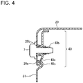
- Fig. 4 is a cross-sectional schematic view of the temporary fixing portion and surrounding of the temporary fixing portion in a state where the machine-chamber front panel 31 of the outdoor unit 100 for an air-conditioning apparatus according to the embodiment of the present invention is mounted to the outer box 1. Note that Fig. 4 shows a part of the vertical cross section when the outdoor unit 100 is viewed from the right side.
- the insertion portion 40 of the machine-chamber front panel 31 is moved upward to be inserted inside the front surface of the top panel 20.
- the position of the top-panel screw hole 20b is aligned with the position of the front-panel screw hole 40b in the up-and-down direction.
- the protruding portion 40a of the machine-chamber front panel 31 is engaged with the curled portion 20a of the top panel 20, and the curled portion 20a of the top panel 20 is accommodated in the recessed portion 40c of the machine-chamber front panel 31, so that the machine-chamber front panel 31 is temporarily fixed to the top panel 20.
- the machine-chamber front panel 31 is fixed to the top panel 20 with the screw 7.
- a groove-shaped portion is formed as a temporary fixing portion on a top panel. There is thus a problem in that the appearance of this groove-shaped portion can be perceived as a dent, and makes the design unattractive.
- the curled portion 20a is provided as the temporary fixing portion on the top panel 20.
- the curled portion 20a has a shape curled toward the inner side of the top panel 20.
- the protruding portion 40a and the recessed portion 40c of the machine-chamber front panel 31 are positioned inside the front surface of the top panel 20. That is, in the mounted state of the machine-chamber front panel 31 to the top panel 20, the temporary fixing portion can hardly be seen from outside. This can minimize the unattractive design of the outdoor unit 100 and can also maintain workability.
- an insertion portion is formed as a temporary fixing portion at an upper portion of a machine-chamber front panel.
- the insertion portion is pressed by a groove-shaped portion formed on the top panel and thus becomes deflected toward the back side, so that a reactive force against the pressing force brings the insertion portion into close contact with the inner side of the top panel to be temporarily fixed to the top panel.
- the insertion portion of the machine-chamber front panel is still deflected. The deflection caused by mounting the machine-chamber front panel to the top panel deforms a part of the insertion portion of the machine-chamber front panel. This leads to a problem that it is difficult to align the screw hole positions of the machine-chamber front panel and the top panel with each other, and this makes it difficult to screw the machine-chamber front panel to the top panel.
- the insertion portion 40 is provided with the protruding portion 40a, the front-panel screw hole 40b, and the recessed portion 40c of the machine-chamber front panel 31, and this insertion portion 40 is positioned on the inner side of the outer box 1 relative to the other portion of the front surface of the machine-chamber front panel 31.
- the protruding portion 40a of the machine-chamber front panel 31 is engaged with the curled portion 20a of the top panel 20, and the curled portion 20a of the top panel 20 is accommodated in the recessed portion 40c of the machine-chamber front panel 31, so that the machine-chamber front panel 31 is temporarily fixed to the top panel 20.
- the machine-chamber front panel 31 when the machine-chamber front panel 31 is temporarily fixed to the top panel 20, the curled portion 20a of the top panel 20 is accommodated in the recessed portion 40c. With this structure, at the time of the temporary fixing, a stress only acts on the protruding portion 40a. Thus, the machine-chamber front panel 31 and the top panel 20 can be screwed to each other in a state where such an external force as to deflect and deform the machine-chamber front panel 31 is hardly applied. That is, the machine-chamber front panel 31 and the top panel 20 can be screwed to each other without deforming the machine-chamber front panel 31.
- the distance on the top panel 20 between the top-panel screw hole 20b and the curled portion 20a is approximately equal to the distance on the machine-chamber front panel 31 between the front-panel screw hole 40b and the recessed portion 40c. It is thus easy to align the position of the top-panel screw hole 20b with the position of the front-panel screw hole 40b in the up-and-down direction, so that the machine-chamber front panel 31 and the top panel 20 can be easily screwed to each other.
- the outdoor unit 100 for an air-conditioning apparatus includes the outer box 1 having the machine chamber 10B formed therein to place the compressor 2 in the machine chamber 10B, wherein the outer box 1 includes the machine-chamber front panel 31 placed on the front side of the machine chamber 10B and removable from the outer box 1, and the top panel 20 to cover the top surface, and on the front surface of the top panel 20, the top-panel screw hole 20b into which the screw 7 is inserted, and the curled portion 20a having a shape curled toward the inner side at the lower end of the top panel 20 are provided, and on the front surface of the machine-chamber front panel 31, at the upper portion thereof, the insertion portion 40 is formed and recessed toward the back side, the insertion portion 40 is provided with the front-panel screw hole 40b into which the screw 7 is inserted, and the protruding portion 40a with a shape projecting toward the front side, and when the insertion portion 40 is inserted inside the front surface of the top panel 20, and the position of the top-panel screw hole 20b is align
- the outdoor unit 100 for an air-conditioning apparatus when the insertion portion 40 is inserted inside the front surface of the top panel 20, and the position of the top-panel screw hole 20b is aligned with the position of the front-panel screw hole 40b, the protruding portion 40a is engaged with the curled portion 20a, so that the machine-chamber front panel 31 can be temporarily fixed to the top panel 20.
- the curled portion 20a has a shape curled toward the inner side of the top panel 20, and the protruding portion 40a is positioned inside the front surface of the top panel 20.
- the outdoor unit 100 for an air-conditioning apparatus in which the outdoor unit 100 includes the machine-chamber front panel 31 removable from the outer box 1, can minimize the unattractive design and can also maintain workability.
- the insertion portion 40 is provided with the recessed portion 40c with a shape recessed toward the back side, the recessed portion 40c is provided below the protruding portion 40a, and when the insertion portion 40 is inserted inside the front surface of the top panel 20, and the position of the top-panel screw hole 20b is aligned with the position of the front-panel screw hole 40b, the curled portion 20a is accommodated in the recessed portion 40c.
- the machine-chamber front panel 31 when the machine-chamber front panel 31 is temporarily fixed to the top panel 20, the curled portion 20a of the top panel 20 is accommodated in the recessed portion 40c.
- a stress only acts on the protruding portion 40a.
- the machine-chamber front panel 31 and the top panel 20 can be screwed to each other in a state where such an external force as to deflect and deform the machine-chamber front panel 31 is not applied. That is, the machine-chamber front panel 31 and the top panel 20 can be screwed to each other without deforming the machine-chamber front panel 31.
Landscapes
- Engineering & Computer Science (AREA)
- Chemical & Material Sciences (AREA)
- Combustion & Propulsion (AREA)
- Mechanical Engineering (AREA)
- General Engineering & Computer Science (AREA)
- Other Air-Conditioning Systems (AREA)
Claims (3)
- Unité extérieure (100) pour un appareil de climatisation, l'unité extérieure (100) comprenant un boîtier extérieur (1) dans lequel est formée une chambre de machine (10B) dans laquelle est placé un compresseur, dans laquellele boîtier extérieur (1) inclutun panneau frontal de chambre de machine (31) placé sur un côté frontal de la chambre de machine (10B) et pouvant être retiré du boîtier extérieur (1), etun panneau supérieur (20) pour couvrir une surface supérieure,dans une surface avant du panneau supérieur (20), est ménagé un trou de vis de panneau supérieur (20b) dans lequel une vis (7) est insérée,sur une surface avant du panneau avant de la chambre de machine (31), au niveau d'une partie supérieure de celui-ci, une partie d'insertion (40) est formée et évidée vers l'arrière,la partie d'insertion (40) est pourvue d'un trou de vis de panneau avant (40b) dans lequel la vis (7) est insérée, caractérisée en ce quedans la surface avant du panneau supérieur (20), une partie incurvée (20a) présentant une forme incurvée vers un côté intérieur à une extrémité inférieure du panneau supérieur (20) est prévue,et en ce que la partie d'insertion (40) est pourvue d'une partie saillante (40a) avec une forme faisant saillie vers un côté avant par rapport au trou de vis de panneau avant (40b), eten outre en ce que lorsque la partie d'insertion (40) est insérée à l'intérieur d'une surface avant du panneau supérieur (20), et qu'une position du trou de vis de panneau supérieur (20b) est alignée avec une position du trou de vis de panneau avant (40b), la partie en saillie (40a) est mise en prise avec la partie incurvée (20a).
- Unité extérieure (100) pour un appareil de climatisation selon la revendication 1, dans laquellela partie d'insertion (40) est pourvue d'une partie évidée (40c) présentant une forme évidée vers l'arrière,la partie en creux (40c) est ménagée sous la partie en saillie (40a), etlorsque la partie d'insertion (40) est insérée à l'intérieur d'une surface avant du panneau supérieur (20), et qu'une position du trou de vis de panneau supérieur (20b) est alignée avec une position du trou de vis de panneau avant (40b), la partie incurvée (20a) est logée dans la partie en creux (40c).
- Unité extérieure (100) pour un appareil de climatisation selon la revendication 1 ou 2, dans laquelle la partie saillante (40a) est ménagée en dessous du trou de vis de panneau avant (40b).
Applications Claiming Priority (1)
| Application Number | Priority Date | Filing Date | Title |
|---|---|---|---|
| PCT/JP2018/002815 WO2019150413A1 (fr) | 2018-01-30 | 2018-01-30 | Unité extérieure de climatiseur |
Publications (3)
| Publication Number | Publication Date |
|---|---|
| EP3748242A1 EP3748242A1 (fr) | 2020-12-09 |
| EP3748242A4 EP3748242A4 (fr) | 2021-02-17 |
| EP3748242B1 true EP3748242B1 (fr) | 2022-10-05 |
Family
ID=67479163
Family Applications (1)
| Application Number | Title | Priority Date | Filing Date |
|---|---|---|---|
| EP18903766.6A Active EP3748242B1 (fr) | 2018-01-30 | 2018-01-30 | Unité extérieure de climatiseur |
Country Status (5)
| Country | Link |
|---|---|
| US (1) | US20200378629A1 (fr) |
| EP (1) | EP3748242B1 (fr) |
| JP (1) | JP7012750B2 (fr) |
| CN (1) | CN111656101A (fr) |
| WO (1) | WO2019150413A1 (fr) |
Families Citing this family (4)
| Publication number | Priority date | Publication date | Assignee | Title |
|---|---|---|---|---|
| USD1078003S1 (en) * | 2023-06-30 | 2025-06-03 | Rheem Manufacturing Company | Outdoor HVAC unit |
| USD1095781S1 (en) | 2023-06-30 | 2025-09-30 | Rheem Manufacturing Company | Outdoor HVAC unit |
| USD1095780S1 (en) | 2023-06-30 | 2025-09-30 | Rheem Manufacturing Company | Outdoor HVAC unit |
| US20250067447A1 (en) * | 2023-08-25 | 2025-02-27 | Rheem Manufacturing Company | Systems and methods for hvac outdoor unit with grill forming a support structure |
Family Cites Families (9)
| Publication number | Priority date | Publication date | Assignee | Title |
|---|---|---|---|---|
| JP2000161712A (ja) * | 1998-11-27 | 2000-06-16 | Matsushita Electric Ind Co Ltd | 分離型空気調和機の室外機 |
| JP2006258364A (ja) | 2005-03-17 | 2006-09-28 | Sanyo Electric Co Ltd | 分離型空気調和機の室外機 |
| JP2008256296A (ja) * | 2007-04-06 | 2008-10-23 | Matsushita Electric Ind Co Ltd | 空気調和機の室外機 |
| JP2009097726A (ja) * | 2007-10-12 | 2009-05-07 | Daikin Ind Ltd | 冷凍装置の室外ユニット |
| JP5131207B2 (ja) | 2009-01-14 | 2013-01-30 | パナソニック株式会社 | 空気調和機の室外ユニット |
| JP2012220127A (ja) | 2011-04-12 | 2012-11-12 | Panasonic Corp | 空気調和機の室外ユニット |
| CN103375900A (zh) * | 2012-04-18 | 2013-10-30 | 珠海格力电器股份有限公司 | 壳体定位结构及具有该壳体定位结构的空调装置 |
| JP2014126265A (ja) | 2012-12-26 | 2014-07-07 | Daikin Ind Ltd | 板材の接合構造及び接合方法 |
| CN104566685A (zh) * | 2014-12-25 | 2015-04-29 | 深圳创维空调科技有限公司 | 一种空调室外机及空调装置 |
-
2018
- 2018-01-30 CN CN201880087737.8A patent/CN111656101A/zh active Pending
- 2018-01-30 WO PCT/JP2018/002815 patent/WO2019150413A1/fr not_active Ceased
- 2018-01-30 EP EP18903766.6A patent/EP3748242B1/fr active Active
- 2018-01-30 US US16/771,266 patent/US20200378629A1/en not_active Abandoned
- 2018-01-30 JP JP2019568845A patent/JP7012750B2/ja active Active
Also Published As
| Publication number | Publication date |
|---|---|
| EP3748242A1 (fr) | 2020-12-09 |
| US20200378629A1 (en) | 2020-12-03 |
| EP3748242A4 (fr) | 2021-02-17 |
| JPWO2019150413A1 (ja) | 2020-11-19 |
| CN111656101A (zh) | 2020-09-11 |
| JP7012750B2 (ja) | 2022-01-28 |
| WO2019150413A1 (fr) | 2019-08-08 |
Similar Documents
| Publication | Publication Date | Title |
|---|---|---|
| EP3748242B1 (fr) | Unité extérieure de climatiseur | |
| CN105501163B (zh) | 用于将装饰部件定位在车辆上的结构 | |
| US20190219279A1 (en) | Outdoor unit for an air-conditioning apparatus | |
| EP0073073A1 (fr) | Cadre de montage muni d'entailles pour un appareil | |
| JP2016504771A (ja) | コントローラエンクロージャアセンブリ | |
| US11874003B2 (en) | Outdoor unit of air-conditioning apparatus | |
| US6780020B2 (en) | Structure for connecting instrument panel-side connector and vehicle body-side connector | |
| EP4459195A1 (fr) | Structure de maintien pour boîtier de composant électrique, unité extérieure et procédé de maintenance | |
| CN215675708U (zh) | 空调室内机的电控盒和空调室内机 | |
| JP3315863B2 (ja) | ワイヤーハーネスの真空成形型構造及びこの真空成形型構造を用いたワイヤーハーネスの真空成形方法 | |
| CN214852132U (zh) | 一种电控箱体及空气处理设备 | |
| US10246034B2 (en) | Power distribution center mounting assembly | |
| EP4058736B1 (fr) | Appareil ménager doté d'une porte | |
| WO2015163147A1 (fr) | Structure de montage de grille de conditionnement d'air et procédé de montage de grille de conditionnement d'air | |
| JP6827551B2 (ja) | 空気調和機の室外ユニット | |
| CN220017878U (zh) | 冰箱底板组件及具有其的冰箱 | |
| CN109282464B (zh) | 用于在空调柜的外箱中精确定位内箱的方法和空调柜 | |
| JP7112030B2 (ja) | 空気調和機の室外機 | |
| EP3982701A1 (fr) | Appareil électronique | |
| JP3822363B2 (ja) | 可動コネクタ | |
| CN206330226U (zh) | 冷冻循环装置的室外机 | |
| JP2020152304A (ja) | 分割部位締結構造及び車両用空調装置 | |
| CN104279730A (zh) | 一种显示盒结构 | |
| JP6531127B2 (ja) | 空気調和機 | |
| EP4492929A1 (fr) | Unité de commande et système de commande de direction |
Legal Events
| Date | Code | Title | Description |
|---|---|---|---|
| STAA | Information on the status of an ep patent application or granted ep patent |
Free format text: STATUS: THE INTERNATIONAL PUBLICATION HAS BEEN MADE |
|
| PUAI | Public reference made under article 153(3) epc to a published international application that has entered the european phase |
Free format text: ORIGINAL CODE: 0009012 |
|
| STAA | Information on the status of an ep patent application or granted ep patent |
Free format text: STATUS: REQUEST FOR EXAMINATION WAS MADE |
|
| 17P | Request for examination filed |
Effective date: 20200622 |
|
| AK | Designated contracting states |
Kind code of ref document: A1 Designated state(s): AL AT BE BG CH CY CZ DE DK EE ES FI FR GB GR HR HU IE IS IT LI LT LU LV MC MK MT NL NO PL PT RO RS SE SI SK SM TR |
|
| AX | Request for extension of the european patent |
Extension state: BA ME |
|
| A4 | Supplementary search report drawn up and despatched |
Effective date: 20210119 |
|
| RIC1 | Information provided on ipc code assigned before grant |
Ipc: F24F 1/56 20110101AFI20210113BHEP |
|
| DAV | Request for validation of the european patent (deleted) | ||
| DAX | Request for extension of the european patent (deleted) | ||
| GRAP | Despatch of communication of intention to grant a patent |
Free format text: ORIGINAL CODE: EPIDOSNIGR1 |
|
| STAA | Information on the status of an ep patent application or granted ep patent |
Free format text: STATUS: GRANT OF PATENT IS INTENDED |
|
| INTG | Intention to grant announced |
Effective date: 20220511 |
|
| GRAS | Grant fee paid |
Free format text: ORIGINAL CODE: EPIDOSNIGR3 |
|
| GRAA | (expected) grant |
Free format text: ORIGINAL CODE: 0009210 |
|
| STAA | Information on the status of an ep patent application or granted ep patent |
Free format text: STATUS: THE PATENT HAS BEEN GRANTED |
|
| AK | Designated contracting states |
Kind code of ref document: B1 Designated state(s): AL AT BE BG CH CY CZ DE DK EE ES FI FR GB GR HR HU IE IS IT LI LT LU LV MC MK MT NL NO PL PT RO RS SE SI SK SM TR |
|
| REG | Reference to a national code |
Ref country code: GB Ref legal event code: FG4D |
|
| REG | Reference to a national code |
Ref country code: CH Ref legal event code: EP |
|
| REG | Reference to a national code |
Ref country code: AT Ref legal event code: REF Ref document number: 1522952 Country of ref document: AT Kind code of ref document: T Effective date: 20221015 |
|
| REG | Reference to a national code |
Ref country code: IE Ref legal event code: FG4D |
|
| REG | Reference to a national code |
Ref country code: DE Ref legal event code: R096 Ref document number: 602018041569 Country of ref document: DE |
|
| REG | Reference to a national code |
Ref country code: LT Ref legal event code: MG9D |
|
| REG | Reference to a national code |
Ref country code: NL Ref legal event code: MP Effective date: 20221005 |
|
| REG | Reference to a national code |
Ref country code: AT Ref legal event code: MK05 Ref document number: 1522952 Country of ref document: AT Kind code of ref document: T Effective date: 20221005 |
|
| PG25 | Lapsed in a contracting state [announced via postgrant information from national office to epo] |
Ref country code: NL Free format text: LAPSE BECAUSE OF FAILURE TO SUBMIT A TRANSLATION OF THE DESCRIPTION OR TO PAY THE FEE WITHIN THE PRESCRIBED TIME-LIMIT Effective date: 20221005 |
|
| PG25 | Lapsed in a contracting state [announced via postgrant information from national office to epo] |
Ref country code: SE Free format text: LAPSE BECAUSE OF FAILURE TO SUBMIT A TRANSLATION OF THE DESCRIPTION OR TO PAY THE FEE WITHIN THE PRESCRIBED TIME-LIMIT Effective date: 20221005 Ref country code: PT Free format text: LAPSE BECAUSE OF FAILURE TO SUBMIT A TRANSLATION OF THE DESCRIPTION OR TO PAY THE FEE WITHIN THE PRESCRIBED TIME-LIMIT Effective date: 20230206 Ref country code: NO Free format text: LAPSE BECAUSE OF FAILURE TO SUBMIT A TRANSLATION OF THE DESCRIPTION OR TO PAY THE FEE WITHIN THE PRESCRIBED TIME-LIMIT Effective date: 20230105 Ref country code: LT Free format text: LAPSE BECAUSE OF FAILURE TO SUBMIT A TRANSLATION OF THE DESCRIPTION OR TO PAY THE FEE WITHIN THE PRESCRIBED TIME-LIMIT Effective date: 20221005 Ref country code: FI Free format text: LAPSE BECAUSE OF FAILURE TO SUBMIT A TRANSLATION OF THE DESCRIPTION OR TO PAY THE FEE WITHIN THE PRESCRIBED TIME-LIMIT Effective date: 20221005 Ref country code: ES Free format text: LAPSE BECAUSE OF FAILURE TO SUBMIT A TRANSLATION OF THE DESCRIPTION OR TO PAY THE FEE WITHIN THE PRESCRIBED TIME-LIMIT Effective date: 20221005 Ref country code: AT Free format text: LAPSE BECAUSE OF FAILURE TO SUBMIT A TRANSLATION OF THE DESCRIPTION OR TO PAY THE FEE WITHIN THE PRESCRIBED TIME-LIMIT Effective date: 20221005 |
|
| PG25 | Lapsed in a contracting state [announced via postgrant information from national office to epo] |
Ref country code: RS Free format text: LAPSE BECAUSE OF FAILURE TO SUBMIT A TRANSLATION OF THE DESCRIPTION OR TO PAY THE FEE WITHIN THE PRESCRIBED TIME-LIMIT Effective date: 20221005 Ref country code: PL Free format text: LAPSE BECAUSE OF FAILURE TO SUBMIT A TRANSLATION OF THE DESCRIPTION OR TO PAY THE FEE WITHIN THE PRESCRIBED TIME-LIMIT Effective date: 20221005 Ref country code: LV Free format text: LAPSE BECAUSE OF FAILURE TO SUBMIT A TRANSLATION OF THE DESCRIPTION OR TO PAY THE FEE WITHIN THE PRESCRIBED TIME-LIMIT Effective date: 20221005 Ref country code: IS Free format text: LAPSE BECAUSE OF FAILURE TO SUBMIT A TRANSLATION OF THE DESCRIPTION OR TO PAY THE FEE WITHIN THE PRESCRIBED TIME-LIMIT Effective date: 20230205 Ref country code: HR Free format text: LAPSE BECAUSE OF FAILURE TO SUBMIT A TRANSLATION OF THE DESCRIPTION OR TO PAY THE FEE WITHIN THE PRESCRIBED TIME-LIMIT Effective date: 20221005 Ref country code: GR Free format text: LAPSE BECAUSE OF FAILURE TO SUBMIT A TRANSLATION OF THE DESCRIPTION OR TO PAY THE FEE WITHIN THE PRESCRIBED TIME-LIMIT Effective date: 20230106 |
|
| P01 | Opt-out of the competence of the unified patent court (upc) registered |
Effective date: 20230512 |
|
| REG | Reference to a national code |
Ref country code: DE Ref legal event code: R097 Ref document number: 602018041569 Country of ref document: DE |
|
| PG25 | Lapsed in a contracting state [announced via postgrant information from national office to epo] |
Ref country code: SM Free format text: LAPSE BECAUSE OF FAILURE TO SUBMIT A TRANSLATION OF THE DESCRIPTION OR TO PAY THE FEE WITHIN THE PRESCRIBED TIME-LIMIT Effective date: 20221005 Ref country code: RO Free format text: LAPSE BECAUSE OF FAILURE TO SUBMIT A TRANSLATION OF THE DESCRIPTION OR TO PAY THE FEE WITHIN THE PRESCRIBED TIME-LIMIT Effective date: 20221005 Ref country code: EE Free format text: LAPSE BECAUSE OF FAILURE TO SUBMIT A TRANSLATION OF THE DESCRIPTION OR TO PAY THE FEE WITHIN THE PRESCRIBED TIME-LIMIT Effective date: 20221005 Ref country code: DK Free format text: LAPSE BECAUSE OF FAILURE TO SUBMIT A TRANSLATION OF THE DESCRIPTION OR TO PAY THE FEE WITHIN THE PRESCRIBED TIME-LIMIT Effective date: 20221005 Ref country code: CZ Free format text: LAPSE BECAUSE OF FAILURE TO SUBMIT A TRANSLATION OF THE DESCRIPTION OR TO PAY THE FEE WITHIN THE PRESCRIBED TIME-LIMIT Effective date: 20221005 |
|
| PLBE | No opposition filed within time limit |
Free format text: ORIGINAL CODE: 0009261 |
|
| STAA | Information on the status of an ep patent application or granted ep patent |
Free format text: STATUS: NO OPPOSITION FILED WITHIN TIME LIMIT |
|
| PG25 | Lapsed in a contracting state [announced via postgrant information from national office to epo] |
Ref country code: SK Free format text: LAPSE BECAUSE OF FAILURE TO SUBMIT A TRANSLATION OF THE DESCRIPTION OR TO PAY THE FEE WITHIN THE PRESCRIBED TIME-LIMIT Effective date: 20221005 Ref country code: AL Free format text: LAPSE BECAUSE OF FAILURE TO SUBMIT A TRANSLATION OF THE DESCRIPTION OR TO PAY THE FEE WITHIN THE PRESCRIBED TIME-LIMIT Effective date: 20221005 |
|
| REG | Reference to a national code |
Ref country code: CH Ref legal event code: PL |
|
| 26N | No opposition filed |
Effective date: 20230706 |
|
| PG25 | Lapsed in a contracting state [announced via postgrant information from national office to epo] |
Ref country code: LU Free format text: LAPSE BECAUSE OF NON-PAYMENT OF DUE FEES Effective date: 20230130 |
|
| REG | Reference to a national code |
Ref country code: BE Ref legal event code: MM Effective date: 20230131 |
|
| PG25 | Lapsed in a contracting state [announced via postgrant information from national office to epo] |
Ref country code: LI Free format text: LAPSE BECAUSE OF NON-PAYMENT OF DUE FEES Effective date: 20230131 Ref country code: CH Free format text: LAPSE BECAUSE OF NON-PAYMENT OF DUE FEES Effective date: 20230131 |
|
| PG25 | Lapsed in a contracting state [announced via postgrant information from national office to epo] |
Ref country code: SI Free format text: LAPSE BECAUSE OF FAILURE TO SUBMIT A TRANSLATION OF THE DESCRIPTION OR TO PAY THE FEE WITHIN THE PRESCRIBED TIME-LIMIT Effective date: 20221005 Ref country code: FR Free format text: LAPSE BECAUSE OF NON-PAYMENT OF DUE FEES Effective date: 20230131 Ref country code: BE Free format text: LAPSE BECAUSE OF NON-PAYMENT OF DUE FEES Effective date: 20230131 |
|
| PGFP | Annual fee paid to national office [announced via postgrant information from national office to epo] |
Ref country code: GB Payment date: 20231207 Year of fee payment: 7 |
|
| PG25 | Lapsed in a contracting state [announced via postgrant information from national office to epo] |
Ref country code: IE Free format text: LAPSE BECAUSE OF NON-PAYMENT OF DUE FEES Effective date: 20230130 |
|
| PGFP | Annual fee paid to national office [announced via postgrant information from national office to epo] |
Ref country code: DE Payment date: 20231205 Year of fee payment: 7 |
|
| PG25 | Lapsed in a contracting state [announced via postgrant information from national office to epo] |
Ref country code: IT Free format text: LAPSE BECAUSE OF FAILURE TO SUBMIT A TRANSLATION OF THE DESCRIPTION OR TO PAY THE FEE WITHIN THE PRESCRIBED TIME-LIMIT Effective date: 20221005 |
|
| PG25 | Lapsed in a contracting state [announced via postgrant information from national office to epo] |
Ref country code: MC Free format text: LAPSE BECAUSE OF FAILURE TO SUBMIT A TRANSLATION OF THE DESCRIPTION OR TO PAY THE FEE WITHIN THE PRESCRIBED TIME-LIMIT Effective date: 20221005 |
|
| PG25 | Lapsed in a contracting state [announced via postgrant information from national office to epo] |
Ref country code: MC Free format text: LAPSE BECAUSE OF FAILURE TO SUBMIT A TRANSLATION OF THE DESCRIPTION OR TO PAY THE FEE WITHIN THE PRESCRIBED TIME-LIMIT Effective date: 20221005 |
|
| PG25 | Lapsed in a contracting state [announced via postgrant information from national office to epo] |
Ref country code: BG Free format text: LAPSE BECAUSE OF FAILURE TO SUBMIT A TRANSLATION OF THE DESCRIPTION OR TO PAY THE FEE WITHIN THE PRESCRIBED TIME-LIMIT Effective date: 20221005 |
|
| PG25 | Lapsed in a contracting state [announced via postgrant information from national office to epo] |
Ref country code: BG Free format text: LAPSE BECAUSE OF FAILURE TO SUBMIT A TRANSLATION OF THE DESCRIPTION OR TO PAY THE FEE WITHIN THE PRESCRIBED TIME-LIMIT Effective date: 20221005 |
|
| PG25 | Lapsed in a contracting state [announced via postgrant information from national office to epo] |
Ref country code: CY Free format text: LAPSE BECAUSE OF FAILURE TO SUBMIT A TRANSLATION OF THE DESCRIPTION OR TO PAY THE FEE WITHIN THE PRESCRIBED TIME-LIMIT; INVALID AB INITIO Effective date: 20180130 |
|
| REG | Reference to a national code |
Ref country code: DE Ref legal event code: R119 Ref document number: 602018041569 Country of ref document: DE |
|
| PG25 | Lapsed in a contracting state [announced via postgrant information from national office to epo] |
Ref country code: HU Free format text: LAPSE BECAUSE OF FAILURE TO SUBMIT A TRANSLATION OF THE DESCRIPTION OR TO PAY THE FEE WITHIN THE PRESCRIBED TIME-LIMIT; INVALID AB INITIO Effective date: 20180130 |
|
| GBPC | Gb: european patent ceased through non-payment of renewal fee |
Effective date: 20250130 |
|
| PG25 | Lapsed in a contracting state [announced via postgrant information from national office to epo] |
Ref country code: DE Free format text: LAPSE BECAUSE OF NON-PAYMENT OF DUE FEES Effective date: 20250801 |
|
| PG25 | Lapsed in a contracting state [announced via postgrant information from national office to epo] |
Ref country code: GB Free format text: LAPSE BECAUSE OF NON-PAYMENT OF DUE FEES Effective date: 20250130 |
|
| PG25 | Lapsed in a contracting state [announced via postgrant information from national office to epo] |
Ref country code: TR Free format text: LAPSE BECAUSE OF FAILURE TO SUBMIT A TRANSLATION OF THE DESCRIPTION OR TO PAY THE FEE WITHIN THE PRESCRIBED TIME-LIMIT Effective date: 20221005 |