EP3748251A1 - Procédé et système de commande de structure de dissipation de chaleur de climatiseur - Google Patents
Procédé et système de commande de structure de dissipation de chaleur de climatiseur Download PDFInfo
- Publication number
- EP3748251A1 EP3748251A1 EP19747960.3A EP19747960A EP3748251A1 EP 3748251 A1 EP3748251 A1 EP 3748251A1 EP 19747960 A EP19747960 A EP 19747960A EP 3748251 A1 EP3748251 A1 EP 3748251A1
- Authority
- EP
- European Patent Office
- Prior art keywords
- deviation
- heat dissipation
- temperature
- refrigerant
- real
- Prior art date
- Legal status (The legal status is an assumption and is not a legal conclusion. Google has not performed a legal analysis and makes no representation as to the accuracy of the status listed.)
- Withdrawn
Links
Images


Classifications
-
- F—MECHANICAL ENGINEERING; LIGHTING; HEATING; WEAPONS; BLASTING
- F25—REFRIGERATION OR COOLING; COMBINED HEATING AND REFRIGERATION SYSTEMS; HEAT PUMP SYSTEMS; MANUFACTURE OR STORAGE OF ICE; LIQUEFACTION SOLIDIFICATION OF GASES
- F25B—REFRIGERATION MACHINES, PLANTS OR SYSTEMS; COMBINED HEATING AND REFRIGERATION SYSTEMS; HEAT PUMP SYSTEMS
- F25B41/00—Fluid-circulation arrangements
- F25B41/30—Expansion means; Dispositions thereof
- F25B41/31—Expansion valves
-
- F—MECHANICAL ENGINEERING; LIGHTING; HEATING; WEAPONS; BLASTING
- F24—HEATING; RANGES; VENTILATING
- F24F—AIR-CONDITIONING; AIR-HUMIDIFICATION; VENTILATION; USE OF AIR CURRENTS FOR SCREENING
- F24F13/00—Details common to, or for air-conditioning, air-humidification, ventilation or use of air currents for screening
- F24F13/30—Arrangement or mounting of heat-exchangers
-
- F—MECHANICAL ENGINEERING; LIGHTING; HEATING; WEAPONS; BLASTING
- F24—HEATING; RANGES; VENTILATING
- F24F—AIR-CONDITIONING; AIR-HUMIDIFICATION; VENTILATION; USE OF AIR CURRENTS FOR SCREENING
- F24F11/00—Control or safety arrangements
- F24F11/62—Control or safety arrangements characterised by the type of control or by internal processing, e.g. using fuzzy logic, adaptive control or estimation of values
- F24F11/63—Electronic processing
- F24F11/64—Electronic processing using pre-stored data
-
- F—MECHANICAL ENGINEERING; LIGHTING; HEATING; WEAPONS; BLASTING
- F24—HEATING; RANGES; VENTILATING
- F24F—AIR-CONDITIONING; AIR-HUMIDIFICATION; VENTILATION; USE OF AIR CURRENTS FOR SCREENING
- F24F11/00—Control or safety arrangements
- F24F11/70—Control systems characterised by their outputs; Constructional details thereof
- F24F11/80—Control systems characterised by their outputs; Constructional details thereof for controlling the temperature of the supplied air
- F24F11/83—Control systems characterised by their outputs; Constructional details thereof for controlling the temperature of the supplied air by controlling the supply of heat-exchange fluids to heat-exchangers
- F24F11/84—Control systems characterised by their outputs; Constructional details thereof for controlling the temperature of the supplied air by controlling the supply of heat-exchange fluids to heat-exchangers using valves
-
- F—MECHANICAL ENGINEERING; LIGHTING; HEATING; WEAPONS; BLASTING
- F24—HEATING; RANGES; VENTILATING
- F24F—AIR-CONDITIONING; AIR-HUMIDIFICATION; VENTILATION; USE OF AIR CURRENTS FOR SCREENING
- F24F11/00—Control or safety arrangements
- F24F11/88—Electrical aspects, e.g. circuits
-
- F—MECHANICAL ENGINEERING; LIGHTING; HEATING; WEAPONS; BLASTING
- F25—REFRIGERATION OR COOLING; COMBINED HEATING AND REFRIGERATION SYSTEMS; HEAT PUMP SYSTEMS; MANUFACTURE OR STORAGE OF ICE; LIQUEFACTION SOLIDIFICATION OF GASES
- F25B—REFRIGERATION MACHINES, PLANTS OR SYSTEMS; COMBINED HEATING AND REFRIGERATION SYSTEMS; HEAT PUMP SYSTEMS
- F25B41/00—Fluid-circulation arrangements
- F25B41/20—Disposition of valves, e.g. of on-off valves or flow control valves
-
- F—MECHANICAL ENGINEERING; LIGHTING; HEATING; WEAPONS; BLASTING
- F25—REFRIGERATION OR COOLING; COMBINED HEATING AND REFRIGERATION SYSTEMS; HEAT PUMP SYSTEMS; MANUFACTURE OR STORAGE OF ICE; LIQUEFACTION SOLIDIFICATION OF GASES
- F25B—REFRIGERATION MACHINES, PLANTS OR SYSTEMS; COMBINED HEATING AND REFRIGERATION SYSTEMS; HEAT PUMP SYSTEMS
- F25B41/00—Fluid-circulation arrangements
- F25B41/40—Fluid line arrangements
-
- F—MECHANICAL ENGINEERING; LIGHTING; HEATING; WEAPONS; BLASTING
- F25—REFRIGERATION OR COOLING; COMBINED HEATING AND REFRIGERATION SYSTEMS; HEAT PUMP SYSTEMS; MANUFACTURE OR STORAGE OF ICE; LIQUEFACTION SOLIDIFICATION OF GASES
- F25B—REFRIGERATION MACHINES, PLANTS OR SYSTEMS; COMBINED HEATING AND REFRIGERATION SYSTEMS; HEAT PUMP SYSTEMS
- F25B43/00—Arrangements for separating or purifying gases or liquids; Arrangements for vaporising the residuum of liquid refrigerant, e.g. by heat
-
- F—MECHANICAL ENGINEERING; LIGHTING; HEATING; WEAPONS; BLASTING
- F25—REFRIGERATION OR COOLING; COMBINED HEATING AND REFRIGERATION SYSTEMS; HEAT PUMP SYSTEMS; MANUFACTURE OR STORAGE OF ICE; LIQUEFACTION SOLIDIFICATION OF GASES
- F25B—REFRIGERATION MACHINES, PLANTS OR SYSTEMS; COMBINED HEATING AND REFRIGERATION SYSTEMS; HEAT PUMP SYSTEMS
- F25B49/00—Arrangement or mounting of control or safety devices
- F25B49/02—Arrangement or mounting of control or safety devices for compression type machines, plants or systems
-
- F—MECHANICAL ENGINEERING; LIGHTING; HEATING; WEAPONS; BLASTING
- F24—HEATING; RANGES; VENTILATING
- F24F—AIR-CONDITIONING; AIR-HUMIDIFICATION; VENTILATION; USE OF AIR CURRENTS FOR SCREENING
- F24F1/00—Room units for air-conditioning, e.g. separate or self-contained units or units receiving primary air from a central station
- F24F1/06—Separate outdoor units, e.g. outdoor unit to be linked to a separate room comprising a compressor and a heat exchanger
- F24F1/20—Electric components for separate outdoor units
- F24F1/24—Cooling of electric components
-
- F—MECHANICAL ENGINEERING; LIGHTING; HEATING; WEAPONS; BLASTING
- F24—HEATING; RANGES; VENTILATING
- F24F—AIR-CONDITIONING; AIR-HUMIDIFICATION; VENTILATION; USE OF AIR CURRENTS FOR SCREENING
- F24F11/00—Control or safety arrangements
- F24F11/50—Control or safety arrangements characterised by user interfaces or communication
- F24F11/61—Control or safety arrangements characterised by user interfaces or communication using timers
-
- F—MECHANICAL ENGINEERING; LIGHTING; HEATING; WEAPONS; BLASTING
- F24—HEATING; RANGES; VENTILATING
- F24F—AIR-CONDITIONING; AIR-HUMIDIFICATION; VENTILATION; USE OF AIR CURRENTS FOR SCREENING
- F24F2140/00—Control inputs relating to system states
- F24F2140/20—Heat-exchange fluid temperature
-
- F—MECHANICAL ENGINEERING; LIGHTING; HEATING; WEAPONS; BLASTING
- F25—REFRIGERATION OR COOLING; COMBINED HEATING AND REFRIGERATION SYSTEMS; HEAT PUMP SYSTEMS; MANUFACTURE OR STORAGE OF ICE; LIQUEFACTION SOLIDIFICATION OF GASES
- F25B—REFRIGERATION MACHINES, PLANTS OR SYSTEMS; COMBINED HEATING AND REFRIGERATION SYSTEMS; HEAT PUMP SYSTEMS
- F25B2400/00—Component parts or details not otherwise provided for in this subclass
- F25B2400/23—Separators
-
- F—MECHANICAL ENGINEERING; LIGHTING; HEATING; WEAPONS; BLASTING
- F25—REFRIGERATION OR COOLING; COMBINED HEATING AND REFRIGERATION SYSTEMS; HEAT PUMP SYSTEMS; MANUFACTURE OR STORAGE OF ICE; LIQUEFACTION SOLIDIFICATION OF GASES
- F25B—REFRIGERATION MACHINES, PLANTS OR SYSTEMS; COMBINED HEATING AND REFRIGERATION SYSTEMS; HEAT PUMP SYSTEMS
- F25B2600/00—Control issues
- F25B2600/25—Control of valves
- F25B2600/2513—Expansion valves
-
- F—MECHANICAL ENGINEERING; LIGHTING; HEATING; WEAPONS; BLASTING
- F25—REFRIGERATION OR COOLING; COMBINED HEATING AND REFRIGERATION SYSTEMS; HEAT PUMP SYSTEMS; MANUFACTURE OR STORAGE OF ICE; LIQUEFACTION SOLIDIFICATION OF GASES
- F25B—REFRIGERATION MACHINES, PLANTS OR SYSTEMS; COMBINED HEATING AND REFRIGERATION SYSTEMS; HEAT PUMP SYSTEMS
- F25B2700/00—Sensing or detecting of parameters; Sensors therefor
- F25B2700/21—Temperatures
-
- F—MECHANICAL ENGINEERING; LIGHTING; HEATING; WEAPONS; BLASTING
- F25—REFRIGERATION OR COOLING; COMBINED HEATING AND REFRIGERATION SYSTEMS; HEAT PUMP SYSTEMS; MANUFACTURE OR STORAGE OF ICE; LIQUEFACTION SOLIDIFICATION OF GASES
- F25B—REFRIGERATION MACHINES, PLANTS OR SYSTEMS; COMBINED HEATING AND REFRIGERATION SYSTEMS; HEAT PUMP SYSTEMS
- F25B41/00—Fluid-circulation arrangements
- F25B41/30—Expansion means; Dispositions thereof
- F25B41/31—Expansion valves
- F25B41/34—Expansion valves with the valve member being actuated by electric means, e.g. by piezoelectric actuators
-
- Y—GENERAL TAGGING OF NEW TECHNOLOGICAL DEVELOPMENTS; GENERAL TAGGING OF CROSS-SECTIONAL TECHNOLOGIES SPANNING OVER SEVERAL SECTIONS OF THE IPC; TECHNICAL SUBJECTS COVERED BY FORMER USPC CROSS-REFERENCE ART COLLECTIONS [XRACs] AND DIGESTS
- Y02—TECHNOLOGIES OR APPLICATIONS FOR MITIGATION OR ADAPTATION AGAINST CLIMATE CHANGE
- Y02B—CLIMATE CHANGE MITIGATION TECHNOLOGIES RELATED TO BUILDINGS, e.g. HOUSING, HOUSE APPLIANCES OR RELATED END-USER APPLICATIONS
- Y02B30/00—Energy efficient heating, ventilation or air conditioning [HVAC]
- Y02B30/70—Efficient control or regulation technologies, e.g. for control of refrigerant flow, motor or heating
Definitions
- the invention belongs to the technical field of air conditioning, and in particular relates to a method for controlling a heat dissipation structure of an air conditioner and a system for accomplishing the same.
- variable-speed air conditioners are widely used on the market due to their advantages of intelligence, high efficiency, low noise and quick adjustment of temperature.
- a variable speed air conditioner is provided with a control system and an inverter that enable a compressor therein to operate at several different speeds while running, thereby allowing the unit to run at the speed that best meets comfort needs.
- Some power components disposed within the inverter or in a control box where the main circuit board is installed are prone to overheating while working. If heat dissipation from those components in such a closed enclosure fails, the running of the compressor will probably be affected, and even over-temperature protection could be triggered to shut down the power supply of the compressor, and the rising temperatures also cause damages to the circuit components. Hence, the heat dissipation design for those power components is important.
- the first one is passive cooling which refers to the use of ventilation, such as horizontal slats formed onto the surface of the electric control box, to remove heat by the physical properties of air; and the second one is forced convection which generates an air flow by a cooling fan.
- the passive cooling has shortcomings in dust and water resistance so it is far from meeting the heat dissipation requirements of high power components; while in fact the cooling fan performs badly on heat dissipation effect and further has a limited service life which is shorter than that of the power components; once the cooling fan fails, it will damage the working stability of the inverter; but the improvement of the cooling fan may increase the cost of the product.
- One aspect of the present invention is to provide a method for controlling a heat dissipation structure of an air conditioner for solving the problems of poor heat dissipation reliability and high heat dissipation cost in the prior art.
- the larger the real-time temperature T e of the heat generating component, the smaller the correction value, and when T e ⁇ a second set temperature, the correction value is ⁇ 0; when a first set temperature ⁇ T e ⁇ the second set temperature, the correction value 0; when T e ⁇ the first set temperature, the correction value is >0.
- the correction value when 90°C ⁇ T e ⁇ 100°C, the correction value is -3°C; when 80°C ⁇ T e ⁇ 90°C, the correction value is -2°C; when 70°C ⁇ T e ⁇ 80°C, the correction value is -1°C; when 60°C ⁇ T e ⁇ 70°C, the correction value is 0; when 50°C ⁇ T e ⁇ 60°C, the correction value is 1°C; when 40°C ⁇ T e ⁇ 50°C, the correction value is 2°C.
- adjusting the opening degree of the electronic expansion valve based on the deviation ⁇ T deviation and the deviation change rate ⁇ T deviation includes:
- T max T e d + 5°C.
- the initial opening degree of the electronic expansion valve is in a range from 40% to 60% of a full opening degree.
- a solenoid valve SV2 is connected in series to the refrigerant heat dissipation pipe to close or open it.
- the refrigerant heat dissipation pipe is fixed to the heat generating component through a heat dissipation substrate, a thermal medium is coated on a contact surface between the heat dissipation substrate and the refrigerant heat dissipation pipe, and a thermal medium is also coated on a contact surface of the heat dissipation substrate and the heat generating component.
- Another aspect of the present invention is to provide a system for controlling a heat dissipation structure of an air conditioner, the heat dissipation structure including a refrigerant heat dissipation pipe and a heat dissipation substrate; wherein the heat generating component is fixed to the heat dissipation substrate and the refrigerant heat dissipation pipe is embedded in the heat dissipation substrate; on a contact surface of the heat dissipation substrate and the refrigerant heat dissipation pipe, a thermal medium is coated, and a thermal medium is also applied to a contact surface of the heat dissipation substrate 1 and the heat generating component; the inlet end of the refrigerant heat dissipation pipe is connected to the liquid pipe between the outdoor heat exchanger and the indoor heat exchanger, and the outlet end of the refrigerant heat dissipation pipe is connected to the liquid inlet pipe of the gas-liquid separator; the refrigerant heat dissipation pipe is provided with an
- a method for controlling a heat dissipation structure of an air conditioner and a system for accomplishing the same are disclosed aiming for improving heat dissipation reliability and reducing its cost in the prior art, and further to enable an air conditioner to run at a stable state.
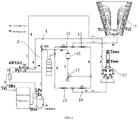
- FIG. 4 The structure of an air conditioner is shown in FIG. 4 .
- a refrigerant flow path of the air conditioner is: a compressor ⁇ an oil separator ⁇ a four-way valve (through a D-C channel) ⁇ an outdoor heat exchanger 11 (a fin-type condenser) ⁇ a check valve 15 ⁇ a liquid storage tank ⁇ a drying filter 13 ⁇ an electronic expansion valve 14 ⁇ a check valve 18 ⁇ an indoor heat exchanger 12 (a dry-type evaporator) ⁇ the four-way valve (through a E-S channel) ⁇ a gas-liquid separator ⁇ the compressor.
- a refrigerant flow path of the air conditioner is: the compressor ⁇ the oil separator ⁇ the four-way valve (through a D-E channel) ⁇ the indoor heat exchanger 12 (a dry-type evaporator) ⁇ a check valve 17 ⁇ the liquid storage tank ⁇ the drying filter 13 ⁇ the electronic expansion valve 14 ⁇ a check valve 16 ⁇ the outdoor heat exchanger 11 (a fin condenser) ⁇ the four-way valve (through a C-S channel) ⁇ the gas-liquid separator ⁇ the compressor.
- the heat dissipation structure provided by the present invention mainly comprises a refrigerant heat dissipation pipe 2.
- the refrigerant heat dissipation pipe 2 is fixed with a heat generating component 3, the inlet end of the refrigerant heat dissipation pipe 2 is connected to a liquid pipe between the outdoor heat exchanger and the indoor heat exchanger and the outlet end of the refrigerant heat dissipation pipe 2 is connected to an inlet pipe of the gas-liquid separator.
- An electronic expansion valve 4 is connected in series to the refrigerant heat dissipation pipe 2 for adjusting the flow rate of the refrigerant in the refrigerant heat dissipation pipe 2, as shown in FIG. 2 to FIG 4 .
- the inlet end of the refrigerant heat dissipation pipe 2 is specifically connected to an outlet end of the liquid storage tank, specifically to a portion of the refrigerant circulation before the electronic expansion valve 14 where the flow of refrigerant is not being controlled by the electronic expansion valve 14.
- Four check valves (15, 16, 17, and 18) are provided to maintain the refrigerant temperature in the refrigerant heat dissipation pipe 2 within a certain range in both cooling mode and heating mode.
- the refrigerant flowing out from the liquid storage tank is divided into two paths: in one path, the refrigerant flows to the drying filter 13 and the electronic expansion valve 14 to enter into a cooling cycle or a heating cycle of air conditioning, while in the other path, the refrigerant enters into the refrigerant heat dissipation pipe 2 to exchange heat with a heat generating component 3 and lower its temperature, and then flowing into the gas-liquid separator and the compressor sequentially.
- Those electronic components which could generate heat in an electric control box of the air conditioner could be regarded as a heat generating component, such as a frequency converter.
- the heat generated could be transferred to the refrigerant heat dissipation pipe 2 by heat conduction.
- a solenoid valve SV2 is also connected in series to the refrigerant heat dissipation pipe 2 so as to close or open it.
- the solenoid valve SV2 and the electronic expansion valve 4 are connected in series at the inlet end of the refrigerant heat dissipation pipe 2.
- the refrigerant heat dissipation pipe 2 is fixed to the heat generating component 3 through a heat dissipation substrate 1 to facilitate the fixing of the refrigerant heat dissipation pipe 2 and the heat generating component 3.
- the heat generating component 3 is fixedly connected to the thermal substrate 1 by bolts and the refrigerant heat dissipation pipe 2 is embedded in the thermal substrate 1.
- a thermal medium is coated on a contact surface between the heat dissipation substrate 1 and the refrigerant heat dissipation pipe 2, and a thermal medium is also coated on a contact surface of the heat dissipation substrate 1 and the heat generating component 3 to facilitate heat conduction and accelerate heat dissipation.
- the thermal medium could be silica gel which is good in thermal conductivity.
- the heat generated by the heat generating component 3 is transferred to the thermal substrate 1 and the thermal substrate 1 exchanges heat with the refrigerant in the refrigerant heat dissipation pipe 2. Hence, the heat generated by the heat generating component 3 is transferred to the refrigerant system by heat conduction to lower temperature of the heat generating component 3.
- the heat conduction path of the heat generating component is: the heat generating component 3 ⁇ the thermal substrate 1 ⁇ the refrigerant heat dissipation pipe 2.
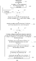
- FIG.1 shows a method for controlling the heat dissipation structure according to an embodiment of the present invention, which includes:
- Step S14 If T e ⁇ T e d , performing Step S14 because the temperature of the heat generating component is low and there is no need to use the refrigerant in the refrigerant heat dissipation pipe to lower its temperature.
- Step S15 If T e > T e d , performing Step S15 because the temperature of the heat generating component is high and it requires using the refrigerant in the refrigerant heat dissipation pipe to lower its temperature.
- Step S14 Closing the solenoid valve SV2 and the electronic expansion valve 4, and returning to Step S12.
- Step S15 Opening the solenoid valve SV2 and adjusting the electronic expansion valve 4 to a preset initial opening degree.
- the refrigerant flows into the refrigerant heat dissipation pipe, the gas-liquid separator, and the compressor sequentially.
- the refrigerant flowing in the refrigerant heat dissipation pipe exchanges heat with the heat generating component to cool the heat generating component.
- the initial opening degree of the electronic expansion valve 4 could be set in a range from 40% to 60% of the full opening degree. This range could avoid the rate of refrigerant flowing into the refrigerant heat dissipation pipe too small to worsen dissipation effect or too large to affect the refrigerant cycle of air conditioning, especially if it is too large it may further lead to a narrow adjustable range in Step S22 as follows.
- the initial opening degree is set to 50% of the full opening degree and it is an optimum value that not only achieves an ideal heat dissipation effect, but also avoids affecting the refrigerant cycle.
- the initial opening degree could be set in a range from 560 steps to 840 steps.
- the initial opening is set to 700 steps.
- Step S16 obtaining an update real-time temperature T e of the heat generating component after a preset time period.
- the electronic expansion valve 4 When the electronic expansion valve 4 is opened to the initial opening degree, it requires evaluating heat dissipation effect on the heat generating component after exchanging heat with the refrigerant in the refrigerant heat dissipation pipe, and therefore, it requires obtaining an update real-time temperature of the heat generating component.
- Step S17 determining whether or not the update real-time temperature T e > a preset upper limit value T max ; wherein T max > T e d .
- T max T e d + 5°C it suggests that the upper limit value T max is 5°C above the preset optimal temperature T e d .
- the value T max is set too small, the update real-time temperature T e may frequently be greater than T max ; the process may enter into Step S18 to Step S22 often to be cumbersome; if the value T max is set too large, the real-time temperature T e is probably less than T max ; the electronic expansion valve may not be timely adjusted even the heat generating component being overheated, the heat generating component may work in a overheated environment and burn out.
- T max T e d + 5°C is a reasonable value that not only ensures that the opening degree of the electronic expansion valve 4 could be timely adjusted when the heat generating component overheats, but also keeps the control process simple by avoiding entering into Step S18 to Step S22 frequently.
- Step 18 to Step 22 every set period of time, for example the set period of time could be 10 minutes.
- Step S18 Obtaining a refrigerant temperature refrigerant temperature T in at the inlet end of the refrigerant heat dissipation pipe and a refrigerant temperature T out at the outlet end of the refrigerant heat dissipation pipe.
- the correction of the target temperature difference according to the current real-time temperature T e enables the target temperature difference to be more accurate.
- it preferably sets that the larger the real-time temperature T e of the heat generating component, the smaller the correction value, and
- the correction value is determined according to the current real-time temperature T e of the heat generating component, and specifically includes:
- the above-mentioned correction of the preset target temperature difference according to the real-time temperature T e of the heat generating component can obtain a more accurate target temperature difference, thereby obtaining a more accurate deviation, thereby improving the accuracy of the opening adjustment of the electronic expansion valve 4.
- the deviation change rate indicates the variation of ⁇ T deviation , such as rising, declining, or constant.
- ⁇ T deviation' is the deviation calculated last time.
- Step S22 adjusting the opening degree of the electronic expansion valve based on the deviation ⁇ T deviation and the deviation change rate ⁇ T deviation .
- the adjustment of the opening degree of the electronic expansion valve 4 according to the deviation and the deviation change rate could further regulate the flow rate of the refrigerant flowing into the refrigerant heat dissipation pipe, thereby ensuring that the flow rate of the refrigerant is enough to exchange heat with the heat generating component to cool it and achieve better heat dissipation effect.
- the adjustment of the opening degree of the electronic expansion valve 4 is based on the deviation so that the temperature difference between the outlet end and the inlet end of the refrigerant heat dissipation pipe could reach the target temperature difference, thereby allowing heat from the heat generating component to be dissipated efficiently; the adjustment of the opening degree of the electronic expansion valve 4 is also based on the deviation change rate, namely taking into the variation trend of the deviation, so as to avoid frequent adjustments of the opening degree of the electronic expansion valve 4 and severe fluctuations of refrigerant flow rate that may affect normal cooling cycle or heating cycle. Therefore the stability of air conditioner is improved.
- heat from the heat generating component is transferred to the refrigerant and then transferred to the outside through it, thereby obtaining advantages of being energy-saving, reliable and low in cost.
- the operation of the heat generating component is ensured.
- Adjusting the opening degree of the electronic expansion valve 4 according to the deviation ⁇ T deviation and the deviation change rate ⁇ T deviation specifically includes:
- the ⁇ T deviation ⁇ -2°C it requires reducing the opening degree of the electronic expansion valve 4 because the difference between the refrigerant temperature difference and the target temperature difference is comparatively large although the deviation is still increasing.
- the ⁇ T deviation > 0 and the ⁇ T deviation is ⁇ 0 namely the refrigerant temperature difference between the outlet end and inlet end of the refrigerant heat dissipation pipe is greater than the target temperature difference, it suggests that the temperature of the heat generating component is comparatively high but the deviation is decreasing.
- the opening degree of the electronic expansion valve 4 is increased or decreased according to the specific value range of the deviation and the deviation change rate so that the temperature difference between the outlet end and the inlet end of the refrigerant heat dissipation pipe reaches to the target temperature differences. It ensures heat dissipation effect and avoids frequent adjustment of the opening degree of the electronic expansion valve 4 which may affect running stability.
- the electronic expansion valve 4 is reduced by 32 steps.
- the electronic expansion valve 4 is increased by 36 steps.
- the opening degree of the electronic expansion valve 4 is preferably adjusted based on those two factors: the deviation and the deviation change rate, hence for each time the steps of electronic expansion valve 4 could be increased or decreased on the basis of the previous opening degree otherwise the electronic expansion valve 4 requires returning to the initial opening degree repeatedly and then being adjusted.
- the method disclosed by the present embodiment is more convenient and stable.
- another embodiment of the present invention provides a system for controlling a heat dissipation structure of an air conditioner.
- the system includes including a heat dissipation structure and a control system.
- the heat dissipation structure includes a refrigerant heat dissipation pipe 2 and a heat dissipation substrate 1; wherein the heat generating component 3 is fixed to the heat dissipation substrate 1 and the refrigerant heat dissipation pipe 2 is embedded in the heat dissipation substrate 1; on a contact surface of the heat dissipation substrate 1 and the refrigerant heat dissipation pipe 2, a thermal medium is coated, and a thermal medium is also applied to a contact surface of the heat dissipation substrate 1 and the heat generating component 3.
- the inlet end of the refrigerant heat dissipation pipe 2 is connected to the liquid pipe between the outdoor heat exchanger and the indoor heat exchanger, and the outlet end of the refrigerant heat dissipation pipe 2 is connected to the liquid inlet pipe of the gas-liquid separator; the refrigerant heat dissipation pipe 2 is provided with an electronic expansion valve 4 and a solenoid valve SV2 connected with each other in series.
- the control system includes a heat generating component temperature acquisition module, a determination module, a refrigerant temperature acquisition module, a temperature difference calculation module, a correction module, a deviation calculation module, a deviation change rate calculation module and an opening adjustment module, as shown in FIG. 5 .
- the heat generating component temperature acquisition module is used to obtain the real-time temperature T e of the heat generating component.
- the determining module is configured to determine whether the real-time temperature T e > a preset optimal temperature T e d ; and is also configured to determine whether the real-time temperature T e > a preset upper limit value T max ; wherein T max > T e d .
- the refrigerant temperature obtaining module is configured to obtain a refrigerant temperature T in at an inlet end of the refrigerant heat dissipation pipe and a refrigerant temperature T out at the outlet end of the refrigerant heat dissipation pipe.
- the correction module is configured to determine a correction value according to the real-time temperature T e of the heat generating component and to correct the target temperature difference.
- the opening adjustment module is configured to adjust the opening of the electronic expansion valve to the initial opening degree, and is also configured to adjust the opening degree of the electronic expansion valve according to the deviation ⁇ T deviation and the deviation change rate ⁇ T deviation .
- the working process of the system for controlling a heat dissipation structure of an air conditioner could be referred to the method for controlling a heat dissipation structure of an air conditioner as described above.
Landscapes
- Engineering & Computer Science (AREA)
- Mechanical Engineering (AREA)
- General Engineering & Computer Science (AREA)
- Physics & Mathematics (AREA)
- Chemical & Material Sciences (AREA)
- Combustion & Propulsion (AREA)
- Thermal Sciences (AREA)
- Signal Processing (AREA)
- Fuzzy Systems (AREA)
- Mathematical Physics (AREA)
- Analytical Chemistry (AREA)
- Power Engineering (AREA)
- Air Conditioning Control Device (AREA)
Applications Claiming Priority (2)
| Application Number | Priority Date | Filing Date | Title |
|---|---|---|---|
| CN201810098748.8A CN108489069B (zh) | 2018-01-31 | 2018-01-31 | 一种空调散热结构控制方法及系统 |
| PCT/CN2019/073368 WO2019149167A1 (fr) | 2018-01-31 | 2019-01-28 | Procédé et système de commande de structure de dissipation de chaleur de climatiseur |
Publications (2)
| Publication Number | Publication Date |
|---|---|
| EP3748251A1 true EP3748251A1 (fr) | 2020-12-09 |
| EP3748251A4 EP3748251A4 (fr) | 2021-03-31 |
Family
ID=63344300
Family Applications (1)
| Application Number | Title | Priority Date | Filing Date |
|---|---|---|---|
| EP19747960.3A Withdrawn EP3748251A4 (fr) | 2018-01-31 | 2019-01-28 | Procédé et système de commande de structure de dissipation de chaleur de climatiseur |
Country Status (4)
| Country | Link |
|---|---|
| US (1) | US11530855B2 (fr) |
| EP (1) | EP3748251A4 (fr) |
| CN (1) | CN108489069B (fr) |
| WO (1) | WO2019149167A1 (fr) |
Families Citing this family (23)
| Publication number | Priority date | Publication date | Assignee | Title |
|---|---|---|---|---|
| WO2017027716A1 (fr) * | 2015-08-11 | 2017-02-16 | Trane International Inc. | Récupération et réhabilitation de réfrigérant |
| CN108489069B (zh) * | 2018-01-31 | 2020-08-18 | 青岛海尔空调电子有限公司 | 一种空调散热结构控制方法及系统 |
| CN108759008B (zh) * | 2018-06-12 | 2020-09-04 | 广东美的暖通设备有限公司 | 空调的控制方法、装置及具有其的空调 |
| CN109114839A (zh) * | 2018-10-22 | 2019-01-01 | 珠海格力电器股份有限公司 | 空调系统 |
| CN110793151B (zh) * | 2019-11-19 | 2021-08-27 | 宁波奥克斯电气股份有限公司 | 一种多联机冷媒控制方法、装置、空调器及存储介质 |
| CN111780369B (zh) * | 2020-06-30 | 2022-01-21 | 青岛海尔空调器有限总公司 | 用于空调高温除菌控制的方法及装置、空调 |
| CN111795474B (zh) * | 2020-07-17 | 2021-11-23 | 广东Tcl智能暖通设备有限公司 | 空调器的控制方法、控制装置、空调器及存储介质 |
| CN112303853B (zh) * | 2020-10-30 | 2023-02-03 | 青岛海尔空调电子有限公司 | 吸风式空调器的控制方法 |
| CN112413937B (zh) * | 2020-11-23 | 2022-05-31 | 珠海格力电器股份有限公司 | 冷水机组及其电子膨胀阀控制方法、装置、系统 |
| CN112566464B (zh) * | 2020-12-10 | 2022-04-12 | 青岛海信日立空调系统有限公司 | 一种空调器 |
| CN113310257A (zh) * | 2021-06-02 | 2021-08-27 | 广东纽恩泰新能源科技发展有限公司 | 一种热泵出水温度的控制方法 |
| CN114810321A (zh) * | 2021-06-30 | 2022-07-29 | 长城汽车股份有限公司 | 一种具有tmm的发动机的冷却液温度控制方法、装置及车辆 |
| CN113503585A (zh) * | 2021-07-13 | 2021-10-15 | 北京突破智能科技有限公司 | 一种新型节能空调系统 |
| CN113710078B (zh) * | 2021-10-29 | 2022-02-08 | 天津飞旋科技股份有限公司 | 一种变频器的散热方法和散热系统 |
| CN114110913B (zh) * | 2021-11-09 | 2022-12-13 | 珠海格力电器股份有限公司 | 空调系统及其防凝露控制方法、装置、存储介质及处理器 |
| CN114489174B (zh) * | 2021-12-28 | 2023-03-07 | 中国航天空气动力技术研究院 | 基于链式自控策略的汽车环境风洞温度控制系统 |
| CN116489934A (zh) * | 2022-01-13 | 2023-07-25 | 麦克维尔空调制冷(武汉)有限公司 | 用于冷水机组的变频柜冷却装置、变频柜及方法 |
| CN114543327B (zh) * | 2022-01-17 | 2024-06-18 | 青岛海尔空调器有限总公司 | 用于确定膨胀阀开度的方法、装置、空调器和存储介质 |
| CN117006741B (zh) * | 2022-04-29 | 2025-10-31 | 广东美的制冷设备有限公司 | 换热器、换热器的流路控制方法、可读存储介质及空调器 |
| CN116907045A (zh) * | 2023-07-10 | 2023-10-20 | 珠海格力电器股份有限公司 | 一种空调散热控制方法、装置及空调机组 |
| CN117529065A (zh) * | 2024-01-04 | 2024-02-06 | 浙江飞旋科技有限公司 | 一种控制方法、装置、冷却系统、变频器及变频机组 |
| CN119687615B (zh) * | 2024-12-18 | 2025-11-28 | 珠海格力电器股份有限公司 | 集成式压缩机及其控制方法、装置、存储介质和程序产品 |
| CN120321927B (zh) * | 2025-06-19 | 2025-08-22 | 华东交通大学 | 一种浸没式液冷冷却装置、控制方法及系统 |
Family Cites Families (16)
| Publication number | Priority date | Publication date | Assignee | Title |
|---|---|---|---|---|
| JP2909190B2 (ja) * | 1990-11-02 | 1999-06-23 | 株式会社東芝 | 空気調和機 |
| JPH08189719A (ja) | 1995-01-12 | 1996-07-23 | Mitsubishi Electric Corp | 空気調和装置 |
| JPH08247523A (ja) * | 1995-03-13 | 1996-09-27 | Yanmar Diesel Engine Co Ltd | 空調装置 |
| JP2008057875A (ja) | 2006-08-31 | 2008-03-13 | Mitsubishi Electric Corp | 冷凍サイクル装置 |
| CN102954555B (zh) * | 2011-08-22 | 2014-09-10 | 浙江三花股份有限公司 | 一种控制膨胀阀开度的方法 |
| US20130255932A1 (en) | 2012-03-30 | 2013-10-03 | Emerson Climate Technologies, Inc. | Heat sink for a condensing unit and method of using same |
| CN104566840B (zh) * | 2013-10-16 | 2018-04-27 | 海尔集团公司 | 冷媒散热装置、安装其的空调及温度控制方法 |
| CN104848438A (zh) * | 2015-05-20 | 2015-08-19 | 广东志高暖通设备股份有限公司 | 变频空调及空调室外机散热装置 |
| CN104964345A (zh) * | 2015-06-25 | 2015-10-07 | 广东美的制冷设备有限公司 | 空调室内机及具有其的空调器 |
| JP2017141987A (ja) * | 2016-02-08 | 2017-08-17 | 三菱重工業株式会社 | 冷凍サイクル装置 |
| CN106052216B (zh) * | 2016-06-29 | 2018-05-29 | 宁波奥克斯电气股份有限公司 | 一种多联机制热时对电子膨胀阀的控制方法 |
| CN106288032A (zh) * | 2016-08-12 | 2017-01-04 | 青岛海尔空调器有限总公司 | 一种利用双回气压缩机降低变频板芯片温升的方法和空调 |
| CN206207598U (zh) | 2016-10-11 | 2017-05-31 | 青岛海尔智能技术研发有限公司 | 空调器 |
| CN107355914B (zh) * | 2017-06-15 | 2020-07-07 | 青岛海尔空调电子有限公司 | 一种空调散热结构参数确定方法及空调散热结构 |
| CN108489069B (zh) * | 2018-01-31 | 2020-08-18 | 青岛海尔空调电子有限公司 | 一种空调散热结构控制方法及系统 |
| CN109000392A (zh) * | 2018-08-27 | 2018-12-14 | 珠海格力电器股份有限公司 | 一种空调冷水机组的变频器冷却方法、空调冷水机组及空调 |
-
2018
- 2018-01-31 CN CN201810098748.8A patent/CN108489069B/zh active Active
-
2019
- 2019-01-28 US US16/966,693 patent/US11530855B2/en active Active
- 2019-01-28 EP EP19747960.3A patent/EP3748251A4/fr not_active Withdrawn
- 2019-01-28 WO PCT/CN2019/073368 patent/WO2019149167A1/fr not_active Ceased
Also Published As
| Publication number | Publication date |
|---|---|
| EP3748251A4 (fr) | 2021-03-31 |
| CN108489069A (zh) | 2018-09-04 |
| US11530855B2 (en) | 2022-12-20 |
| CN108489069B (zh) | 2020-08-18 |
| WO2019149167A1 (fr) | 2019-08-08 |
| US20210033321A1 (en) | 2021-02-04 |
Similar Documents
| Publication | Publication Date | Title |
|---|---|---|
| US11530855B2 (en) | Air conditioner heat dissipation structure control method and system | |
| KR102329030B1 (ko) | 자연냉각 기계실 에어컨의 제어 방법, 제어 장치 및 자연냉각 기계실 에어컨 | |
| CN104374036B (zh) | 空调的控制方法和空调机组 | |
| CN106765915B (zh) | 空调节能控制方法 | |
| CN106765890B (zh) | 用于空调控制的方法及空调 | |
| CN106594988B (zh) | 空调节能控制方法 | |
| CN107631436B (zh) | 多联式空调器在制冷工况下的控制方法及系统 | |
| CN106969547B (zh) | 蒸发器冷媒流量分配控制方法和控制装置以及空调器系统 | |
| CN106765563A (zh) | 空调节能控制方法 | |
| JP4594276B2 (ja) | 冷温熱源機の冷温水制御方法及びこれに用いる空調システム | |
| WO2021063088A1 (fr) | Système et procédé de refroidissement pour onduleur, et appareil de climatisation | |
| CN110736277A (zh) | 风冷热泵系统的自适应除霜控制方法 | |
| WO2019034124A1 (fr) | Procédé de commande de climatiseur à réglage automatique de température et climatiseur associé | |
| CN116123638A (zh) | 一种热泵空调器及其运转控制方法 | |
| CN107477798B (zh) | 用于控制空调的冷媒的方法和装置、空调 | |
| CN106765912A (zh) | 定频空调停机控制方法 | |
| CN112146260B (zh) | 用于空调防凝露的方法、装置和空调 | |
| CN107270583A (zh) | 热泵机组的控制方法 | |
| CN106765908B (zh) | 空调节能控制方法 | |
| CN117015220A (zh) | 液冷设备及其防凝露控制方法 | |
| CN107289696A (zh) | 节流阀的控制方法 | |
| CN208886990U (zh) | 一种冷冻水恒温装置 | |
| CN106594987A (zh) | 定频空调停机控制方法 | |
| CN112566464B (zh) | 一种空调器 | |
| KR100826926B1 (ko) | 수냉식 공기조화기 및 그 제어방법 |
Legal Events
| Date | Code | Title | Description |
|---|---|---|---|
| STAA | Information on the status of an ep patent application or granted ep patent |
Free format text: STATUS: THE INTERNATIONAL PUBLICATION HAS BEEN MADE |
|
| PUAI | Public reference made under article 153(3) epc to a published international application that has entered the european phase |
Free format text: ORIGINAL CODE: 0009012 |
|
| STAA | Information on the status of an ep patent application or granted ep patent |
Free format text: STATUS: REQUEST FOR EXAMINATION WAS MADE |
|
| 17P | Request for examination filed |
Effective date: 20200806 |
|
| AK | Designated contracting states |
Kind code of ref document: A1 Designated state(s): AL AT BE BG CH CY CZ DE DK EE ES FI FR GB GR HR HU IE IS IT LI LT LU LV MC MK MT NL NO PL PT RO RS SE SI SK SM TR |
|
| AX | Request for extension of the european patent |
Extension state: BA ME |
|
| A4 | Supplementary search report drawn up and despatched |
Effective date: 20210226 |
|
| RIC1 | Information provided on ipc code assigned before grant |
Ipc: F24F 11/88 20180101ALI20210222BHEP Ipc: F24F 11/84 20180101ALI20210222BHEP Ipc: F24F 1/24 20110101ALI20210222BHEP Ipc: F24F 140/20 20180101ALI20210222BHEP Ipc: F24F 13/30 20060101AFI20210222BHEP Ipc: F24F 11/64 20180101ALI20210222BHEP |
|
| DAV | Request for validation of the european patent (deleted) | ||
| DAX | Request for extension of the european patent (deleted) | ||
| STAA | Information on the status of an ep patent application or granted ep patent |
Free format text: STATUS: THE APPLICATION IS DEEMED TO BE WITHDRAWN |
|
| 18D | Application deemed to be withdrawn |
Effective date: 20210928 |