EP3748317A1 - Verfahren und vorrichtung zur erfassung von räumlich aufgelösten spektralinformationen - Google Patents
Verfahren und vorrichtung zur erfassung von räumlich aufgelösten spektralinformationen Download PDFInfo
- Publication number
- EP3748317A1 EP3748317A1 EP19178381.0A EP19178381A EP3748317A1 EP 3748317 A1 EP3748317 A1 EP 3748317A1 EP 19178381 A EP19178381 A EP 19178381A EP 3748317 A1 EP3748317 A1 EP 3748317A1
- Authority
- EP
- European Patent Office
- Prior art keywords
- image
- target
- image line
- optical element
- orientation
- Prior art date
- Legal status (The legal status is an assumption and is not a legal conclusion. Google has not performed a legal analysis and makes no representation as to the accuracy of the status listed.)
- Withdrawn
Links
- 230000003595 spectral effect Effects 0.000 title claims abstract description 68
- 238000000034 method Methods 0.000 title claims abstract description 43
- 230000003287 optical effect Effects 0.000 claims abstract description 141
- 238000001228 spectrum Methods 0.000 claims abstract description 52
- 230000001902 propagating effect Effects 0.000 claims abstract description 5
- 238000011156 evaluation Methods 0.000 claims description 21
- 230000005540 biological transmission Effects 0.000 claims description 14
- 238000005192 partition Methods 0.000 claims description 8
- 238000000701 chemical imaging Methods 0.000 abstract description 13
- 230000008859 change Effects 0.000 abstract description 5
- 238000003384 imaging method Methods 0.000 description 10
- 238000001514 detection method Methods 0.000 description 6
- 238000005286 illumination Methods 0.000 description 6
- 238000012544 monitoring process Methods 0.000 description 6
- 238000012545 processing Methods 0.000 description 6
- 241000196324 Embryophyta Species 0.000 description 5
- 238000013459 approach Methods 0.000 description 4
- 230000008901 benefit Effects 0.000 description 4
- 238000004611 spectroscopical analysis Methods 0.000 description 4
- 239000000126 substance Substances 0.000 description 4
- 235000013305 food Nutrition 0.000 description 3
- 241000894006 Bacteria Species 0.000 description 2
- 238000004590 computer program Methods 0.000 description 2
- 230000001419 dependent effect Effects 0.000 description 2
- 230000001066 destructive effect Effects 0.000 description 2
- 230000000694 effects Effects 0.000 description 2
- 238000000605 extraction Methods 0.000 description 2
- 230000014509 gene expression Effects 0.000 description 2
- 229910052736 halogen Inorganic materials 0.000 description 2
- 230000000737 periodic effect Effects 0.000 description 2
- 238000007781 pre-processing Methods 0.000 description 2
- 238000012418 validation experiment Methods 0.000 description 2
- 241000972773 Aulopiformes Species 0.000 description 1
- 241000588724 Escherichia coli Species 0.000 description 1
- 229910000530 Gallium indium arsenide Inorganic materials 0.000 description 1
- 229910000661 Mercury cadmium telluride Inorganic materials 0.000 description 1
- 206010028980 Neoplasm Diseases 0.000 description 1
- 241000607142 Salmonella Species 0.000 description 1
- 241001464837 Viridiplantae Species 0.000 description 1
- 239000013566 allergen Substances 0.000 description 1
- 238000004458 analytical method Methods 0.000 description 1
- 238000003491 array Methods 0.000 description 1
- 201000011510 cancer Diseases 0.000 description 1
- 229930002875 chlorophyll Natural products 0.000 description 1
- 235000019804 chlorophyll Nutrition 0.000 description 1
- ATNHDLDRLWWWCB-AENOIHSZSA-M chlorophyll a Chemical compound C1([C@@H](C(=O)OC)C(=O)C2=C3C)=C2N2C3=CC(C(CC)=C3C)=[N+]4C3=CC3=C(C=C)C(C)=C5N3[Mg-2]42[N+]2=C1[C@@H](CCC(=O)OC\C=C(/C)CCC[C@H](C)CCC[C@H](C)CCCC(C)C)[C@H](C)C2=C5 ATNHDLDRLWWWCB-AENOIHSZSA-M 0.000 description 1
- 238000013500 data storage Methods 0.000 description 1
- 208000002925 dental caries Diseases 0.000 description 1
- 238000011161 development Methods 0.000 description 1
- 238000003745 diagnosis Methods 0.000 description 1
- 201000010099 disease Diseases 0.000 description 1
- 208000037265 diseases, disorders, signs and symptoms Diseases 0.000 description 1
- 230000005670 electromagnetic radiation Effects 0.000 description 1
- 230000007613 environmental effect Effects 0.000 description 1
- 239000003344 environmental pollutant Substances 0.000 description 1
- 238000002474 experimental method Methods 0.000 description 1
- 239000002360 explosive Substances 0.000 description 1
- 150000002367 halogens Chemical class 0.000 description 1
- 230000003862 health status Effects 0.000 description 1
- WPYVAWXEWQSOGY-UHFFFAOYSA-N indium antimonide Chemical compound [Sb]#[In] WPYVAWXEWQSOGY-UHFFFAOYSA-N 0.000 description 1
- 238000003331 infrared imaging Methods 0.000 description 1
- 230000002401 inhibitory effect Effects 0.000 description 1
- 238000007689 inspection Methods 0.000 description 1
- 208000028867 ischemia Diseases 0.000 description 1
- 239000000463 material Substances 0.000 description 1
- 235000013372 meat Nutrition 0.000 description 1
- 239000004081 narcotic agent Substances 0.000 description 1
- 230000035515 penetration Effects 0.000 description 1
- 231100000719 pollutant Toxicity 0.000 description 1
- 238000001303 quality assessment method Methods 0.000 description 1
- 239000010453 quartz Substances 0.000 description 1
- 239000002994 raw material Substances 0.000 description 1
- 230000004044 response Effects 0.000 description 1
- 235000019515 salmon Nutrition 0.000 description 1
- VYPSYNLAJGMNEJ-UHFFFAOYSA-N silicon dioxide Inorganic materials O=[Si]=O VYPSYNLAJGMNEJ-UHFFFAOYSA-N 0.000 description 1
- 230000009466 transformation Effects 0.000 description 1
- 229910052721 tungsten Inorganic materials 0.000 description 1
- 239000010937 tungsten Substances 0.000 description 1
- -1 tungsten halogen Chemical class 0.000 description 1
- 238000010200 validation analysis Methods 0.000 description 1
Images


Classifications
-
- G—PHYSICS
- G01—MEASURING; TESTING
- G01J—MEASUREMENT OF INTENSITY, VELOCITY, SPECTRAL CONTENT, POLARISATION, PHASE OR PULSE CHARACTERISTICS OF INFRARED, VISIBLE OR ULTRAVIOLET LIGHT; COLORIMETRY; RADIATION PYROMETRY
- G01J3/00—Spectrometry; Spectrophotometry; Monochromators; Measuring colours
- G01J3/02—Details
- G01J3/0205—Optical elements not provided otherwise, e.g. optical manifolds, diffusers, windows
- G01J3/0229—Optical elements not provided otherwise, e.g. optical manifolds, diffusers, windows using masks, aperture plates, spatial light modulators or spatial filters, e.g. reflective filters
-
- G—PHYSICS
- G01—MEASURING; TESTING
- G01J—MEASUREMENT OF INTENSITY, VELOCITY, SPECTRAL CONTENT, POLARISATION, PHASE OR PULSE CHARACTERISTICS OF INFRARED, VISIBLE OR ULTRAVIOLET LIGHT; COLORIMETRY; RADIATION PYROMETRY
- G01J3/00—Spectrometry; Spectrophotometry; Monochromators; Measuring colours
- G01J3/02—Details
- G01J3/0205—Optical elements not provided otherwise, e.g. optical manifolds, diffusers, windows
-
- G—PHYSICS
- G01—MEASURING; TESTING
- G01J—MEASUREMENT OF INTENSITY, VELOCITY, SPECTRAL CONTENT, POLARISATION, PHASE OR PULSE CHARACTERISTICS OF INFRARED, VISIBLE OR ULTRAVIOLET LIGHT; COLORIMETRY; RADIATION PYROMETRY
- G01J3/00—Spectrometry; Spectrophotometry; Monochromators; Measuring colours
- G01J3/02—Details
- G01J3/04—Slit arrangements slit adjustment
-
- G—PHYSICS
- G01—MEASURING; TESTING
- G01J—MEASUREMENT OF INTENSITY, VELOCITY, SPECTRAL CONTENT, POLARISATION, PHASE OR PULSE CHARACTERISTICS OF INFRARED, VISIBLE OR ULTRAVIOLET LIGHT; COLORIMETRY; RADIATION PYROMETRY
- G01J3/00—Spectrometry; Spectrophotometry; Monochromators; Measuring colours
- G01J3/02—Details
- G01J3/06—Scanning arrangements arrangements for order-selection
-
- G—PHYSICS
- G01—MEASURING; TESTING
- G01J—MEASUREMENT OF INTENSITY, VELOCITY, SPECTRAL CONTENT, POLARISATION, PHASE OR PULSE CHARACTERISTICS OF INFRARED, VISIBLE OR ULTRAVIOLET LIGHT; COLORIMETRY; RADIATION PYROMETRY
- G01J3/00—Spectrometry; Spectrophotometry; Monochromators; Measuring colours
- G01J3/12—Generating the spectrum; Monochromators
- G01J3/18—Generating the spectrum; Monochromators using diffraction elements, e.g. grating
-
- G—PHYSICS
- G01—MEASURING; TESTING
- G01J—MEASUREMENT OF INTENSITY, VELOCITY, SPECTRAL CONTENT, POLARISATION, PHASE OR PULSE CHARACTERISTICS OF INFRARED, VISIBLE OR ULTRAVIOLET LIGHT; COLORIMETRY; RADIATION PYROMETRY
- G01J3/00—Spectrometry; Spectrophotometry; Monochromators; Measuring colours
- G01J3/28—Investigating the spectrum
- G01J3/2823—Imaging spectrometer
Definitions
- the present invention relates to a method and a device for acquiring spatially-resolved spectral information about a target, specifically for performing hyperspectral imaging.
- hyperspectral imaging refers to a method for acquiring spatially-resolved spectral information by providing a spectrum for every pixel within an image of a target.
- hyperspectral imaging is achieved by combining a first method of acquiring spectroscopy data with a second method of acquiring spatial imaging data, wherein both methods may, in particular, be performed by a single imaging device.
- the data acquired hereby can, preferably, be presented in a three-dimensional graphical representation by using two spatial dimensions covering the spatial imaging data and one spectral dimension comprising the spectroscopy data. This kind of three-dimensional graphical representation can also be referred to as "hyperspectral cube".
- the spatially-resolved spectral information can be used for various applications, including but not limited to determining a chemical composition of a target in a contact-free non-destructive fashion.
- a spatial scanning method can be used for hyperspectral imaging.
- a sequential scanning of the target image is performed in order to acquire the spectral information for one part of the target image at a time.
- the spectrum is acquired by passing light through a diffractive or a dispersive optical element, e.g. a diffraction grating or a dispersive prism, and then recording the signal using an image sensor.
- a diffractive or a dispersive optical element e.g. a diffraction grating or a dispersive prism
- a so-called “whiskbroom” approach can be applied which is based on a pinhole being used for scanning the target image in a point-by-point fashion, which, however, requires scanning across the two spatial dimensions of the image.
- Pantazis Z. Mouroulis and David A. Thomas, Compact low-distortion imaging spectrometer for remote sensing Proc. SPIE 3438, Imaging Spectrometry IV, 1998; doi: 10.1117/12.328120 , propose using a so-called "pushbroom” approach which is based on a slit aperture which is used for scanning the target image in a line-by-line fashion, which is faster and more efficient since it requires scanning across only one spatial dimension of the target image.
- the terms “have”, “comprise” or “include” or any arbitrary grammatical variations thereof are used in a non-exclusive way. Thus, these terms may refer to both a situation in which, besides the feature introduced by these terms, no further features are present in the entity described in this context and to a situation in which one or more further features are present.
- the expressions “A has B”, “A comprises B” and “A includes B” may both refer to a situation in which, besides B, no other element is present in A (i.e. a situation in which A solely and exclusively consists of B) and to a situation in which, besides B, one or more further elements are present in entity A, such as element C, elements C and D or even further elements.
- the present invention relates to a method for acquiring spatially-resolved spectral information about a target.
- spatially-resolved spectral information refers to a method also denominated as “hyperspectral imaging", “spectral imaging”, or “imaging spectroscopy” which is configured for acquiring a set of data which comprises a spectrum for every pixel within an image of the target, which may herein also be denoted as "target image”.
- the set of data as acquired hereby can, preferably, be presented in a three-dimensional graphical representation by using two spatial dimensions covering the spatial imaging data and one spectral dimension comprising the spectroscopy data.
- the term "target” refers to any kind of object which can be accessed and analyzed by performing the method according to the present invention.
- light which is used for obtaining information on the target can be admitted by the target itself, i.e. may originate from the target.
- another origin of the light may be feasible, specifically natural illumination, such as sunlight, or artificial illumination by using an illumination source, such as a laser diode, a light-emitting diode, a halogen lamp, or an incandescent lamp, wherein the light propagating from the target to the device may be reflected by the object and/or a reflection device connected to the object.
- an illumination source such as a laser diode, a light-emitting diode, a halogen lamp, or an incandescent lamp, wherein the light propagating from the target to the device may be reflected by the object and/or a reflection device connected to the object.
- other kinds of illumination of the target may also be feasible.
- the present method can, predominantly, be used for investigating
- the method according to the present invention comprises the following steps a) to e):
- the indicated steps may, preferably, be performed in the given order, commencing with step a) and finishing with step e).
- any or all of the indicated steps may also be repeated several times and/or preformed concurrently in part.
- further steps which may or may not be disclosed herein may further be performed.
- an image line from a target image is selected, for which purpose the target image may be provided.
- the term "target” refers to any kind of object which can be accessed and analyzed by the present method for which the target image is provided for further processing.
- the target image can be provided in any fashion known to the skilled person.
- the target image may be an intermediate image of the target being generated by at least one refractive optical element.
- the at least one refractive optical element may, particularly, be located in front of the target and may be designated for generating the intermediate image of the target at a focal plane, wherein a location of the focal plane may depend on a distance between the at least one refractive optical element and the target and the imaging properties of the at least one refractive optical element.
- the at least one refractive optical element may be selected from a lens or a combination of at least two lenses, such as a combination of a wide-angle lens and a biconvex lens.
- other kinds of refractive optical elements, in particular various kinds of lenses may also be feasible.
- an image line of the image of the target is selected.
- the target image is, in general, provided as a two-dimensional representation
- the image line is extracted from the target image according to step a), in particular for a purpose of spatial scanning of the target image.
- spatial scanning refers to selecting a partition of the image, specifically of the target image, for further processing of this selected partition.
- the selected partition of the target image comprises the desired image line of the target image.
- an optical slit refers to an optical element having a slit aperture which, upon impingement by incident light, e.g. by incident light having a Gaussian spatial distribution, only transmits that partition of the received light which actually impinges on the slit aperture.
- the optical slit may exhibit an elongate shape, preferably a rectangular shape, wherein a length of the rectangle may exceed a width of the rectangle by a factor of at least 5, preferably of at least 10, more preferred of at least 25.
- the width of the rectangle may be 5 ⁇ m to 100 ⁇ m, preferably 10 ⁇ m to 25 ⁇ m, in particular 20 ⁇ m.
- the optical slit may be provided in an arrangement of a mounted optical slit which can, moreover, be applied to a drive unit being designated for allowing a rotation of the optical slit, specifically around an optical axis which can, in particular, be defined by a direction of a propagation of the incident light.
- the term "drive unit" refers to an arrangement in which the mounted optical slit can be rotated around a range of angles, preferably 360°, around.
- a rotation of 180° of the mounted optical slit can be sufficient for covering all spatial positions of the target image, in particular, in a case in which the mounted optical slit may be arranged in a symmetrical fashion with respect to the optical axis of the device.
- an orientation of the selected image line is defined by an extension of the selected image line.
- the image line as selected from the target image may, preferably, be provided by using the optical slit and may, thus, generally render the form of the optical slit. Consequently, the image line may assume the elongate shape, preferably the rectangular shape, of the optical slit.
- the length of the selected image line can, therefore, be used for defining an orientation of the selected image line along the length of the elongate shape, preferably the rectangular shape, of the image line.
- the orientation of the selected image line can, preferably, be provided in form of an angle with respect to any reference direction.
- the orientation of the image line may particularly be preferred according to the present invention to specify the orientation of the image line as an angle with respect to a reference orientation of a diffractive optical element which is used during step c) for generating a spectrum for a plurality of points on the selected image line.
- the selected image line is rotated in a manner that the orientation of the image line is aligned with respect to a reference orientation of a diffractive optical element.
- the orientation of the image line is, irrespective of an actual direction of the mounted optical slit, modified in a fashion that it is, eventually, aligned with respect to the reference orientation of the diffractive optical element.
- the reference orientation may, preferably, be a vertical upright position of the diffractive optical element. However, the reference orientation may also exhibit a different direction.
- the selected image line impinges on the diffractive optical element in a manner that the diffractive optical element is capable of generating the desired spectrum for the plurality of the points which are selected on the image line.
- This alignment avoids a disadvantageous situation in which the diffracted light for every point on the image line may be projected over a different range of pixel columns of an image sensor as described below in more detail, thereby inhibiting an extraction of the desired spectral information from the recorded signal due to an overlap between different spectral bands within the pixel columns of the image sensor.
- an image rotating prism may be used for rotating the selected image line during step b).
- image rotating prism refers to a prism which is designed for rotating, inverting and/or reverting an image, specifically the target image.
- a Dove prism is used.
- a further kind of an image rotating prism such as a Pechan prism, or a Delta prism may also be feasible.
- the Dove prism may be rotated during step b) by an angle of ⁇ /2 upon a deviation of the orientation of the image line from the reference orientation of the diffractive optical element by the angle of ⁇ .
- an oriented Dove prism DP( ⁇ ) can be considered as a linear optical element comprising a reflection symmetry plane positioned at an angle ⁇ which is designated for optically inverting a traversing image I about the reflection symmetry plane.
- the Dove prism can be used for compensating the rotation of the image line by rotating the Dove prism back to a position in which the orientation of the image line is aligned with the reference orientation of the diffractive optical element in order to avoid the overlap of the spectral bands when the diffracted light is projected over the image sensor.
- the target image can be spatially scanned through the slit rotation, while the Dove prism can be used to cancel the rotational effects in order to facilitate data acquisition and extraction of the desired spectral information.
- This kind of arrangement ensures that the diffracted light is projected onto the image sensor in the same orientation for each orientation of the optical slit, thus, preserving the spectral calibration of the device, utilizing the full resolution of the image sensor, and saving time and efforts with respect to data processing. Similar advantages can also be achieved mutatis mutandis by using a different image rotating prism apart from the Dove prism.
- the spectral calibration of the device can be performed by assigning one or more pixel columns to a unique spectral band within the spectral range of the device, such as between 400 nm and 750 nm.
- the spectral range may be amended by changing the image sensor and the optical elements as well as their relative arrangement.
- the wavelengths of three different lasers can be employed as a calibration reference, wherein, by using the distances between the three spectral lines, it is preferable to determine the wavelength to be assigned for each pixel column by interpolation.
- further kinds of calibration references may also be used, such as a different number of laser sources with differing wavelengths, or spectral calibration lamps.
- a collimating optical element may further be located between the mounted optical slit and the image rotating prism, wherein the term "collimating optical element” refers to an optical element which is designated for collimating the light of the selected image line prior to impingement on the image rotating prism. As a result thereof, a beam path of the light which had been passing through the optical slit is narrowed before it travels through the image rotating prism.
- a spectrum is generated by using the diffractive optical element.
- the term “spectrum” refers to a wavelength-resolved spectral information related to a property of the light being emitted by the target itself and/or as a response of the target to an illumination by an external illumination source as indicated above.
- a plurality of points on the selected image line is chosen for each of which the spectrum is actually generated.
- the term “diffractive optical element” refers to an optical element having a periodic structure which is designated for diffracting light into a plurality of beams travelling in different directions.
- the periodic structure of the diffractive optical element which can be selected from a transmission grating or a reflective grating, may provide the reference orientation to which the orientation of the image line is aligned to during step b).
- the diffractive optical element may, preferably, be selected from at least one of a transmission grating and a further prism, wherein the transmission grating may particularly be preferred.
- the transmission grating comprises a plurality of parallel lines, which are, in particular, caused by gratings or ridges being introduced into a transparent body of the transmission grating, wherein a direction of the parallel lines generate the reference orientation of the transmission grating which is used for the alignment according to step b).
- a dispersive element in particular a dispersive prism, can also be used for generating the spectrum.
- the spectrum of the image line as generated by the diffractive optical element is recorded, preferably by using an image sensor.
- image sensor refers to a sensor unit which is designated for providing an image upon impingement of electromagnetic radiation.
- the image sensor may, preferably, be selected from a CCD or a CMOS sensor, more preferred a monochrome CCD sensor.
- a minimum of a single refractive optical element may be used to project the spectrum on the sensor pixels.
- other kinds of image sensors such as InGaAs, HgCdTe, or InSb sensors for the infrared range may also be feasible.
- the image sensor may be placed on a selected location with respect to the diffractive optical element, in particular, in order to record a selected partition of the spectrum, such as a particular diffraction order.
- the image sensor may be positioned at an angle with respect to the transmission grating which may correspond to a first diffraction order of the spectrum of the selected image line.
- the orientation of the image line according to step a) is modified, in particular successively modified.
- the term “successively” refers to a rotational procedure in which one value for the orientation of the image line is selected after the other.
- the optical slit may, preferably, be rotated by using the drive unit to which the optical slit may be applied to, in particular around the optical axis which is defined by the direction of the propagation of the incident light, specifically by rotating the optical slit by a predefined angle, such as by using a stepper motor as the drive unit.
- the predefined angle may be selected from 0.1° to 10°, wherein, however, other values for the predefined angle or other kinds of rotational procedures may also be feasible.
- step e) the steps b) to d) are repeated for each further value being selected for the orientation of the image line.
- steps b) to d) are described above and below in more detail.
- the spatially-resolved spectral information about the target is, eventually, acquired by combining spectra which are recorded for each selected value for the orientation of the image line into the spatially-resolved spectral information.
- the image sensor may, in particular, be designated for transferring the recorded spectrum of the image line to an evaluation device.
- the evaluation device may, apart from being designated for acquiring the spatially-resolved spectral information about the target by combining the spectra provided by the image sensor as described above, be further designated for effecting the rotation of both the mounted optical slit and the image rotating prism.
- evaluation device refers to an arbitrary apparatus which is designed for generating at least one item of spatially-resolved spectral information with respect to the target as well as for effecting the rotation of the mounted optical slit and the image rotating prism.
- the evaluation device may be provided as an integral part of the image sensor and/or may be provided as an individual unit.
- the evaluation device may comprise at least one integrated circuit, such as one or more application-specific integrated circuits (ASICs) or field programmable gate arrays (FPGAs), and/or at least one data processing device, such as one or more computers, preferably one or more microcomputers and/or microcontrollers.
- ASICs application-specific integrated circuits
- FPGAs field programmable gate arrays
- Additional components may be comprised, such at least one preprocessing device and/or data acquisition device, such as one or more devices for receiving and/or preprocessing of an image signal, such as one or more AD-converters and/or one or more filters.
- the evaluation device may comprise at least one data storage device.
- the evaluation device may comprise at least one interface, such as one or more wireless interfaces and/or one or more wire-bound interfaces.
- the evaluation device may be adapted to perform at least one computer program, specifically a computer program performing or supporting a step of generating the at least one item of spatially-resolved spectral information.
- at least one algorithm may be implemented which may, by using the recorded spectrum and the orientation of the image line as input variables, perform a transformation into the at least one item of spatially-resolved spectral information of the target.
- the present invention relates to a device for acquiring spatially-resolved spectral information about a target, which is, particularly, designated for performing the method for acquiring spatially-resolved spectral information about the target as described above and/or below.
- the device comprises
- the spatially-resolved spectral information as acquired by the method and the device according to the present invention can be used for various purposes.
- a well-known purpose is determining a chemical composition of a target in a contact-free non-destructive fashion.
- further applications can be found in
- the method and device for acquiring spatially-resolved spectral information about a target exhibit various advantages with respect to known methods and devices which are used for this purpose.
- the method and device enable spatial scanning of the target image internally without need for a relative motion between the target and an image sensor for which additional external equipment may, typically, be required.
- the device employs active internal components for the spatial scanning, thereby reducing complexity, size, and expenses compared to using external equipment.
- This advantage may become particularly useful in applications where introducing a relative motion may be inconvenient or difficult to achieve. Such applications include medical diagnosis in clinics where it would be more convenient to scan the patient without relative motion. Another scenario where relative motion could be difficult to introduce may be monitoring and identifying pollutants in the environment.
- the method and the device ensure that light emitted from or reflected by the target is transmitted to the diffractive optical element without a change in incidence angle, thereby simplifying data acquisition when determining the spatially-resolved spectral information.
- projecting the light, for each image line, in the same orientation with respect to the diffractive optical element maintains the spectral calibration of the device and allows using the full resolution of the image sensor.
- the method and device as described herein provide a simple configuration that may open the door for further applications in future.
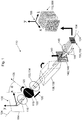
- Figure 1 schematically illustrates a particularly preferred embodiment of an imaging device 110 for acquiring spatially-resolved spectral information 112 about a target 114.
- the target 114 refers to any kind of object that can be accessed and analyzed by performing the method according to the present invention.
- light which can be used for this purpose may originate from the target 114 itself.
- an external further origin of the light may also be possible, wherein the object and/or a reflection device connected to the object may reflect the light which is, eventually, propagating from the target 114 to the device 110.
- the device 110 comprises a front optics which is designed for receiving the light which is propagating from the target 114 to the device 110.
- the front optics comprises at least one refractive optical element 116 which is designated for generating an intermediate target image of the target 114 at a focal plane 118.
- the refractive optical element 116 comprises a combination of two lenses, specifically of a wide-angle lens and a biconvex lens (not depicted here), however, other kinds of lenses or combinations thereof may also be feasible.
- the device 110 comprises a mounted optical slit 120 which is positioned at the focal plane 118 for a purpose of selecting an image line from the target image being generated at the focal plane 118.
- the mounted optical slit 120 exhibits a width of 5 ⁇ m to 100 ⁇ m, preferably of 10 ⁇ m to 25 ⁇ m, in particular of 20 ⁇ m.
- the mounted optical slit 120 is applied to a drive unit 122 which is designated for allowing a rotation of the optical slit 120 around an optical axis 124 which can here be defined by a direction 126 of a propagation of the incident light.
- an extension of the image line as generated by the mounted optical slit 120 defines an orientation 128 of the image line.
- a rotation of 0° ⁇ ⁇ ⁇ 180° of the mounted optical slit 120 would, however, be sufficient for covering all spatial positions of the target image, in particular, since the mounted optical slit 120 is arranged here in a symmetrical fashion with respect to the optical axis 124 of the device 110.
- a two-dimensional coordinate system 130 may be defined here with regard to the target 114 by directions x and y which are perpendicular to the optical axis 124 of the device 110 and perpendicular with respect to each other.
- the device 110 also comprises a collimating optical element 132 which is designated for collimating and magnifying the image line generated by the mounted optical slit 120.
- a microscope objective 134 may be used for the purpose of the collimating optical element 132.
- the device 110 comprises an image rotating prism 136 which is designated for receiving the collimated light beam provided by the collimating optical element 132 and for rotating the selected image line.
- the image rotating prism 136 may, preferably, be or comprise a Dove prism 138.
- a further kind of an image rotating prism 136 may be selected, such as a Pechan prism, or a Delta prism.
- the image rotating prism 136 acts as a derotator and is, therefore, rotated in a manner that the orientation 128 of the image line is aligned with respect to a reference orientation 140 of a diffractive optical element 142.
- the image rotating prism 136 is rotated by an angle ⁇ /2, wherein ⁇ is the angle of rotation of the mounted optical slit 120.
- the image rotating prism 136 transmits the rotated image line to the diffractive optical element 142.
- the image rotating prism 136 may be rotated in order to bring the image line back to the reference orientation 140 of a diffractive optical element 142, which may, as depicted in Figure 1 , be a vertical upright orientation, before the light is transmitted to the diffractive optical element 142.
- the device 110 comprises the diffractive optical element 142 which is designated for generating a spectrum 144 for a plurality of points on the selected image line.
- the diffractive optical element 142 may, preferably, be a transmission grating 146 which comprises a plurality of parallel lines, preferably of 100 lines/mm to 1500 lines/mm, such as 300 lines/mm.
- the parallel lines may, especially, be caused by gratings or ridges being introduced into a transparent body of the transmission grating 146.
- a direction of the parallel lines may generate the reference orientation 140 of the transmission grating 146 which is used for the alignment with the orientation 128 of the image line as described above.
- a dispersive element in particular a dispersive prism, can also be used for generating the spectrum 144.
- the device 110 may comprise a focusing lens 148 which may be used to transmit the light from the diffractive optical element 142 to an image sensor 150 as further comprised by the device 110.
- the image sensor 150 is designated for recording the spectrum 144 of the image line as generated by the diffractive optical element 142.
- the image sensor 150 may, preferably, be a CCD sensor, more preferred a monochrome CCD sensor 152.
- other kinds of image sensors, such as a CMOS sensor may also be feasible.
- the image sensor 150 may be positioned at an angle with respect to the optical axis 124 of the device 110 which may correspond to a first diffraction order of the spectrum 144 of the selected image line.
- the image sensor 150 is designated for transferring the spectrum 144 of the image line as generated by the diffractive optical element 142 to an evaluation device 154 also comprised by the device 110.
- the evaluation device 154 is designated for acquiring the spatially-resolved spectral information 112 about the target 114 by combining the spectra 144 as provided by the image sensor 150 for different angles ⁇ by which the mounted optical slit 120 is rotated.
- the evaluation device 154 is further designated for effecting a rotation of the mounted optical slit 120 and of the image rotating prism 136 for compensating the rotation of the image line.
- the spatially-resolved spectral information 112 about the target 114 is acquired by modifying the orientation 128 of the image line, preferably in a successive manner.
- the mounted optical slit 120 may, preferably, be rotated into a different position by using the drive unit 122, which may, in particular, be or comprise a stepper motor, around the optical axis 124, specifically by rotating the mounted optical slit 120 by a predefined angle, such as selected from 0.1° to 10°.
- a further spectrum 144 of the image line is recorded.
- the spatially-resolved spectral information 112 about the target 114 is acquired, as schematically depicted in Figure 1 , in form of a hyperspectral cube 156, in which each recorded spectrum 144 represents a single plane thereof.
- the hyperspectral cube 156 is a three-dimensional graphical representation 158 of the data acquired in this manner, wherein two spatial dimensions x and y cover the spatial imaging data, hereby copying the directions x and y of the target 114 with respect to the two-dimensional coordinate system 130, and a further spectral dimension having a direction ⁇ which comprises the spectroscopy data.
- Figure 2 illustrates a particularly preferred embodiment of a method 160 for acquiring the spatially-resolved spectral information 112 about the target 114.
- an image line is selected from the target image, wherein an extension of the image line defines the 128 orientation of the image line.
- a rotating step 164 the selected image line is rotated in a manner by using the image rotating prism 136 in a fashion that the orientation 128 of the image line is aligned with respect to the reference orientation 140 of the diffractive optical element142.
- the spectrum 144 is generated for a plurality of points on the selected image line by using the diffractive optical element 142.
- the spectrum 144 of the selected image line is recorded by using the image sensor 150.
- the selecting step 162 is further performed in a manner that orientation 128 of the image line is modified and a further image line is selected from the target image.
- the rotating step 164, generating step 166, and the recording step 168 are successively performed in this order.
- the desired spatially-resolved spectral information 112 about the target 114 is obtained, preferably in form of the hyperspectral cube 156 as schematically illustrated in Figure 1 .
- Figure 3 illustrates experimentally extracted spectra for plant leaf samples in a validation experiment.
- Eight disk-shaped samples 1... 8 taken from real and artificial plant leaves, respectively, are used as the target 114 by fixing to a plane and arranging in a circular array.
- pairs of leaves are fixed along a single angular line such that two leaves can be selected at the same time when the mounted optical slit 120 is rotated to the angle ⁇ .
- the target 114 is illuminated with two quartz tungsten halogen lamps having a broadband emission using, in addition, two diffuser plates for distributing the light over the samples.
- the mounted optical slit 120 and the Dove prism 138 are kept in the vertical upright position without any rotation to allow the light to transmit directly to the diffraction grating 146.
- the diffraction image carrying the spectral information for the sample is recorded by the monochrome CCD camera 152 which is used for recording the light intensity in each spectral band without any filters.
- the mounted optical slit 120 is rotated with the designated angle ⁇ for each pair of leaves
- the Dove prism 138 is rotated with half the designated angle ⁇ /2
- their diffraction images are recorded by the monochrome CCD camera 152.
- the spectral information as obtained in this fashion for each leaf 1 ... 8 is extracted using an algorithm, preferably by plotting a normalized light intensity I/I 0 as recorded in each spectral band over the spectral range of the device for a wavelength ⁇ of 400 nm ⁇ ⁇ ⁇ 750 nm.
- the acquired spectra for the eight leaves 1 ... 8 are illustrated in Figure 3 .
- the spectra of leaves 2, 3, 5, and 6 are similar to each other and, additionally, similar to the spectrum of chlorophyll, which is a well-known dye comprised by green plant leaves. This experiment provides validation for the present method and device and demonstrates a use in applications such as material sorting or target detection.
Landscapes
- Physics & Mathematics (AREA)
- Spectroscopy & Molecular Physics (AREA)
- General Physics & Mathematics (AREA)
- Investigating Or Analysing Materials By Optical Means (AREA)
- Spectrometry And Color Measurement (AREA)
Priority Applications (1)
| Application Number | Priority Date | Filing Date | Title |
|---|---|---|---|
| EP19178381.0A EP3748317A1 (de) | 2019-06-05 | 2019-06-05 | Verfahren und vorrichtung zur erfassung von räumlich aufgelösten spektralinformationen |
Applications Claiming Priority (1)
| Application Number | Priority Date | Filing Date | Title |
|---|---|---|---|
| EP19178381.0A EP3748317A1 (de) | 2019-06-05 | 2019-06-05 | Verfahren und vorrichtung zur erfassung von räumlich aufgelösten spektralinformationen |
Publications (1)
| Publication Number | Publication Date |
|---|---|
| EP3748317A1 true EP3748317A1 (de) | 2020-12-09 |
Family
ID=66770318
Family Applications (1)
| Application Number | Title | Priority Date | Filing Date |
|---|---|---|---|
| EP19178381.0A Withdrawn EP3748317A1 (de) | 2019-06-05 | 2019-06-05 | Verfahren und vorrichtung zur erfassung von räumlich aufgelösten spektralinformationen |
Country Status (1)
| Country | Link |
|---|---|
| EP (1) | EP3748317A1 (de) |
Cited By (3)
| Publication number | Priority date | Publication date | Assignee | Title |
|---|---|---|---|---|
| CN113092446A (zh) * | 2021-05-21 | 2021-07-09 | 厦门大学 | 基于道威棱镜的90度拉曼信号收集平面光路系统 |
| CN118655082A (zh) * | 2024-08-20 | 2024-09-17 | 山东大学 | 一种全玻片高光谱扫描成像装置及方法 |
| CN120451842A (zh) * | 2025-07-09 | 2025-08-08 | 浙江大学 | 高精度短波红外高光谱成像土壤塑料原位检测方法及装置 |
Citations (3)
| Publication number | Priority date | Publication date | Assignee | Title |
|---|---|---|---|---|
| US6529769B2 (en) * | 2001-03-08 | 2003-03-04 | Apti, Inc. | Apparatus for performing hyperspectral endoscopy |
| US20080285027A1 (en) | 2007-05-17 | 2008-11-20 | Emerging Technologies, Llc (A Mississippi Company) | Hyperspectral / Multispectral Dispersive System with Scanning Entry Slit Moving Across Lens Focus Plane |
| US7898656B2 (en) * | 2008-04-30 | 2011-03-01 | The General Hospital Corporation | Apparatus and method for cross axis parallel spectroscopy |
-
2019
- 2019-06-05 EP EP19178381.0A patent/EP3748317A1/de not_active Withdrawn
Patent Citations (3)
| Publication number | Priority date | Publication date | Assignee | Title |
|---|---|---|---|---|
| US6529769B2 (en) * | 2001-03-08 | 2003-03-04 | Apti, Inc. | Apparatus for performing hyperspectral endoscopy |
| US20080285027A1 (en) | 2007-05-17 | 2008-11-20 | Emerging Technologies, Llc (A Mississippi Company) | Hyperspectral / Multispectral Dispersive System with Scanning Entry Slit Moving Across Lens Focus Plane |
| US7898656B2 (en) * | 2008-04-30 | 2011-03-01 | The General Hospital Corporation | Apparatus and method for cross axis parallel spectroscopy |
Non-Patent Citations (9)
| Title |
|---|
| ABDO MOHAMMAD ET AL: "Dual-mode pushbroom hyperspectral imaging using active system components and feed-forward compensation", REVIEW OF SCIENTIFIC INSTRUMENTS, AIP, MELVILLE, NY, US, vol. 89, no. 8, 23 August 2018 (2018-08-23), XP012231048, ISSN: 0034-6748, [retrieved on 20180823], DOI: 10.1063/1.5025896 * |
| BULYGIN F V: "Tomographic Spectrometer for Spectral Analysis of Images", MEASUREMENT TECHNIQUES, KLUWER ACADEMIC PUBLISHERS-PLENUM PUBLISHERS, NE, vol. 48, no. 9, 1 September 2005 (2005-09-01), pages 907 - 912, XP019222923, ISSN: 1573-8906, DOI: 10.1007/S11018-005-0242-6 * |
| F. SIGERNESD. A. LORENTZENK. HEIAT. SVENOE: "Multipurpose spectral imager", APPL. OPTICS, vol. 39, 2000, pages 3143 - 3153 |
| G. VANER.O. GREENT.G. CHRIENH.T. ENMARKE.G. HANSENW.M. PORTER, THE AIRBORNE VISIBLE/INFRARED IMAGING SPECTROMETER (AVIRIS) IN REMOTE SENSING OF ENVIRONMENT, vol. 44, 1993, pages 127 - 143 |
| GLOBAL OPTOSIGMA: "Dove prisms", OPTICS AND OPTICAL COATINGS, 9 July 2017 (2017-07-09), XP055651512, Retrieved from the Internet <URL:https://www.global-optosigma.com/en/page_pdf/DOP.pdf?v=1499623081> [retrieved on 20191210] * |
| M. ABDOE. FORSTERP. BOHNERTV. BADILITAR. BRUNNERU. WALLRABEJ. G. KORVINK: "Dual-mode pushbroom hyperspectral imaging using active system components and feed-forward compensation", REV. SCI. INSTRUMENTS, vol. 89, 2018, pages 083113 - 11, XP012231048, DOI: doi:10.1063/1.5025896 |
| PANTAZIS Z. MOUROULISDAVID A. THOMAS: "Compact low-distortion imaging spectrometer for remote sensing", PROC. SPIE 3438, IMAGING SPECTROMETRY IV, 1998 |
| R. ARABLOUEIE. GOANS. GENSEMERB. KUSY: "Fast and robust pushbroom hyperspectral imaging via DMD-based scanning", SPIE OPT. ENG. + APPL. 9948, vol. 99480A, 2016, pages 11 |
| YANG, J. H. EVERITTM. R. DAVISC. MAO: "A CCD camera-based hyperspectral imaging system for stationary and airborne applications", GEOCARTO INT., vol. 18, 2003, pages 71 - 80, XP055482656 |
Cited By (3)
| Publication number | Priority date | Publication date | Assignee | Title |
|---|---|---|---|---|
| CN113092446A (zh) * | 2021-05-21 | 2021-07-09 | 厦门大学 | 基于道威棱镜的90度拉曼信号收集平面光路系统 |
| CN118655082A (zh) * | 2024-08-20 | 2024-09-17 | 山东大学 | 一种全玻片高光谱扫描成像装置及方法 |
| CN120451842A (zh) * | 2025-07-09 | 2025-08-08 | 浙江大学 | 高精度短波红外高光谱成像土壤塑料原位检测方法及装置 |
Similar Documents
| Publication | Publication Date | Title |
|---|---|---|
| US8154732B2 (en) | Multiband spatial heterodyne spectrometer and associated methods | |
| Bodkin et al. | Snapshot hyperspectral imaging: the hyperpixel array camera | |
| Yi et al. | Hadamard transform-based hyperspectral imaging using a single-pixel detector | |
| US7528957B2 (en) | Spectrometric process monitoring | |
| US7324196B2 (en) | Spectral encoder | |
| Abdo et al. | Spatial scanning hyperspectral imaging combining a rotating slit with a Dove prism | |
| US20080144013A1 (en) | System and method for co-registered hyperspectral imaging | |
| US9052290B2 (en) | SWIR targeted agile raman system for detection of unknown materials using dual polarization | |
| JP6475724B2 (ja) | 遠隔物体を撮像するハイパースペクトル撮像システム及び方法 | |
| US6998614B2 (en) | Hyperspectral imaging workstation having visible/near-infrared and ultraviolet image sensors | |
| EP0746746A1 (de) | Multispektrale bildanalyse | |
| Mukhtar et al. | Advances in spectral imaging: A review of techniques and technologies | |
| EP3748317A1 (de) | Verfahren und vorrichtung zur erfassung von räumlich aufgelösten spektralinformationen | |
| CN101023331A (zh) | 生物细胞和其它对象的动态化学成像 | |
| Bodkin et al. | Video-rate chemical identification and visualization with snapshot hyperspectral imaging | |
| US20020135770A1 (en) | Hybrid-imaging spectrometer | |
| JP5424108B2 (ja) | ラマンイメージング装置 | |
| US20210302305A1 (en) | Ultra-Miniature Spatial Heterodyne Spectrometer | |
| Sigernes et al. | Multipurpose spectral imager | |
| Cabib et al. | Spatially resolved Fourier transform spectroscopy (spectral imaging): a powerful tool for quantitative analytical microscopy | |
| WO2018017522A1 (en) | A method to remove the spectral components of illumination and background from multi-spectral and hyper-spectral images | |
| US20240125649A1 (en) | Ultra-Miniature Spatial Heterodyne Spectrometer | |
| JP2005532537A (ja) | 可変分散を有する光学システム | |
| US7864316B2 (en) | Spectrometric characterization of pharmaceutical heterogeneity | |
| US20080130001A1 (en) | Hybrid-imaging spectrometer |
Legal Events
| Date | Code | Title | Description |
|---|---|---|---|
| PUAI | Public reference made under article 153(3) epc to a published international application that has entered the european phase |
Free format text: ORIGINAL CODE: 0009012 |
|
| STAA | Information on the status of an ep patent application or granted ep patent |
Free format text: STATUS: THE APPLICATION HAS BEEN PUBLISHED |
|
| AK | Designated contracting states |
Kind code of ref document: A1 Designated state(s): AL AT BE BG CH CY CZ DE DK EE ES FI FR GB GR HR HU IE IS IT LI LT LU LV MC MK MT NL NO PL PT RO RS SE SI SK SM TR |
|
| AX | Request for extension of the european patent |
Extension state: BA ME |
|
| STAA | Information on the status of an ep patent application or granted ep patent |
Free format text: STATUS: THE APPLICATION IS DEEMED TO BE WITHDRAWN |
|
| 18D | Application deemed to be withdrawn |
Effective date: 20210610 |