EP3748400B1 - Système d'armes laser et procédé de mesure de distance - Google Patents
Système d'armes laser et procédé de mesure de distance Download PDFInfo
- Publication number
- EP3748400B1 EP3748400B1 EP20161072.2A EP20161072A EP3748400B1 EP 3748400 B1 EP3748400 B1 EP 3748400B1 EP 20161072 A EP20161072 A EP 20161072A EP 3748400 B1 EP3748400 B1 EP 3748400B1
- Authority
- EP
- European Patent Office
- Prior art keywords
- laser
- modulation
- intensity
- weapon system
- pulse
- Prior art date
- Legal status (The legal status is an assumption and is not a legal conclusion. Google has not performed a legal analysis and makes no representation as to the accuracy of the status listed.)
- Active
Links
Images

Classifications
-
- G—PHYSICS
- G01—MEASURING; TESTING
- G01S—RADIO DIRECTION-FINDING; RADIO NAVIGATION; DETERMINING DISTANCE OR VELOCITY BY USE OF RADIO WAVES; LOCATING OR PRESENCE-DETECTING BY USE OF THE REFLECTION OR RERADIATION OF RADIO WAVES; ANALOGOUS ARRANGEMENTS USING OTHER WAVES
- G01S17/00—Systems using the reflection or reradiation of electromagnetic waves other than radio waves, e.g. lidar systems
- G01S17/02—Systems using the reflection of electromagnetic waves other than radio waves
- G01S17/06—Systems determining position data of a target
- G01S17/08—Systems determining position data of a target for measuring distance only
- G01S17/10—Systems determining position data of a target for measuring distance only using transmission of interrupted, pulse-modulated waves
-
- F—MECHANICAL ENGINEERING; LIGHTING; HEATING; WEAPONS; BLASTING
- F41—WEAPONS
- F41H—ARMOUR; ARMOURED TURRETS; ARMOURED OR ARMED VEHICLES; MEANS OF ATTACK OR DEFENCE, e.g. CAMOUFLAGE, IN GENERAL
- F41H13/00—Means of attack or defence not otherwise provided for
- F41H13/0043—Directed energy weapons, i.e. devices that direct a beam of high energy content toward a target for incapacitating or destroying the target
- F41H13/005—Directed energy weapons, i.e. devices that direct a beam of high energy content toward a target for incapacitating or destroying the target the high-energy beam being a laser beam
-
- G—PHYSICS
- G01—MEASURING; TESTING
- G01S—RADIO DIRECTION-FINDING; RADIO NAVIGATION; DETERMINING DISTANCE OR VELOCITY BY USE OF RADIO WAVES; LOCATING OR PRESENCE-DETECTING BY USE OF THE REFLECTION OR RERADIATION OF RADIO WAVES; ANALOGOUS ARRANGEMENTS USING OTHER WAVES
- G01S17/00—Systems using the reflection or reradiation of electromagnetic waves other than radio waves, e.g. lidar systems
- G01S17/86—Combinations of lidar systems with systems other than lidar, radar or sonar, e.g. with direction finders
Definitions
- the present invention relates to a laser weapon system and methods for measuring the distance between such a laser weapon system and a target.
- Typical systems for influencing a target object using directed electromagnetic radiation use a high-energy laser beam to disrupt and/or damage the target.
- precise knowledge of the system's distance to the target object is essential, e.g., to focus the effective laser on the target object.
- Separate rangefinders are typically used to determine the distance.
- these devices use their own radiation sources to emit electromagnetic radiation.
- a widely used method for distance determination uses a separate pulsed laser beam directed at the target, see for example the publication DE 10 2010 053 896 A1
- the reflected radiation pulse can be detected by a detector, and a time-of-flight measurement can be performed based on this. By measuring the time it takes a light pulse to travel from the measuring device to the target object and back, the distance between the source and the target object is determined using the speed of light.
- Laser weapon systems are also made of US 8,218,589 B1 and EP 3 118 561 A1 known.
- the present invention is based on the object of finding simpler yet precise solutions for a laser weapon system with a rangefinder.
- this object is achieved by a laser weapon system having the features of patent claim 1 and by a method having the features of patent claim 6.
- a laser weapon system comprising an effective laser configured to irradiate a target with a continuous-wave laser beam having a predetermined beam intensity; and a radiation detector configured to detect reflected laser radiation reflected by the target with a reflected intensity.
- the effective laser is configured to impart a modulation pulse to the beam intensity of the continuous-wave laser beam
- the radiation detector is configured to detect the modulation pulse in the reflected intensity of the detected reflected laser radiation and to determine a distance of the target from the laser weapon system via a time-of-flight measurement of the modulation pulse.
- a method for measuring the distance between a laser weapon system and a target comprises irradiating the target with a continuous-wave laser beam of an effective laser of the laser weapon system at a predetermined beam intensity, wherein a modulation pulse is applied to the beam intensity of the continuous-wave laser beam; detecting reflected laser radiation with a radiation detector of the laser weapon system, which is reflected by the target with a reflected intensity; detecting the modulation pulse in the reflected intensity of the detected reflected laser radiation; and determining the distance of the target from the laser weapon system via a time-of-flight measurement of the modulation pulse.
- the effective laser operates in continuous wave mode, being modulated with one or more short, characteristic pulses. This only minimally reduces the duty cycle of the effective laser.
- the pulses can be identified in the reflected radiation using the radiation detector based on their characteristic properties. The radiation detector can, for example, continuously measure the reflected radiation. Once the pulse(s) have been identified, the distance to the target can be determined based on the time between transmission and reception of the respective pulse.
- the present invention offers a significantly simpler design than conventional laser weapon systems with a separate laser-based rangefinder.
- Typical effective lasers also offer a very long range compared to conventional rangefinders.
- range measurement can be performed at high, e.g., constant, repetition rates. Alternatively or additionally, the range measurement can also be triggered only sporadically as needed.
- the effective laser is designed to generate the modulation pulse by reducing and/or increasing the beam intensity over a pulse duration.
- the method accordingly comprises generating the modulation pulse by reducing and/or increasing the beam intensity over a pulse duration.
- modulation pulses within the meaning of the invention also include more complex short-term modulations of the beam intensity of the effective laser, e.g., an oscillation of the beam intensity with a modulation amplitude around a standard value of the beam intensity, which indicates the value at which the effective laser is operated in continuous wave mode outside the short pulse window.
- a modulation pulse within the meaning of the invention is a short-term, i.e., negligibly long change in the intensity and/or power of the effective laser, in which the intensity/power is increased by a modulation height and/or decreased by a modulation depth.
- the modulation pulse has a pulse duration of less than 1 ms.
- the pulse duration can be 0.5 ms.
- the effective laser is designed to generate the modulation pulse by briefly operating the effective laser in an overload range and/or an underload range.
- the method accordingly comprises generating the modulation pulse in an overload range and/or an underload range.
- the laser diodes commonly used in effective lasers can typically be driven briefly ( ⁇ 1 ms) into an overload range.
- the power or intensity can be temporarily increased by up to 50% above the standard value.
- the intensity of the effective laser can also be modulated in such a way that the effective laser is driven not only into the overload range but also into an underload range.
- the modulation pulse can exhibit a complex intensity profile, which can, for example, include an oscillation or multiple changes between the overload range and the underload range.
- the effective laser can be configured to impose a plurality of modulation pulses on the beam intensity.
- the effective laser can further be configured to adaptively adjust a modulation amplitude of the modulation pulses.
- the method can accordingly comprise imposing a plurality of modulation pulses on the beam intensity.
- the method can further comprise adaptively adjusting a modulation amplitude of the modulation pulses.
- a modulation depth and/or modulation height i.e., a deviation from a standard intensity of the effective laser, is therefore not necessarily fixed, but can be adaptively adjusted.
- the modulation depth or modulation height can be reduced if the modulation pulse is well detected in the receiver.
- Modulation amplitude is defined as the amount of change in the intensity or power of the effective laser around the standard value.
- the radiation detector can be designed to detect the modulation pulse by comparing a signal curve of the reflection intensity of the detected reflection laser radiation with a signal curve of the beam intensity of the continuous-wave laser beam.
- the method may include detecting the modulation pulse by comparing a signal profile of the reflection intensity of the detected reflection laser radiation with a signal profile of the beam intensity of the continuous-wave laser beam.
- the characteristic modulation of the received signal is usually not compared with a target signal (signal at a modulation input), but with an actual value (measured optical power of the active laser), i.e., with the output signal of the corresponding laser diodes. Inaccuracies such as fluctuations ("jitter”) or the like are thus automatically taken into account.
- the detection of a falling/rising edge in the optical power curve can be used.
- the difference between the times of the falling/rising edges determines the time period for determining the distance.
- the modulation pulse can have a characteristic amplitude variation in a modulation amplitude.
- the radiation detector can be configured to perform the transit time measurement by means of a correlation measurement in the signal waveforms of the intensities.
- the method may accordingly include carrying out the runtime measurement by means of a correlation measurement in the signal curves of the intensities.
- the duration can be determined, for example, by measuring the correlation of the signal waveforms of the transmitted and received optical power.
- Autocorrelation for example, enables subsampling and thus an even better distance estimation compared to the modulation time.
- slow current regulators of the laser diodes of the high-energy laser
- such techniques enable significantly improved edge and signal resolution and thus improved distance estimation.
- Figure 1 shows a schematic view of a laser weapon system 1 according to an embodiment of the invention.
- Fig. 8 shows a schematic flow diagram of a method for distance measurement with the laser weapon system from Fig. 1 .
- rangefinders are usually constructed from a transmitter (light source/laser with optics), a receiver (optics and receiving diode(s)), and additional electronics for evaluation and control.
- a transmitter light source/laser with optics
- a receiver opticals and receiving diode(s)
- additional electronics for evaluation and control.
- a single or multiple separate light pulses are emitted from a transmitter toward the target object, and the time it takes for the pulse(s) to travel from the transmitter to the target object and back to the receiver is measured. This ultimately allows the distance to be determined.
- a (high-energy) laser beam (“effective laser”) is directed at a target object.
- precise knowledge of the distance to the target object is helpful or necessary, e.g., to focus the effective laser on the target object and/or to focus the image for observation or tracking.
- Separate rangefinders are typically used to determine the distance. Depending on their operating principle, these devices then use their own sources to emit a light pulse.
- the laser weapon system 1 shown uses a completely different approach, requiring no dedicated source. Instead, a continuous-wave laser 2 is used as a rangefinder. The only additional component required is a suitable receiver for detection (radiation detector 3).
- the laser weapon system 1 in Fig. 1 thus an effective laser 2, which is designed to irradiate a target 4 with a continuous-wave laser beam 5 having a predetermined beam intensity 6. Furthermore, the laser weapon system 1 comprises a radiation detector 3, which is designed to detect reflected laser radiation 7 reflected by the target 4 with a reflection intensity 8.
- the effective laser 2 is designed to impress a modulation pulse 9 on the beam intensity 6 of the continuous wave laser beam 5.
- the effective laser 2 increases or decreases the beam intensity 6 over a short pulse duration 10, according to the invention less than 1 ms.
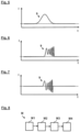
- a short-term reduction in the intensity or power of the effective laser 2 can lead to the Fig. 2 and 3 shown intensity curves.
- Fig. 5 take the form shown, where the dashed line represents a standard value as set during continuous wave operation.
- Fig. 6 a modulation pulse 9 with a complex time course, in which one or more laser diodes of the effective laser 2 are moved into an overload range.
- Fig. 7 represents another example in which the active laser 2 is driven not only into the overload range, but also into an underload range.
- the intensity or power fluctuates or oscillates around the standard value (dashed line).
- the modulation pulse 9 thus acquires a characteristic shape. This characteristic shape characterizes the modulation pulse 9 and can be recognized in the reflected radiation to simplify the detection of the pulse.
- the radiation detector 3 is further configured to detect the modulation pulse 9 in the reflection intensity 8 of the detected reflection laser radiation 7 and to determine a distance of the target 4 from the laser weapon system 1 via a transit time measurement of the modulation pulse 9. For this purpose, a signal curve of the reflection intensity 8 of the detected reflection laser radiation 7 can be compared with a signal curve of the beam intensity 6 of the continuous wave laser beam 5.
- the radiation detector 3 can be designed to carry out the transit time measurement by means of an edge detection in the signal curves of the intensities 6, 8, e.g. in the case of a simple modulation, as in Fig. 2, 3 and 5
- the radiation detector 3 can be designed to carry out the transit time measurement by means of a correlation measurement in the signal curves of the intensities 6, 8, e.g. in the case of a complex modulation, as shown in Figs. 6 and 7 can be seen.
- the effective laser 2 can further be configured to impart a plurality of (regular or merely sporadic) modulation pulses 9 to the beam intensity 6.
- the depth and/or height of the individual modulation pulses 9 above a standard value of the intensity/power can be adaptively adjusted, e.g., depending on a detection quality.
- Fig. 4 shows an example in which a pulse depth is gradually reduced.
- the described principle for distance measurement thus inverts, in a sense, a conventional laser rangefinder: Instead of emitting and detecting individual pulses, a continuous laser beam is subjected to characteristic modulation pulses, which are then used to measure the time of flight. This offers the significant advantage that the effective laser itself can simultaneously function as a rangefinder, simplifying the entire design of the laser weapon system.
Landscapes
- Engineering & Computer Science (AREA)
- Physics & Mathematics (AREA)
- Radar, Positioning & Navigation (AREA)
- Remote Sensing (AREA)
- Electromagnetism (AREA)
- Computer Networks & Wireless Communication (AREA)
- General Physics & Mathematics (AREA)
- Optics & Photonics (AREA)
- General Engineering & Computer Science (AREA)
- Optical Radar Systems And Details Thereof (AREA)
Claims (10)
- Système d'arme laser (1), comportant :un laser actif (2), qui est conçu pour irradier une cible (4) avec un faisceau laser continu (5) avec une intensité de faisceau (6) prédéfinie ; etun détecteur de rayonnement (3), qui est conçu pour détecter un rayonnement laser réfléchi (7) qui est réfléchi par la cible (4) avec une intensité de réflexion (8) ;dans lequel le laser actif (2) est conçu pour appliquer une impulsion de modulation (9) à l'intensité de faisceau (6) du faisceau laser continu (5) en mode continu, etdans lequel le détecteur de rayonnement (3) est conçu pour déceler l'impulsion de modulation (9) dans l'intensité de réflexion (8) du rayonnement laser réfléchi (7) détecté et pour déterminer, par le biais d'une mesure du temps de propagation de l'impulsion de modulation (9), une distance entre la cible (4) et le système d'arme laser (1) ;dans lequel le laser actif (2) est conçu pour générer l'impulsion de modulation (6) par une baisse et/ou une hausse de l'intensité de faisceau (6) sur une durée d'impulsion (10) inférieure à 1 ms en faisant fonctionner le laser actif (2) dans une plage de surcharge et/ou une plage de sous-charge, dans laquelle l'intensité de faisceau (6) présente un écart égal à une amplitude de modulation (11) par rapport à une intensité standard du laser actif (2).
- Système d'arme laser (1) selon la revendication 1, dans lequel le laser actif (2) est conçu pour appliquer plusieurs impulsions de modulation (9) à l'intensité de faisceau (6) et dans lequel le laser actif (2) est conçu pour ajuster de manière adaptative une amplitude de modulation (11) des impulsions de modulation (9).
- Système d'arme laser (1) selon la revendication 1 ou 2, dans lequel le détecteur de rayonnement (3) est conçu pour déceler l'impulsion de modulation (9) par comparaison d'une courbe de signal de l'intensité de réflexion (8) du rayonnement laser réfléchi (7) détecté avec une courbe de signal de l'intensité de faisceau (6) du faisceau laser continu (5).
- Système d'arme laser (1) selon l'une des revendications 1 à 3, dans lequel le détecteur de rayonnement (3) est conçu pour effectuer la mesure du temps de propagation au moyen d'une détection de flancs dans les courbes de signal des intensités (6, 8).
- Système d'arme laser (1) selon l'une des revendications 1 à 4, dans lequel l'impulsion de modulation (9) présente une variation d'amplitude caractéristique dans une amplitude de modulation (11) et dans lequel le détecteur de rayonnement (3) est conçu pour effectuer la mesure du temps de propagation par une mesure de corrélation dans les courbes de signal des intensités (6, 8).
- Procédé (M) de mesure de distance entre un système d'arme laser (1) et une cible (4), comportant :l'irradiation (M1) de la cible (4) avec un faisceau laser continu (5) d'un laser actif (2) du système d'arme laser (1) avec une intensité de faisceau (6) prédéfinie, une impulsion de modulation (9) étant appliquée à l'intensité de faisceau (6) du faisceau laser continu (5) ;la détection (M2), au moyen d'un détecteur de rayonnement (3) du système d'arme laser (1), d'un rayonnement laser réfléchi (7) qui est réfléchi par la cible (4) avec une intensité de réflexion (8) ;le décèlement (M3) de l'impulsion de modulation (9) dans l'intensité de réflexion (8) du rayonnement laser réfléchi (7) détecté ; etla détermination (M4) de la distance entre la cible (4) et le système d'arme laser (1) par le biais d'une mesure de la durée de propagation de l'impulsion de modulation (9) ;dans lequel l'impulsion de modulation (9) est générée par une baisse et/ou une hausse de l'intensité de faisceau (6) sur une durée d'impulsion (10) inférieure à 1 ms en faisant fonctionner le laser actif (2) dans une plage de surcharge et/ou une plage de sous-charge, dans laquelle l'intensité de faisceau (6) présente un écart égal à une amplitude de modulation (11) par rapport à une intensité standard du laser actif (2).
- Procédé (M) selon la revendication 6, dans lequel plusieurs impulsions de modulation (9) sont appliquées à l'intensité de faisceau (6) et dans lequel une amplitude de modulation (11) des impulsions de modulation (9) est ajustée de manière adaptative.
- Procédé (M) selon la revendication 6 ou 7, dans lequel l'impulsion de modulation (9) est décelée par comparaison d'une courbe de signal de l'intensité de réflexion (8) du rayonnement laser réfléchi (7) détecté avec une courbe de signal de l'intensité de faisceau (6) du faisceau laser continu (5).
- Procédé (M) selon l'une des revendications 6 à 8, dans lequel la mesure du temps de propagation est effectuée au moyen d'une détection de flancs dans les courbes de signal des intensités (6, 8).
- Procédé (M) selon l'une des revendications 6 à 9, dans lequel l'impulsion de modulation (9) présente une variation d'amplitude caractéristique dans une amplitude de modulation (11) et dans lequel la mesure du temps de propagation est effectuée par une mesure de corrélation dans les courbes de signal des intensités (6, 8).
Applications Claiming Priority (1)
| Application Number | Priority Date | Filing Date | Title |
|---|---|---|---|
| DE102019003948.3A DE102019003948A1 (de) | 2019-06-06 | 2019-06-06 | Laserwaffensystem und Verfahren zur Entfernungsmessung |
Publications (3)
| Publication Number | Publication Date |
|---|---|
| EP3748400A1 EP3748400A1 (fr) | 2020-12-09 |
| EP3748400B1 true EP3748400B1 (fr) | 2025-06-04 |
| EP3748400C0 EP3748400C0 (fr) | 2025-06-04 |
Family
ID=69770707
Family Applications (1)
| Application Number | Title | Priority Date | Filing Date |
|---|---|---|---|
| EP20161072.2A Active EP3748400B1 (fr) | 2019-06-06 | 2020-03-05 | Système d'armes laser et procédé de mesure de distance |
Country Status (3)
| Country | Link |
|---|---|
| EP (1) | EP3748400B1 (fr) |
| DE (1) | DE102019003948A1 (fr) |
| ES (1) | ES3036844T3 (fr) |
Family Cites Families (6)
| Publication number | Priority date | Publication date | Assignee | Title |
|---|---|---|---|---|
| US5936229A (en) * | 1996-04-02 | 1999-08-10 | Trw Inc. | Tracking means for distant ballistic missile targets comprising means for tracking largest radius of curvature |
| US7746450B2 (en) * | 2007-08-28 | 2010-06-29 | Science Applications International Corporation | Full-field light detection and ranging imaging system |
| US8218589B1 (en) * | 2008-07-28 | 2012-07-10 | The United States Of America As Represented By The Secretary Of The Air Force | High-energy laser atmospheric compensation and aimpoint maintenance |
| DE102010053896A1 (de) | 2010-12-09 | 2012-06-14 | Lfk-Lenkflugkörpersysteme Gmbh | Zielbekämpfungssystem |
| DE102012104349A1 (de) * | 2012-05-21 | 2013-11-21 | Deutsches Zentrum für Luft- und Raumfahrt e.V. | Verfahren zur Bestimmung der Flugbahn eines Objekts und Flugbahnbestimmungsvorrichtung |
| DE102015009200A1 (de) * | 2015-07-15 | 2017-01-19 | Diehl Bgt Defence Gmbh & Co. Kg | Energiewirksystem und Waffensystem |
-
2019
- 2019-06-06 DE DE102019003948.3A patent/DE102019003948A1/de active Pending
-
2020
- 2020-03-05 ES ES20161072T patent/ES3036844T3/es active Active
- 2020-03-05 EP EP20161072.2A patent/EP3748400B1/fr active Active
Also Published As
| Publication number | Publication date |
|---|---|
| DE102019003948A1 (de) | 2020-12-10 |
| ES3036844T3 (en) | 2025-09-24 |
| EP3748400A1 (fr) | 2020-12-09 |
| EP3748400C0 (fr) | 2025-06-04 |
Similar Documents
| Publication | Publication Date | Title |
|---|---|---|
| DE2216765C3 (de) | Verfahren und Einrichtung zur Entfernungsmessung | |
| EP1936400B1 (fr) | Lecteur laser | |
| EP3070494B1 (fr) | Procédé de télémétrie électro-optique et télémètre associé | |
| DE69716334T2 (de) | Modal-Verarbeitung zur Abstandsmessung mittels Multipulse-Multireturn-Signalen zur Clutter-Beseitigung | |
| EP1423731B1 (fr) | Procede et dispositif pour acquerir une image telemetrique tridimensionnelle | |
| EP0165403B1 (fr) | Procédé pour commander la dynamique d'un appareil de mesure de distance selon le principe de la mesure du temps de propagation d'une impulsion de lumière et dispositif pour la mise en oeuvre de ce procédé | |
| EP2238470A1 (fr) | Procédé et dispositif pour déterminer une distance par rapport à un objet | |
| EP2597482A1 (fr) | Dispositif et capteur de mesure d'éloignement à l'aide de la durée de fonctionnement d'impulsions compensées | |
| DE102012208308A1 (de) | Optisches Entfernungsmessgerät mit Kalibriereinrichtung zum Berücksichtigen von Übersprechen | |
| DE102007030978A1 (de) | Radarvorrichtung | |
| EP3538925B1 (fr) | Système lidar | |
| EP2088453A1 (fr) | Capteur optoélectronique destiné à la mesure d'éloignement | |
| EP4083660A1 (fr) | Dispositif lidar doppler destiné à la détection des situations de vent et/ou de turbulences | |
| EP0093437A2 (fr) | Dispositif de réglage électronique pour télémètre électro-optique utilisant un procédé de mesure de la durée de parcours d'une impulsion lumineuse | |
| EP0571566A1 (fr) | Dispositif pour la mesure de distances par ultrasons. | |
| EP2182379B1 (fr) | Scanner laser mesurant l'éloignement | |
| DE2257445B2 (de) | Visuell ausrichtbarer elektrooptischer laufzeit-entfernungsmesser mit intensitaetssteuerung | |
| DE10153742A1 (de) | Verfahren und Vorrichtung zur Aufnahme eines dreidimensionalen Abstandsbildes | |
| WO2003062851A1 (fr) | Procede et dispositif de telemetrie optique | |
| DE102008032532B4 (de) | Verfahren und Vorrichtung zum präparierenden Lasermaterialabtrag | |
| DE3219452C2 (de) | Dynamik-Steuerungsanordnung für ein Entfernungsmeßgerät | |
| EP3748400B1 (fr) | Système d'armes laser et procédé de mesure de distance | |
| EP2565669B1 (fr) | Procédé destiné à supprimer un échosignal | |
| DE2744092A1 (de) | Ultraschall-entfernungsmessystem | |
| DE10018948B4 (de) | Optoelektronische Vorrichtung |
Legal Events
| Date | Code | Title | Description |
|---|---|---|---|
| PUAI | Public reference made under article 153(3) epc to a published international application that has entered the european phase |
Free format text: ORIGINAL CODE: 0009012 |
|
| STAA | Information on the status of an ep patent application or granted ep patent |
Free format text: STATUS: THE APPLICATION HAS BEEN PUBLISHED |
|
| AK | Designated contracting states |
Kind code of ref document: A1 Designated state(s): AL AT BE BG CH CY CZ DE DK EE ES FI FR GB GR HR HU IE IS IT LI LT LU LV MC MK MT NL NO PL PT RO RS SE SI SK SM TR |
|
| AX | Request for extension of the european patent |
Extension state: BA ME |
|
| STAA | Information on the status of an ep patent application or granted ep patent |
Free format text: STATUS: REQUEST FOR EXAMINATION WAS MADE |
|
| 17P | Request for examination filed |
Effective date: 20210128 |
|
| RBV | Designated contracting states (corrected) |
Designated state(s): AL AT BE BG CH CY CZ DE DK EE ES FI FR GB GR HR HU IE IS IT LI LT LU LV MC MK MT NL NO PL PT RO RS SE SI SK SM TR |
|
| STAA | Information on the status of an ep patent application or granted ep patent |
Free format text: STATUS: EXAMINATION IS IN PROGRESS |
|
| 17Q | First examination report despatched |
Effective date: 20220511 |
|
| GRAP | Despatch of communication of intention to grant a patent |
Free format text: ORIGINAL CODE: EPIDOSNIGR1 |
|
| STAA | Information on the status of an ep patent application or granted ep patent |
Free format text: STATUS: GRANT OF PATENT IS INTENDED |
|
| INTG | Intention to grant announced |
Effective date: 20250207 |
|
| GRAS | Grant fee paid |
Free format text: ORIGINAL CODE: EPIDOSNIGR3 |
|
| GRAA | (expected) grant |
Free format text: ORIGINAL CODE: 0009210 |
|
| STAA | Information on the status of an ep patent application or granted ep patent |
Free format text: STATUS: THE PATENT HAS BEEN GRANTED |
|
| AK | Designated contracting states |
Kind code of ref document: B1 Designated state(s): AL AT BE BG CH CY CZ DE DK EE ES FI FR GB GR HR HU IE IS IT LI LT LU LV MC MK MT NL NO PL PT RO RS SE SI SK SM TR |
|
| REG | Reference to a national code |
Ref country code: GB Ref legal event code: FG4D Free format text: NOT ENGLISH |
|
| REG | Reference to a national code |
Ref country code: CH Ref legal event code: EP |
|
| REG | Reference to a national code |
Ref country code: DE Ref legal event code: R096 Ref document number: 502020011142 Country of ref document: DE |
|
| REG | Reference to a national code |
Ref country code: IE Ref legal event code: FG4D Free format text: LANGUAGE OF EP DOCUMENT: GERMAN |
|
| U01 | Request for unitary effect filed |
Effective date: 20250617 |
|
| U07 | Unitary effect registered |
Designated state(s): AT BE BG DE DK EE FI FR IT LT LU LV MT NL PT RO SE SI Effective date: 20250701 |
|
| REG | Reference to a national code |
Ref country code: ES Ref legal event code: FG2A Ref document number: 3036844 Country of ref document: ES Kind code of ref document: T3 Effective date: 20250924 |
|
| PG25 | Lapsed in a contracting state [announced via postgrant information from national office to epo] |
Ref country code: NO Free format text: LAPSE BECAUSE OF FAILURE TO SUBMIT A TRANSLATION OF THE DESCRIPTION OR TO PAY THE FEE WITHIN THE PRESCRIBED TIME-LIMIT Effective date: 20250904 Ref country code: GR Free format text: LAPSE BECAUSE OF FAILURE TO SUBMIT A TRANSLATION OF THE DESCRIPTION OR TO PAY THE FEE WITHIN THE PRESCRIBED TIME-LIMIT Effective date: 20250905 |
|
| PG25 | Lapsed in a contracting state [announced via postgrant information from national office to epo] |
Ref country code: PL Free format text: LAPSE BECAUSE OF FAILURE TO SUBMIT A TRANSLATION OF THE DESCRIPTION OR TO PAY THE FEE WITHIN THE PRESCRIBED TIME-LIMIT Effective date: 20250604 |
|
| PG25 | Lapsed in a contracting state [announced via postgrant information from national office to epo] |
Ref country code: HR Free format text: LAPSE BECAUSE OF FAILURE TO SUBMIT A TRANSLATION OF THE DESCRIPTION OR TO PAY THE FEE WITHIN THE PRESCRIBED TIME-LIMIT Effective date: 20250604 |
|
| PG25 | Lapsed in a contracting state [announced via postgrant information from national office to epo] |
Ref country code: RS Free format text: LAPSE BECAUSE OF FAILURE TO SUBMIT A TRANSLATION OF THE DESCRIPTION OR TO PAY THE FEE WITHIN THE PRESCRIBED TIME-LIMIT Effective date: 20250904 |
|
| PG25 | Lapsed in a contracting state [announced via postgrant information from national office to epo] |
Ref country code: IS Free format text: LAPSE BECAUSE OF FAILURE TO SUBMIT A TRANSLATION OF THE DESCRIPTION OR TO PAY THE FEE WITHIN THE PRESCRIBED TIME-LIMIT Effective date: 20251004 |
|
| PG25 | Lapsed in a contracting state [announced via postgrant information from national office to epo] |
Ref country code: SM Free format text: LAPSE BECAUSE OF FAILURE TO SUBMIT A TRANSLATION OF THE DESCRIPTION OR TO PAY THE FEE WITHIN THE PRESCRIBED TIME-LIMIT Effective date: 20250604 |
|
| PG25 | Lapsed in a contracting state [announced via postgrant information from national office to epo] |
Ref country code: CZ Free format text: LAPSE BECAUSE OF FAILURE TO SUBMIT A TRANSLATION OF THE DESCRIPTION OR TO PAY THE FEE WITHIN THE PRESCRIBED TIME-LIMIT Effective date: 20250604 |
|
| PG25 | Lapsed in a contracting state [announced via postgrant information from national office to epo] |
Ref country code: SK Free format text: LAPSE BECAUSE OF FAILURE TO SUBMIT A TRANSLATION OF THE DESCRIPTION OR TO PAY THE FEE WITHIN THE PRESCRIBED TIME-LIMIT Effective date: 20250604 |
|
| PGFP | Annual fee paid to national office [announced via postgrant information from national office to epo] |
Ref country code: GB Payment date: 20260324 Year of fee payment: 7 |
|
| PLBE | No opposition filed within time limit |
Free format text: ORIGINAL CODE: 0009261 |
|
| STAA | Information on the status of an ep patent application or granted ep patent |
Free format text: STATUS: NO OPPOSITION FILED WITHIN TIME LIMIT |
|
| REG | Reference to a national code |
Ref country code: CH Ref legal event code: L10 Free format text: ST27 STATUS EVENT CODE: U-0-0-L10-L00 (AS PROVIDED BY THE NATIONAL OFFICE) Effective date: 20260416 |