EP3748660A1 - Procédé de détermination d'état d'une unité d'entraînement pour un appareil de commutation haute ou moyenne tension et appareil de commutation haute ou moyenne tension - Google Patents
Procédé de détermination d'état d'une unité d'entraînement pour un appareil de commutation haute ou moyenne tension et appareil de commutation haute ou moyenne tension Download PDFInfo
- Publication number
- EP3748660A1 EP3748660A1 EP19178407.3A EP19178407A EP3748660A1 EP 3748660 A1 EP3748660 A1 EP 3748660A1 EP 19178407 A EP19178407 A EP 19178407A EP 3748660 A1 EP3748660 A1 EP 3748660A1
- Authority
- EP
- European Patent Office
- Prior art keywords
- vibration pattern
- drive unit
- switching device
- medium voltage
- voltage switching
- Prior art date
- Legal status (The legal status is an assumption and is not a legal conclusion. Google has not performed a legal analysis and makes no representation as to the accuracy of the status listed.)
- Withdrawn
Links
- 238000000034 method Methods 0.000 title claims abstract description 34
- 230000008569 process Effects 0.000 claims abstract description 20
- 230000001133 acceleration Effects 0.000 claims abstract description 19
- 238000012545 processing Methods 0.000 claims description 16
- 230000005540 biological transmission Effects 0.000 claims description 8
- 238000005259 measurement Methods 0.000 claims description 6
- 238000012423 maintenance Methods 0.000 description 6
- 230000032683 aging Effects 0.000 description 2
- 238000004458 analytical method Methods 0.000 description 2
- 238000011156 evaluation Methods 0.000 description 2
- 230000009466 transformation Effects 0.000 description 2
- 230000008859 change Effects 0.000 description 1
- 238000010276 construction Methods 0.000 description 1
- 238000011161 development Methods 0.000 description 1
- 230000018109 developmental process Effects 0.000 description 1
- 238000003745 diagnosis Methods 0.000 description 1
- 238000010586 diagram Methods 0.000 description 1
- 238000000691 measurement method Methods 0.000 description 1
- 230000007246 mechanism Effects 0.000 description 1
- 230000010355 oscillation Effects 0.000 description 1
- 230000000717 retained effect Effects 0.000 description 1
- 238000012552 review Methods 0.000 description 1
- 230000035882 stress Effects 0.000 description 1
- 238000012360 testing method Methods 0.000 description 1
Images



Classifications
-
- H—ELECTRICITY
- H01—ELECTRIC ELEMENTS
- H01H—ELECTRIC SWITCHES; RELAYS; SELECTORS; EMERGENCY PROTECTIVE DEVICES
- H01H11/00—Apparatus or processes specially adapted for the manufacture of electric switches
- H01H11/0062—Testing or measuring non-electrical properties of switches, e.g. contact velocity
-
- H—ELECTRICITY
- H01—ELECTRIC ELEMENTS
- H01H—ELECTRIC SWITCHES; RELAYS; SELECTORS; EMERGENCY PROTECTIVE DEVICES
- H01H33/00—High-tension or heavy-current switches with arc-extinguishing or arc-preventing means
- H01H33/02—Details
- H01H33/28—Power arrangements internal to the switch for operating the driving mechanism
-
- H—ELECTRICITY
- H01—ELECTRIC ELEMENTS
- H01H—ELECTRIC SWITCHES; RELAYS; SELECTORS; EMERGENCY PROTECTIVE DEVICES
- H01H33/00—High-tension or heavy-current switches with arc-extinguishing or arc-preventing means
- H01H33/02—Details
- H01H33/42—Driving mechanisms
-
- H—ELECTRICITY
- H01—ELECTRIC ELEMENTS
- H01H—ELECTRIC SWITCHES; RELAYS; SELECTORS; EMERGENCY PROTECTIVE DEVICES
- H01H71/00—Details of the protective switches or relays covered by groups H01H73/00 - H01H83/00
- H01H71/04—Means for indicating condition of the switching device
- H01H2071/044—Monitoring, detection or measuring systems to establish the end of life of the switching device, can also contain other on-line monitoring systems, e.g. for detecting mechanical failures
-
- H—ELECTRICITY
- H01—ELECTRIC ELEMENTS
- H01H—ELECTRIC SWITCHES; RELAYS; SELECTORS; EMERGENCY PROTECTIVE DEVICES
- H01H2300/00—Orthogonal indexing scheme relating to electric switches, relays, selectors or emergency protective devices covered by H01H
- H01H2300/052—Controlling, signalling or testing correct functioning of a switch
Definitions
- the condition of the equipment that is used in the network plays a decisive role in the secure operation of high or medium voltage networks. Therefore, the equipment must be checked and renewed at different intervals but at regular intervals. Economic renewal and maintenance planning requires knowledge of the condition of the equipment, which is why a technical review of the condition of the equipment makes a significant contribution to the economic efficiency of network operation in general.
- kinematic chain which consists of springs, latches, release and tensioning mechanisms, is a complex system whose functionality can only be checked with great effort. This is currently done by mechanical disassembly, mechanical testing and subsequent reassembly. A high susceptibility to errors was found particularly when reassembling switchgear and their drive systems. The service life after maintenance has been carried out is often shorter than before maintenance.
- the object of the invention is to provide a method for determining the status of a drive unit for a high or medium voltage switching device and a high or medium voltage switching device per se, which is suitable for generating a technical status determination and thereby eliminating the need for mechanical or manual intervention to avoid or reduce the switching device as far as possible.
- the object is achieved in a method for determining the state of a drive unit for high or medium voltage switching devices with the features of claim 1 and in a high or medium voltage switching device with the features of claim 8.
- the method according to the invention for determining the state of a drive unit for high or medium voltage switching devices comprises the following steps: First, a switching process is carried out with the high or medium voltage switching device. A characteristic vibration pattern for the load-free switching process is recorded, with at least one acceleration sensor being used. This characteristic vibration pattern is then made available in a database.
- this characteristic vibration pattern makes it possible to keep this vibration pattern, which is recorded with an intact, new or fault-free device, available for later comparison measurements.
- This characteristic vibration pattern can serve as a template for further comparison measurements that are carried out on the same device or on devices of the same construction.
- the storage of this vibration pattern in a database is suitable so that the operator or the person responsible for maintenance for the high or medium voltage switching device has access to this basic information that is characteristic of the corresponding switching device at any time.
- a reference vibration pattern can likewise be created in a reference measurement in a reference switching process. This can in turn take place with the same switching device or with a structurally identical switching device. A comparison is then made between the reference vibration pattern and the characteristic vibration pattern and a state variable of the drive unit is determined.
- the term state variable is understood to mean any information that can be obtained from the comparison of the two vibration patterns using different methods. For this purpose, for example, a frequency analysis in the form of an FFT (Fast Fourier Transformation) can be carried out.
- FFT Fast Fourier Transformation
- the determination mode of the state variable is variable, it can already be specified when the switching device is put into operation, but it can also change at any time during operation due to new findings and new methods. This is possible because the characteristic vibration pattern is recorded at the time of commissioning or shortly thereafter in the case of a fault-free device, which is retained over the entire operating time of the switching device and can be used at any time during the operating time, which can be up to 40 years.
- the sensor data of the acceleration sensor are recorded by a data processing device arranged on the drive unit and converted into the reference vibration pattern.
- This direct processing of the sensor data on the device enables the direct evaluation of the reference vibration pattern on the one hand and on the other hand the transmission of this vibration pattern via a data network to a computer system and the storage in the database there.
- the vibration is measured on a drive shaft by means of the acceleration sensor.
- the drive shaft is one of the most stressed components in the drive unit and it provides a characteristic vibration pattern that is particularly easy to evaluate.
- this is preferably determined in a load-free switching process.
- This is an off-line measurement method, as the switching device is separated from the mains.
- an online measurement can also be useful, with the vibration pattern (the characteristic and / or the reference pattern) being recorded during a switching process that is taking place anyway.
- a diagnosis of the drive system can be carried out during an unplanned switching process outside of fixed maintenance intervals and, if necessary, a forecast can be made about the further service life.
- observations of pattern development during the switching processes could also briefly indicate errors.
- This high or medium voltage switching device has a drive unit for a switching contact, at least one acceleration sensor being arranged in the area of the drive unit. Furthermore, a control device is provided for the drive unit which is designed to carry out a preferably load-free shifting process and to record a characteristic vibration pattern for the load-free shifting process with the acceleration sensor and to provide the characteristic vibration pattern in a database.
- the high or medium voltage switching device according to the invention according to claim 7 has the same advantages that have already been explained with regard to claim 1.
- the term drive unit is understood to mean all mechanical components that are used to drive switching contacts of the high or medium voltage switching device. This includes in particular the drive itself, which kinematically induces the mechanical movement, the drive rods and the housing.
- the term control device means a device understood, which on the one hand is suitable to control a load-free switching process, this control device not necessarily having to be arranged directly on the switching device. Although this is generally useful, the control device can, however, also be part of a central control device that is connected to the switching device via the data network.
- the control device can include further sub-devices, for example a data processing device, which evaluates the sensor data and combines them to form the characteristic vibration pattern.
- It can also contain a data transmission device which is suitable for transmitting either the characteristic vibration pattern or the reference vibration pattern or the raw sensor data via the data network to a database or a central station, for example a control room.
- a database is understood to mean an electronic storage medium in which information about the characteristic vibration pattern is stored; in this case the database can be arranged either directly on the switching device itself or directly on the type of control device, but it can also be on any Location within the data network and thus connected to the medium-voltage switching device.
- FIG 1 is a schematic representation of a conventional high-voltage switching device, which can also be designed in a similar form as a medium-voltage switching device.
- the high-voltage switching device 4 comprises three upright switches 3 which each contain switching contacts 20 and are mechanically connected via a single central drive unit 2.
- the drive unit 2 comprises in particular a drive shaft 16, which is shown schematically in the left of the three switches 3.
- the drive unit 2 also includes a drive 30, which can be designed, for example, in the form of a spring drive or an electric motor.
- the drive unit 2 is surrounded by a housing 18.
- acceleration sensors 8 are arranged on various components of the drive unit 2.
- At least one acceleration sensor 8 is expedient, but several acceleration sensors 8 can be attached to various components of the drive unit 2 in order to increase the informative value of the vibration measurement.
- the drive rod 16 is particularly suitable for receiving an acceleration sensor 8, from which concrete and meaningful vibration patterns can be determined.
- the other hand is the case 18 a place at which a vibration pattern can be recorded in that information about all components of the drive unit 2 flows together.
- the acceleration sensors 8 are suitable for recording a vibration pattern of the drive unit 2.
- a characteristic vibration pattern of a brand-new drive unit 2 or of the high or medium voltage switching device connected to it Brand new is understood to mean that the characteristic vibration pattern 6 is recorded either during final assembly of the switching device 4 or after the switching device has been installed in the field at the network operator's before or shortly after commissioning.
- a control device 22 is provided, which is shown in FIG Figure 1 is shown schematically by box 22. This box 22 is shown some distance from the drive unit 2, which will be described in more detail later. This means that the control device can either be arranged directly on the drive unit 2 or on the switching device 4, but can also be arranged at a distance from this switching device, for example in a control room.
- the control device 22 in the present embodiment comprises a data processing device 12 and a data transmission device 24.
- the data processing device 12 is designed to send raw data on the vibration or oscillation of the individual components of the drive unit 2 via a connecting line 28 to the control device 22 or to the in this case to transmit data processing device 12 contained in it.
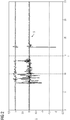
- the data processing device 12 processes this data into the in Figure 2 Characteristic vibration pattern 6 shown as an example.
- the control device 22 or the data transmission device 24, which can be part of the control device 22, then transmits the determined data via a data network 14 to a database (not shown here) 10 or to an in Figure 1 Central station 26, also not shown (see Fig. 3 or. Fig. 4 ).
- FIG. 2 shows, as already explained, a characteristic vibration pattern of a drive unit 2, for example according to Figure 1 .
- the data of an acceleration sensor 8 are recorded, which here is attached to the housing 18.
- the time is entered on the X-axis, on the Y-axis in relation to a zero point in positive and negative directions.
- Each characteristic curve shown shows a spatial direction, namely along the X direction, the Y direction and the Z direction.
- Such a characteristic vibration pattern is now stored in the database 10.
- a second, not shown here, reference vibration pattern of the switching device 4 or the drive unit 2 of the switching device 4 is also recorded during a load-free switching process.
- This reference vibration pattern not shown here, ideally resembles that in Figure 2 characteristic vibration pattern shown. If there should be discrepancies in this reference pattern due to aging, these are compared using typical frequency analysis methods, for example a corresponding Fourier transformation. A state variable is determined from this, which is used to make a statement about the technical and mechanical state or the wear of the switching device.
- this state variable In the evaluation of this state variable, a number of technical pieces of information are included, which can possibly also be determined during the generally very long running time of the switching device in comparison with other switching devices. It is therefore important to record a characteristic vibration pattern of a new switchgear, if possible immediately after or shortly before commissioning.
- This characteristic vibration pattern 6 helps over the entire service life of the switching device 4, even if it is included further findings to determine the respective status of the switching device even after a long period of operation.
- FIG 3 is a representation of a switching device 4 is given, which is the in Figure 1 equals.
- Connecting lines 28 to the control device 22 are also provided, the control device 22 likewise containing a data transmission device 24.
- Raw data is fed into the data network 14 via this and forwarded to the data processing device 12.
- the data processing device 12 is part of a central computer unit which also includes the database 10.
- the in Figure 3 On the one hand, it is possible to record the described characteristic vibration pattern 6 and to store it in the database 10.
- This representation is also suitable for recording the reference vibration pattern, which has also been described, after a certain time and forwards it to the database 10 via the data network 14 and the data processing device 12.
- a comparison between the characteristic vibration pattern 6 and the reference vibration pattern is then carried out in the computer system of the database 10 or also on another computer system and the aforementioned state variable for predicting the aging process of the drive unit 2 is determined.
- Figure 4 is again a similar embodiment of the switching device 4 with the drive unit 2 and the control device 22 shown, as already shown in FIG Figures 1 and 3 is described.
- the data network in this case takes place at least in part via a wireless network.
- the data are in turn, as already in accordance with Figure 3 outlined, passed to a computing unit comprising the data processing device 12 and the database 10.
- the state variable determined there in a further arithmetic unit is in turn also forwarded through the data network 14 to a central station 26.
- the central station 26 can be, for example, the control room of the network operator.
- a model is possible, according to which the database 10 and the data processing device 12 are stored in a computing unit of the manufacturer of the switching device 4 and the drive unit 2, where the comparison between the characteristic vibration pattern 6 and the reference vibration pattern is also made and the state variable is determined.
- information on the state variable can be determined by the manufacturer of the switching device and forwarded to the operator of the high or medium voltage network.
- FIG. 5 An alternative example is in Figure 5 given, after which the control device 22 as already according to Figure 1 the data processing device 12, but in this case the control device also contains the database 10. That is, the characteristic vibration pattern 6 is stored in a computing unit which is arranged directly on the switching device 4 and is possibly a component of this. All arithmetic operations on which the creation of the characteristic vibration pattern and the reference vibration pattern are based are carried out by the control device 22 or parts thereof. Furthermore, the comparison between the two vibration patterns can also be carried out directly and the state variable can be determined. The state variable determined and calculated in this way can be sent via the data network to the central station, in particular to the control room of the network operator, the data transmission device 24 also integrated in the control device 22 being used. In the central station 26, the state of each individual comparable switching device 4 can then be determined and, if necessary, also controlled via a technical device, an expected work or an exchange of the switching device can be initiated.
Landscapes
- Engineering & Computer Science (AREA)
- Manufacturing & Machinery (AREA)
- Measurement Of Mechanical Vibrations Or Ultrasonic Waves (AREA)
- Testing Of Devices, Machine Parts, Or Other Structures Thereof (AREA)
Priority Applications (2)
| Application Number | Priority Date | Filing Date | Title |
|---|---|---|---|
| EP19178407.3A EP3748660A1 (fr) | 2019-06-05 | 2019-06-05 | Procédé de détermination d'état d'une unité d'entraînement pour un appareil de commutation haute ou moyenne tension et appareil de commutation haute ou moyenne tension |
| PCT/EP2020/064314 WO2020244939A1 (fr) | 2019-06-05 | 2020-05-22 | Procédé de détermination de l'état d'une unité d'entraînement pour un dispositif de commutation haute ou moyenne tension et dispositif de commutation haute ou moyenne tension |
Applications Claiming Priority (1)
| Application Number | Priority Date | Filing Date | Title |
|---|---|---|---|
| EP19178407.3A EP3748660A1 (fr) | 2019-06-05 | 2019-06-05 | Procédé de détermination d'état d'une unité d'entraînement pour un appareil de commutation haute ou moyenne tension et appareil de commutation haute ou moyenne tension |
Publications (1)
| Publication Number | Publication Date |
|---|---|
| EP3748660A1 true EP3748660A1 (fr) | 2020-12-09 |
Family
ID=66770335
Family Applications (1)
| Application Number | Title | Priority Date | Filing Date |
|---|---|---|---|
| EP19178407.3A Withdrawn EP3748660A1 (fr) | 2019-06-05 | 2019-06-05 | Procédé de détermination d'état d'une unité d'entraînement pour un appareil de commutation haute ou moyenne tension et appareil de commutation haute ou moyenne tension |
Country Status (2)
| Country | Link |
|---|---|
| EP (1) | EP3748660A1 (fr) |
| WO (1) | WO2020244939A1 (fr) |
Cited By (1)
| Publication number | Priority date | Publication date | Assignee | Title |
|---|---|---|---|---|
| WO2024133895A1 (fr) * | 2022-12-22 | 2024-06-27 | Hitachi Energy Ltd | Procédé de surveillance d'un état de fonctionnement d'un composant d'un dispositif à haute tension |
Citations (3)
| Publication number | Priority date | Publication date | Assignee | Title |
|---|---|---|---|---|
| US20140069195A1 (en) * | 2012-09-12 | 2014-03-13 | Finley Lee Ledbetter | System and method for vibration analysis |
| US20170047186A1 (en) * | 2015-08-13 | 2017-02-16 | Eaton Corporation | Component monitoring system with monitory latch assembly |
| WO2018224155A1 (fr) * | 2017-06-08 | 2018-12-13 | Abb Schweiz Ag | Dispositif de surveillance pour systèmes de commutation |
-
2019
- 2019-06-05 EP EP19178407.3A patent/EP3748660A1/fr not_active Withdrawn
-
2020
- 2020-05-22 WO PCT/EP2020/064314 patent/WO2020244939A1/fr not_active Ceased
Patent Citations (3)
| Publication number | Priority date | Publication date | Assignee | Title |
|---|---|---|---|---|
| US20140069195A1 (en) * | 2012-09-12 | 2014-03-13 | Finley Lee Ledbetter | System and method for vibration analysis |
| US20170047186A1 (en) * | 2015-08-13 | 2017-02-16 | Eaton Corporation | Component monitoring system with monitory latch assembly |
| WO2018224155A1 (fr) * | 2017-06-08 | 2018-12-13 | Abb Schweiz Ag | Dispositif de surveillance pour systèmes de commutation |
Cited By (1)
| Publication number | Priority date | Publication date | Assignee | Title |
|---|---|---|---|---|
| WO2024133895A1 (fr) * | 2022-12-22 | 2024-06-27 | Hitachi Energy Ltd | Procédé de surveillance d'un état de fonctionnement d'un composant d'un dispositif à haute tension |
Also Published As
| Publication number | Publication date |
|---|---|
| WO2020244939A1 (fr) | 2020-12-10 |
Similar Documents
| Publication | Publication Date | Title |
|---|---|---|
| EP0789861B1 (fr) | Procede d'analyse des donnees d'operations d'une installation technique | |
| DE112016003171B4 (de) | Verfahren zum Überwachen einer Antriebseinheit einer Fahrzeugkarosseriemontagelinie und eine Vorrichtung dafür | |
| EP3538963B1 (fr) | Procédé pour faire fonctionner un système de surveillance d'état d'une machine vibrante et système de surveillance d'état | |
| EP0789864B1 (fr) | Systeme de controle pour installation industrielle | |
| EP3546314A1 (fr) | Procédé et dispositif d'identification de défaillances pour un système technique | |
| DE112020003659T5 (de) | Verfahren zur diagnose von anomalien, vorrichtung zur diagnose von anomalienund programm zur diagnose von anomalien | |
| EP2956348B1 (fr) | Surveillance d'éléments d'attelage d'un véhicule | |
| EP0708936B1 (fr) | Systeme permettant de modeliser un processus non lineaire | |
| EP3058425B1 (fr) | Dispositif et procédé permettant de modifier les réglages opérationnels d'une installation technique | |
| DE102023101527A1 (de) | Verfahren zur Zustandsüberwachung einer technischen Einrichtung | |
| WO2020244939A1 (fr) | Procédé de détermination de l'état d'une unité d'entraînement pour un dispositif de commutation haute ou moyenne tension et dispositif de commutation haute ou moyenne tension | |
| EP1205830A1 (fr) | Procédé, produit d'un programme d'ordinateur et système d'informatique utilisé pour l'entretien | |
| EP3460727A1 (fr) | Procédé d'analyse d'un comportement fonctionnel d'un système technique et unité d'évaluation | |
| EP3132322A1 (fr) | Procédé de diagnostic d'un système de véhicule automobile, appareil de diagnostic d'un système de véhicule automobile, appareil de commande d'un système de véhicule automobile et véhicule automobile | |
| DE4217007A1 (de) | Verfahren und Vorrichtung zur Überwachung und Sicherung der Produktqualität | |
| DE102020109858A1 (de) | Verfahren zum Betreiben eines Systems | |
| EP3492339B1 (fr) | Procédé de diagnostic pour sous-systèmes dans des véhicules ferroviaires ainsi que dispositif de mise en oeuvre du procédé de diagnostic | |
| EP3553679A1 (fr) | Procédé de diagnostic de panne assisté par ordinateur pour un système technique | |
| EP0843844B1 (fr) | Procede pour l'analyse de signaux de processus dans une installation industrielle, notamment dans une centrale electrique | |
| EP4097656A1 (fr) | Surveillance de disjoncteurs | |
| EP4070067B1 (fr) | Procédé et dispositif de détermination d'un état d'endommagement de composants | |
| EP4431363A1 (fr) | Procédé de génération d'un signal de maintenance pour l'entretien d'un aiguillage ferroviaire et dispositif de surveillance pour la mise en oeuvre d'un tel procédé | |
| DE102018219137A1 (de) | Weichenantriebsanordnung und Verfahren zur Weichendiagnose | |
| EP4010770B1 (fr) | Diagnostic de systèmes techniques utilisant une analyse en composantes principales (pca) | |
| DE102020116022A1 (de) | Verfahren zur zustandsbasierten Instandhaltung einer Zugangsvorrichtung |
Legal Events
| Date | Code | Title | Description |
|---|---|---|---|
| PUAI | Public reference made under article 153(3) epc to a published international application that has entered the european phase |
Free format text: ORIGINAL CODE: 0009012 |
|
| STAA | Information on the status of an ep patent application or granted ep patent |
Free format text: STATUS: THE APPLICATION HAS BEEN PUBLISHED |
|
| AK | Designated contracting states |
Kind code of ref document: A1 Designated state(s): AL AT BE BG CH CY CZ DE DK EE ES FI FR GB GR HR HU IE IS IT LI LT LU LV MC MK MT NL NO PL PT RO RS SE SI SK SM TR |
|
| AX | Request for extension of the european patent |
Extension state: BA ME |
|
| STAA | Information on the status of an ep patent application or granted ep patent |
Free format text: STATUS: THE APPLICATION IS DEEMED TO BE WITHDRAWN |
|
| 18D | Application deemed to be withdrawn |
Effective date: 20210610 |