EP3748754A1 - Batterie d'alimentation et module de batterie - Google Patents
Batterie d'alimentation et module de batterie Download PDFInfo
- Publication number
- EP3748754A1 EP3748754A1 EP18903363.2A EP18903363A EP3748754A1 EP 3748754 A1 EP3748754 A1 EP 3748754A1 EP 18903363 A EP18903363 A EP 18903363A EP 3748754 A1 EP3748754 A1 EP 3748754A1
- Authority
- EP
- European Patent Office
- Prior art keywords
- liquid injection
- power battery
- hole
- case
- axis
- Prior art date
- Legal status (The legal status is an assumption and is not a legal conclusion. Google has not performed a legal analysis and makes no representation as to the accuracy of the status listed.)
- Granted
Links
Images


Classifications
-
- H—ELECTRICITY
- H01—ELECTRIC ELEMENTS
- H01M—PROCESSES OR MEANS, e.g. BATTERIES, FOR THE DIRECT CONVERSION OF CHEMICAL ENERGY INTO ELECTRICAL ENERGY
- H01M50/00—Constructional details or processes of manufacture of the non-active parts of electrochemical cells other than fuel cells, e.g. hybrid cells
- H01M50/10—Primary casings; Jackets or wrappings
- H01M50/102—Primary casings; Jackets or wrappings characterised by their shape or physical structure
- H01M50/103—Primary casings; Jackets or wrappings characterised by their shape or physical structure prismatic or rectangular
-
- H—ELECTRICITY
- H01—ELECTRIC ELEMENTS
- H01M—PROCESSES OR MEANS, e.g. BATTERIES, FOR THE DIRECT CONVERSION OF CHEMICAL ENERGY INTO ELECTRICAL ENERGY
- H01M10/00—Secondary cells; Manufacture thereof
- H01M10/04—Construction or manufacture in general
- H01M10/0431—Cells with wound or folded electrodes
-
- H—ELECTRICITY
- H01—ELECTRIC ELEMENTS
- H01M—PROCESSES OR MEANS, e.g. BATTERIES, FOR THE DIRECT CONVERSION OF CHEMICAL ENERGY INTO ELECTRICAL ENERGY
- H01M10/00—Secondary cells; Manufacture thereof
- H01M10/05—Accumulators with non-aqueous electrolyte
- H01M10/058—Construction or manufacture
- H01M10/0587—Construction or manufacture of accumulators having only wound construction elements, i.e. wound positive electrodes, wound negative electrodes and wound separators
-
- H—ELECTRICITY
- H01—ELECTRIC ELEMENTS
- H01M—PROCESSES OR MEANS, e.g. BATTERIES, FOR THE DIRECT CONVERSION OF CHEMICAL ENERGY INTO ELECTRICAL ENERGY
- H01M50/00—Constructional details or processes of manufacture of the non-active parts of electrochemical cells other than fuel cells, e.g. hybrid cells
- H01M50/10—Primary casings; Jackets or wrappings
- H01M50/147—Lids or covers
- H01M50/148—Lids or covers characterised by their shape
- H01M50/15—Lids or covers characterised by their shape for prismatic or rectangular cells
-
- H—ELECTRICITY
- H01—ELECTRIC ELEMENTS
- H01M—PROCESSES OR MEANS, e.g. BATTERIES, FOR THE DIRECT CONVERSION OF CHEMICAL ENERGY INTO ELECTRICAL ENERGY
- H01M50/00—Constructional details or processes of manufacture of the non-active parts of electrochemical cells other than fuel cells, e.g. hybrid cells
- H01M50/30—Arrangements for facilitating escape of gases
- H01M50/342—Non-re-sealable arrangements
- H01M50/3425—Non-re-sealable arrangements in the form of rupturable membranes or weakened parts, e.g. pierced with the aid of a sharp member
-
- H—ELECTRICITY
- H01—ELECTRIC ELEMENTS
- H01M—PROCESSES OR MEANS, e.g. BATTERIES, FOR THE DIRECT CONVERSION OF CHEMICAL ENERGY INTO ELECTRICAL ENERGY
- H01M50/00—Constructional details or processes of manufacture of the non-active parts of electrochemical cells other than fuel cells, e.g. hybrid cells
- H01M50/60—Arrangements or processes for filling or topping-up with liquids; Arrangements or processes for draining liquids from casings
- H01M50/609—Arrangements or processes for filling with liquid, e.g. electrolytes
- H01M50/627—Filling ports
-
- Y—GENERAL TAGGING OF NEW TECHNOLOGICAL DEVELOPMENTS; GENERAL TAGGING OF CROSS-SECTIONAL TECHNOLOGIES SPANNING OVER SEVERAL SECTIONS OF THE IPC; TECHNICAL SUBJECTS COVERED BY FORMER USPC CROSS-REFERENCE ART COLLECTIONS [XRACs] AND DIGESTS
- Y02—TECHNOLOGIES OR APPLICATIONS FOR MITIGATION OR ADAPTATION AGAINST CLIMATE CHANGE
- Y02E—REDUCTION OF GREENHOUSE GAS [GHG] EMISSIONS, RELATED TO ENERGY GENERATION, TRANSMISSION OR DISTRIBUTION
- Y02E60/00—Enabling technologies; Technologies with a potential or indirect contribution to GHG emissions mitigation
- Y02E60/10—Energy storage using batteries
-
- Y—GENERAL TAGGING OF NEW TECHNOLOGICAL DEVELOPMENTS; GENERAL TAGGING OF CROSS-SECTIONAL TECHNOLOGIES SPANNING OVER SEVERAL SECTIONS OF THE IPC; TECHNICAL SUBJECTS COVERED BY FORMER USPC CROSS-REFERENCE ART COLLECTIONS [XRACs] AND DIGESTS
- Y02—TECHNOLOGIES OR APPLICATIONS FOR MITIGATION OR ADAPTATION AGAINST CLIMATE CHANGE
- Y02P—CLIMATE CHANGE MITIGATION TECHNOLOGIES IN THE PRODUCTION OR PROCESSING OF GOODS
- Y02P70/00—Climate change mitigation technologies in the production process for final industrial or consumer products
- Y02P70/50—Manufacturing or production processes characterised by the final manufactured product
Definitions
- the disclosure relates to the technical field of power battery, and in particular to a power battery and a battery module.
- the power battery generally includes an electrode assembly, a case, and a cap assembly.
- the electrode assembly is formed by winding a positive electrode sheet, a negative electrode sheet, and a separator disposed between the positive electrode sheet and the negative electrode sheet around a winding axis.
- the electrode assembly is accommodated in the case, and the cap assembly is assembled together with the case and is disposed corresponding to an end of the electrode assembly along the winding axis.
- a cap plate of the cap assembly includes a cap plate and an electrode terminal disposed in the cap plate, and herein a tab of the electrode assembly is electrically connected to the electrode terminal of the cap assembly.
- the cap plate includes a liquid injection hole communicating with a closed space.
- the liquid injection hole in the cap plate of the prior art power battery is disposed facing the end of the electrode assembly along the winding axis, when an axis of the liquid injection hole is in a vertical direction, an electrolyte that is injected into the case through the liquid injection hole will flow in the vertical direction (in order to improve the efficiency of electrolyte injection, it is often necessary to increase the injection pressure of the electrolyte), such that the electrolyte will impact the end of the electrode assembly along the winding axis; and at this time, due to the excessive impact force of the electrolyte, the separator between the positive electrode sheet and the negative electrode sheet at the end position will be deformed and displaced, which will cause the positive electrode sheet and the negative electrode sheet to contact each other and cause a short circuit.
- Embodiments of the disclosure provide a power battery and a battery module.
- the power battery protects the end of the electrode assembly during the liquid injection, and reduces a probability that a short circuit occurs between a positive electrode sheet and a negative electrode sheet.
- embodiments of the disclosure provide a power battery, including: a case including two openings opposite to each other; an electrode assembly which is formed by winding a positive electrode sheet, a negative electrode sheet, and a separator disposed between the positive electrode sheet and the negative electrode sheet around a winding axis, the electrode assembly being disposed in the case, and two opposite ends of the electrode assembly along the winding axis being respectively disposed corresponding to the two openings; a first cap assembly covering one of the two openings, the first cap assembly including an liquid injection hole communicating with an interior of the case; a second cap assembly covering the other of the two openings, the second cap assembly including a through hole communicating with the interior of the case; in a length direction, the liquid injection hole and the through hole are located on a same side of a central axis of the case.
- the impact force on the end of the electrode assembly will be reduced, which thereby reduces a probability that a short circuit occurs between the positive electrode sheet and the negative electrode sheet which may be caused by the displacement of the separator included in the electrode assembly under the impact of the electrolyte, improves a yield of the power battery after the liquid injection operation is finished, and also eliminates hidden dangers of the power battery and ensures the safety in the subsequent use.
- embodiments of the disclosure provide a battery module including a plurality of power batteries as described above.
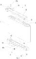
- Fig. 1 schematically shows an exploded structure of a power battery according to an embodiment of the disclosure.
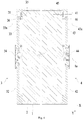
- Fig. 2 schematically shows a cross-sectional structure of a power battery according to a first embodiment of the disclosure.
- Fig. 3 schematically shows a cross-sectional structure of a power battery according to a second embodiment of the disclosure.
- Fig. 4 schematically shows a cross-sectional structure of a power battery according to a third embodiment of the disclosure.
- the power battery according to the embodiment of the disclosure includes a case 1, an electrode assembly 2 disposed in the case 1, and a first cap assembly 3 and a second cap assembly 4 both connected to the case 1.
- the case 1 includes two openings.
- the electrode assembly 2 is formed by winding a positive electrode sheet, a negative electrode sheet, and a separator disposed between the positive electrode sheet and the negative electrode sheet around a winding axis.
- the electrode assembly 2 includes two opposite ends along the winding axis. After the positive electrode sheet, the negative electrode sheet, and the separator disposed between the positive electrode sheet and the negative electrode sheet are wound, a spiral winding is formed at each end.
- the electrode assembly 2 is disposed in the case 1, and the two opposite ends of the electrode assembly 2 along the winding axis are respectively disposed corresponding to the two openings.
- the first cap assembly 3 covers one of the openings, and the second cap assembly 4 covers the other opening.
- the placement position of the first cap assembly 3 shown in Fig. 1 is taken as an object, an overall height direction of the first cap assembly 3 is taken as a height direction Y, an overall length direction of the first cap assembly 3 is taken as a length direction X, and a direction perpendicular to both the height direction Y and the length direction X is taken as a width direction (not marked in the drawings).
- the first cap assembly 3 includes a liquid injection hole 31 communicating with an interior of the case 1.
- the second cap assembly 4 includes a through hole 41 communicating with the interior of the case 1.
- the liquid injection hole 31 of the first cap assembly 3 and the through hole 41 of the second cap assembly 4 are located on a same side of a central axis 1a of the case 1.
- the central axis 1a of the case 1 refers to a central axis of the case 1 along the height direction Y. Two portions of the case 1 at two respective sides of the central axis 1a are substantially symmetrical with respect to the central axis 1a.
- the power battery can be placed horizontally (as shown in Figs.
- the first cap assembly 3 is in a vertical state, and then the liquid injection operation is performed.
- the liquid injection hole 31 disposed in the first cap assembly 3 is at a high position, and an electrolyte injected into the case 1 through the liquid injection hole 31 will flow along a parabolic trajectory due to its own gravity, which thereby effectively reduces a horizontal impact force on the end of the electrode assembly 2 and reduces a probability that a short circuit occurs between the positive electrode sheet and the negative electrode sheet due to insulation failure which may be caused by the displacement of the separator under the impact of the electrolyte; in another aspect, since the liquid injection hole 31 in the first cap assembly 3 and the through hole 41 in the second cap assembly 4 are located on the same side of the central axis 1a of the case 1, gas inside the case 1 can be discharged from the power battery through the through hole 41 when the liquid is injected through the liquid injection hole 31, which facilitates quick liquid injection; on the other hand, since the liquid injection hole 31 in the first cap assembly 3 and the through hole 41
- the through hole 41 disposed in the second cap assembly 4 is also at a high position, and the electrolyte discharged from the through hole 41 will flow along a parabolic trajectory due to its own gravity, which thereby effectively reduces a horizontal impact force on the end of the electrode assembly 2 and reduces a probability that a short circuit occurs between the positive electrode sheet and the negative electrode sheet due to insulation failure which may be caused by the displacement of the separator under the impact of the electrolyte.
- a projection of the liquid injection hole 31 in the height direction Y at least partially overlaps with a projection of the through hole 41 in the height direction Y.
- the liquid injection hole 31 and the through hole 41 may be approximately in the same horizontal position with each other, which helps to increase the liquid injection amount of the power battery.
- an axis of the liquid injection hole 31 coincides with an axis of the through hole 41, which can further increase the liquid injection amount of the power battery.
- a shape of the liquid injection hole 31 is the same as a shape of the through hole 41, which reduces the difficulty of manufacturing.
- the liquid injection hole 31 according to the embodiment is disposed at an end of the first cap assembly 3 along the length direction X.
- the through hole 41 is disposed at an end of the second cap assembly 4 along the length direction X. In this way, more electrolyte can be further injected into the case 1.
- the first cap assembly 3 includes a first cap plate 32 and a first electrode terminal 34 disposed in the first cap plate 32. Taps 21 are disposed at two opposite ends of the electrode assembly 2 respectively.
- the first cap plate 32 is connected to the case 1.
- the first electrode terminal 34 is electrically connected to one tab 21 on the electrode assembly 2.
- the liquid injection hole 31 is disposed in the first cap plate 32.
- the first cap plate 32 includes a top and a bottom opposite to each other in the height direction Y (the top and the bottom are based on the placement position as shown in Fig. 1 ).
- the liquid injection hole 31 includes a first inlet disposed at the top of the first cap plate 32 and a first outlet disposed at the bottom of the first cap plate 32.
- the second cap assembly 4 includes a second cap plate 42 and a second electrode terminal 44 disposed on the second cap plate 42.
- the second cap plate 42 is connected to the case 1.
- the second electrode terminal 44 is electrically connected to the other tab 21 on the electrode assembly 2.
- the through hole 41 is disposed in the second cap plate 42.
- the second cap plate 42 includes a top and a bottom opposite to each other in the height direction Y (the top and the bottom are based on the placement position as shown in Fig. 1 ).
- the through hole 41 includes a second inlet disposed at the top of the second cap plate 42 and a second outlet disposed at the bottom of the second cap plate 42.
- Fig. 2 schematically shows that the power battery is in a to-be-injected state.
- the electrolyte is injected from the first inlet of the liquid injection hole 31 and enters the case 1 from the first outlet.
- the electrolyte discharged from the first outlet will flow along a parabolic trajectory due to its own gravity, which thereby effectively reduces a horizontal impact force on the end of the electrode assembly 2.
- the through hole 41 can serve as an exhaust passage, and gas in the case 1 can be discharged through the through hole 41.
- the electrolyte may be injected from both the first inlet of the liquid injection hole 31 and the second inlet of the through hole 41 at the same time, which improves the efficiency of liquid injection.
- the liquid injection hole 31 is disposed at an end of the first cap plate 32 along the length direction X.
- the through hole 41 is disposed at an end of the second cap plate 42 along the length direction X.
- a projection of the liquid injection hole 31 in the height direction Y completely overlaps with a projection of the through hole 41 in the height direction Y. In this way, the injection amount of the electrolyte can be further increased.
- the first cap assembly 3 includes a first vent film 33.
- the first vent film 33 is disposed on the top of the first cap plate 32. After the liquid injection operation is finished, an edge of the first vent film 33 and the top of the first cap plate 32 form an annular joint, such that the first vent film 33 and the first cap plate 32 are hermetically connected.
- the first vent film 33 covers the first inlet of the liquid injection hole 31. After the electrolyte injection operation through the liquid injection hole 31 is finished, the first vent film 33 is hermetically connected to the top of the first cap plate 32, and the through hole 41 is also blocked to ensure that the interior of the power battery is in a sealed state. When the pressure inside the power battery is greater than a design pressure of the first vent film 33, the first vent film 33 will be broken, which thereby releases the internal pressure of the power battery and ensures the safety of the power battery.
- the first vent film 33 may have a strip-shaped structure or a circle-shaped structure.
- An axis of the first inlet of the liquid injection hole 31 is arranged offset from an axis 33a of the first vent film 33, and the axis 33a of the first vent film 33 is closer than the axis of the first inlet to the central axis 1a of the case 1.
- the axis 33a of the first vent film 33 refers to a central axis of the first vent film 33 along the height direction Y, and the first vent film 33 is substantially symmetrical with respect to the central axis 1a.
- a surface area of the first vent film 33 located within the annular joint is the effective force-bearing area of the first vent film 33.
- the gas discharged from the liquid injection hole 31 can apply a compressive force on the surface of the first vent film 33 located within the annular joint.
- a cross-sectional area of the liquid injection hole 31 refers to a projected area of the liquid injection hole 31 along the height direction Y. The larger the surface area of the first vent film 33 located within the annular joint, the lower the pressure required for its breaking. According to product requirements, the first vent film 33 is selected to have a suitable size to effectively ensure the safety of the power battery.
- the top of the first cap plate 32 includes a concave portion that is recessed toward the bottom.
- the liquid injection hole 31 is in communication with the recess, and the first vent film 33 is accommodated in the recess.
- the concave portion disposed at the top of the first cap plate 32 can position the first vent film 33 so as to quickly install and fix the first vent film 33 at a predetermined position on the first cap plate 32. Also, it is convenient to weld the joint formed between the first vent film 33 and the first cap plate 32, and it is beneficial to realize a quick connection between the first vent film 33 and the first cap plate 32. Furthermore, it can be avoided that the first vent film 33 disposed increases a thickness of the first cap plate 32.
- the second cap assembly 4 includes a second vent film 43.
- the second vent film 43 is disposed on the top of the second cap plate 42. After the liquid injection operation is finished, an edge of the second vent film 43 and the top of the second cap plate 42 form an annular joint, such that the second vent film 43 and the second cap plate 42 are hermetically connected.
- the second vent film 43 covers the second inlet of the through hole 41. After the electrolyte injection operation is finished, the second vent film 43 is hermetically connected to the top of the second cap plate 42 to seal the through hole 41 so as to ensure that the interior of the power battery is in a sealed state.
- the pressure inside the power battery is greater than a design pressure of the second vent film 43, the second vent film 43 will be broken, which thereby releases the internal pressure of the power battery and ensures the safety of the power battery.
- the second vent film 43 may have a strip shape or a circular shape.
- an axis of the second inlet of the through hole 41 is arranged offset from an axis 43a of the second vent film 43, and the axis 43a of the second vent film 43 is closer than the axis of the second inlet to the central axis 1a of the case 1.
- the axis 43a of the second vent film 43 refers to a central axis of the second vent film 43 along the height direction Y, and the second vent film 43 is substantially symmetrical with respect to the central axis 1a.
- a surface area of the second vent film 43 located within the annular joint is the effective force-bearing area of the second vent film 43.
- the gas discharged from the through hole 41 can apply a compressive force on the surface of the second vent film 43 located within the annular joint.
- a cross-sectional area of the through hole 41 refers to a projected area of the through hole 41 along the height direction Y. The larger the surface area of the second vent film 43 located within the annular joint, the lower the pressure required for its breaking. According to product requirements, the second vent film 43 is selected to have a suitable size to effectively ensure the safety of the power battery.
- the top of the second cap plate 42 includes a concave portion that is recessed toward the bottom.
- the through hole 41 is in communication with the recess, and the second vent film 43 is accommodated in the recess.
- the concave portion disposed at the top of the second cap plate 42 can position the second vent film 43 so as to quickly install and fix the second vent film 43 at a predetermined position on the second cap plate 42. Also, it is convenient to weld the joint formed between the second vent film 43 and the second cap plate 42, and it is beneficial to realize a quick connection between the second vent film 43 and the second cap plate 42. Furthermore, it can be avoided that the second vent film 43 disposed increases a thickness of the second cap plate 42.
- Fig. 3 shows that the power battery is in a to-be-injected state.
- the first cap assembly 3 according to the embodiment includes a first blocking member 35.
- the first blocking member 35 is disposed between the first outlet of the liquid injection hole 31 and the electrode assembly 2, and a projection of the first blocking member 35 in the height direction Y at least partially blocks the first outlet.
- the projection of the first blocking member 35 in the height direction Y completely blocks the first outlet of the liquid injection hole 31, such that all the electrolyte discharged from the first outlet of the liquid injection hole 31 has to turn a predetermined angle before entering the case 1, which further effectively prevents the electrolyte from impacting the end of the electrode assembly 2.
- the liquid injection hole 31 is disposed at the end of the first cap plate 32 along the length direction X.
- a first guide channel 36 is formed between the first blocking member 35 and the first cap plate 32.
- the first guide channel 36 communicates with the first outlet of the liquid injection hole 31.
- An outlet of the first guide channel 36 is oriented towards the central axis 1a of the case 1.
- the first guide channel 36 and the liquid injection hole 31 are at a predetermined angle.
- the electrolyte injected from the first inlet of the liquid injection hole 31 flows to the outlet of the liquid injection hole 31 along the height direction Y, and turns a predetermined angle due to obstruction of the first blocking member 35, and then is discharged through the first guide channel 36, such that the electrolyte will not continue to flow in the height direction Y when it is discharged from the first outlet of the liquid injection hole 31, and thus the flow rate of the electrolyte injected at high pressure will be slowed and the resultant impact force on the end of the electrode assembly 2 will be reduced.
- the predetermined angle formed between the first guide channel 36 and the liquid injection hole 31 is 90°, such that the electrolyte is injected into the liquid injection hole 31 along the height direction Y and discharged from the first guide channel 36 along the length direction X, which reduces the impact force of the electrolyte on the electrode assembly 2 along the height direction Y.
- the first blocking member 35 and the first cap plate 32 have an integrated structure, which improves a connection strength of them, and also facilitates one-time manufacturing, reducing manufacturing procedures and manufacturing difficulties.
- the first blocking member 35 has a plate-shaped structure.
- Fig. 4 shows that the power battery is in a to-be-injected state.
- the second cap assembly 4 according to the embodiment includes a second blocking member 45.
- the second blocking member 45 is disposed between the second outlet of the liquid injection hole 31 and the electrode assembly 2, and a projection of the second blocking member 45 in the height direction Y at least partially blocks the second outlet.
- the projection of the second blocking member 45 in the height direction Y completely blocks the second outlet of the through hole 41, such that all the electrolyte discharged from the second outlet of the through hole 41 has to turn a predetermined angle before entering the case 1, which further effectively prevents the electrolyte from impacting the end of the electrode assembly 2.
- the through hole 41 is disposed at the end of the second cap plate 42 along the length direction X.
- a second guide channel 46 is formed between the second blocking member 45 and the second cap plate 42.
- the second guide channel 46 communicates with the second outlet of the through hole 41.
- An outlet of the second guide channel 46 is oriented towards the central axis 1a of the case 1.
- the second guide channel 46 and the through hole 41 are at a predetermined angle.
- the electrolyte injected from the second inlet of the through hole 41 flows to the outlet of the through hole 41 along the height direction Y, and turns a predetermined angle due to obstruction of the second blocking member 45, and then is discharged through the second guide channel 46, such that the electrolyte will not continue to flow in the height direction Y when it is discharged from the second outlet of the through hole 41, and thus the flow rate of the electrolyte injected at high pressure will be slowed and the resultant impact force on the end of the electrode assembly 2 will be reduced.
- the predetermined angle formed between the second guide channel 46 and the through hole 41 is 90°, such that the electrolyte is injected into the through hole 41 along the height direction Y and discharged from the second guide channel 46 along the length direction X, which reduces the impact force of the electrolyte on the electrode assembly 2 along the height direction Y.
- the second blocking member 45 and the second cap plate 42 have an integrated structure, which improves a connection strength of them, and also facilitates one-time manufacturing, reducing manufacturing procedures and manufacturing difficulties.
- the second blocking member 45 has a plate-shaped structure.
- the impact force on the end of the electrode assembly 2 will be reduced, which thereby reduces a probability that a short circuit occurs between the positive electrode sheet and the negative electrode sheet which may be caused by the displacement of the separator included in the electrode assembly 2 under the impact of the electrolyte, improves a yield of the power battery after the liquid injection operation is finished, and also eliminates hidden dangers of the power battery and ensures the safety in the subsequent use.
- An embodiment of the disclosure also provides a battery module.
- the battery module according to the embodiment includes a plurality of power batteries according to the above embodiments.
- the power batteries are arranged side by side in one direction. Since the power battery according to the embodiment has good safety performance, it can be ensured that the battery module as a whole has good safety performance.
Landscapes
- Chemical & Material Sciences (AREA)
- Chemical Kinetics & Catalysis (AREA)
- Electrochemistry (AREA)
- General Chemical & Material Sciences (AREA)
- Engineering & Computer Science (AREA)
- Manufacturing & Machinery (AREA)
- Filling, Topping-Up Batteries (AREA)
Applications Claiming Priority (2)
| Application Number | Priority Date | Filing Date | Title |
|---|---|---|---|
| CN201820179736.3U CN207800781U (zh) | 2018-02-01 | 2018-02-01 | 动力电池以及电池模组 |
| PCT/CN2018/083386 WO2019148664A1 (fr) | 2018-02-01 | 2018-04-17 | Batterie d'alimentation et module de batterie |
Publications (3)
| Publication Number | Publication Date |
|---|---|
| EP3748754A1 true EP3748754A1 (fr) | 2020-12-09 |
| EP3748754A4 EP3748754A4 (fr) | 2021-04-07 |
| EP3748754B1 EP3748754B1 (fr) | 2022-06-15 |
Family
ID=63267884
Family Applications (1)
| Application Number | Title | Priority Date | Filing Date |
|---|---|---|---|
| EP18903363.2A Active EP3748754B1 (fr) | 2018-02-01 | 2018-04-17 | Batterie d'alimentation et module de batterie |
Country Status (5)
| Country | Link |
|---|---|
| US (2) | US11489221B2 (fr) |
| EP (1) | EP3748754B1 (fr) |
| CN (1) | CN207800781U (fr) |
| ES (1) | ES2922198T3 (fr) |
| WO (1) | WO2019148664A1 (fr) |
Cited By (1)
| Publication number | Priority date | Publication date | Assignee | Title |
|---|---|---|---|---|
| WO2025108966A1 (fr) * | 2023-11-24 | 2025-05-30 | Carl Freudenberg Kg | Cellule prismatique à deux ouvertures |
Families Citing this family (7)
| Publication number | Priority date | Publication date | Assignee | Title |
|---|---|---|---|---|
| CN110911723B (zh) * | 2018-09-18 | 2024-10-18 | 宁德时代新能源科技股份有限公司 | 二次电池 |
| US12255299B2 (en) * | 2019-02-13 | 2025-03-18 | Lg Energy Solution, Ltd. | Battery module, manufacturing method thereof and battery pack including battery module |
| CN111354919A (zh) * | 2020-04-01 | 2020-06-30 | 湖北亿纬动力有限公司 | 一种电池、电池的注液方法及电池模组 |
| EP4336629A3 (fr) * | 2022-09-07 | 2024-09-11 | SK On Co., Ltd. | Cellule de batterie |
| US12191507B2 (en) * | 2022-09-07 | 2025-01-07 | Sk On Co., Ltd. | Battery cell |
| CN221080157U (zh) * | 2023-09-22 | 2024-06-04 | 惠州亿纬动力电池有限公司 | 外壳组件以及电池 |
| JP2025068352A (ja) | 2023-10-16 | 2025-04-28 | プライムプラネットエナジー&ソリューションズ株式会社 | 二次電池 |
Family Cites Families (15)
| Publication number | Priority date | Publication date | Assignee | Title |
|---|---|---|---|---|
| US5849431A (en) * | 1995-09-27 | 1998-12-15 | Sony Corporation | High capacity secondary battery of jelly roll type |
| US6610444B2 (en) * | 2000-09-29 | 2003-08-26 | Sanyo Electric Co., Ltd. | Secondary cell with non-rotatable terminal member |
| JP4225272B2 (ja) * | 2004-11-22 | 2009-02-18 | 日本電気株式会社 | 電池及び電池パック |
| CN101651187A (zh) * | 2008-08-15 | 2010-02-17 | 深圳市比克电池有限公司 | 一种电池极耳与盖板的连接结构 |
| JP2010086776A (ja) | 2008-09-30 | 2010-04-15 | Toshiba Corp | 密閉型二次電池および密閉型二次電池の製造方法 |
| CN201340879Y (zh) * | 2008-12-23 | 2009-11-04 | 天津力神电池股份有限公司 | 一种圆形锂离子电池结构 |
| CN104094450B (zh) * | 2012-02-22 | 2016-11-16 | 日立汽车系统株式会社 | 方形二次电池 |
| CN103887453B (zh) * | 2012-12-24 | 2016-03-09 | 惠州比亚迪电池有限公司 | 一种锂离子电池封口结构及其锂离子电池 |
| JP6191882B2 (ja) * | 2014-12-05 | 2017-09-06 | トヨタ自動車株式会社 | 密閉型電池およびその製造方法 |
| KR101791427B1 (ko) * | 2014-12-18 | 2017-10-30 | 주식회사 엘지화학 | 내면에 전해액 유도부가 형성된 캡 플레이트를 포함하는 전지팩 |
| KR102572693B1 (ko) * | 2015-10-02 | 2023-08-31 | 삼성에스디아이 주식회사 | 이차 전지 |
| KR102633271B1 (ko) * | 2016-01-04 | 2024-02-05 | 삼성에스디아이 주식회사 | 이차 전지 |
| US10868337B2 (en) * | 2016-03-08 | 2020-12-15 | Beijing Hawaga Power Storage Technology Company Ltd | Cell-core for lithium slurry battery, and lithium slurry battery module |
| CN207800664U (zh) | 2018-02-01 | 2018-08-31 | 宁德时代新能源科技股份有限公司 | 顶盖组件以及动力电池 |
| CN108461700B (zh) | 2018-02-02 | 2024-01-02 | 惠州拓邦电气技术有限公司 | 一种高倍率全极耳型锂电池及其制备方法 |
-
2018
- 2018-02-01 CN CN201820179736.3U patent/CN207800781U/zh active Active
- 2018-04-17 WO PCT/CN2018/083386 patent/WO2019148664A1/fr not_active Ceased
- 2018-04-17 US US16/965,289 patent/US11489221B2/en active Active
- 2018-04-17 ES ES18903363T patent/ES2922198T3/es active Active
- 2018-04-17 EP EP18903363.2A patent/EP3748754B1/fr active Active
-
2022
- 2022-09-28 US US17/954,358 patent/US12062798B2/en active Active
Cited By (1)
| Publication number | Priority date | Publication date | Assignee | Title |
|---|---|---|---|---|
| WO2025108966A1 (fr) * | 2023-11-24 | 2025-05-30 | Carl Freudenberg Kg | Cellule prismatique à deux ouvertures |
Also Published As
| Publication number | Publication date |
|---|---|
| WO2019148664A1 (fr) | 2019-08-08 |
| US12062798B2 (en) | 2024-08-13 |
| ES2922198T3 (es) | 2022-09-09 |
| EP3748754A4 (fr) | 2021-04-07 |
| US20230019890A1 (en) | 2023-01-19 |
| US11489221B2 (en) | 2022-11-01 |
| EP3748754B1 (fr) | 2022-06-15 |
| US20210074961A1 (en) | 2021-03-11 |
| CN207800781U (zh) | 2018-08-31 |
Similar Documents
| Publication | Publication Date | Title |
|---|---|---|
| US12062798B2 (en) | Power battery and battery module | |
| CN207800664U (zh) | 顶盖组件以及动力电池 | |
| EP3790072B1 (fr) | Ensemble couvercle supérieur de batterie secondaire et batterie secondaire | |
| US20250329896A1 (en) | Battery cell and electrical device | |
| US9166219B2 (en) | Electric storage device | |
| EP3726626A1 (fr) | Batterie auxiliaire et module de batterie | |
| EP4415155B1 (fr) | Ensemble plastique inférieur, appareil de stockage d'énergie et dispositif électrique | |
| EP3598523B1 (fr) | Ensemble de couvercle de batterie secondaire, batterie secondaire et véhicule | |
| EP4462579A1 (fr) | Soupape antidéflagrante, couvercle de batterie et batterie | |
| US20250038347A1 (en) | Battery | |
| EP3544090B1 (fr) | Ensemble capot supérieur pour batterie et batterie de puissance ayant la même puissance | |
| CN220086334U (zh) | 单通圆柱电池 | |
| CN116845505B (zh) | 一种连接片及电池 | |
| KR100696777B1 (ko) | 리튬 이온 이차 전지 | |
| KR20210004570A (ko) | 캡 어셈블리 및 이를 포함하는 원통형 이차전지 | |
| CN119153910A (zh) | 一种二次电池 | |
| CN217788750U (zh) | 电池盖板组件和具有其的电池 | |
| CN222190952U (zh) | 盖板组件及电芯 | |
| CN222146529U (zh) | 一种绝缘垫片及电池 | |
| CN221126072U (zh) | 电池及电池装置 | |
| CN223066327U (zh) | 电池和具有其的电池包 | |
| CN116845504B (zh) | 一种连接片及电池 | |
| CN220341435U (zh) | 一种电池壳体及电池 | |
| CN222233740U (zh) | 电池端盖、电池及模组 | |
| CN121307351A (zh) | 电池盖板及电池 |
Legal Events
| Date | Code | Title | Description |
|---|---|---|---|
| STAA | Information on the status of an ep patent application or granted ep patent |
Free format text: STATUS: THE INTERNATIONAL PUBLICATION HAS BEEN MADE |
|
| PUAI | Public reference made under article 153(3) epc to a published international application that has entered the european phase |
Free format text: ORIGINAL CODE: 0009012 |
|
| STAA | Information on the status of an ep patent application or granted ep patent |
Free format text: STATUS: REQUEST FOR EXAMINATION WAS MADE |
|
| 17P | Request for examination filed |
Effective date: 20200728 |
|
| AK | Designated contracting states |
Kind code of ref document: A1 Designated state(s): AL AT BE BG CH CY CZ DE DK EE ES FI FR GB GR HR HU IE IS IT LI LT LU LV MC MK MT NL NO PL PT RO RS SE SI SK SM TR |
|
| AX | Request for extension of the european patent |
Extension state: BA ME |
|
| A4 | Supplementary search report drawn up and despatched |
Effective date: 20210305 |
|
| RIC1 | Information provided on ipc code assigned before grant |
Ipc: H01M 10/04 20060101AFI20210301BHEP |
|
| DAV | Request for validation of the european patent (deleted) | ||
| DAX | Request for extension of the european patent (deleted) | ||
| REG | Reference to a national code |
Ref country code: DE Ref legal event code: R079 Ref document number: 602018036900 Country of ref document: DE Free format text: PREVIOUS MAIN CLASS: H01M0010040000 Ipc: H01M0050600000 |
|
| RIC1 | Information provided on ipc code assigned before grant |
Ipc: H01M 10/04 20060101ALI20211105BHEP Ipc: H01M 50/15 20210101ALI20211105BHEP Ipc: H01M 50/103 20210101ALI20211105BHEP Ipc: H01M 50/60 20210101AFI20211105BHEP |
|
| GRAP | Despatch of communication of intention to grant a patent |
Free format text: ORIGINAL CODE: EPIDOSNIGR1 |
|
| STAA | Information on the status of an ep patent application or granted ep patent |
Free format text: STATUS: GRANT OF PATENT IS INTENDED |
|
| INTG | Intention to grant announced |
Effective date: 20211217 |
|
| GRAJ | Information related to disapproval of communication of intention to grant by the applicant or resumption of examination proceedings by the epo deleted |
Free format text: ORIGINAL CODE: EPIDOSDIGR1 |
|
| STAA | Information on the status of an ep patent application or granted ep patent |
Free format text: STATUS: REQUEST FOR EXAMINATION WAS MADE |
|
| INTC | Intention to grant announced (deleted) | ||
| RAP3 | Party data changed (applicant data changed or rights of an application transferred) |
Owner name: CONTEMPORARY AMPEREX TECHNOLOGY CO., LIMITED |
|
| GRAP | Despatch of communication of intention to grant a patent |
Free format text: ORIGINAL CODE: EPIDOSNIGR1 |
|
| STAA | Information on the status of an ep patent application or granted ep patent |
Free format text: STATUS: GRANT OF PATENT IS INTENDED |
|
| INTG | Intention to grant announced |
Effective date: 20220411 |
|
| GRAS | Grant fee paid |
Free format text: ORIGINAL CODE: EPIDOSNIGR3 |
|
| GRAA | (expected) grant |
Free format text: ORIGINAL CODE: 0009210 |
|
| STAA | Information on the status of an ep patent application or granted ep patent |
Free format text: STATUS: THE PATENT HAS BEEN GRANTED |
|
| AK | Designated contracting states |
Kind code of ref document: B1 Designated state(s): AL AT BE BG CH CY CZ DE DK EE ES FI FR GB GR HR HU IE IS IT LI LT LU LV MC MK MT NL NO PL PT RO RS SE SI SK SM TR |
|
| REG | Reference to a national code |
Ref country code: CH Ref legal event code: EP Ref country code: GB Ref legal event code: FG4D |
|
| REG | Reference to a national code |
Ref country code: IE Ref legal event code: FG4D |
|
| REG | Reference to a national code |
Ref country code: DE Ref legal event code: R096 Ref document number: 602018036900 Country of ref document: DE |
|
| REG | Reference to a national code |
Ref country code: AT Ref legal event code: REF Ref document number: 1498938 Country of ref document: AT Kind code of ref document: T Effective date: 20220715 |
|
| REG | Reference to a national code |
Ref country code: ES Ref legal event code: FG2A Ref document number: 2922198 Country of ref document: ES Kind code of ref document: T3 Effective date: 20220909 |
|
| REG | Reference to a national code |
Ref country code: LT Ref legal event code: MG9D |
|
| REG | Reference to a national code |
Ref country code: NL Ref legal event code: MP Effective date: 20220615 |
|
| PG25 | Lapsed in a contracting state [announced via postgrant information from national office to epo] |
Ref country code: SE Free format text: LAPSE BECAUSE OF FAILURE TO SUBMIT A TRANSLATION OF THE DESCRIPTION OR TO PAY THE FEE WITHIN THE PRESCRIBED TIME-LIMIT Effective date: 20220615 Ref country code: NO Free format text: LAPSE BECAUSE OF FAILURE TO SUBMIT A TRANSLATION OF THE DESCRIPTION OR TO PAY THE FEE WITHIN THE PRESCRIBED TIME-LIMIT Effective date: 20220915 Ref country code: LT Free format text: LAPSE BECAUSE OF FAILURE TO SUBMIT A TRANSLATION OF THE DESCRIPTION OR TO PAY THE FEE WITHIN THE PRESCRIBED TIME-LIMIT Effective date: 20220615 Ref country code: HR Free format text: LAPSE BECAUSE OF FAILURE TO SUBMIT A TRANSLATION OF THE DESCRIPTION OR TO PAY THE FEE WITHIN THE PRESCRIBED TIME-LIMIT Effective date: 20220615 Ref country code: GR Free format text: LAPSE BECAUSE OF FAILURE TO SUBMIT A TRANSLATION OF THE DESCRIPTION OR TO PAY THE FEE WITHIN THE PRESCRIBED TIME-LIMIT Effective date: 20220916 Ref country code: FI Free format text: LAPSE BECAUSE OF FAILURE TO SUBMIT A TRANSLATION OF THE DESCRIPTION OR TO PAY THE FEE WITHIN THE PRESCRIBED TIME-LIMIT Effective date: 20220615 Ref country code: BG Free format text: LAPSE BECAUSE OF FAILURE TO SUBMIT A TRANSLATION OF THE DESCRIPTION OR TO PAY THE FEE WITHIN THE PRESCRIBED TIME-LIMIT Effective date: 20220915 |
|
| REG | Reference to a national code |
Ref country code: AT Ref legal event code: MK05 Ref document number: 1498938 Country of ref document: AT Kind code of ref document: T Effective date: 20220615 |
|
| PG25 | Lapsed in a contracting state [announced via postgrant information from national office to epo] |
Ref country code: RS Free format text: LAPSE BECAUSE OF FAILURE TO SUBMIT A TRANSLATION OF THE DESCRIPTION OR TO PAY THE FEE WITHIN THE PRESCRIBED TIME-LIMIT Effective date: 20220615 Ref country code: LV Free format text: LAPSE BECAUSE OF FAILURE TO SUBMIT A TRANSLATION OF THE DESCRIPTION OR TO PAY THE FEE WITHIN THE PRESCRIBED TIME-LIMIT Effective date: 20220615 |
|
| PG25 | Lapsed in a contracting state [announced via postgrant information from national office to epo] |
Ref country code: NL Free format text: LAPSE BECAUSE OF FAILURE TO SUBMIT A TRANSLATION OF THE DESCRIPTION OR TO PAY THE FEE WITHIN THE PRESCRIBED TIME-LIMIT Effective date: 20220615 |
|
| PG25 | Lapsed in a contracting state [announced via postgrant information from national office to epo] |
Ref country code: SM Free format text: LAPSE BECAUSE OF FAILURE TO SUBMIT A TRANSLATION OF THE DESCRIPTION OR TO PAY THE FEE WITHIN THE PRESCRIBED TIME-LIMIT Effective date: 20220615 Ref country code: SK Free format text: LAPSE BECAUSE OF FAILURE TO SUBMIT A TRANSLATION OF THE DESCRIPTION OR TO PAY THE FEE WITHIN THE PRESCRIBED TIME-LIMIT Effective date: 20220615 Ref country code: RO Free format text: LAPSE BECAUSE OF FAILURE TO SUBMIT A TRANSLATION OF THE DESCRIPTION OR TO PAY THE FEE WITHIN THE PRESCRIBED TIME-LIMIT Effective date: 20220615 Ref country code: PT Free format text: LAPSE BECAUSE OF FAILURE TO SUBMIT A TRANSLATION OF THE DESCRIPTION OR TO PAY THE FEE WITHIN THE PRESCRIBED TIME-LIMIT Effective date: 20221017 Ref country code: EE Free format text: LAPSE BECAUSE OF FAILURE TO SUBMIT A TRANSLATION OF THE DESCRIPTION OR TO PAY THE FEE WITHIN THE PRESCRIBED TIME-LIMIT Effective date: 20220615 Ref country code: CZ Free format text: LAPSE BECAUSE OF FAILURE TO SUBMIT A TRANSLATION OF THE DESCRIPTION OR TO PAY THE FEE WITHIN THE PRESCRIBED TIME-LIMIT Effective date: 20220615 Ref country code: AT Free format text: LAPSE BECAUSE OF FAILURE TO SUBMIT A TRANSLATION OF THE DESCRIPTION OR TO PAY THE FEE WITHIN THE PRESCRIBED TIME-LIMIT Effective date: 20220615 |
|
| PG25 | Lapsed in a contracting state [announced via postgrant information from national office to epo] |
Ref country code: PL Free format text: LAPSE BECAUSE OF FAILURE TO SUBMIT A TRANSLATION OF THE DESCRIPTION OR TO PAY THE FEE WITHIN THE PRESCRIBED TIME-LIMIT Effective date: 20220615 Ref country code: IS Free format text: LAPSE BECAUSE OF FAILURE TO SUBMIT A TRANSLATION OF THE DESCRIPTION OR TO PAY THE FEE WITHIN THE PRESCRIBED TIME-LIMIT Effective date: 20221015 |
|
| REG | Reference to a national code |
Ref country code: DE Ref legal event code: R097 Ref document number: 602018036900 Country of ref document: DE |
|
| PG25 | Lapsed in a contracting state [announced via postgrant information from national office to epo] |
Ref country code: AL Free format text: LAPSE BECAUSE OF FAILURE TO SUBMIT A TRANSLATION OF THE DESCRIPTION OR TO PAY THE FEE WITHIN THE PRESCRIBED TIME-LIMIT Effective date: 20220615 |
|
| PLBE | No opposition filed within time limit |
Free format text: ORIGINAL CODE: 0009261 |
|
| STAA | Information on the status of an ep patent application or granted ep patent |
Free format text: STATUS: NO OPPOSITION FILED WITHIN TIME LIMIT |
|
| PG25 | Lapsed in a contracting state [announced via postgrant information from national office to epo] |
Ref country code: DK Free format text: LAPSE BECAUSE OF FAILURE TO SUBMIT A TRANSLATION OF THE DESCRIPTION OR TO PAY THE FEE WITHIN THE PRESCRIBED TIME-LIMIT Effective date: 20220615 |
|
| 26N | No opposition filed |
Effective date: 20230316 |
|
| PG25 | Lapsed in a contracting state [announced via postgrant information from national office to epo] |
Ref country code: SI Free format text: LAPSE BECAUSE OF FAILURE TO SUBMIT A TRANSLATION OF THE DESCRIPTION OR TO PAY THE FEE WITHIN THE PRESCRIBED TIME-LIMIT Effective date: 20220615 |
|
| P01 | Opt-out of the competence of the unified patent court (upc) registered |
Effective date: 20230516 |
|
| REG | Reference to a national code |
Ref country code: CH Ref legal event code: PL |
|
| PG25 | Lapsed in a contracting state [announced via postgrant information from national office to epo] |
Ref country code: LU Free format text: LAPSE BECAUSE OF NON-PAYMENT OF DUE FEES Effective date: 20230417 |
|
| REG | Reference to a national code |
Ref country code: BE Ref legal event code: MM Effective date: 20230430 |
|
| PG25 | Lapsed in a contracting state [announced via postgrant information from national office to epo] |
Ref country code: MC Free format text: LAPSE BECAUSE OF FAILURE TO SUBMIT A TRANSLATION OF THE DESCRIPTION OR TO PAY THE FEE WITHIN THE PRESCRIBED TIME-LIMIT Effective date: 20220615 |
|
| PG25 | Lapsed in a contracting state [announced via postgrant information from national office to epo] |
Ref country code: MC Free format text: LAPSE BECAUSE OF FAILURE TO SUBMIT A TRANSLATION OF THE DESCRIPTION OR TO PAY THE FEE WITHIN THE PRESCRIBED TIME-LIMIT Effective date: 20220615 Ref country code: LI Free format text: LAPSE BECAUSE OF NON-PAYMENT OF DUE FEES Effective date: 20230430 Ref country code: CH Free format text: LAPSE BECAUSE OF NON-PAYMENT OF DUE FEES Effective date: 20230430 |
|
| REG | Reference to a national code |
Ref country code: IE Ref legal event code: MM4A |
|
| PG25 | Lapsed in a contracting state [announced via postgrant information from national office to epo] |
Ref country code: BE Free format text: LAPSE BECAUSE OF NON-PAYMENT OF DUE FEES Effective date: 20230430 |
|
| PG25 | Lapsed in a contracting state [announced via postgrant information from national office to epo] |
Ref country code: IE Free format text: LAPSE BECAUSE OF NON-PAYMENT OF DUE FEES Effective date: 20230417 |
|
| PG25 | Lapsed in a contracting state [announced via postgrant information from national office to epo] |
Ref country code: IE Free format text: LAPSE BECAUSE OF NON-PAYMENT OF DUE FEES Effective date: 20230417 |
|
| REG | Reference to a national code |
Ref country code: DE Ref legal event code: R081 Ref document number: 602018036900 Country of ref document: DE Owner name: CONTEMPORARY AMPEREX TECHNOLOGY (HONG KONG) LI, HK Free format text: FORMER OWNER: CONTEMPORARY AMPEREX TECHNOLOGY CO., LTD., NINGDE CITY, FUJIAN, CN |
|
| REG | Reference to a national code |
Ref country code: GB Ref legal event code: 732E Free format text: REGISTERED BETWEEN 20240829 AND 20240904 |
|
| PG25 | Lapsed in a contracting state [announced via postgrant information from national office to epo] |
Ref country code: BG Free format text: LAPSE BECAUSE OF FAILURE TO SUBMIT A TRANSLATION OF THE DESCRIPTION OR TO PAY THE FEE WITHIN THE PRESCRIBED TIME-LIMIT Effective date: 20220615 |
|
| PG25 | Lapsed in a contracting state [announced via postgrant information from national office to epo] |
Ref country code: BG Free format text: LAPSE BECAUSE OF FAILURE TO SUBMIT A TRANSLATION OF THE DESCRIPTION OR TO PAY THE FEE WITHIN THE PRESCRIBED TIME-LIMIT Effective date: 20220615 |
|
| REG | Reference to a national code |
Ref country code: ES Ref legal event code: PC2A Owner name: CONTEMPORARY AMPEREX TECHNOLOGY (HONG KONG) LIMITED Effective date: 20241127 |
|
| PGFP | Annual fee paid to national office [announced via postgrant information from national office to epo] |
Ref country code: DE Payment date: 20250218 Year of fee payment: 8 |
|
| PGFP | Annual fee paid to national office [announced via postgrant information from national office to epo] |
Ref country code: ES Payment date: 20250508 Year of fee payment: 8 |
|
| PG25 | Lapsed in a contracting state [announced via postgrant information from national office to epo] |
Ref country code: CY Free format text: LAPSE BECAUSE OF FAILURE TO SUBMIT A TRANSLATION OF THE DESCRIPTION OR TO PAY THE FEE WITHIN THE PRESCRIBED TIME-LIMIT; INVALID AB INITIO Effective date: 20180417 |
|
| PG25 | Lapsed in a contracting state [announced via postgrant information from national office to epo] |
Ref country code: HU Free format text: LAPSE BECAUSE OF FAILURE TO SUBMIT A TRANSLATION OF THE DESCRIPTION OR TO PAY THE FEE WITHIN THE PRESCRIBED TIME-LIMIT; INVALID AB INITIO Effective date: 20180417 |
|
| PG25 | Lapsed in a contracting state [announced via postgrant information from national office to epo] |
Ref country code: TR Free format text: LAPSE BECAUSE OF FAILURE TO SUBMIT A TRANSLATION OF THE DESCRIPTION OR TO PAY THE FEE WITHIN THE PRESCRIBED TIME-LIMIT Effective date: 20220615 |
|
| PGFP | Annual fee paid to national office [announced via postgrant information from national office to epo] |
Ref country code: GB Payment date: 20260303 Year of fee payment: 9 |
|
| PGFP | Annual fee paid to national office [announced via postgrant information from national office to epo] |
Ref country code: IT Payment date: 20260320 Year of fee payment: 9 |
|
| PGFP | Annual fee paid to national office [announced via postgrant information from national office to epo] |
Ref country code: FR Payment date: 20260223 Year of fee payment: 9 |