EP3748792B1 - Appareil de commutation à isolation gazeuse - Google Patents
Appareil de commutation à isolation gazeuse Download PDFInfo
- Publication number
- EP3748792B1 EP3748792B1 EP18903089.3A EP18903089A EP3748792B1 EP 3748792 B1 EP3748792 B1 EP 3748792B1 EP 18903089 A EP18903089 A EP 18903089A EP 3748792 B1 EP3748792 B1 EP 3748792B1
- Authority
- EP
- European Patent Office
- Prior art keywords
- main body
- gas
- insulated switchgear
- bus line
- line
- Prior art date
- Legal status (The legal status is an assumption and is not a legal conclusion. Google has not performed a legal analysis and makes no representation as to the accuracy of the status listed.)
- Active
Links
Images


Classifications
-
- H—ELECTRICITY
- H02—GENERATION; CONVERSION OR DISTRIBUTION OF ELECTRIC POWER
- H02B—BOARDS, SUBSTATIONS OR SWITCHING ARRANGEMENTS FOR THE SUPPLY OR DISTRIBUTION OF ELECTRIC POWER
- H02B13/00—Arrangement of switchgear in which switches are enclosed in, or structurally associated with, a casing, e.g. cubicle
- H02B13/02—Arrangement of switchgear in which switches are enclosed in, or structurally associated with, a casing, e.g. cubicle with metal casing
- H02B13/035—Gas-insulated switchgear
- H02B13/045—Details of casing, e.g. gas tightness
-
- H—ELECTRICITY
- H01—ELECTRIC ELEMENTS
- H01H—ELECTRIC SWITCHES; RELAYS; SELECTORS; EMERGENCY PROTECTIVE DEVICES
- H01H31/00—Air-break switches for high tension without arc-extinguishing or arc-preventing means
- H01H31/26—Air-break switches for high tension without arc-extinguishing or arc-preventing means with movable contact that remains electrically connected to one line in open position of switch
-
- H—ELECTRICITY
- H02—GENERATION; CONVERSION OR DISTRIBUTION OF ELECTRIC POWER
- H02B—BOARDS, SUBSTATIONS OR SWITCHING ARRANGEMENTS FOR THE SUPPLY OR DISTRIBUTION OF ELECTRIC POWER
- H02B13/00—Arrangement of switchgear in which switches are enclosed in, or structurally associated with, a casing, e.g. cubicle
- H02B13/02—Arrangement of switchgear in which switches are enclosed in, or structurally associated with, a casing, e.g. cubicle with metal casing
- H02B13/035—Gas-insulated switchgear
- H02B13/0358—Connections to in or out conductors
-
- H—ELECTRICITY
- H02—GENERATION; CONVERSION OR DISTRIBUTION OF ELECTRIC POWER
- H02B—BOARDS, SUBSTATIONS OR SWITCHING ARRANGEMENTS FOR THE SUPPLY OR DISTRIBUTION OF ELECTRIC POWER
- H02B13/00—Arrangement of switchgear in which switches are enclosed in, or structurally associated with, a casing, e.g. cubicle
- H02B13/02—Arrangement of switchgear in which switches are enclosed in, or structurally associated with, a casing, e.g. cubicle with metal casing
- H02B13/035—Gas-insulated switchgear
- H02B13/075—Earthing arrangements
Definitions
- the present invention relates to a gas-insulated switchgear in which a conductor is arranged in a tank with insulating gas enclosed therein.
- a tank of a gas-insulated switchgear includes a cylindrical main body.
- a bus line that is a conductor of a main circuit is arranged coaxially with a main body axis that is a center line of the main body of the tank.
- a branch pipe having a central axis that is perpendicular to the main body axis is branched from the main body, and the branch line is arranged in the branch pipe.
- a grounding switch that is one of structures for allowing a branch line to branch from a bus line.
- This grounding switch is a device having a function of grounding a main circuit. Because the branch line branching from a bus line of a gas-insulated switchgear extends in a perpendicular direction to the main body axis, a direction in which the branch line extends can be changed by rotating the main body around the main body axis. With this configuration, even when there is an obstacle, it is possible to avoid the obstacle in a direction of rotation around the main body axis.
- Patent Literature 2 relates to a method and an apparatus for forming a joint in a high voltage gas insulated electrical system wherein an outer spherical joint member surrounds an inner spherical joint member which is supported from only one of the inner housing conductors.
- the inner housing conductor which supports the inner sphere is supported where it extends into the outer housing sphere from a circular insulating member.
- the circulating insulating spacer and support is rigidly connected to a flanged opening formed on the outer housing sphere.
- the inner sphere which is rigidly supported is provided with a plurality of sliding contact openings for engaging other inner conductors of the additional bus sections to be joined.
- the outer spherical housing is formed from two hemispheres each of which has an opening formed therein.
- the plane defined by the opening into the hemisphere is transverse to the plane defined by the free ends of the hemisphere.
- Patent Literature 3 relates to a disconnect switch and grounding apparatus therefor particularly adapted for use in gas insulated substations.
- the disconnect switch comprises a chamber having a pair of electrical conductors entering the chamber. Supporting the conductors and insulating them from contact with the chamber itself are insulators, which may be sealingly placed so as to prohibit the escape of the gas.
- a fixed contact member electrically attached to the first of the pair of conductors and a movable contact member is electrically attached to the second pair of conductors.
- a movement mechanism to move the movable contact members so as to make and break contact with the fixed contact member.
- the movement mechanism comprises a linkage having two links, the first link attached at one end to the movable contact member and the other end connected to the second link, the other end of the second link being connected to a shaft member.
- the shaft member sealingly extends through the wall of the chamber having attached to it on the outside of the chamber a handle for causing the shaft to rotate. The shaft upon rotation engages the linkage causing the movable contact member to make or break contact with the fixed contact member and respectively the ground strip to move away from or come in contact with the wall of the chamber.
- Patent Literature 4 relates to an elbow structure for high voltage compressed-gas-insulated conductors.
- the present invention has been achieved in view of the above problems, and an object of the present invention is to provide a gas-insulated switchgear having highly flexible layout.
- a gas-insulated switchgear comprising: a main circuit conductor forming a bus line; a tank having a tubular main body in which the bus line is arranged at its center; and a branch pipe connected to the main body, in which a branch line branching from the bus line is provided.
- a surface of the main body is spherical, and has an opening that allows the branch line to pass therethrough on the surface.
- the branch line is a movable contact of a grounding switch.
- a fixed electrode of the grounding switch is provided at a section midway of the bus line.
- the movable contact has a circular cross-section.
- the fixed electrode is spherical, portions of the fixed electrode to be connected to the bus line are flat, and a circular hole that allows insertion of the movable contact thereinto is formed in a spherical portion of the fixed electrode.
- FIGS. 4 and 5 illustrate a configuration of a gas-insulated switchgear according to an embodiment of the claimed invention.
- FIGS. 1 to 3 illustrate a configuration of a gas-insulated switchgear according to a first illustrative example assisting to understand the configuration of the gas-insulated switchgear according to the embodiment of the claimed invention.
- FIGS. 1 and 2 are cross-sectional views illustrating a configuration of a gas-insulated switchgear according to the first illustrative example each including a main body axis.
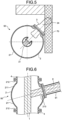
- FIG. 3 is a cross-sectional view taken along a line perpendicular to the main body axis of the gas-insulated switchgear according to the first illustrative example.
- FIG. 1 to 3 illustrate a configuration of a gas-insulated switchgear according to a first illustrative example assisting to understand the configuration of the gas-insulated switchgear according to the embodiment of the claimed invention.
- FIGS. 1 and 2 are cross-sectional views illustrating a configuration of
- a gas-insulated switchgear 50 includes a main circuit conductor 1 forming a bus line, a tank 2 including a tubular main body 21, in which the bus line arranged at the center, and a grounding switch 3.
- the central axis of the main body 21 is described as "main body axis". Insulating gas is enclosed in the tank 2.
- the grounding switch 3 includes a fixed electrode 31 that is interposed between main circuit conductors 1 and forms a portion of the bus line, a movable contact 32 that is arranged to face to the fixed electrode 31, a link mechanism 33 that moves the movable contact 32, and a grounding-switch tank 34 that covers the movable contact 32 and the link mechanism 33.
- the movable contact 32 has a circular cross-section that is perpendicular to its moving direction.
- the fixed electrode 31 has a spherical shape in which portions that are connected to the main circuit conductors 1 are flat, and the fixed electrode 31 is in surface-contact with the main circuit conductors 1.
- a circular hole 311 is formed in a portion of the fixed electrode 31 having a spherical surface, and the movable contact 32 is to be inserted into the circular hole 311.
- a stator contact 312 is provided in the hole 311.
- the fixed electrode 31 and the movable contact 32 are apart from each other; however, when a main circuit is grounded, the link mechanism 33 is driven by a drive mechanism provided outside the grounding-switch tank 34, and the movable contact 32 is moved to be inserted into the fixed electrode 31 through the hole 311, so that the movable contact 32 becomes a branch line branching from the bus line. Therefore, the grounding-switch tank 34 is a branch pipe that surrounds the branch line branching from the bus line.
- the main body 21 has a spherical tubular surface 211, and has flanges 212 at both end thereof for connection to adjacent tanks 4.
- An opening 213 is formed in the tubular surface 211 of the main body 21, to which the grounding-switch tank 34 is connected.
- the movable contact 32 serving as a branch line protrudes out of the tank 2 through the opening 213.
- the direction the opening 213 is facing is inclined at an angle Z with respect to the main body axis. Therefore, the main circuit conductors 1 forming a bus line and the movable contact 32 serving as a branch line are inclined to each other at the angle Z. Further, the grounding-switch tank 34 forming a branch pipe is inclined at the angle Z with respect to the main body axis.
- the angle Z between the direction the opening 213 is facing and the main body axis is 90°.
- the angle Z between the direction the opening 213 is facing and the main body axis is other than 90°.
- a tubular surface of a main body is cylindrical
- an opening is formed in the main body at an inclination angle other than 90° with respect to the main body axis by using a tool having a circular cross section such as a drill
- the opening shape becomes elliptical, so that it becomes difficult to form such an opening.
- an edge portion having an acute angle is formed at a boundary between the main body and a branch pipe, so that it becomes difficult to ensure insulation.
- the tubular surface 211 of the main body 21 is spherical. Therefore, it is possible to form the opening 213 having a circular opening shape in the tubular surface 211 of the main body 21 even when the angle of inclination with respect to the main body axis is other than 90°. Further, even when a branch pipe is connected to the main body 21 at an angle of inclination other than 90° with respect to the main body axis, any edge portion is not formed at a boundary between the main body 21 and the branch pipe, and insulation can be ensured.
- the fixed electrode 31 is spherical and the portions thereof to be connected to the main circuit conductors 1 are flat, even when the inclination with respect to the main body axis is other than 90°, it is possible to easily form the circular hole 311 into which the movable contact 32 is inserted.
- the main body 21 of the tank 2 is formed by casting, it is possible to suppress increase of the manufacturing cost as compared with a tank having a cylindrical tubular surface.
- the fixed electrode 31 is formed by casting, it is possible to suppress increase of the manufacturing cost as compared with a columnar fixed electrode.
- FIG. 4 is a plan view illustrating a state in which an obstacle for the gas-insulated switchgear according to the embodiment is avoided.
- FIG. 5 is a cross-sectional view perpendicular to a main body axis illustrating a state in which an obstacle for the gas-insulated switchgear according to the embodiment is avoided.
- the gas-insulated switchgear 50 illustrated in FIGS. 4 and 5 is different from the gas-insulated switchgear 50 illustrated in FIGS. 1 to 3 in that the angle Z between a direction the opening 213 is facing and the main body axis is an angle other than 90°. When the angle between the direction the opening 213 is facing and the main body axis is 90° as indicated by a broken line in FIG.
- the grounding-switch tank 34 that serves as a branch pipe interferes with an obstacle 70. Therefore, it is necessary to shift the providing position of the grounding switch 3 toward the axial direction of the main body axis.
- the gas-insulated switchgear 50 in which the grounding-switch tank 34 serving as a branch pipe is inclined at an angle other than 90° with respect to the main body axis can avoid the obstacle 70 in the axial direction of the main body axis, and it is not necessary to shift the providing position of the grounding switch 3. Because the gas-insulated switchgear 50 according to the embodiment allows the branch pipe to extend at an angle other than 90° with respect to the main body axis, the branch pipe can be easily provided while avoiding the obstacle 70. That is, flexibility of the layout of the gas-insulated switchgear 50 can be improved.
- the tubular surface 211 of the main body 21 is spherical, the diameter of the main body 21 is larger at its center than at both ends at which the flanges 212 are provided. Therefore, even when the branch pipe is connected directly to the tubular surface 211 of the main body 21, insulation can be surely obtained.
- FIG. 6 is a diagram illustrating a configuration of a gas-insulated switchgear according to a second illustrative example not being part of the claimed invention.
- the gas-insulated switchgear 50 according to the second illustrative example includes the main circuit conductor 1 forming a bus line, the tank 2 having the tubular main body 21, at a center of which a bus line is provided, and a branch-line conductor 6 forming a branch line branching from a bus line.
- the branch-line conductor 6 is surrounded by a branch-pipe tank 61 forming a branch pipe. Insulating gas is enclosed in the tank 2.
- the main body 21 has the spherical tubular surface 211, and has the flanges 212 at both ends thereof for connection to the adjacent tanks 4.
- the opening 213 is formed in the tubular surface 211 of the main body 21, to which the branch-pipe tank 61 is connected.
- the branch-line conductor 6 protrudes out of the tank 2 through the opening 213.
- the gas-insulated switchgear 50 according to the second illustrative example has a structure identical to that of the first illustrative example except that the bus line and the branch line are always connected to each other. That is, flexibility of the layout of the gas-insulated switchgear 50 can be improved not only when the grounding switch 3 in which the bus line and the branch line are connected to each other only at a time of grounding is adopted, but also by forming the tubular surface 211 of the main body 21 to be spherical when a simple branching structure is adopted.
Landscapes
- Engineering & Computer Science (AREA)
- Power Engineering (AREA)
- Gas-Insulated Switchgears (AREA)
- Installation Of Bus-Bars (AREA)
Claims (1)
- Appareillage de commutation (50) isolé au gaz, comprenant :un conducteur de circuit principal (1) formant une ligne omnibus ;un réservoir (2) ayant un corps principal tubulaire (21) dans lequel la ligne omnibus est agencée à son centre ; etun tuyau de ramification (34 ; 61) raccordé au corps principal (21), dans lequel une ligne de ramification (32 ; 6), se ramifiant depuis la ligne omnibus, est prévue, dans lequelune surface (211) du corps principal (21) est sphérique, et a une ouverture (213) qui permet à la ligne de ramification (32 ; 6) de passer à travers celle-ci sur la surface (211), etune direction dans laquelle l'ouverture (213) fait face est inclinée par rapport à une direction axiale du corps principal (21) à un angle autre que 90 °, caractérisé en ce quela ligne de ramification est un contact mobile (32) d'un commutateur de mise à la terre (3),une électrode fixe (31) du commutateur de mise à la terre est prévue dans une section à mi-chemin de la ligne omnibus,le contact mobile (32) a une section transversale circulaire, etl'électrode fixe (31) est sphérique, des parties de l'électrode fixe (31) destinées à être connectées à la ligne omnibus sont plates, et un trou circulaire (311) qui permet l'insertion du contact mobile (32) dans celui-ci est formé dans une partie sphérique de l'électrode fixe (31).
Applications Claiming Priority (1)
| Application Number | Priority Date | Filing Date | Title |
|---|---|---|---|
| PCT/JP2018/003276 WO2019150508A1 (fr) | 2018-01-31 | 2018-01-31 | Appareil de commutation à isolation gazeuse |
Publications (3)
| Publication Number | Publication Date |
|---|---|
| EP3748792A1 EP3748792A1 (fr) | 2020-12-09 |
| EP3748792A4 EP3748792A4 (fr) | 2021-01-13 |
| EP3748792B1 true EP3748792B1 (fr) | 2024-04-24 |
Family
ID=64017192
Family Applications (1)
| Application Number | Title | Priority Date | Filing Date |
|---|---|---|---|
| EP18903089.3A Active EP3748792B1 (fr) | 2018-01-31 | 2018-01-31 | Appareil de commutation à isolation gazeuse |
Country Status (4)
| Country | Link |
|---|---|
| US (1) | US11309693B2 (fr) |
| EP (1) | EP3748792B1 (fr) |
| JP (1) | JP6415791B1 (fr) |
| WO (1) | WO2019150508A1 (fr) |
Families Citing this family (1)
| Publication number | Priority date | Publication date | Assignee | Title |
|---|---|---|---|---|
| EP4287232B1 (fr) * | 2022-06-02 | 2024-12-25 | General Electric Technology GmbH | Interrupteur de mise à la terre isolé pour un appareillage de commutation isolé d'air ou mixte |
Citations (2)
| Publication number | Priority date | Publication date | Assignee | Title |
|---|---|---|---|---|
| US4255632A (en) * | 1977-07-08 | 1981-03-10 | Asea Aktiebolag | Grounding switch for gas-insulated high voltage switchgear |
| EP0149491A2 (fr) * | 1984-01-18 | 1985-07-24 | Hitachi, Ltd. | Interrupteur de mise à la terre pour appareil de commutation isolé à gaz |
Family Cites Families (17)
| Publication number | Priority date | Publication date | Assignee | Title |
|---|---|---|---|---|
| US3546356A (en) * | 1969-04-03 | 1970-12-08 | Ite Imperial Corp | Elbow construction for high voltage compressed-gas-insulated conductors |
| JPS5138417B1 (fr) * | 1970-07-10 | 1976-10-21 | ||
| DE2259060A1 (de) * | 1972-11-30 | 1974-06-06 | Siemens Ag | Metallgekapselte, druckgasisolierte hochspannungsschaltanlage |
| US4017675A (en) * | 1975-06-06 | 1977-04-12 | Westinghouse Electric Corporation | Junction box for high voltage gas insulated conductors |
| US4413166A (en) | 1981-03-19 | 1983-11-01 | Westinghouse Electric Corp. | Disconnect switch |
| JPS6062806A (ja) | 1983-09-13 | 1985-04-11 | 日新電機株式会社 | 密閉形開閉装置 |
| JPH05304705A (ja) * | 1992-04-24 | 1993-11-16 | Hitachi Ltd | 需用家受変電用のガス絶縁開閉装置 |
| JPH06119852A (ja) | 1992-10-01 | 1994-04-28 | Mitsubishi Electric Corp | ガス絶縁接地開閉装置 |
| JPH0739029A (ja) * | 1993-07-20 | 1995-02-07 | Meidensha Corp | ガス絶縁開閉装置 |
| DE19615912A1 (de) * | 1996-04-22 | 1997-10-23 | Asea Brown Boveri | Trennschalter |
| JP4230739B2 (ja) * | 2002-08-29 | 2009-02-25 | 三菱電機株式会社 | ガス絶縁開閉装置 |
| JP4709756B2 (ja) * | 2003-08-07 | 2011-06-22 | アレバ テーエデー エスアー | 3つのスイッチ位置を有する接地スイッチ |
| JP5188176B2 (ja) | 2007-12-28 | 2013-04-24 | 三菱電機株式会社 | 接地開閉器 |
| DE102009030609A1 (de) * | 2009-06-23 | 2010-12-30 | Siemens Aktiengesellschaft | Hochspannungsanordnung |
| DE102010007691A1 (de) * | 2010-02-09 | 2011-08-11 | Siemens Aktiengesellschaft, 80333 | Elektrisches Schaltgerät |
| JP5471925B2 (ja) * | 2010-07-16 | 2014-04-16 | 株式会社日立製作所 | 接地開閉器付断路器 |
| WO2012039059A1 (fr) * | 2010-09-24 | 2012-03-29 | 三菱電機株式会社 | Dispositif de commutation isolé par un gaz |
-
2018
- 2018-01-31 WO PCT/JP2018/003276 patent/WO2019150508A1/fr not_active Ceased
- 2018-01-31 JP JP2018533281A patent/JP6415791B1/ja active Active
- 2018-01-31 US US16/756,871 patent/US11309693B2/en active Active
- 2018-01-31 EP EP18903089.3A patent/EP3748792B1/fr active Active
Patent Citations (2)
| Publication number | Priority date | Publication date | Assignee | Title |
|---|---|---|---|---|
| US4255632A (en) * | 1977-07-08 | 1981-03-10 | Asea Aktiebolag | Grounding switch for gas-insulated high voltage switchgear |
| EP0149491A2 (fr) * | 1984-01-18 | 1985-07-24 | Hitachi, Ltd. | Interrupteur de mise à la terre pour appareil de commutation isolé à gaz |
Also Published As
| Publication number | Publication date |
|---|---|
| EP3748792A4 (fr) | 2021-01-13 |
| WO2019150508A1 (fr) | 2019-08-08 |
| JP6415791B1 (ja) | 2018-10-31 |
| EP3748792A1 (fr) | 2020-12-09 |
| US11309693B2 (en) | 2022-04-19 |
| US20210194224A1 (en) | 2021-06-24 |
| JPWO2019150508A1 (ja) | 2020-02-06 |
Similar Documents
| Publication | Publication Date | Title |
|---|---|---|
| CN104584348B (zh) | 气体绝缘的开关设备 | |
| EP2224463A2 (fr) | Appareillage de commutation à isolation gazeuse | |
| EP3748792B1 (fr) | Appareil de commutation à isolation gazeuse | |
| JP4297549B2 (ja) | スイッチギヤ | |
| JPS589512A (ja) | ガス絶縁密閉開閉設備の3相ケ−ブル接続部 | |
| US4678876A (en) | Isolating switch apparatus for a high-voltage switching system which may be insulated with SF6 gas | |
| JP2014030282A (ja) | 三相一括型ガス絶縁母線 | |
| US6166323A (en) | Encapsulated gas isolated high voltage installation with a partitioned connector component | |
| JP4781493B1 (ja) | ガス絶縁母線 | |
| JP4741037B1 (ja) | ガス絶縁母線 | |
| CN1926734B (zh) | 压缩气体绝缘的隔离开关组件以及绝缘套管装置 | |
| US4017675A (en) | Junction box for high voltage gas insulated conductors | |
| JP2007097332A (ja) | ガス絶縁スイッチギヤ | |
| EP2654133B1 (fr) | Dispositif de connexion entre des appareils électriques haute tension | |
| KR20160121001A (ko) | 가스절연개폐장치의 도체 연결 구조 | |
| JPS5826245B2 (ja) | 密閉形開閉設備の絶縁耐力試験装置 | |
| JPS637428B2 (fr) | ||
| JP4253434B2 (ja) | 複合絶縁方式ガス絶縁開閉装置 | |
| KR20040090682A (ko) | 버스 덕트 조립체를 구비한 고전력 회전 변압기 | |
| KR101705615B1 (ko) | 가스절연 개폐장치의 도체 배치 구조 | |
| JPS6142206A (ja) | ガス絶縁高圧密閉開閉設備 | |
| JPS58172911A (ja) | ガス絶縁送電線 | |
| JPS6312353B2 (fr) | ||
| CN101479902A (zh) | 具有外壳的断路器 | |
| EP2944000B1 (fr) | Jonctions de câbles débranchables avec trois prises |
Legal Events
| Date | Code | Title | Description |
|---|---|---|---|
| STAA | Information on the status of an ep patent application or granted ep patent |
Free format text: STATUS: THE INTERNATIONAL PUBLICATION HAS BEEN MADE |
|
| PUAI | Public reference made under article 153(3) epc to a published international application that has entered the european phase |
Free format text: ORIGINAL CODE: 0009012 |
|
| STAA | Information on the status of an ep patent application or granted ep patent |
Free format text: STATUS: REQUEST FOR EXAMINATION WAS MADE |
|
| REG | Reference to a national code |
Ref legal event code: R079 Ipc: H02B0013045000 Ref country code: DE Ref legal event code: R079 Ref document number: 602018068718 Country of ref document: DE Free format text: PREVIOUS MAIN CLASS: H02B0013035000 Ipc: H02B0013045000 |
|
| 17P | Request for examination filed |
Effective date: 20200526 |
|
| AK | Designated contracting states |
Kind code of ref document: A1 Designated state(s): AL AT BE BG CH CY CZ DE DK EE ES FI FR GB GR HR HU IE IS IT LI LT LU LV MC MK MT NL NO PL PT RO RS SE SI SK SM TR |
|
| AX | Request for extension of the european patent |
Extension state: BA ME |
|
| A4 | Supplementary search report drawn up and despatched |
Effective date: 20201210 |
|
| RIC1 | Information provided on ipc code assigned before grant |
Ipc: H02B 13/045 20060101AFI20201204BHEP Ipc: H02B 13/075 20060101ALI20201204BHEP Ipc: H02B 13/035 20060101ALI20201204BHEP |
|
| DAV | Request for validation of the european patent (deleted) | ||
| DAX | Request for extension of the european patent (deleted) | ||
| STAA | Information on the status of an ep patent application or granted ep patent |
Free format text: STATUS: EXAMINATION IS IN PROGRESS |
|
| 17Q | First examination report despatched |
Effective date: 20220331 |
|
| GRAP | Despatch of communication of intention to grant a patent |
Free format text: ORIGINAL CODE: EPIDOSNIGR1 |
|
| STAA | Information on the status of an ep patent application or granted ep patent |
Free format text: STATUS: GRANT OF PATENT IS INTENDED |
|
| INTG | Intention to grant announced |
Effective date: 20231204 |
|
| GRAS | Grant fee paid |
Free format text: ORIGINAL CODE: EPIDOSNIGR3 |
|
| GRAA | (expected) grant |
Free format text: ORIGINAL CODE: 0009210 |
|
| STAA | Information on the status of an ep patent application or granted ep patent |
Free format text: STATUS: THE PATENT HAS BEEN GRANTED |
|
| AK | Designated contracting states |
Kind code of ref document: B1 Designated state(s): AL AT BE BG CH CY CZ DE DK EE ES FI FR GB GR HR HU IE IS IT LI LT LU LV MC MK MT NL NO PL PT RO RS SE SI SK SM TR |
|
| REG | Reference to a national code |
Ref country code: GB Ref legal event code: FG4D |
|
| REG | Reference to a national code |
Ref country code: CH Ref legal event code: EP |
|
| REG | Reference to a national code |
Ref country code: DE Ref legal event code: R096 Ref document number: 602018068718 Country of ref document: DE |
|
| REG | Reference to a national code |
Ref country code: IE Ref legal event code: FG4D |
|
| REG | Reference to a national code |
Ref country code: LT Ref legal event code: MG9D |
|
| REG | Reference to a national code |
Ref country code: NL Ref legal event code: MP Effective date: 20240424 |
|
| REG | Reference to a national code |
Ref country code: AT Ref legal event code: MK05 Ref document number: 1680656 Country of ref document: AT Kind code of ref document: T Effective date: 20240424 |
|
| PG25 | Lapsed in a contracting state [announced via postgrant information from national office to epo] |
Ref country code: NL Free format text: LAPSE BECAUSE OF FAILURE TO SUBMIT A TRANSLATION OF THE DESCRIPTION OR TO PAY THE FEE WITHIN THE PRESCRIBED TIME-LIMIT Effective date: 20240424 |
|
| PG25 | Lapsed in a contracting state [announced via postgrant information from national office to epo] |
Ref country code: NL Free format text: LAPSE BECAUSE OF FAILURE TO SUBMIT A TRANSLATION OF THE DESCRIPTION OR TO PAY THE FEE WITHIN THE PRESCRIBED TIME-LIMIT Effective date: 20240424 |
|
| PG25 | Lapsed in a contracting state [announced via postgrant information from national office to epo] |
Ref country code: IS Free format text: LAPSE BECAUSE OF FAILURE TO SUBMIT A TRANSLATION OF THE DESCRIPTION OR TO PAY THE FEE WITHIN THE PRESCRIBED TIME-LIMIT Effective date: 20240824 |
|
| PG25 | Lapsed in a contracting state [announced via postgrant information from national office to epo] |
Ref country code: BG Free format text: LAPSE BECAUSE OF FAILURE TO SUBMIT A TRANSLATION OF THE DESCRIPTION OR TO PAY THE FEE WITHIN THE PRESCRIBED TIME-LIMIT Effective date: 20240424 |
|
| PG25 | Lapsed in a contracting state [announced via postgrant information from national office to epo] |
Ref country code: HR Free format text: LAPSE BECAUSE OF FAILURE TO SUBMIT A TRANSLATION OF THE DESCRIPTION OR TO PAY THE FEE WITHIN THE PRESCRIBED TIME-LIMIT Effective date: 20240424 Ref country code: FI Free format text: LAPSE BECAUSE OF FAILURE TO SUBMIT A TRANSLATION OF THE DESCRIPTION OR TO PAY THE FEE WITHIN THE PRESCRIBED TIME-LIMIT Effective date: 20240424 |
|
| PG25 | Lapsed in a contracting state [announced via postgrant information from national office to epo] |
Ref country code: GR Free format text: LAPSE BECAUSE OF FAILURE TO SUBMIT A TRANSLATION OF THE DESCRIPTION OR TO PAY THE FEE WITHIN THE PRESCRIBED TIME-LIMIT Effective date: 20240725 |
|
| PG25 | Lapsed in a contracting state [announced via postgrant information from national office to epo] |
Ref country code: PT Free format text: LAPSE BECAUSE OF FAILURE TO SUBMIT A TRANSLATION OF THE DESCRIPTION OR TO PAY THE FEE WITHIN THE PRESCRIBED TIME-LIMIT Effective date: 20240826 |
|
| PG25 | Lapsed in a contracting state [announced via postgrant information from national office to epo] |
Ref country code: ES Free format text: LAPSE BECAUSE OF FAILURE TO SUBMIT A TRANSLATION OF THE DESCRIPTION OR TO PAY THE FEE WITHIN THE PRESCRIBED TIME-LIMIT Effective date: 20240424 |
|
| PG25 | Lapsed in a contracting state [announced via postgrant information from national office to epo] |
Ref country code: AT Free format text: LAPSE BECAUSE OF FAILURE TO SUBMIT A TRANSLATION OF THE DESCRIPTION OR TO PAY THE FEE WITHIN THE PRESCRIBED TIME-LIMIT Effective date: 20240424 |
|
| PG25 | Lapsed in a contracting state [announced via postgrant information from national office to epo] |
Ref country code: PL Free format text: LAPSE BECAUSE OF FAILURE TO SUBMIT A TRANSLATION OF THE DESCRIPTION OR TO PAY THE FEE WITHIN THE PRESCRIBED TIME-LIMIT Effective date: 20240424 |
|
| PG25 | Lapsed in a contracting state [announced via postgrant information from national office to epo] |
Ref country code: LV Free format text: LAPSE BECAUSE OF FAILURE TO SUBMIT A TRANSLATION OF THE DESCRIPTION OR TO PAY THE FEE WITHIN THE PRESCRIBED TIME-LIMIT Effective date: 20240424 |
|
| PG25 | Lapsed in a contracting state [announced via postgrant information from national office to epo] |
Ref country code: PT Free format text: LAPSE BECAUSE OF FAILURE TO SUBMIT A TRANSLATION OF THE DESCRIPTION OR TO PAY THE FEE WITHIN THE PRESCRIBED TIME-LIMIT Effective date: 20240826 Ref country code: PL Free format text: LAPSE BECAUSE OF FAILURE TO SUBMIT A TRANSLATION OF THE DESCRIPTION OR TO PAY THE FEE WITHIN THE PRESCRIBED TIME-LIMIT Effective date: 20240424 Ref country code: NO Free format text: LAPSE BECAUSE OF FAILURE TO SUBMIT A TRANSLATION OF THE DESCRIPTION OR TO PAY THE FEE WITHIN THE PRESCRIBED TIME-LIMIT Effective date: 20240724 Ref country code: LV Free format text: LAPSE BECAUSE OF FAILURE TO SUBMIT A TRANSLATION OF THE DESCRIPTION OR TO PAY THE FEE WITHIN THE PRESCRIBED TIME-LIMIT Effective date: 20240424 Ref country code: IS Free format text: LAPSE BECAUSE OF FAILURE TO SUBMIT A TRANSLATION OF THE DESCRIPTION OR TO PAY THE FEE WITHIN THE PRESCRIBED TIME-LIMIT Effective date: 20240824 Ref country code: HR Free format text: LAPSE BECAUSE OF FAILURE TO SUBMIT A TRANSLATION OF THE DESCRIPTION OR TO PAY THE FEE WITHIN THE PRESCRIBED TIME-LIMIT Effective date: 20240424 Ref country code: GR Free format text: LAPSE BECAUSE OF FAILURE TO SUBMIT A TRANSLATION OF THE DESCRIPTION OR TO PAY THE FEE WITHIN THE PRESCRIBED TIME-LIMIT Effective date: 20240725 Ref country code: FI Free format text: LAPSE BECAUSE OF FAILURE TO SUBMIT A TRANSLATION OF THE DESCRIPTION OR TO PAY THE FEE WITHIN THE PRESCRIBED TIME-LIMIT Effective date: 20240424 Ref country code: ES Free format text: LAPSE BECAUSE OF FAILURE TO SUBMIT A TRANSLATION OF THE DESCRIPTION OR TO PAY THE FEE WITHIN THE PRESCRIBED TIME-LIMIT Effective date: 20240424 Ref country code: BG Free format text: LAPSE BECAUSE OF FAILURE TO SUBMIT A TRANSLATION OF THE DESCRIPTION OR TO PAY THE FEE WITHIN THE PRESCRIBED TIME-LIMIT Effective date: 20240424 Ref country code: AT Free format text: LAPSE BECAUSE OF FAILURE TO SUBMIT A TRANSLATION OF THE DESCRIPTION OR TO PAY THE FEE WITHIN THE PRESCRIBED TIME-LIMIT Effective date: 20240424 Ref country code: RS Free format text: LAPSE BECAUSE OF FAILURE TO SUBMIT A TRANSLATION OF THE DESCRIPTION OR TO PAY THE FEE WITHIN THE PRESCRIBED TIME-LIMIT Effective date: 20240724 |
|
| P01 | Opt-out of the competence of the unified patent court (upc) registered |
Free format text: CASE NUMBER: APP_55712/2024 Effective date: 20241011 |
|
| PG25 | Lapsed in a contracting state [announced via postgrant information from national office to epo] |
Ref country code: DK Free format text: LAPSE BECAUSE OF FAILURE TO SUBMIT A TRANSLATION OF THE DESCRIPTION OR TO PAY THE FEE WITHIN THE PRESCRIBED TIME-LIMIT Effective date: 20240424 |
|
| PG25 | Lapsed in a contracting state [announced via postgrant information from national office to epo] |
Ref country code: EE Free format text: LAPSE BECAUSE OF FAILURE TO SUBMIT A TRANSLATION OF THE DESCRIPTION OR TO PAY THE FEE WITHIN THE PRESCRIBED TIME-LIMIT Effective date: 20240424 |
|
| PG25 | Lapsed in a contracting state [announced via postgrant information from national office to epo] |
Ref country code: CZ Free format text: LAPSE BECAUSE OF FAILURE TO SUBMIT A TRANSLATION OF THE DESCRIPTION OR TO PAY THE FEE WITHIN THE PRESCRIBED TIME-LIMIT Effective date: 20240424 |
|
| PG25 | Lapsed in a contracting state [announced via postgrant information from national office to epo] |
Ref country code: RO Free format text: LAPSE BECAUSE OF FAILURE TO SUBMIT A TRANSLATION OF THE DESCRIPTION OR TO PAY THE FEE WITHIN THE PRESCRIBED TIME-LIMIT Effective date: 20240424 Ref country code: SK Free format text: LAPSE BECAUSE OF FAILURE TO SUBMIT A TRANSLATION OF THE DESCRIPTION OR TO PAY THE FEE WITHIN THE PRESCRIBED TIME-LIMIT Effective date: 20240424 |
|
| REG | Reference to a national code |
Ref country code: DE Ref legal event code: R097 Ref document number: 602018068718 Country of ref document: DE |
|
| PG25 | Lapsed in a contracting state [announced via postgrant information from national office to epo] |
Ref country code: SM Free format text: LAPSE BECAUSE OF FAILURE TO SUBMIT A TRANSLATION OF THE DESCRIPTION OR TO PAY THE FEE WITHIN THE PRESCRIBED TIME-LIMIT Effective date: 20240424 |
|
| PG25 | Lapsed in a contracting state [announced via postgrant information from national office to epo] |
Ref country code: SM Free format text: LAPSE BECAUSE OF FAILURE TO SUBMIT A TRANSLATION OF THE DESCRIPTION OR TO PAY THE FEE WITHIN THE PRESCRIBED TIME-LIMIT Effective date: 20240424 Ref country code: SK Free format text: LAPSE BECAUSE OF FAILURE TO SUBMIT A TRANSLATION OF THE DESCRIPTION OR TO PAY THE FEE WITHIN THE PRESCRIBED TIME-LIMIT Effective date: 20240424 Ref country code: RO Free format text: LAPSE BECAUSE OF FAILURE TO SUBMIT A TRANSLATION OF THE DESCRIPTION OR TO PAY THE FEE WITHIN THE PRESCRIBED TIME-LIMIT Effective date: 20240424 Ref country code: EE Free format text: LAPSE BECAUSE OF FAILURE TO SUBMIT A TRANSLATION OF THE DESCRIPTION OR TO PAY THE FEE WITHIN THE PRESCRIBED TIME-LIMIT Effective date: 20240424 Ref country code: DK Free format text: LAPSE BECAUSE OF FAILURE TO SUBMIT A TRANSLATION OF THE DESCRIPTION OR TO PAY THE FEE WITHIN THE PRESCRIBED TIME-LIMIT Effective date: 20240424 Ref country code: CZ Free format text: LAPSE BECAUSE OF FAILURE TO SUBMIT A TRANSLATION OF THE DESCRIPTION OR TO PAY THE FEE WITHIN THE PRESCRIBED TIME-LIMIT Effective date: 20240424 |
|
| PLBE | No opposition filed within time limit |
Free format text: ORIGINAL CODE: 0009261 |
|
| STAA | Information on the status of an ep patent application or granted ep patent |
Free format text: STATUS: NO OPPOSITION FILED WITHIN TIME LIMIT |
|
| 26N | No opposition filed |
Effective date: 20250127 |
|
| PG25 | Lapsed in a contracting state [announced via postgrant information from national office to epo] |
Ref country code: SI Free format text: LAPSE BECAUSE OF FAILURE TO SUBMIT A TRANSLATION OF THE DESCRIPTION OR TO PAY THE FEE WITHIN THE PRESCRIBED TIME-LIMIT Effective date: 20240424 |
|
| REG | Reference to a national code |
Ref country code: CH Ref legal event code: PL |
|
| PG25 | Lapsed in a contracting state [announced via postgrant information from national office to epo] |
Ref country code: SE Free format text: LAPSE BECAUSE OF FAILURE TO SUBMIT A TRANSLATION OF THE DESCRIPTION OR TO PAY THE FEE WITHIN THE PRESCRIBED TIME-LIMIT Effective date: 20240424 |
|
| PG25 | Lapsed in a contracting state [announced via postgrant information from national office to epo] |
Ref country code: LU Free format text: LAPSE BECAUSE OF NON-PAYMENT OF DUE FEES Effective date: 20250131 Ref country code: MC Free format text: LAPSE BECAUSE OF FAILURE TO SUBMIT A TRANSLATION OF THE DESCRIPTION OR TO PAY THE FEE WITHIN THE PRESCRIBED TIME-LIMIT Effective date: 20240424 |
|
| GBPC | Gb: european patent ceased through non-payment of renewal fee |
Effective date: 20250131 |
|
| PG25 | Lapsed in a contracting state [announced via postgrant information from national office to epo] |
Ref country code: GB Free format text: LAPSE BECAUSE OF NON-PAYMENT OF DUE FEES Effective date: 20250131 Ref country code: BE Free format text: LAPSE BECAUSE OF NON-PAYMENT OF DUE FEES Effective date: 20250131 |
|
| PG25 | Lapsed in a contracting state [announced via postgrant information from national office to epo] |
Ref country code: FR Free format text: LAPSE BECAUSE OF NON-PAYMENT OF DUE FEES Effective date: 20250131 |
|
| PG25 | Lapsed in a contracting state [announced via postgrant information from national office to epo] |
Ref country code: CH Free format text: LAPSE BECAUSE OF NON-PAYMENT OF DUE FEES Effective date: 20250131 |
|
| REG | Reference to a national code |
Ref country code: BE Ref legal event code: MM Effective date: 20250131 |
|
| PG25 | Lapsed in a contracting state [announced via postgrant information from national office to epo] |
Ref country code: IE Free format text: LAPSE BECAUSE OF NON-PAYMENT OF DUE FEES Effective date: 20250131 |
|
| PG25 | Lapsed in a contracting state [announced via postgrant information from national office to epo] |
Ref country code: IT Free format text: LAPSE BECAUSE OF FAILURE TO SUBMIT A TRANSLATION OF THE DESCRIPTION OR TO PAY THE FEE WITHIN THE PRESCRIBED TIME-LIMIT Effective date: 20240424 |
|
| PGFP | Annual fee paid to national office [announced via postgrant information from national office to epo] |
Ref country code: DE Payment date: 20251210 Year of fee payment: 9 |