EP3748881A1 - Dispositif de transmission optique, système de transmission, et procédé de commande pour système de transmission - Google Patents
Dispositif de transmission optique, système de transmission, et procédé de commande pour système de transmission Download PDFInfo
- Publication number
- EP3748881A1 EP3748881A1 EP19747753.2A EP19747753A EP3748881A1 EP 3748881 A1 EP3748881 A1 EP 3748881A1 EP 19747753 A EP19747753 A EP 19747753A EP 3748881 A1 EP3748881 A1 EP 3748881A1
- Authority
- EP
- European Patent Office
- Prior art keywords
- transmission device
- dummy light
- wavelength
- signal
- optical
- Prior art date
- Legal status (The legal status is an assumption and is not a legal conclusion. Google has not performed a legal analysis and makes no representation as to the accuracy of the status listed.)
- Withdrawn
Links
- 230000005540 biological transmission Effects 0.000 title claims abstract description 169
- 230000003287 optical effect Effects 0.000 title claims abstract description 147
- 238000000034 method Methods 0.000 title claims abstract description 13
- 238000001514 detection method Methods 0.000 claims abstract description 43
- 239000013307 optical fiber Substances 0.000 claims description 27
- 238000010586 diagram Methods 0.000 description 45
- 239000000835 fiber Substances 0.000 description 23
- 238000012544 monitoring process Methods 0.000 description 23
- 230000000694 effects Effects 0.000 description 4
- 230000008901 benefit Effects 0.000 description 2
- 238000004891 communication Methods 0.000 description 2
- 238000005516 engineering process Methods 0.000 description 2
- 238000004519 manufacturing process Methods 0.000 description 2
- 230000002269 spontaneous effect Effects 0.000 description 2
- 238000013459 approach Methods 0.000 description 1
- 230000000903 blocking effect Effects 0.000 description 1
- 238000013461 design Methods 0.000 description 1
- 230000009022 nonlinear effect Effects 0.000 description 1
- 238000001228 spectrum Methods 0.000 description 1
- 238000010998 test method Methods 0.000 description 1
Images





Classifications
-
- H—ELECTRICITY
- H04—ELECTRIC COMMUNICATION TECHNIQUE
- H04B—TRANSMISSION
- H04B10/00—Transmission systems employing electromagnetic waves other than radio-waves, e.g. infrared, visible or ultraviolet light, or employing corpuscular radiation, e.g. quantum communication
- H04B10/07—Arrangements for monitoring or testing transmission systems; Arrangements for fault measurement of transmission systems
- H04B10/075—Arrangements for monitoring or testing transmission systems; Arrangements for fault measurement of transmission systems using an in-service signal
- H04B10/079—Arrangements for monitoring or testing transmission systems; Arrangements for fault measurement of transmission systems using an in-service signal using measurements of the data signal
- H04B10/0795—Performance monitoring; Measurement of transmission parameters
- H04B10/07955—Monitoring or measuring power
-
- H—ELECTRICITY
- H04—ELECTRIC COMMUNICATION TECHNIQUE
- H04B—TRANSMISSION
- H04B10/00—Transmission systems employing electromagnetic waves other than radio-waves, e.g. infrared, visible or ultraviolet light, or employing corpuscular radiation, e.g. quantum communication
- H04B10/50—Transmitters
- H04B10/564—Power control
-
- H—ELECTRICITY
- H04—ELECTRIC COMMUNICATION TECHNIQUE
- H04B—TRANSMISSION
- H04B10/00—Transmission systems employing electromagnetic waves other than radio-waves, e.g. infrared, visible or ultraviolet light, or employing corpuscular radiation, e.g. quantum communication
- H04B10/50—Transmitters
- H04B10/572—Wavelength control
-
- H—ELECTRICITY
- H04—ELECTRIC COMMUNICATION TECHNIQUE
- H04J—MULTIPLEX COMMUNICATION
- H04J14/00—Optical multiplex systems
- H04J14/02—Wavelength-division multiplex systems
- H04J14/0221—Power control, e.g. to keep the total optical power constant
Definitions
- the present invention relates to an optical transmission device, a transmission system, and a control method for a transmission system, and in particular to compensation of an optical signal to be transmitted through an optical fiber.
- OADM optical add-drop multiplexer
- ROADM reconfigurable optical add-drop multiplexer
- a wavelength division multiplexing (WDM) communication In the optical submarine cable system to which the ROADM technology is applied, a wavelength division multiplexing (WDM) communication is used.
- An optical transmission device inputs, as a wavelength multiplexed optical signal, a client signal to a submarine cable, and accommodates a plurality of paths in one optical fiber, thereby improving flexibility of a network.
- the optical submarine cable system is controlled in such a way that total power of a signal to be transmitted through a cable constituted of the optical fiber is constant. For example, when a part of a wavelength component of the signal to be transmitted is lost due to disconnection of the optical submarine cable or the like, it can be considered to compensate for power of the lost signal by amplifying the other wavelength component of the signal. However, when power of a specific wavelength component of the signal is increased, an optical spectrum changes due to a nonlinear effect of the optical fiber, and thus transmission line quality of the signal deteriorates. Therefore, the submarine cable system uses a function that compensates for lost signal intensity with dummy light.
- Patent Literature 1 proposes, in an optical transmission device of a landing station, generating dummy light depending on power fluctuation of a main signal to be transmitted by a transmission unit.
- the main signal to be transmitted by the transmission unit and the dummy light are multiplexed in a multiplexing unit and then output to an opposite terminal station.
- Patent Literature 2 is related to a monitoring test method for a dark fiber, and proposes that a facility rental company of the dark fiber monitors an optical transmission characteristic of the dark fiber and notifies a user of a rented dark fiber.
- An optical transmission device includes a transmission unit that outputs a main signal and a multiplexing unit that multiplexes and outputs the main signal to be output by the transmission unit.
- a transmission unit that outputs a main signal
- a multiplexing unit that multiplexes and outputs the main signal to be output by the transmission unit.
- vendors that manufacture the transmission unit and the multiplexing unit that constitute a transmission device are different.
- a transmitter that transmits the main signal may also be manufactured by various vendors and configured according to various standards.
- the transmission device When the transmission device is manufactured by a single vendor, it is possible to set, at a time of system design, a wavelength band of the main signal including an additional component after operation including the transmission unit and the multiplexing unit, and thus dummy light is provided in a wavelength band different from the wavelength band of the main signal.
- the main signal is added in a wavelength band that is not set at the start of operation. It is also assumed that the wavelength of the main signal to be added is actually different from a wavelength designed by the system. At this time, a problem of overlapping of the wavelength bands between the main signal and the dummy light may occur.
- PTL1 does not describe a technique for achieving the adjustment.
- An object of the present invention is to provide an optical transmission device, a transmission system, and a control method for a transmission system that can adjust a wavelength band of dummy light according to a wavelength band of a main signal to be added.
- an optical transmission device includes:
- a transmission system includes an optical transmission device connected via an optical fiber, wherein the optical transmission device includes:
- a control method for a transmission system according to the present invention is a control method for a transmission system to which an optical transmission device is connected via an optical fiber, and includes:
- the present invention is able to provide the optical transmission device, the transmission system, and the control method for the transmission system that can adjust the wavelength band of the dummy light according to the wavelength band of the main signal to be added.
- An upper diagram and a lower diagram in Fig. 1 are block diagrams of an optical transmission device according to a first example embodiment.
- the optical transmission device in the upper diagram of Fig. 1 includes a plurality of transmitters 101a and 101b, a signal detection unit 105, a control unit 106, and a dummy light output unit 107.
- the optical transmission device in the lower diagram of Fig. 1 illustrates a state in which a transmitter 101c is added to the optical transmission device in the upper diagram of Fig. 1 .
- the optical transmission device in the upper diagram of Fig. 1 is installed in a landing station.
- the optical transmission device in the upper diagram of Fig. 1 outputs an optical signal to an optical transmission device in an opposing terminal station via an optical fiber in a submarine cable.
- the plurality of transmitters 101a and 101b are transponders.
- the dummy light output unit 107 outputs dummy light.
- the dummy light output unit 107 includes a light source that outputs amplified spontaneous emission (ASE) light.
- the optical transmission device in the upper diagram of Fig. 1 includes an output branching unit 103, and a wavelength band adjustment unit 104 as one example of a wavelength adjustment unit.
- the output branching unit 103 and the wavelength band adjustment unit 104 of the optical transmission device in the upper diagram of Fig. 1 may be constituted of wavelength multiplexing equipment (WME), for example.
- WME wavelength multiplexing equipment
- the output branching unit 103 can output a main signal to be input and dummy light to the optical fiber and the signal detection unit 105.
- the output branching unit 103 may be constituted of, for example, an optical coupler.
- the output branching unit 103 may also be constituted of a wavelength selective switch.
- the wavelength band adjustment unit 104 adjusts a wavelength band of the dummy light.
- the wavelength band adjustment unit 104 may be constituted of, for example, a tunable optical filter.
- the wavelength band adjustment unit 104 may be provided integrally with the dummy light output unit 107.
- the output branching unit 103 and the wavelength band adjustment unit 104 may be integrated and constituted of a wavelength selective switch (WSS).
- WSS wavelength selective switch
- the signal detection unit 105 can measure a wavelength band of the optical signal of each wavelength from the output branching unit 103. Further, the signal detection unit 105 may be capable of measuring a center wavelength, intensity, and the like of the optical signal of each wavelength.
- the signal detection unit 105 may be constituted of an optical channel monitor (OCM).
- the control unit 106 controls the wavelength band adjustment unit 104 and the output branching unit 103.
- the control unit 106 controls the wavelength band adjustment unit 104 and the output branching unit 103, based on an output of the signal detection unit 105.
- the control unit 106 may be provided within the WSS.
- Fig. 2 is a flowchart illustrating the operation of the optical transmission device when the transmitter 101c is added.
- Fig. 3 is a conceptual diagram illustrating ON/OFF control of the dummy light when the transmitter 101c is added to the optical transmission device in the upper diagram of Fig. 1 .
- the existing transmitter 101c outputs a signal of a first wavelength
- the existing transmitter 101b outputs a signal of a second wavelength
- the added transmitter 101c outputs a signal of a third wavelength.
- the transmitter 101c is added to the optical transmission device in the upper diagram of Fig. 1 (step S1). Then, a main signal having the third wavelength is output from the added transmitter 101c (step S2).
- the output branching unit 103 outputs, to the signal detection unit 105, the signal of the third wavelength to be input. Further, the output branching unit 103 outputs, to the signal detection unit 105, main signals from the existing transmitters 101a and 101b and dummy light.
- the output branching unit 103 may block the output of the signal of the third wavelength to an optical fiber.
- the signal detection unit 105 monitors a wavelength band of the optical signal to be input from the output branching unit 103 (step S3), and notifies the control unit 106 of a monitoring result.
- the control unit 106 controls a wavelength band of the dummy light, based on the monitoring result from the signal detection unit 105 (step S4). More specifically, the control unit 106 identifies the wavelength band of the signal of the added third wavelength, based on the monitoring result from the signal detection unit 105. The control unit 106 instructs the wavelength band adjustment unit 104 to control the wavelength of the dummy light. For example, the control unit 106 controls the wavelength band adjustment unit 104 in such a way as to block a wavelength band that overlaps with the wavelength band of the signal of the third wavelength among the wavelength bands of the dummy light.
- the output branching unit 103 outputs, to the optical fiber, the existing main signal, the optical signal of the added wavelength, and the dummy light of which a wavelength band is adjusted (step S5).
- the control unit 106 may instruct the output branching unit 103 to output the optical signal of the added wavelength to the optical fiber, in response to the wavelength band adjustment unit 104 controlling the wavelength band of the dummy light.
- a band overlapping with the band of the third wavelength to be output by the added transmitter 101c is set to OFF, and the third wavelength is assigned to the added transmitter 101c and output to the optical fiber.
- the wavelength band of the dummy light can be adjustable according to the wavelength of the main signal of the transmitter to be added.
- the wavelength band of the dummy light is adjusted according to the monitoring result of the signal detection unit 105. This enables in-service wavelength addition without blocking a communication of the existing main signal.
- the optical transmission device in Fig. 1 controls the wavelength of the dummy light with the addition of the main signal, and thus complicated control is not required for the transmitter 101c to be added. As a result, the optical transmission device in Fig. 1 can flexibly respond to a transmitter different in manufacturing vendors and standards.
- Fig. 4 is a block diagram illustrating one example of a transmission system.
- a submarine cable system will be described as the transmission system.
- an optical transmission device 51 station A
- an optical transmission device 52 station B
- a laid optical fiber In the transmission system of Fig. 4 , an optical transmission device 51 (station A) and an optical transmission device 52 (station B) are connected by a laid optical fiber.
- Fig. 5 is a block diagram of an optical transmission device according to a second example embodiment.
- the optical transmission device in Fig. 5 includes a plurality of transmitters 101a and 101b, a multiplexing unit 102, an optical channel monitor (OCM) 108 as one example of a signal detection unit, a control unit 106, and a dummy light output unit 107.
- OCM optical channel monitor
- the optical transmission device in Fig. 5 illustrates a state in which a transmitter 101c is added.
- the optical transmission device in Fig. 5 is provided in a landing station, similarly to the optical transmission device according to the first example embodiment.
- the optical transmission device in Fig. 5 outputs an optical signal to an optical transmission device in an opposing terminal station via an optical fiber in a submarine cable.
- the plurality of transmitters 101a and 101b are transponders.
- the dummy light output unit 107 outputs dummy light.
- the dummy light output unit 107 includes a light source that outputs amplified spontaneous emission (ASE) light.
- the multiplexing unit 102 includes an output branching unit 103, and a wavelength band adjustment unit 104 as one example of a wavelength adjustment unit.
- the multiplexing unit 102 is constituted of wavelength multiplexing equipment (WME), for example.
- the output branching unit 103 in the multiplexing unit 102 can output a main signal to be input and dummy light to the optical fiber and the OCM 108.
- the output branching unit 103 may be constituted of an optical coupler.
- the output branching unit 103 in the multiplexing unit 102 may be constituted of a wavelength selective switch capable of switching, in a wavelength unit, an output destination of the optical signal to be input.
- the wavelength band adjustment unit 104 in the multiplexing unit 102 adjusts a wavelength band of the dummy light.
- the wavelength band adjustment unit 104 in the multiplexing unit 102 is constituted of, for example, a tunable optical filter.
- the OCM 108 measures optical signal intensity of each wavelength from the output branching unit 103 in the multiplexing unit 102.
- the control unit 106 controls the wavelength band adjustment unit 104 and the output branching unit 103 included in the multiplexing unit 102.
- the control unit 106 controls the wavelength band adjustment unit 104 and the output branching unit 103 in the multiplexing unit 102, based on an output of the OCM 108.
- the control unit 106 may be provided within the WSS.
- the control unit 106 performs power control of the dummy light according to a monitoring result from the OCM 108.
- the power control of the dummy light is performed according to a power monitoring result of the OCM 108 included in an optical transmission device on a transmission side.
- the power control of the dummy light according to the monitoring result of the OCM 108 may be performed according to a monitoring result of an OCM provided on a reception side.
- a reference value may be set during the power control, regardless of using the OCM on the transmission side or on the reception side.
- Fig. 6 is a flowchart illustrating the operation of the optical transmission device when the transmitter 101c is added.
- Fig. 7 is a conceptual diagram illustrating ON/OFF control of the dummy light when the transmitter 101c is added to the optical transmission device in Fig. 5 .
- the existing transmitter 101c outputs a signal of a wavelength ⁇ 1
- the existing transmitter 101b outputs a signal of a wavelength ⁇ 2
- the added transmitter 101c outputs a signal of a wavelength ⁇ 3.
- the transmitter 101c is added as illustrated in Fig. 5 (step S11). Then, a main signal having the wavelength ⁇ 3 is output from the added transmitter 101c (step S12). At this time, in the output branching unit 103 in the multiplexing unit 102, the output of the signal of the wavelength ⁇ 3 to an optical fiber is blocked, and the signal of the wavelength ⁇ 3 is output to the OCM 108.
- main signals from the existing transmitters 101a and 101b and dummy light may be input to the OCM 108.
- the OCM 108 monitors a center wavelength and a wavelength band of the inputted signal of the wavelength ⁇ 3 (step S13), and notifies the control unit 106 of a monitoring result.
- control unit 106 controls a wavelength of the dummy light, based on the monitoring result from the OCM 108 (step S14). More specifically, the control unit 106 instructs the wavelength band adjustment unit 104 in the multiplexing unit 102 to control the wavelength band of the dummy light. Further, the control unit 106 controls power of the dummy light, based on the monitoring result from the OCM 108 (step S15). Note that the control of the wavelength band of the dummy light and the control of the power of the dummy light, based on the monitoring result, may be performed simultaneously, or the control of the wavelength band of the dummy light may be performed after the control of the power of the dummy light.
- the optical signal of the added wavelength is output to the optical fiber (step S16). More specifically, the control unit 106 instructs the output branching unit 103 to output the optical signal of the added wavelength to the optical fiber, in response to the wavelength band adjustment unit 104 controlling the wavelength band of the dummy light.
- a band overlapping with the band of the wavelength ⁇ 3 to be output by the added transmitter 101c is set to OFF, and the wavelength ⁇ 3 is assigned to the added transmitter 101c and output to the optical fiber.
- power control of the dummy light is performed according to the monitoring result from the OCM 108. This enables controlling the wavelength band of the dummy light as well as controlling the power of the dummy light.
- Fig. 8 is a block diagram of an optical transmission device according to a third example embodiment.
- the third example embodiment relates to dark fiber monitoring by using dummy light in a state in which a main signal is not transmitted, such as a state in which a transmitter is not connected to a multiplexing unit 2 as illustrated in Fig. 8 .
- the optical transmission device in Fig. 8 includes the multiplexing unit 2 and a dummy light output unit 7.
- the multiplexing unit 2 sends dummy light from the dummy light output unit 7 to an optical fiber.
- optical fiber monitoring can be performed by continuously sending an optical signal to the optical fiber by using the dummy light from the dummy light output unit 7 in the state without connecting a transmitter and a receiver as illustrated in Fig. 8 .
- wavelength band control of the dummy light based on monitoring of an added wavelength and a monitoring result is performed as described in the above example embodiments.
- the optical transmission device in Fig. 8 performs the dark fiber monitoring by outputting the dummy light. Therefore, the dark fiber monitoring can be performed even when the transmitter that transmits the main signal is not connected to the multiplexing unit.
- the multiplexing unit and the transmitter are manufactured by multivendor, there is an advantage that the dark fiber monitoring can be performed even before connecting the transmitter and starting an operation.
- Fig. 9A is a block diagram illustrating one example of a transmission system.
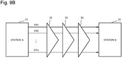
- Fig. 9B is a block diagram illustrating another example of the transmission system.
- a submarine cable system will be described as the transmission system.
- an optical transmission device 51 station A
- an optical transmission device 52 station B
- a laid fiber pair FP1, FP2, ..., FPm
- the transmission system is connected via a repeater 53, particularly a plurality of repeaters 53, inserted in the middle of the fiber pairs (FP1, FP2, ..., FPm) of the optical transmission line.
- all of the laid fiber pairs of the optical transmission line may not be operated from a time of starting, and an operation is started with a minimum configuration.
- the fiber pair FP1 of the optical transmission line in Fig. 9A and Fig. 9B is used, and the fiber pair FP2 and later of the optical transmission line are set as dark fibers in many cases.
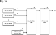
- Fig. 10 is a block diagram of a transmission-side transmission device of the optical transmission device according to the fourth example embodiment.
- Fig. 11A is a block diagram of the optical transmission device according to the fourth example embodiment in a state where only dummy light is being transmitted.
- Fig. 11B is a block diagram of the optical transmission device according to the fourth example embodiment that illustrates a redundant configuration in the state where only the dummy light is being transmitted.
- Fig. 12 is a block diagram of a reception-side transmission device of the optical transmission device according to the fourth example embodiment.
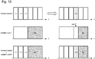
- Fig. 13 is a conceptual diagram illustrating ON/OFF control of the dummy light.
- Fig. 14 is a flowchart illustrating the ON/OFF control of the dummy light and the like.
- the transmission-side transmission device of the optical transmission device in Fig. 10 includes a plurality of transmitters la, 1b, ..., In, a multiplexing unit 2 (multiplexer (MUX)), a dummy light output unit 7, and a branching unit 8.
- the multiplexing unit 2 multiplexes main signals of the plurality of transmitters 1a, 1b, ..., In and the dummy light from the dummy light output unit 7, and sends the multiplexed main signals and the dummy light from the branching unit 8 to a fiber pair FP1 of the optical transmission line.
- the branching unit 8 may be achieved by a combination of an optical coupler and an optical switch.
- optical fiber monitoring can be performed by continuously sending an optical signal to the fiber pair FP1 of the optical transmission line by using the dummy light from the dummy light output unit 7 in a state without connecting the transmitter and a receiver as illustrated in Fig. 11A .
- the transmission-side transmission device of the optical transmission device in Fig. 11A includes the multiplexing unit 2, the dummy light output unit 7, and the branching unit 8.
- the transmission-side transmission device of the optical transmission device according to the present example embodiment can be a redundant configuration in which only the dummy light is being transmitted as illustrated in Fig. 11B .
- optical fiber monitoring can be performed by continuously sending an optical signal to the fiber pairs FP1 and FP2 of the optical transmission line by using the dummy light from the dummy light output unit 7 in a state without connecting the transmitter and the receiver as illustrated in Fig. 11B .
- the transmission-side transmission device of the optical transmission device in Fig. 11B includes the multiplexing unit 2, the dummy light output unit 7, and the branching unit 8.
- the branching unit 8 branches and sends the signal to the fiber pairs FP1 and FP2 of the optical transmission line, and sends the same dummy light signal to fiber pairs FP1 and FP2 of the optical transmission line.
- the branching unit 8 in Figs. 11A and 11B may be achieved by a combination of an optical coupler and an optical switch.
- the dummy light and the like sent to the fiber pair of the optical transmission line by the transmission-side transmission device can be monitored by the reception-side transmission device.
- the reception-side transmission device of the optical transmission device in Fig. 12 includes a plurality of receivers 21a, 21b, ..., 21n, a demultiplexer (DMUX) 22, a selector (SEL) 23, and an optical channel monitor (OCM) 24.
- DMUX demultiplexer
- SEL selector
- OCM optical channel monitor
- the optical signal received from fiber pair FP1 of the optical transmission line is selected by the selector 23, the selected optical signal is wavelength-demultiplexed by the demultiplexer 22, and the wavelength-demultiplexed optical signals are sent to a plurality of receivers 21a, 21b, ..., 21n. Further, in the OCM 24, it is possible to monitor the transmission line quality of the fiber pair FP1 of the optical transmission line.
- a transmitter is connected to the device configuration that sends only the dummy light to the optical fiber illustrated in Fig. 11A .
- a signal from the transmitter is input to a fiber band and an operation is started, light intensity and a wavelength are automatically determined and the dummy light is set to OFF appropriately.
- the transmitter is removed, the dummy light is set to ON.
- the transmitter to be connected to the transmission-side transmission device is a device capable of pre-emphasis control in such a way as to perform operation even when a signal with various wavelength bands is input.
- a plurality of transponders as a plurality of existing transmitters output a signal of a wavelength ⁇ 1, a signal of a wavelength ⁇ 2 on a longer wave side than the wavelength ⁇ 1, a signal of a wavelength ⁇ 3 on a longer wave side than the wavelength ⁇ 2, and a signal of a wavelength ⁇ 4 from an added transmitter.
- a center wavelength and a bandwidth of the signal are detected in the OCM 108 of the transmission-side transmission device in Fig. 5 or in the OCM 24 of the reception-side transmission device in Fig.
- the dummy light is set to OFF as the diagram illustrated in the middle of Fig. 13 .
- the dummy light is set to an adjustable light level in advance in such a way that an optical signal to noise ratio (OSNR) characteristic can be sufficiently secured.
- OSNR optical signal to noise ratio
- a power level of the dummy light is set as a reference value in advance by using the OCM 5 or the OCM 24, and the reference value is stored in the transmission-side transmission device or the reception-side transmission device (step S21).
- a center frequency and a bandwidth of a channel CH by the transmitter to be added to the transmission-side transmission device are set from a control terminal, and control is started (step S22).
- the dummy light overlapping with a main signal of the set wavelength is set to OFF (step S23). Setting the dummy light to OFF is automatically performed.
- the optical power of the wavelength by the added transmitter is monitored by the OCM 108 or the OCM 24, the optical power is adjusted by the multiplexing unit 2 in Fig. 10 or the demultiplexer 22 in Fig. 12 in such a way as to approach the reference value of the dummy light (step S24).
- a next added channel CH being set is adjusted. In this way, the control sequence is completed. It can be configured that, when fine adjustment is required after the completion of the control sequence, the adjustment can be performed manually from the control terminal.
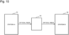
- an add/drop ratio in a submarine reconfigurable optical add-drop multiplexer (ROADM) device may be changed according to wavelength band control of dummy light.
- a submarine ROADM device 54 is provided on a transmission line connecting an optical transmission device 51 (station A) and an optical transmission device 52 (station B).
- an add/drop ratio in the submarine ROADM device 54 may be changed according to wavelength band control of dummy light.
- a transmission device transmits a control signal to the submarine ROADM device according to the wavelength band control of the dummy light.
Landscapes
- Engineering & Computer Science (AREA)
- Computer Networks & Wireless Communication (AREA)
- Signal Processing (AREA)
- Physics & Mathematics (AREA)
- Electromagnetism (AREA)
- Optical Communication System (AREA)
Applications Claiming Priority (2)
| Application Number | Priority Date | Filing Date | Title |
|---|---|---|---|
| JP2018014326 | 2018-01-31 | ||
| PCT/JP2019/001988 WO2019151067A1 (fr) | 2018-01-31 | 2019-01-23 | Dispositif de transmission optique, système de transmission, et procédé de commande pour système de transmission |
Publications (2)
| Publication Number | Publication Date |
|---|---|
| EP3748881A1 true EP3748881A1 (fr) | 2020-12-09 |
| EP3748881A4 EP3748881A4 (fr) | 2021-03-31 |
Family
ID=67479031
Family Applications (1)
| Application Number | Title | Priority Date | Filing Date |
|---|---|---|---|
| EP19747753.2A Withdrawn EP3748881A4 (fr) | 2018-01-31 | 2019-01-23 | Dispositif de transmission optique, système de transmission, et procédé de commande pour système de transmission |
Country Status (5)
| Country | Link |
|---|---|
| US (1) | US11115128B2 (fr) |
| EP (1) | EP3748881A4 (fr) |
| JP (1) | JP7036130B2 (fr) |
| CN (1) | CN111656712B (fr) |
| WO (1) | WO2019151067A1 (fr) |
Families Citing this family (10)
| Publication number | Priority date | Publication date | Assignee | Title |
|---|---|---|---|---|
| WO2020121716A1 (fr) * | 2018-12-12 | 2020-06-18 | 日本電気株式会社 | Dispositif de transmission optique, dispositif terminal, système de communication optique et procédé de communication optique |
| US10735837B1 (en) * | 2019-07-11 | 2020-08-04 | Ciena Corporation | Partial activation of a media channel on channel holder-based optical links |
| WO2021060124A1 (fr) * | 2019-09-27 | 2021-04-01 | 日本電気株式会社 | Système de communication optique, dispositif de communication optique, procédé de communication optique, et support d'informations |
| CN115244872B (zh) * | 2020-03-02 | 2024-06-04 | 日本电气株式会社 | 海底光通信系统和通信方法 |
| WO2021245847A1 (fr) * | 2020-06-03 | 2021-12-09 | 日本電気株式会社 | Dispositif de surveillance de signal optique et procédé de surveillance de signal optique |
| GB202012386D0 (en) * | 2020-08-10 | 2020-09-23 | Neptune Subsea Ip Ltd | Noise loading in an optical system |
| WO2022153349A1 (fr) | 2021-01-12 | 2022-07-21 | 日本電気株式会社 | Dispositif source de lumière, dispositif optique, procédé de génération de lumière de commande, et procédé de génération de lumière de surveillance |
| US12494860B2 (en) | 2021-03-25 | 2025-12-09 | Nec Corporation | Wavelength multiplexing device and wavelength multiplexing method |
| CN116112071A (zh) * | 2021-11-09 | 2023-05-12 | 中兴通讯股份有限公司 | 应用于otn网络的备用光通道性能检测方法及性能检测系统 |
| JP7815969B2 (ja) | 2022-04-26 | 2026-02-18 | 1Finity株式会社 | 光伝送システム及び受信装置 |
Family Cites Families (13)
| Publication number | Priority date | Publication date | Assignee | Title |
|---|---|---|---|---|
| TW508920B (en) * | 2000-06-01 | 2002-11-01 | Sumitomo Electric Industries | Optical transmission system |
| US6907195B2 (en) * | 2001-08-28 | 2005-06-14 | Dorsal Networks, Inc. | Terminals having sub-band substitute signal control in optical communication systems |
| JP2003244080A (ja) | 2002-02-14 | 2003-08-29 | Nippon Telegr & Teleph Corp <Ntt> | ダークファイバ監視試験方法および装置 |
| JP2005051598A (ja) * | 2003-07-30 | 2005-02-24 | Kddi Submarine Cable Systems Inc | 光伝送システムのアップグレード方法及び光送信装置 |
| JP4590944B2 (ja) | 2004-06-17 | 2010-12-01 | 日本電気株式会社 | 波長多重伝送システム及び光送信装置並びに波長多重伝送方法 |
| JP5076660B2 (ja) * | 2007-06-11 | 2012-11-21 | 日本電気株式会社 | 波長多重伝送装置、制御方法及び制御プログラム |
| JP5240673B2 (ja) * | 2009-03-19 | 2013-07-17 | 日本電気株式会社 | 光信号レベル調整システム及びこれにおける情報解析・制御信号生成装置並びに情報解析・制御信号生成方法 |
| US8971705B2 (en) | 2011-09-02 | 2015-03-03 | Ciena Corporation | Transient and switching event stabilization of fiber optic transport systems |
| JP6051994B2 (ja) * | 2013-03-25 | 2016-12-27 | 富士通株式会社 | 光伝送装置及びダミー光挿入方法 |
| JP6387965B2 (ja) | 2013-09-24 | 2018-09-12 | 日本電気株式会社 | 伝送装置、伝送システム、伝送方法及びプログラムが記憶された記憶媒体 |
| WO2016139933A1 (fr) | 2015-03-04 | 2016-09-09 | 日本電気株式会社 | Dispositif de surveillance de signal optique, appareil de transmission par multiplexage en longueur d'onde optique, et procédé de surveillance de signal optique |
| JP6350739B2 (ja) | 2015-03-18 | 2018-07-04 | 日本電気株式会社 | 光伝送システムとその解析方法、及び、端局装置、管理装置 |
| US11302919B2 (en) | 2016-07-20 | 2022-04-12 | Samsung Sdi Co., Ltd. | Nickel-based active material for lithium secondary battery, method of preparing the same, and lithium secondary battery including positive electrode including the nickel-based active material |
-
2019
- 2019-01-23 US US16/964,716 patent/US11115128B2/en active Active
- 2019-01-23 EP EP19747753.2A patent/EP3748881A4/fr not_active Withdrawn
- 2019-01-23 WO PCT/JP2019/001988 patent/WO2019151067A1/fr not_active Ceased
- 2019-01-23 CN CN201980009837.3A patent/CN111656712B/zh active Active
- 2019-01-23 JP JP2019569041A patent/JP7036130B2/ja active Active
Also Published As
| Publication number | Publication date |
|---|---|
| CN111656712B (zh) | 2022-10-25 |
| US20200358534A1 (en) | 2020-11-12 |
| WO2019151067A1 (fr) | 2019-08-08 |
| JP7036130B2 (ja) | 2022-03-15 |
| US11115128B2 (en) | 2021-09-07 |
| JPWO2019151067A1 (ja) | 2020-12-17 |
| EP3748881A4 (fr) | 2021-03-31 |
| CN111656712A (zh) | 2020-09-11 |
Similar Documents
| Publication | Publication Date | Title |
|---|---|---|
| US11115128B2 (en) | Optical transmission device, transmission system, and control method for transmission system | |
| EP2701316A1 (fr) | Dispositif de divergence avec fonction oadm et système de réseau optique à multiplexage par répartition en longueurs d'onde et procédé associé | |
| US11336386B2 (en) | Submarine branching apparatus, optical submarine cable system, and optical communication method | |
| US6577652B1 (en) | Optical add-drop multiplexer of WDM optical signals | |
| US11251895B2 (en) | Seabed branching device, optical seabed cable system, and optical communication method | |
| US9467244B2 (en) | Transmission apparatus and transmission system | |
| US20240364443A1 (en) | Optical transmission device and optical communication system | |
| US7206510B2 (en) | Ring network using multi-wavelength generator | |
| US11949448B2 (en) | Submarine optical communication system and communication method | |
| US20060198636A1 (en) | Wavelength grid for DWDM | |
| EP2852081A1 (fr) | Réseau optique en anneau | |
| US11558122B2 (en) | Optical transmission apparatus, terminal station apparatus, optical communication system, and optical communication method | |
| US12463725B2 (en) | Optical add/drop multiplexer and optical transmission method | |
| US11336375B2 (en) | Optical transmission apparatus, optical communication system, and optical signal transmission method | |
| JP7168064B2 (ja) | 光合分波装置、光海底ケーブルシステム、光合分波方法及びプログラム | |
| US20210036797A1 (en) | Optical transmission apparatus, optical communication system and optical communication method | |
| JP7428234B2 (ja) | スペクトラム監視装置、海底機器及び光通信システム | |
| EP1529414B1 (fr) | Interconnexions dans des reseaux de telecommunication |
Legal Events
| Date | Code | Title | Description |
|---|---|---|---|
| STAA | Information on the status of an ep patent application or granted ep patent |
Free format text: STATUS: THE INTERNATIONAL PUBLICATION HAS BEEN MADE |
|
| PUAI | Public reference made under article 153(3) epc to a published international application that has entered the european phase |
Free format text: ORIGINAL CODE: 0009012 |
|
| STAA | Information on the status of an ep patent application or granted ep patent |
Free format text: STATUS: REQUEST FOR EXAMINATION WAS MADE |
|
| 17P | Request for examination filed |
Effective date: 20200823 |
|
| AK | Designated contracting states |
Kind code of ref document: A1 Designated state(s): AL AT BE BG CH CY CZ DE DK EE ES FI FR GB GR HR HU IE IS IT LI LT LU LV MC MK MT NL NO PL PT RO RS SE SI SK SM TR |
|
| AX | Request for extension of the european patent |
Extension state: BA ME |
|
| A4 | Supplementary search report drawn up and despatched |
Effective date: 20210301 |
|
| RIC1 | Information provided on ipc code assigned before grant |
Ipc: H04B 10/564 20130101ALI20210223BHEP Ipc: H04J 14/02 20060101AFI20210223BHEP Ipc: H04B 10/079 20130101ALI20210223BHEP Ipc: H04B 10/572 20130101ALI20210223BHEP |
|
| DAV | Request for validation of the european patent (deleted) | ||
| DAX | Request for extension of the european patent (deleted) | ||
| STAA | Information on the status of an ep patent application or granted ep patent |
Free format text: STATUS: EXAMINATION IS IN PROGRESS |
|
| 17Q | First examination report despatched |
Effective date: 20231206 |
|
| STAA | Information on the status of an ep patent application or granted ep patent |
Free format text: STATUS: THE APPLICATION HAS BEEN WITHDRAWN |
|
| 18W | Application withdrawn |
Effective date: 20240209 |