EP3749403B1 - Ensemble respiratoire nasal - Google Patents
Ensemble respiratoire nasal Download PDFInfo
- Publication number
- EP3749403B1 EP3749403B1 EP19750901.1A EP19750901A EP3749403B1 EP 3749403 B1 EP3749403 B1 EP 3749403B1 EP 19750901 A EP19750901 A EP 19750901A EP 3749403 B1 EP3749403 B1 EP 3749403B1
- Authority
- EP
- European Patent Office
- Prior art keywords
- assembly
- patient
- post
- tubing
- fluid
- Prior art date
- Legal status (The legal status is an assumption and is not a legal conclusion. Google has not performed a legal analysis and makes no representation as to the accuracy of the status listed.)
- Active
Links
Images






Classifications
-
- A—HUMAN NECESSITIES
- A61—MEDICAL OR VETERINARY SCIENCE; HYGIENE
- A61M—DEVICES FOR INTRODUCING MEDIA INTO, OR ONTO, THE BODY; DEVICES FOR TRANSDUCING BODY MEDIA OR FOR TAKING MEDIA FROM THE BODY; DEVICES FOR PRODUCING OR ENDING SLEEP OR STUPOR
- A61M16/00—Devices for influencing the respiratory system of patients by gas treatment, e.g. ventilators; Tracheal tubes
- A61M16/06—Respiratory or anaesthetic masks
- A61M16/0666—Nasal cannulas or tubing
-
- A—HUMAN NECESSITIES
- A61—MEDICAL OR VETERINARY SCIENCE; HYGIENE
- A61L—METHODS OR APPARATUS FOR STERILISING MATERIALS OR OBJECTS IN GENERAL; DISINFECTION, STERILISATION OR DEODORISATION OF AIR; CHEMICAL ASPECTS OF BANDAGES, DRESSINGS, ABSORBENT PADS OR SURGICAL ARTICLES; MATERIALS FOR BANDAGES, DRESSINGS, ABSORBENT PADS OR SURGICAL ARTICLES
- A61L2/00—Disinfection or sterilisation of materials or objects, in general; Accessories therefor
- A61L2/02—Disinfection or sterilisation of materials or objects, in general; Accessories therefor using physical processes
- A61L2/08—Radiation
- A61L2/10—Ultraviolet [UV] radiation
-
- A—HUMAN NECESSITIES
- A61—MEDICAL OR VETERINARY SCIENCE; HYGIENE
- A61L—METHODS OR APPARATUS FOR STERILISING MATERIALS OR OBJECTS IN GENERAL; DISINFECTION, STERILISATION OR DEODORISATION OF AIR; CHEMICAL ASPECTS OF BANDAGES, DRESSINGS, ABSORBENT PADS OR SURGICAL ARTICLES; MATERIALS FOR BANDAGES, DRESSINGS, ABSORBENT PADS OR SURGICAL ARTICLES
- A61L2/00—Disinfection or sterilisation of materials or objects, in general; Accessories therefor
- A61L2/16—Disinfection or sterilisation of materials or objects, in general; Accessories therefor using chemical substances
- A61L2/20—Gaseous substances, e.g. vapours
- A61L2/202—Ozone
-
- A—HUMAN NECESSITIES
- A61—MEDICAL OR VETERINARY SCIENCE; HYGIENE
- A61M—DEVICES FOR INTRODUCING MEDIA INTO, OR ONTO, THE BODY; DEVICES FOR TRANSDUCING BODY MEDIA OR FOR TAKING MEDIA FROM THE BODY; DEVICES FOR PRODUCING OR ENDING SLEEP OR STUPOR
- A61M16/00—Devices for influencing the respiratory system of patients by gas treatment, e.g. ventilators; Tracheal tubes
- A61M16/04—Tracheal tubes
- A61M16/0488—Mouthpieces; Means for guiding, securing or introducing the tubes
- A61M16/049—Mouthpieces
-
- A—HUMAN NECESSITIES
- A61—MEDICAL OR VETERINARY SCIENCE; HYGIENE
- A61M—DEVICES FOR INTRODUCING MEDIA INTO, OR ONTO, THE BODY; DEVICES FOR TRANSDUCING BODY MEDIA OR FOR TAKING MEDIA FROM THE BODY; DEVICES FOR PRODUCING OR ENDING SLEEP OR STUPOR
- A61M16/00—Devices for influencing the respiratory system of patients by gas treatment, e.g. ventilators; Tracheal tubes
- A61M16/06—Respiratory or anaesthetic masks
- A61M16/0605—Means for improving the adaptation of the mask to the patient
- A61M16/0616—Means for improving the adaptation of the mask to the patient with face sealing means comprising a flap or membrane projecting inwards, such that sealing increases with increasing inhalation gas pressure
- A61M16/0622—Means for improving the adaptation of the mask to the patient with face sealing means comprising a flap or membrane projecting inwards, such that sealing increases with increasing inhalation gas pressure having an underlying cushion
-
- A—HUMAN NECESSITIES
- A61—MEDICAL OR VETERINARY SCIENCE; HYGIENE
- A61M—DEVICES FOR INTRODUCING MEDIA INTO, OR ONTO, THE BODY; DEVICES FOR TRANSDUCING BODY MEDIA OR FOR TAKING MEDIA FROM THE BODY; DEVICES FOR PRODUCING OR ENDING SLEEP OR STUPOR
- A61M16/00—Devices for influencing the respiratory system of patients by gas treatment, e.g. ventilators; Tracheal tubes
- A61M16/06—Respiratory or anaesthetic masks
- A61M16/0683—Holding devices therefor
- A61M16/0688—Holding devices therefor by means of an adhesive
-
- A—HUMAN NECESSITIES
- A61—MEDICAL OR VETERINARY SCIENCE; HYGIENE
- A61M—DEVICES FOR INTRODUCING MEDIA INTO, OR ONTO, THE BODY; DEVICES FOR TRANSDUCING BODY MEDIA OR FOR TAKING MEDIA FROM THE BODY; DEVICES FOR PRODUCING OR ENDING SLEEP OR STUPOR
- A61M16/00—Devices for influencing the respiratory system of patients by gas treatment, e.g. ventilators; Tracheal tubes
- A61M16/08—Bellows; Connecting tubes ; Water traps; Patient circuits
- A61M16/0816—Joints or connectors
-
- A—HUMAN NECESSITIES
- A61—MEDICAL OR VETERINARY SCIENCE; HYGIENE
- A61M—DEVICES FOR INTRODUCING MEDIA INTO, OR ONTO, THE BODY; DEVICES FOR TRANSDUCING BODY MEDIA OR FOR TAKING MEDIA FROM THE BODY; DEVICES FOR PRODUCING OR ENDING SLEEP OR STUPOR
- A61M16/00—Devices for influencing the respiratory system of patients by gas treatment, e.g. ventilators; Tracheal tubes
- A61M16/10—Preparation of respiratory gases or vapours
- A61M16/1045—Devices for humidifying or heating the inspired gas by using recovered moisture or heat from the expired gas
-
- A—HUMAN NECESSITIES
- A61—MEDICAL OR VETERINARY SCIENCE; HYGIENE
- A61L—METHODS OR APPARATUS FOR STERILISING MATERIALS OR OBJECTS IN GENERAL; DISINFECTION, STERILISATION OR DEODORISATION OF AIR; CHEMICAL ASPECTS OF BANDAGES, DRESSINGS, ABSORBENT PADS OR SURGICAL ARTICLES; MATERIALS FOR BANDAGES, DRESSINGS, ABSORBENT PADS OR SURGICAL ARTICLES
- A61L2103/00—Materials or objects being the target of disinfection or sterilisation
- A61L2103/15—Laboratory, medical or dentistry appliances, e.g. catheters or sharps
-
- A—HUMAN NECESSITIES
- A61—MEDICAL OR VETERINARY SCIENCE; HYGIENE
- A61L—METHODS OR APPARATUS FOR STERILISING MATERIALS OR OBJECTS IN GENERAL; DISINFECTION, STERILISATION OR DEODORISATION OF AIR; CHEMICAL ASPECTS OF BANDAGES, DRESSINGS, ABSORBENT PADS OR SURGICAL ARTICLES; MATERIALS FOR BANDAGES, DRESSINGS, ABSORBENT PADS OR SURGICAL ARTICLES
- A61L2202/00—Aspects relating to methods or apparatus for disinfecting or sterilising materials or objects
- A61L2202/10—Apparatus features
- A61L2202/12—Apparatus for isolating biocidal substances from the environment
- A61L2202/122—Chambers for sterilisation
-
- A—HUMAN NECESSITIES
- A61—MEDICAL OR VETERINARY SCIENCE; HYGIENE
- A61M—DEVICES FOR INTRODUCING MEDIA INTO, OR ONTO, THE BODY; DEVICES FOR TRANSDUCING BODY MEDIA OR FOR TAKING MEDIA FROM THE BODY; DEVICES FOR PRODUCING OR ENDING SLEEP OR STUPOR
- A61M16/00—Devices for influencing the respiratory system of patients by gas treatment, e.g. ventilators; Tracheal tubes
- A61M16/08—Bellows; Connecting tubes ; Water traps; Patient circuits
- A61M16/0816—Joints or connectors
- A61M16/0825—Joints or connectors with ball-sockets
-
- A—HUMAN NECESSITIES
- A61—MEDICAL OR VETERINARY SCIENCE; HYGIENE
- A61M—DEVICES FOR INTRODUCING MEDIA INTO, OR ONTO, THE BODY; DEVICES FOR TRANSDUCING BODY MEDIA OR FOR TAKING MEDIA FROM THE BODY; DEVICES FOR PRODUCING OR ENDING SLEEP OR STUPOR
- A61M16/00—Devices for influencing the respiratory system of patients by gas treatment, e.g. ventilators; Tracheal tubes
- A61M16/10—Preparation of respiratory gases or vapours
- A61M16/12—Preparation of respiratory gases or vapours by mixing different gases
-
- A—HUMAN NECESSITIES
- A61—MEDICAL OR VETERINARY SCIENCE; HYGIENE
- A61M—DEVICES FOR INTRODUCING MEDIA INTO, OR ONTO, THE BODY; DEVICES FOR TRANSDUCING BODY MEDIA OR FOR TAKING MEDIA FROM THE BODY; DEVICES FOR PRODUCING OR ENDING SLEEP OR STUPOR
- A61M16/00—Devices for influencing the respiratory system of patients by gas treatment, e.g. ventilators; Tracheal tubes
- A61M16/10—Preparation of respiratory gases or vapours
- A61M16/14—Preparation of respiratory gases or vapours by mixing different fluids, one of them being in a liquid phase
- A61M16/16—Devices to humidify the respiration air
-
- A—HUMAN NECESSITIES
- A61—MEDICAL OR VETERINARY SCIENCE; HYGIENE
- A61M—DEVICES FOR INTRODUCING MEDIA INTO, OR ONTO, THE BODY; DEVICES FOR TRANSDUCING BODY MEDIA OR FOR TAKING MEDIA FROM THE BODY; DEVICES FOR PRODUCING OR ENDING SLEEP OR STUPOR
- A61M2205/00—General characteristics of the apparatus
- A61M2205/02—General characteristics of the apparatus characterised by a particular materials
Definitions
- the presently disclosed subject matter relates to a respiratory assembly, and to methods of making, using and sanitizing the assembly.
- Facial masks and nasal cannula are commonly used for treating patients with sleeping and/or breathing disorders. Particularly, high flow delivery of respirator gas can be delivered using nasal cannula and/or facial masks. Further, continuous positive airway pressure (CPAP) masks can deliver a treatment fluid (such as ambient air or oxygen-enriched air) to a patient under a predetermined or desired pressure setting.
- CPAP continuous positive airway pressure
- prior art masks and cannula are typically bulky, making them less aesthetically and ergonomically pleasing. Further, conventional masks and cannula must provide sealable engagement with the patient's skin, leaving unsightly wear marks that require significant amounts of time to dissipate.
- depressions or marks can be the result of the masks enveloping the mouth and/or the nostril, as well as the straps or connections that typically positioned about the patient's head.
- the patient's ability to move their head during sleep is affected. Particularly, when a patient lies on his side during sleep, the patient's pillow can contact and dislodge the mask, thereby evacuating the pressure in the mask assembly. As a result, the patient wakes up and/or does not receive treatment gases under the ideal pressure.
- US20050199242A1 (hereinafter referred to as "D1") teaches patient interface devices that provide a stable platform supporting a sealing assembly for coupling a flow of gas with an airway of a patient, are relatively small to minimize the amount of material supported on the patient's face and head, and yet provide a high degree of adjustability, so that the patient interface device fits comfortably on a wide variety of differently sized and shaped patients as noted in paragraph [0003] of D1.
- patient interface devices are typically bulky masks which can block vision and are worn for extended period of time which can cause discomfort, particularly when supported and strapped with enough force so an adequate seal is maintained and when not adjustable for different sized and shaped patients.
- D1 attempts to solve the problems by providing various embodiments of a patient interface device which all involve a support member, sealing assembly, and a pair of patient contacting members to secure the device on the face of the patient. Similar to the embodiment of the patient interface device described in paragraph [0069] of D1, all embodiments of the patient interface device include or are to be utilized with some version of a headgear attachment assembly. Indeed, as discussed in paragraph [0085] of D1, there are a variety of alternative embodiments for headgear attachment assemblies suitable for use with their patient interface device, such as those illustrated in Figures 13-24. Accordingly, all embodiments disclosed in D1 need a headgear to maintain engagement of the sealing assembly.
- EP3246064A1 (hereinafter referred to as "D2") teaches a nasal gas-delivery system comprising two prongs that are inserted into the patient's nostrils for delivering a respiratory gas to a patient in need thereof, and sealing collars or flanges which allows improving the sealing between nasal gas-delivery system and the nose of a patient, especially useable in the frame of a nasal High Flow therapy (NHFT).
- NHFT is limited and has drawbacks due to the lack of a sealed interface.
- D2 attempts to solve the issues through a nasal gas-delivery system connected to a nose of a patient with flanges contacting a nose to create a gas-tight connection therebetween.
- the flanges are part of a nasal sub-system which must be maintained in position relative to the nostrils of a patient by straps, headgear, or similar fixing system. Accordingly, to maintain a gas-tight connection and solve the issues associated with NHFT, the embodiments of D2 must be maintained in position through a strap or headgear assembly.
- WO2005076874A2 (hereinafter referred to as "D3") teaches a patient interface assembly for use in a pressure support system to deliver gas to a patient, where the patient interface assembly is supported under at least a portion of the patient's mandible.
- non-invasive ventilation and pressure support therapies involve maintaining patient interface device on the face of a patient, through a headgear using straps, for an extended period which can cause discomfort, shifting, disruptions in the seal, claustrophobic effects, and avoidance of wearing the patient interface device, particularly while sleeping.
- D3 attempts to solve the issues through the use of a chin support coupled to the patient interface. All embodiments of the patient interface of D3, though, involve some assemblage of headgear and straps, as paragraphs [04] - [05] provide that the embodiments of D3 provide improvements and benefits to patient interface devices maintained in place by straps and headgear.
- US20090095303A1 (hereinafter referred to as "D4") teaches a nasal prong for a ventilation interface which includes a guide on the nasal prong, such as that described in [0054] of D4 to assist with positioning and retaining a nasal pillow.
- these nasal prongs are used with ventilation interfaces/respiration assist masks.
- an exemplary version of the ventilation interface/respiration assist mask is shown in Figure 6 with receiving holes to hold the nasal pillows in a position that to allow an airtight seal to be formed between the nasal pillows and the nares of a user wearing the mask.
- D4 portions of the nasal prongs can deform and/or compress when pressed against a user's nasal openings to form a seal. Accordingly, the nasal prongs of D4 require being pushed against portions of a nose to form a seal, which implies some strap or headgear, such as that disclosed in Figure 6 .
- CPAP pathogens can build up in the CPAP assembly.
- CPAP pathogens can build up in the CPAP assembly.
- a variety of health issues can arise, including pneumonia, bronchitis, infections, nasal passage irritation, and the like.
- Disinfecting wipes are commonly used to clean and deodorize CPAP masks and accessories.
- the wipes have been found to transfer bacteria and spores onto multiple surfaces.
- soap and water are used to clean CPAP equipment. Unfortunately, this method is time consuming and inconvenient, since the user must take the CPAP equipment apart and wash each piece with soapy water.
- a nasal respiratory assembly comprising flexible tubing connected to a fluid source, wherein the flexible tubing comprises a pair of receptacles through which the fluid is dispensed; a pair of posts, and a connector with a central opening sized and shaped to cooperate with one of the receptacles.
- Each post comprises a flange sized and shaped to fit over the nostril of a patient; a main body comprising a passageway configured therein.
- the flexible tubing has an inner diameter of about 2-4 mm.
- the fluid source is selected from a high flow generator, a continuous positive airway pressure (CPAP) machine, a fluid tank, or a humidifier.
- CPAP continuous positive airway pressure
- the fluid is a gas with a medication.
- the flange is angled.
- the angle is between about 0 degrees and about 45 degrees.
- the connector portion of the posts includes a ridge.
- the receptacles each comprise a socket.
- the socket comprises: a collar positioned at a first end; an adaptor positioned at a second end; a passageway extending from the first to the second ends; and a cavity positioned at the first end, sized and shaped to releasably house the connector and at least a portion of the post body therein.
- the collar includes one or more releases that can be pivoted to maintain or release the post within the cavity.
- an oral assembly comprising an internal plate curved arcuately to fit in between the teeth and lips of a patient; an external plate curved arcuately to be positioned directly adjacent to an external surface of the mouth of the patient; a passageway extending through the internal plate and the external plate, wherein the passageway is releasably connected to a tubing that is connected to a fluid source; and a gasket in fluid connection to the passageway, the gasket comprising an aperture that connects to the tubing connected to the fluid source.
- the internal plate is molded with an impression of the patient's top teeth, bottom teeth, or both the top and bottom teeth.
- the passageway extends through the approximate center portion of the internal plate and the external plate.
- the assembly lacks straps, masks, or both.
- the internal plate comprises an upper segment and a lower segment connected via a hinge to allow movement of each segment in relation to the other.
- the upper segment is molded to correspond to the shape of the upper teeth of the patient
- the lower segment is molded to correspond to the shape of the lower teeth of the patient, or both.
- a cushion is positioned between the external plate and the external surface of the patient's mouth.
- the cushion is constructed from foam or silicone material.
- the cushion has a central opening passing therethrough.
- the gasket is positioned adjacent to the exterior plate, external to the patient's mouth.
- the gasket comprises a swivel ring that allows connection to a fluid source, wherein the swivel ring allows the fluid source to swivel when connected.
- the swivel ring comprises two branches, each branch including a socket positioned at a distal end.
- a respiratory assembly comprising a nasal assembly comprising flexible tubing including a pair of receptacles through which a fluid is dispensed; a pair of posts, each post comprising a flange sized and shaped to fit over the nostril of a patient; a main body comprising a passageway configured therein; a connector with a central opening sized and shaped to cooperate with one of the receptacles; and an oral assembly.
- the oral assembly comprises an internal plate curved arcuately to fit in between the teeth and lips of a patient; an external plate curved arcuately to be positioned directly adjacent to an external surface of the mouth of the patient; a passageway extending through the internal plate and the external plate, wherein the passageway is releasably connected to a gasket that is connected to a fluid source, the gasket in fluid connection to the passageway, wherein the gasket is in fluid connection to the receptacles of the flexible tubing of the nasal assembly.
- the method comprises attaching a nasal assembly to the nares of a patient, the nasal assembly comprising: flexible tubing connected to a fluid source, wherein the flexible tubing comprises a pair of receptacles through which the fluid is dispensed; a pair of posts, each post comprising: a flange sized and shaped to fit over the nostril of a patient; a main body comprising a passageway configured therein; a connector with a central opening sized and shaped to cooperate with one of the receptacles; and initiating flow of the fluid source, wherein fluid flows from the fluid source to the flexible tubing to the receptacles to the passageways of the posts into the nasal passages of the patient.
- the method comprises: attaching an oral assembly to the mouth of a patient, the oral assembly comprising: an internal plate curved arcuately to fit in between the teeth and lips of a patient; an external plate curved arcuately to be positioned directly adjacent to an external surface of the mouth of the patient; a passageway extending through the internal plate and the external plate, wherein the passageway is releasably connected to tubing that is connected to a fluid source; and a gasket in fluid connection to the passageway, the gasket comprising an aperture that connects to a tubing of a fluid source; connecting the gasket to a fluid source; initiating flow of the fluid source, wherein fluid flows from the fluid source to the gasket to the passageway to the oral respiratory passages of the patient.
- the method comprises: attaching an oral assembly to the mouth of a patient, the oral assembly comprising: an internal plate curved arcuately to fit in between the teeth and lips of a patient; an external plate curved arcuately to be positioned directly adjacent to an external surface of the mouth of the patient; a passageway extending through the internal plate and the external plate, wherein the passageway is releasably connected to tubing that is connected to a fluid source; and a gasket in fluid connection to the passageway, the gasket comprising an aperture that connects to a tubing of a fluid source; and attaching a nasal assembly to the nares of a patient.
- the nasal assembly comprises: flexible tubing in fluid connection to the gasket, the flexible tubing including a pair of receptacles through which the fluid can flow through; a pair of posts, each post comprising: a flange sized and shaped to fit over the nostril of a patient; a main body comprising a passageway configured therein; a connector with a central opening sized and shaped to cooperate with one of the receptacles; and connecting the gasket to the fluid source; and initiating flow of the fluid source, wherein fluid flows from the fluid source to the gasket and then into two gasket branches, wherein the first branch comprises the passageway to the oral respiratory passages of the patient and the second branch is in fluid connection to the flexible tubing of the nasal assembly of the patient.
- the assembly comprises: flexible tubing connected to a fluid source, wherein the flexible tubing comprises a pair of receptacles through which the fluid is dispensed; a pair of posts, each post comprising: a flange sized and shaped to fit over the nostril of a patient; a main body comprising a passageway configured therein; a connector with a central opening sized and shaped to cooperate with one of the receptacles; and an enclosure.
- the enclosure comprises: a pair of opposing sidewalls, a front wall, a rear wall, a bottom wall, and a top lid that define an interior; a generator positioned within the interior, wherein the generator is capable of generating activated oxygen, UV light, or both; an aperture configured in a sidewall of the enclosure, sized and shaped to house the flexible tubing.
- the lid is attached to the rear wall through one or more mechanical elements.
- the mechanical element comprises a hinge.
- the aperture is positioned adjacent to the lid.
- the UV light has a wavelength of about 100-280 nanometers.
- the generator produces activated oxygen at a concentration of about 10-500 parts per million.
- the flexible tubing has an inner diameter of about 2-4 mm.
- the enclosure is attached to the fluid source.
- the generator comprises a built-in timer that controls the release of activated oxygen, UV light, or both.
- the method comprises: depositing a pair of receptacles and a portion of flexible tubing of a respiratory assembly into an interior of an enclosure.
- the respiratory assembly comprises: flexible tubing connected to a continuous positive airway pressure device, wherein the flexible tubing comprises a pair of receptacles through which fluid is dispensed; a pair of posts, each post comprising: a flange sized and shaped to fit over the nostril of a patient; a main body comprising a passageway configured therein; and. a connector with a central opening sized and shaped to cooperate with one of the receptacles.
- the enclosure comprises: a pair of opposing sidewalls, a front wall, a rear wall, a bottom wall, and a top lid that define an interior; a generator positioned within the interior, wherein the generator is capable of generating activated oxygen, UV light, or both; an aperture configured in a sidewall of the enclosure, sized and shaped to house the portion of the flexible tubing; and initiating the production of activated oxygen, UV light, or both within the interior of the enclosure.
- the generated activated oxygen, UV light, or both travels from the interior of the enclosure, through the flexible tubing to a continuous positive airway pressure device in fluid communication to the flexible tubing, whereby the respiratory assembly is sanitized.
- the lid is attached to the rear wall through one or more mechanical elements.
- the mechanical element comprises a hinge.
- the aperture is positioned adjacent to the lid.
- the UV light has a wavelength of about 100-280 nanometers.
- the generator produces activated oxygen at a concentration of about 10-500 parts per million.
- the flexible tubing has an inner diameter of about 2-4 mm.
- the enclosure is attached to the continuous positive airway pressure device.
- the generator comprises a built-in timer that controls the release of activated oxygen, UV light, or both.
- the enclosure is permanently or removably attached to the continuous positive airway pressure device.
- sanitizing of the respiratory assembly commences automatically when the top lid is closed.
- the top lid automatically unlocks after sanitizing of the respiratory assembly is completed.
- the continuous positive airway pressure device is connected to the respiratory assembly when the sanitizing of the respiratory assembly is underway.
- the enclosure further comprises an indicator light that illuminates when the sanitizing process is underway.
- the term "about”, when referring to a value or to an amount of mass, weight, time, volume, concentration, and/or percentage can encompass variations of, in some embodiments +/-20%, in some embodiments +/-10%, in some embodiments +/-5%, in some embodiments +/-1%, in some embodiments +/-0.5%, and in some embodiments +/-0.1%, from the specified amount, as such variations are appropriate in the disclosed packages and methods.
- nasal assembly 5 comprises flexible tubing 10 that includes at least one receptacle 15 for delivering treatment gases to the nasal cavity of a patient.
- the nasal assembly further includes posts 20 that are configured to engage the nares ( i.e., nostrils) of the patient.
- the receptacles are configured as prongs that are inserted into posts 20.
- Tubing 10 has an inlet connected to a fluid source (not shown) that provides the respiratory gas.
- the fluid source can be a high flow generator, a continuous positive airway pressure (CPAP) machine, a fluid tank, a humidifier, or any other fluid source known or used in the art.
- CPAP continuous positive airway pressure
- fluid refers to any gas, mixture of gases, or gas with medication (such as an aerosol medication) suitable for delivery to the airway of a human.
- Tubing 10 can include any known flexible tubing.
- tubing refers to any conduit, a delivery conduit, a tube, pipe, passage, or channel through which fluid flows.
- flexible refers to any tubing that is able to flex or bend and that is compliant and will readily conform to the general shape and contours of the human body.
- tubing 10 can be constructed from medical grade materials, such as (but not limited to) polyurethane, polyvinyl chloride, polyamide, polyester, polyolefin, silicone, fluoropolymer, and combinations or copolymers thereof.
- the tubing is flexible, resilient, and hollow.
- the tubing can have an inner diameter of between about 2-4 mm, although tubing with larger or smaller diameters can be used.
- the inner diameter of the tubing can be increased or decreased to adjust for a particular wearer's preferences and/or needs.
- tubing 10 can be hooked over the ears of a patient and can brought up under the chin during use.
- tubing 10 can include a short pair of radially-directed receptacles 15 configured as nasal prongs that extend into the nostrils of the wearer and are removably engageable with posts 20.
- the receptacles are parallel or about parallel to each other.
- the nasal receptacles are in fluid communication with the interior of the tubing, such that respiratory fluid flows from exit end 16 of each receptacle.
- each nasal receptacle comprises a unique pathway for conveying fluid from the inner tubing to the nasal passage of the patient.
- the receptacles can have various shapes, such as a circular, oval or rectangular in cross-section.
- nasal assembly 5 includes a pair of posts 20.
- receptacles 15 cooperate with posts 20 that are configured to engage the nostrils of the patient.
- the posts can be configured for providing a flush, sealable engagement with the patient's nares.
- post 20 comprises flange 25 that directly contacts the exterior of a patient's nostril or the skin surrounding the patient's nostril, body 30, and connector 35.
- the interior of post 20 includes channel 36 passing through the entire length thereof to allow fluid flow to the nasal cavity of the patient.
- Interior channel 36 is sized and shaped to allow for insertion of a receptacle during use.
- Flange 25 is configured about a first end of the post.
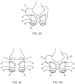
- the flange engages with one or more flexible adhesive sheets 40 to provide sealable engagement with the patient's nostrils, as shown in Fig. 3d .
- Sheet 40 can be constructed from any known material, including (but not limited to) woven fabric, plastic, and/or latex.
- sheet 40 can be constructed from PVC, polyethylene, polyurethane, latex, or combinations thereof.
- sheet 40 can be a foam medical tape, a surgical tape, and/or a hypoallergenic tape.
- the patient contacting surface of sheet 40 can include adhesive 41.
- the adhesive can be any medically-safe adhesive known or used in the art.
- the adhesive can be selected from one or more acrylates (such as methacrylate, alkyl acrylate, or epoxy diacrylate), acrylic acids, polyvinyl chloride, alkyl esters, or combinations thereof.
- the adhesive is a pressure-sensitive adhesive such that the sheet can be adhered and removed from the patient's skin as desired.
- the adhesive can be selected to show mild or no irritation to the skin when used daily.
- the adhesive tape can be configured as a hydrocolloid tape and/or can include a polyurethane reactive layer that adheres more to the nostril as the patient's body temperature warms up the adhesive.
- adhesive 41 can be directly applied to the patient's nostril or the nasal engaging portion to provide a removeable connection (e.g., no sheet is used).
- flange 25 can be angled in relation to body 30 to allow for enhanced positioning on the patient's nostrils.
- the angle can be between about 0-45 degrees, such as about 5, 10, 15, 20, 25, 30, 35, 40, or 45 degrees.
- the angle can be created by having a portion of the post body bulge outwards at an angle.
- post body 30 can remain substantially cylindrical, having a top portion cut at an angle.
- Post body 30 houses channel 36 within its interior to allow the flow of fluid to the nasal cavity of the patient.
- body 30 can have a circular, oval or square cross-sectional shape.
- the shape of body 30 is not limited and can be configured in any desired shape.
- channel 36 can have any desired cross-sectional shape, such as square, triangular, circular, oval, and the like.
- post 20 further includes connector 35 configured on a second post end for engaging receptacle 15 and/or a socket.
- connector 35 can comprise a tapered ridge, as illustrated in Figs. 3a-3d .
- the shape of the connector is not limited, and can be constructed to enable insertion of receptacle 15 and/or to enable connection with one or more sockets, as set forth in more detail herein below.
- connector 35 can be configured to selectively engage a receiving portion on a receptacle. The engagement of the connector with the receptacle can be achieved using a number of different structural configurations.
- connector 35 can be a circumferentially extending portion for selectively engaging a respective recess-receiving portion on a receptacle.
- the connector can be a ball joint and the receiving portion can be a tube socket, as set forth in more detail herein below.
- post 20 can include one or more vents in communication with channel 36 to ensure that the patient's ability to breathe is not hampered, and to ensure excess fluid has an outlet.
- the vents can be sized and shaped in any desired configuration and can be positioned proximal to any of the regions where fluid flow occurs.
- the vents can be positioned on the flange, body, and/or connector of the post.
- the vents can vary in size and location such that manipulation of all exhaled fluids (e.g., CO2) is controlled and titratable to alter the flow rate to a desired setting.
- the vents can include polymeric fibers, membranes, and/or webs with an extremely small thickness (e.g., from nanoscale to microscale).
- Post 20 can be constructed from any desired material.
- the post can be constructed from rubber, silicone polymers, acrylate polymers, or combinations thereof. It should be appreciated that the materials used to construct post are not limited to the materials cited herein above.
- Figs. 4a-4d illustrate one method of using post 20.
- a post can be attached to the exterior portion of each patient nostril 3 by affixing post flange 25 directly to the skin surrounding the nostril.
- post channel 36 is positioned in line with the nostril opening.
- sheet 40 comprising adhesive 41 can be used can be used to attach the flange to the nostril, as illustrated in Figs. 4a and 4b .
- the adhesive side of the sheet can be used to adhere flange 25 to the skin of the patient.
- adhesive 41 can be directly applied to the patient's skin (e.g., the area surrounding the nostril) or to the flange without the use of sheet 40.
- the post can be configured for providing a flush, sealable engagement with the patient's nostril.
- receptacle 15 of tubing 10 can be translated towards channel 36 at the second end of the post.
- open exit ends 16 (gas-flow end) of the receptacle is inserted at least partially into channel 36. Fluid flows from the tubing, through the interior of the receptacle, exits the receptacle via exit end 16 and flows to channel 36 and into the patient's nasal passages.
- tubing receptacles 15 can be configured as sockets 50 that releasably connect with posts 20.
- socket 50 can include one or more releases for engaging and disengaging the post from the socket.
- the release can include any of the wide variety of connection mechanisms known or used in the art, including (but not limited to) snap fit, screw fit, friction fit, magnetic attraction, and the like.
- the release can be configured as one or more arms 55 that extend from collar end 65 of the socket. The arms can be constructed at an angle to provide leverage when pivoting the arm, thereby enabling socket collar 65 to be deformed away from the post positioned in recess 70 for easy release.
- the socket further includes adaptor 67 positioned at the end distal from collar end 65.
- Adaptor 67 includes channel 90 that connects with cavity 70 to allow the flow of fluid from the tubing to reach the post.
- the adaptor can be constructed in any desired shape to allow connection with tubing 10. In such embodiments, the outer diameter of adaptor 67 is greater than the inner diameter of tubing 10. In this way, the adaptor is held within the tubing for a desired amount of time, and cannot be accidentally unlodged by the patient, such as during sleep. However, the adaptor can be releasably connected to tubing 10 using any known mechanism.
- socket recess 70 At least a portion of post 20 is housed within socket recess 70.
- the socket recess can be configured to house post connector 35 and at least a portion of body 30.
- the socket recess can permit deformation of the socket when the release is activated.
- the recess can allow for deformation of the socket when the arms are pivoted.
- socket recess 70 extends through collar 65 of the socket and/or can extend horizontally beneath the collar for permitting deformation of a left or right half of the collar when the arms are pivoted. As shown in Fig.
- pivoting can involve placing pressure on one or more arms 55, either individually or simultaneously, so that the arms are flexed towards adaptor end 67, thereby lifting collar bead 75 and releasing connector 35 of post 20.
- the tubing socket can be releasably attached to the post to allow for better retention and ease of use.
- socket 50 can include one or more vents 71 positioned proximal to where fluid flow occurs, as illustrated in Fig. 5d . It should be appreciated that vents 71 can be positioned at any desired location and are not limited to the locations illustrated herein.
- a user simply translates connector 35 of the post towards socket cavity 70, such that the connector is retained within the cavity.
- the connector can be advanced within the socket cavity, towards adaptor end 67, until the collar bead is positioned between the post body and the connector.
- arms 55 are pivoted to allow the post to be properly positioned within the socket (e.g., the allow the connector to fit within the socket cavity such that collar bead 75 is positioned between post body 30 and the connector.
- the connector portion includes a ridge or other similarly-shaped element that is maintained within the cavity.
- the socket cavity can retain the connector using any known mechanism.
- Fig. 6 illustrates one embodiment of socket 50 comprising a clamp lock.
- clamp lock 110 can include two clamp extensions.
- the first clamp extension 115A can define first clamp mound 116A and second clamp extension 115B can define second clamp mound 116B.
- One or both of the clamp mounds can include a clamp ridge for permitting the clamp mounds to be lockingly engaged when extensions 115 are pinched together. Once engaged, clamp mounds 116 can be disengaged with the application of pressure (e.g., a subsequent pinch).
- pinching extensions 115 together engages connector 35 for securing the post in position.
- post 20 can include one or more small protrusions on the underside of the post, distal from the flange for further securing the post in position and resisting rotation of the post.
- a post can be attached to the exterior portion of each nostril by affixing flange 25 directly to the skin surrounding the nostril, as set forth in detail herein above.
- Socket 50 in connected arrangement with tubing 10 is then translated towards the post such that post connector is positioned in socket cavity 70.
- the post connector (which in some embodiments can be configured as a ridge) can be held in place by the socket release (e.g., arms 55).
- the arms 55 are pivoted to allow the post to freely exit the socket recess.
- arms 55 are manipulated away from the connector and towards the bottom portion of the socket to move bead 75 away from the connector.
- the clamps can be opened to release the connector ridge.
- the presently disclosed subject matter includes two examples of sockets that can be used with the disclosed respiratory assembly. However, it should be appreciated that further embodiments and modifications of the sockets are included within the scope of the presently disclosed subject matter.
- oral assembly 135 can comprise passageway 150 in fluid connection with tubing 10.
- Passageway 150 can be configured as a tube or channel that passes through external and internal plates 140, 145 to deliver a fluid directly to the oral airway of the patient.
- external plate 140 is configured to be positioned on the exterior of the patient's mouth
- internal plate 145 is configured to be positioned between the patient's lips and teeth.
- Tubing 10 is connected to a fluid source. Fluid flows from the fluid source via tubing 10 and through the passageway to reach the airway of the patient.
- Internal plate 145 can be constructed of a size and shape to fit between the lips and the teeth of the patient.
- the internal plate projects upwardly and downwardly from passageway 150 and is curved arcuately to comfortably fit within the mouth interior.
- the internal plate can be molded to the shape of the upper teeth, lower teeth, or both the upper and lower teeth.
- Passageway 150 extends through internal plate 145 via opening 160 which functions as an exit, allowing respiratory air to enter the patient's airway.
- the passageway extends through the approximate center portion of the internal plate. Passageway 150 can be constructed as a portion of tubing or other channel that allows the influx of air.
- the oral assembly 135 can include separable joint 155 between the tubing and the mouthpiece assembly to allow the patient to remove the assembly for cleaning and/or for replacement with a new oral assembly.
- Joint 155 can include any known mechanism to attach and remove the mouthpiece assembly, such as a snap fit, screw fit, friction fit, and/or magnetic mechanism.
- External plate 140 can be constructed of a size and shape to fit over the patient's mouth, adjacent to the exterior portion of the lips.
- the external plate projects upwardly and downwardly from passageway 150 and can be curved arcuately to be comfortably positioned on the exterior of the patient's lips.
- Passageway 150 extends through external plate 140. In some embodiments, the passageway extends through the approximate center portion of the external plate.
- the internal and external plates can be constructed from a wide variety of materials, such as (but not limited to) rubber, silicone polymers, acrylate polymers, and combinations thereof.
- the materials used to construct the fittings can be selected for medical use.
- Fig. 7c illustrates one embodiment of oral assembly 135 that includes an optional interior mouth guard 156 that can be form-fit to the patient's teeth on the interior of the oral apparatus.
- the mouth guard can include upper 160 and lower 165 portions configured on either side of hinge 170 (or any other mechanism that allows the upper and lower portions to move relative to each other) to allow the patient to move his jaw.
- the assembly can include quick connect release 175 over the front of the mouth comprising engagement 180.
- the engagement can be a swivel engagement, as shown in Fig. 7c .
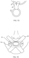
- the engagement can hold a connector that includes sockets 50 that lead up to the patient's nose 185 and attaches to posts 20 that are adhered to nostrils 3.
- the assembly can include swivel ring 190 comprising a connector tubing such as branched tubing 195 that is connected to sockets 50.
- the sockets releasably connect with posts 20 attached to patient nostrils 3.
- the oral assembly can include foam layer 200 positioned between the patient's lips and device external plate 140 to help the device seal against the skin and to increase user comfort during use.
- the foam layer can be created in any desired shape, such as round with central aperture 201 to allow fluid to pass into the patient's oral passageway.
- foam layer 200 can be a cushion.
- tape 205 can be used to surround the exterior plate against the skin. For example, the tape can cross over the mouth in a variety of ways to create a seal.
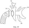
- Fig. 7f illustrates a further embodiment of oral assembly 135 capable of releasably attaching to a fluid source (such as the tubing of a CPAP machine).
- the oral assembly includes hollow gasket 210 that can be constructed from a wide variety of materials, such as (but not limited to) silicone.
- the gasket can form a part of external plate 140, as shown in Fig. 7f .
- the gasket is connected to interior and exterior plates via passageway 150.
- the gasket includes recess 215, sized and shaped to connect to the fluid source.
- the gasket and the fluid source tubing can be connected by snap fit, screw fit, friction fit, or magnetic attachment.
- oral assembly 135 can be connected to tubing 10 to allow the flow of fluid from a fluid source, through the tubing and into the mouthpiece.
- the internal plate is then inserted into the patient's oral cavity, between the patient's teeth and lips.
- the external plate is positioned against the exterior of the patient's mouth, directly adjacent to the patient's lips.
- a sheet comprising an adhesive can be used to attach external plate 140 to the patient's mouth.
- an adhesive can be directly applied to the patient's skin (e.g., in areas near the mouth opening and the lip) or to the skin-facing side of the external plate without the use of a sheet. In this way, the oral assembly remains properly positioned and does not shift or fall out of the mouth. Fluid then flows from the fluid source, through tubing 10 and into the mouthpiece assembly. Particularly, fluid flows from the tubing and into passageway 150, through the first and second plates to exit 160 into the patient's oral cavity.
- the patient When the patient desires to remove the mouthpiece assembly, he simply removes the exterior plate from his lips by grasping the sheet and removing it from the exterior plate. The patient is then free to remove the mouthpiece from his mouth. The mouthpiece can be removed from the tubing for cleaning and/or replacement through joint 155.
- the oral and nasal assemblies can be used alone or in conjunction with each other.
- the respiratory assembly can include a nasal cannula fitted with one or more posts and/or gaskets and can be directly connected to a fluid source.
- the respiratory assembly can include an oral assembly (e.g., mouthpiece or a mask) that is directly connected to a fluid source.
- the respiratory assembly can include a nasal assembly and an oral assembly used in conjunction, such as through a joint connection to a gasket.
- the respiratory assembly described herein has three distinct modes of operation: one in which treatment gases are being supplied to the patient's mouth only, one in which treatment gases are being supplied to the patient's nose only, and one in which treatment gases are being supplied to the patient's nose and mouth.
- the respiratory assembly disclosed herein has a wide variety of applications.
- the assembly can be used for high flow delivery of respirator gas via nasal cannula.
- the air can be heated to near body temperature (e.g., about 37°C) and/or humidified (e.g., about 100% relative humidity) to decrease airway moisture loss, airway cooling, nasal irritation, and the like.
- the source of oxygen is typically blended with compressed air, allowing the delivery of air, blends of air and oxygen from about 22% to about 99%, or delivery of 100% oxygen with the use of an oxygen blender.
- the disclosed assembly includes tubing large enough to deliver flow rate of respiratory gas of up to about 50 liters per minute for adults.
- the nasal cannula is also small enough to prevent sealing of the nares, allowing flow during exhalation and allowing the escape of excess gas during inhalation. Beneficially, because the delivered flow rate can meet the inspiration flow rate, the delivered gases are not diluted by room air.
- the disclosed respiratory assembly can be used with a continuous positive airway pressure (CPAP) machine.
- CPAP machines typically apply mild air pressure on a continuous basis to keep a patient's airway continuously open.
- CPAP machines used in conjunction with a patient's stent can advantageously cause the lungs' alveoli to open and thus recruit more of the lung's surface area for ventilation.
- CPAP machines are generally used for people with breathing problems, such as sleep apnea.
- CPAP machines can be used to treat pre-term infants whose lungs have not yet fully developed.
- the disclosed assembly can be used as a replacement for traditional CPAP masks.
- the disclosed respiratory assembly can further be used in pressure recording applications in clinical settings, such as to diagnose sleep apnea or other disorders. Particularly, sleep apnea can be diagnosed based on characteristic clinical features associated with episodes of cessation of breathing that define hypopnoeic and apnoeic events.
- the disclosed device can be used to measure nasal pressure by measuring nasal pressure with nasal prongs connected to a pressure transducer.
- the disclosed assembly can further be used with a fluid tank, a humidifier, or any other fluid source known or used in the art.
- the disclosed assembly may eliminate over-the-ear soreness and lip soreness commonly found in traditional respiratory masks and cannula.
- the disclosed assembly may enable better control of gases (e.g., oxygen) during fluid delivery applications.
- the assembly of the invention is strapless and maskless, thereby increasing using comfort. As a result, patients are more likely to follow doctor's orders and use the assembly. In addition, unsightly mask and strap skin indentations are eliminated.
- the disclosed assembly is less likely to be dislodged inadvertently by the patient, such as during movement or when being pressed against a pillow.
- the disclosed respiratory assembly includes a sanitizing enclosure that can be used to sanitize the reusable portions of the CPAP assembly.
- sanitizing refers to the elimination of all or nearly all microbial forms.
- enclosure 200 can be defined by a pair of opposing sidewalls 205, opposing front and rear walls 210, 215, bottom wall 220, and hinged lid 225 disposed on the top of the enclosure for providing access to interior 230. It should be appreciated that lid 225 can be attached to the enclosure using any mechanical element, and is not limited to hinges 235.
- the lid can be completely removed from the enclosure.
- Sidewalls 205 and/or front wall 210 can include aperture 240 positioned adjacent to the lid.
- the aperture is sized and shaped to allow attached tubing 245 (see Figs. A and 9b) to pass from the interior through the sidewall when the lid is closed, as shown, for example, in Fig. 9b .
- Aperture 240 can allow a tight fit with tubing 245 such that no UV light and/or activated oxygen generated within the enclosure interior can escape during sanitizing applications.
- enclosure 200 includes an activated oxygen and/or UV light generator 250 that is used to clean and/or sanitize the reusable CPAP elements.
- generator 250 can generate activated oxygen to sanitize the contents of interior 230 and the reusable CPAP system, as discussed in detail below.
- Activated oxygen also known as O3 or ozone
- O3 or ozone is a safe, naturally-occurring gas that has been shown to kill virtually all known forms of viruses in water and air.
- activated oxygen has been shown to interfere with the metabolism of bacterium cells, likely through inhibiting and blocking the operation of the enzymatic control system. A sufficient amount of activated oxygen breaks through the cell membrane, leading to destruction of the bacteria.
- Activated oxygen destroys viruses by diffusing through the protein coat into the nucleic acid core, resulting in damage to the viral RNA. At higher concentrations, activated oxygen destroys the viral capsid by oxidation to affect the DNA or RNA structure. Activated oxygen has been shown to be effective in destroying dozens of harmful pathogens, including E. coli, influenza virus, Staphlococus, Streptococcus bacteria, Stomatitis virus, and many more.
- generator 250 can produce activated oxygen in a concentration of about 10-500 ppm (parts per million) within the interior and/or within the disclosed system.
- generator 250 can produce UV light to sanitize the contents of interior 230 and the associated CPAP equipment.
- generator 250 can include one or more ultraviolet lights that can be activated for a pre-set time period.
- UV light is highly effective at deactivating microorganisms, including bacteria, viruses, yeasts, and molds.
- the UV light is in the range of about 100-280 nanometers which is known to damage the DNA molecules in bacteria, viruses, molds, yeasts, and other microorganisms, preventing them from replicating and causing harm.
- one or more reusable portions of the CPAP assembly can be positioned within enclosure interior 230.
- lid 225 can be opened and sockets 50 connected to tubing 245 can be positioned within enclosure interior 230.
- Tubing 245 can be positioned to extend from the enclosure interior, through aperture 240, to the exterior of the enclosure, and the lid can then be closed, as shown in Fig. 9b .
- tubing 245 can be a flexible tubing.
- Generator 250 can then be activated to generate ozone and/or UV light to sanitize the contents of interior 230 (e.g., sockets 50). In some embodiments, closing of lid 225 automatically triggers activation of generator 250. Alternatively, the generator can be programmed to delay start of activation.
- the activated ozone and/or UV light travels through tubing 10 into humidifier 255 (illustrated in Fig. 9c ) and CPAP chamber 260 (also illustrated in Fig. 9c ), as shown by the arrows of Fig. 9c .
- the generator will continue to produce UV light and/or activated oxygen for a pre-set period of time until the respiratory assembly has been sufficiently sterilized.
- the enclosure acts as a closed-loop system by generating activated oxygen and/or UV light to sanitize CPAP equipment without releasing the activated oxygen and/or UV light into the air surrounding the enclosure.
- the enclosure can be equipped with one or more air flow mechanisms that assist circulation of the activated oxygen and/or UV light. Residual activated oxygen and/or UV light that remains in the system naturally reverts back into breathable air within a designated time period (e.g., 2 hours). After the sanitizing has completed, the CPAP equipment will be ready to use.
- the sanitizing enclosure starts automatically after the user places the equipment within interior 230 and closes lid 225.
- the sanitizing can be delayed by programming a desired later time.
- enclosure 200 can include an indicator light that will illuminate during the sanitizing process to signify to the user that sanitizing process is ongoing.
- Lid 225 can remain locked during sanitizing to prevent the user from unintentional exposure to the UV light and/or activated oxygen.
- the lid can automatically unlock in one embodiment.
- Sanitizing enclosure 200 can kill about 99% of mold, bacteria, and viruses in the CPAP user's sockets (or mask), tubing, humidifier, and CPAP chamber.
- the sanitizing enclosure is designed for ease of use. Users simply place their sockets or mask in the sanitizing enclosure, close the lid, and walk away. Importantly, no disassembly of the CPAP apparatus is required prior to start of the sanitizing process.
- the sanitizing enclosure can be used daily. In one embodiment, the sanitizing enclosure is configured to support several sanitization cycles to be carried out per day.
- enclosure 200 can be permanently attached to a CPAP unit including CPAP chamber 260, such as through the use of mechanical elements (screws, bolts, hooks, pins, and the like), adhesives, etc.
- the enclosure can be formed as part of a CPAP unit (i.e., the enclosure is built into the CPAP design).
- the presently disclosed subject matter also includes embodiments wherein enclosure 200 can be removably attached to the CPAP unit (e.g., via snap-fit, magnetic attachment, friction fit) or is configured as a stand-alone element.
- enclosure 200 can be configured in any desired shape, such as circular, oval, square, triangular, oval, hexagonal, pentagonal, star, abstract, and the like.
- the enclosure can be configured in any desired size.
- the enclosure can have a relatively small size, compared to the size of the CPAP assembly.
- the enclosure can have a height, width, and depth of less than about 5 inches, such as no more than about 5.0, 4.75, 4.5, 4.25, 4.0, 3.75, 3.5, 3.25, 3.0, 2.75, 2.5, 2.25, 2.0, 1.75, 1.5, 1.25, or 1.0 inches.
- enclosure 200 can have any desired size to accommodate a particular CPAP element within its interior.
Landscapes
- Health & Medical Sciences (AREA)
- Pulmonology (AREA)
- Life Sciences & Earth Sciences (AREA)
- Veterinary Medicine (AREA)
- Public Health (AREA)
- General Health & Medical Sciences (AREA)
- Animal Behavior & Ethology (AREA)
- Biomedical Technology (AREA)
- Hematology (AREA)
- Heart & Thoracic Surgery (AREA)
- Anesthesiology (AREA)
- Engineering & Computer Science (AREA)
- Emergency Medicine (AREA)
- Otolaryngology (AREA)
- Epidemiology (AREA)
- Chemical Kinetics & Catalysis (AREA)
- General Chemical & Material Sciences (AREA)
- Chemical & Material Sciences (AREA)
- Respiratory Apparatuses And Protective Means (AREA)
- Media Introduction/Drainage Providing Device (AREA)
- Infusion, Injection, And Reservoir Apparatuses (AREA)
Claims (14)
- Ensemble respiratoire nasal (5), comprenant :un tube flexible (10) connecté à une source de fluide, dans lequel le tube flexible (10) comprend un segment présentant une paire de réceptacles (15) dirigés radialement s'étendant à partir de celui-ci, chaque réceptacle présentant une extrémité de sortie (16) à travers laquelle du fluide provenant de la source de fluide est distribué ; etune paire de montants (20) ; dans lequel chaque montant (20) comprend une bride (25) dimensionnée et formée pour se fixer à une partie extérieure de la narine d'un patient ;un corps principal (30) comprenant un passage (36) en son intérieur ; etun connecteur (35) avec une ouverture centrale (36) dimensionnée et mise en forme pour permettre une insertion amovible de l'extrémité de sortie (16) de l'un des réceptacles (15),dans lequel l'ensemble respiratoire nasal (5) est sans masque et sans bretelles.
- Ensemble selon la revendication 1, dans lequel le tube flexible (10) présente un diamètre intérieur d'environ 2 à 4 mm.
- Ensemble selon la revendication 1, dans lequel la source de fluide est choisie parmi un générateur à écoulement élevée, une machine à pression positive continue des voies aériennes, « CPAP », un réservoir de fluide ou un humidificateur.
- Ensemble selon la revendication 1, dans lequel le fluide est un gaz avec un médicament.
- Ensemble selon la revendication 1, dans lequel la bride (25) forme un angle.
- Ensemble selon la revendication 5, dans lequel l'angle est compris entre environ 0 degré et environ 45 degrés.
- Ensemble selon la revendication 1, dans lequel le connecteur (35) des montants (20) comprend une nervure.
- Ensemble selon la revendication 1, dans lequel les réceptacles (15) comprennent chacun une douille (50).
- Ensemble selon la revendication 8, dans lequel la douille (50) comprend :un collier (65) positionné au niveau d'une première extrémité ;un adaptateur (67) positionné au niveau d'une seconde extrémité ;un passage (90) s'étendant à partir de la première jusqu'à la seconde extrémité ;une cavité (70) positionnée au niveau de la première extrémité, dimensionnée et mise en forme pour loger de manière libérable le connecteur (35) et au moins une partie du corps de montant (30) en son sein.
- Ensemble selon la revendication 9,
dans lequel le collier (65) comprend une ou plusieurs libérations (55) qui peuvent être pivotées pour maintenir ou libérer le montant (20) à l'intérieur de la cavité (70). - Ensemble selon la revendication 1, dans lequel la bride (25) est collée directement à la partie extérieure d'une narine.
- Ensemble selon la revendication 1, dans lequel le tube (10) est disposé sur les oreilles pendant une utilisation.
- Ensemble selon la revendication 1, dans lequel les réceptacles (15) sont disposés parallèlement les uns par rapport aux autres.
- Ensemble selon la revendication 1, dans lequel l'extrémité de sortie (16) de chaque réceptacle (15) inséré dans le montant (20) s'étend à l'écart du montant (20) pour s'étendre jusque dans la narine d'un patient.
Priority Applications (1)
| Application Number | Priority Date | Filing Date | Title |
|---|---|---|---|
| EP24200400.0A EP4454667B1 (fr) | 2018-02-08 | 2019-02-04 | Ensemble oral |
Applications Claiming Priority (3)
| Application Number | Priority Date | Filing Date | Title |
|---|---|---|---|
| US201862627800P | 2018-02-08 | 2018-02-08 | |
| US201862640633P | 2018-03-09 | 2018-03-09 | |
| PCT/US2019/016478 WO2019156921A1 (fr) | 2018-02-08 | 2019-02-04 | Ensemble respiratoire auto-désinfectant et procédés de fabrication et d'utilisation de celui-ci |
Related Child Applications (1)
| Application Number | Title | Priority Date | Filing Date |
|---|---|---|---|
| EP24200400.0A Division EP4454667B1 (fr) | 2018-02-08 | 2019-02-04 | Ensemble oral |
Publications (3)
| Publication Number | Publication Date |
|---|---|
| EP3749403A1 EP3749403A1 (fr) | 2020-12-16 |
| EP3749403A4 EP3749403A4 (fr) | 2022-02-16 |
| EP3749403B1 true EP3749403B1 (fr) | 2024-09-18 |
Family
ID=67549072
Family Applications (2)
| Application Number | Title | Priority Date | Filing Date |
|---|---|---|---|
| EP24200400.0A Active EP4454667B1 (fr) | 2018-02-08 | 2019-02-04 | Ensemble oral |
| EP19750901.1A Active EP3749403B1 (fr) | 2018-02-08 | 2019-02-04 | Ensemble respiratoire nasal |
Family Applications Before (1)
| Application Number | Title | Priority Date | Filing Date |
|---|---|---|---|
| EP24200400.0A Active EP4454667B1 (fr) | 2018-02-08 | 2019-02-04 | Ensemble oral |
Country Status (4)
| Country | Link |
|---|---|
| US (2) | US11833306B2 (fr) |
| EP (2) | EP4454667B1 (fr) |
| CA (1) | CA3090273A1 (fr) |
| WO (1) | WO2019156921A1 (fr) |
Families Citing this family (12)
| Publication number | Priority date | Publication date | Assignee | Title |
|---|---|---|---|---|
| US11207484B2 (en) | 2011-11-21 | 2021-12-28 | Snap Cpap, Llc | Respiratory assembly |
| US12109429B2 (en) | 2015-07-28 | 2024-10-08 | Know Bio, Llc | Phototherapeutic light for treatment of pathogens |
| CN108136196B (zh) | 2015-07-28 | 2020-07-17 | 诺欧生物有限责任公司 | 用于对一氧化氮的光疗调节的系统和方法 |
| US11147984B2 (en) | 2020-03-19 | 2021-10-19 | Know Bio, Llc | Illumination devices for inducing biological effects |
| US11986666B2 (en) | 2020-03-19 | 2024-05-21 | Know Bio, Llc | Illumination devices for inducing biological effects |
| US12011611B2 (en) | 2020-03-19 | 2024-06-18 | Know Bio, Llc | Illumination devices for inducing biological effects |
| US12447354B2 (en) | 2020-03-19 | 2025-10-21 | Know Bio, Llc | Illumination devices for inducing biological effects |
| US20220331472A1 (en) * | 2020-03-29 | 2022-10-20 | Dynamics Inc. | Large-scale uv-c inactivation devices and simulations of the same |
| IT202000011017A1 (it) * | 2020-05-14 | 2021-11-14 | Lucio Filippelli | Metodo di esecuzione di spirometria e sistema per la realizzazione di detto metodo |
| US12347337B2 (en) | 2020-12-10 | 2025-07-01 | Know Bio, Llc | Enhanced testing and characterization techniques for phototherapeutic light treatments |
| US12115384B2 (en) | 2021-03-15 | 2024-10-15 | Know Bio, Llc | Devices and methods for illuminating tissue to induce biological effects |
| US11654294B2 (en) | 2021-03-15 | 2023-05-23 | Know Bio, Llc | Intranasal illumination devices |
Citations (3)
| Publication number | Priority date | Publication date | Assignee | Title |
|---|---|---|---|---|
| EP0821978A2 (fr) * | 1996-07-30 | 1998-02-04 | Hart-Ellereth Medical Inc. | Appareil léger pour la ventilation en pression positive |
| US20160022947A1 (en) * | 2011-11-21 | 2016-01-28 | Stuart Heatherington | Respiratory assembly |
| WO2017062677A1 (fr) * | 2015-10-06 | 2017-04-13 | Snap Cpap, Llc | Ensemble respiratoire |
Family Cites Families (25)
| Publication number | Priority date | Publication date | Assignee | Title |
|---|---|---|---|---|
| US4315505A (en) * | 1980-04-07 | 1982-02-16 | Shiley, Inc. | Tracheostomy tube with disposable inner cannula |
| SE464169B (sv) * | 1988-09-19 | 1991-03-18 | Foereningen Lim Infektionsklin | Munstycke foer anslutning till en respirator |
| US5797627A (en) * | 1995-02-28 | 1998-08-25 | Salter Labs | Swivel |
| EP1075848B1 (fr) * | 1999-08-10 | 2005-11-16 | Fisher & Paykel Healthcare Limited | Embout buccal avec moyens d'étanchéité extra-oraux pliables |
| US20020069872A1 (en) * | 2000-09-22 | 2002-06-13 | Gradon Lewis George | Mouthpiece |
| US9155855B2 (en) * | 2002-12-06 | 2015-10-13 | Fisher & Paykel Healthcare Limited | Mouthpiece |
| US7178525B2 (en) * | 2004-02-06 | 2007-02-20 | Ric Investments, Llc | Patient interface assembly supported under the mandible |
| US7856982B2 (en) * | 2004-03-11 | 2010-12-28 | Ric Investments, Llc | Patient interface device |
| GB0520614D0 (en) * | 2005-10-11 | 2005-11-16 | Lifelab Innovations Ltd | Respiratory protection device |
| US7987851B2 (en) * | 2005-12-27 | 2011-08-02 | Hansa Medical Products, Inc. | Valved fenestrated tracheotomy tube having outer and inner cannulae |
| TW200836781A (en) * | 2007-03-07 | 2008-09-16 | Ventus Medical Inc | Nasal devices |
| US20080216841A1 (en) * | 2007-03-08 | 2008-09-11 | Grimes Beverly S | Nasal cannula |
| US20090095303A1 (en) | 2007-10-16 | 2009-04-16 | Bruce Sher | Nasal prongs |
| DE112008003064T5 (de) * | 2007-11-16 | 2010-12-09 | Fisher & Paykel Healthcare Ltd., East Tamaki | Nasenolive mit hochvolumiger Bypassströmung und Verfahren zu deren Verwendung |
| WO2009089239A2 (fr) * | 2008-01-07 | 2009-07-16 | Mergenet Solutions, Inc. | Interface de ventilation nasale |
| US9132250B2 (en) * | 2009-09-03 | 2015-09-15 | Breathe Technologies, Inc. | Methods, systems and devices for non-invasive ventilation including a non-sealing ventilation interface with an entrainment port and/or pressure feature |
| EP3231470B1 (fr) * | 2010-09-30 | 2023-01-11 | ResMed Pty Ltd | Système de masque |
| US20160206303A1 (en) * | 2013-09-17 | 2016-07-21 | H. Lee Moffitt Cancer Center And Research Institute, Inc. | Orogastric tube guide |
| US10758694B2 (en) * | 2015-07-09 | 2020-09-01 | Hoyt Medical LLC | Systems and methods for treating an airway using a tapered adapter device |
| US10322252B2 (en) * | 2015-07-10 | 2019-06-18 | Darin B Atherton | Ergonomic nasal cannula |
| JP6632834B2 (ja) | 2015-08-24 | 2020-01-22 | スタンレー電気株式会社 | 発光装置 |
| US10568757B2 (en) * | 2016-01-22 | 2020-02-25 | Achaemenid, Llc | Hybrid oral device |
| US10010718B2 (en) * | 2016-04-01 | 2018-07-03 | Mohamed A Basiony | Device to kill micro-organisms inside the respiratory tract |
| EP3246064A1 (fr) * | 2016-05-16 | 2017-11-22 | L'air Liquide, Societe Anonyme Pour L'etude Et L'exploitation Des Procedes Georges Claude | Canule nasale |
| US11638798B2 (en) * | 2016-10-13 | 2023-05-02 | Vyaire Medical Capital, LLC | Nasal cannula systems and methods |
-
2019
- 2019-02-04 EP EP24200400.0A patent/EP4454667B1/fr active Active
- 2019-02-04 WO PCT/US2019/016478 patent/WO2019156921A1/fr not_active Ceased
- 2019-02-04 CA CA3090273A patent/CA3090273A1/fr active Pending
- 2019-02-04 EP EP19750901.1A patent/EP3749403B1/fr active Active
-
2020
- 2020-07-30 US US16/943,386 patent/US11833306B2/en active Active
-
2023
- 2023-12-04 US US18/527,858 patent/US12472324B2/en active Active
Patent Citations (3)
| Publication number | Priority date | Publication date | Assignee | Title |
|---|---|---|---|---|
| EP0821978A2 (fr) * | 1996-07-30 | 1998-02-04 | Hart-Ellereth Medical Inc. | Appareil léger pour la ventilation en pression positive |
| US20160022947A1 (en) * | 2011-11-21 | 2016-01-28 | Stuart Heatherington | Respiratory assembly |
| WO2017062677A1 (fr) * | 2015-10-06 | 2017-04-13 | Snap Cpap, Llc | Ensemble respiratoire |
Also Published As
| Publication number | Publication date |
|---|---|
| US20240100281A1 (en) | 2024-03-28 |
| EP4454667A3 (fr) | 2025-01-15 |
| WO2019156921A1 (fr) | 2019-08-15 |
| EP3749403A4 (fr) | 2022-02-16 |
| EP4454667A2 (fr) | 2024-10-30 |
| CA3090273A1 (fr) | 2019-08-15 |
| EP3749403A1 (fr) | 2020-12-16 |
| EP4454667B1 (fr) | 2026-04-15 |
| US20200353195A1 (en) | 2020-11-12 |
| US12472324B2 (en) | 2025-11-18 |
| US11833306B2 (en) | 2023-12-05 |
Similar Documents
| Publication | Publication Date | Title |
|---|---|---|
| US12472324B2 (en) | Self-sanitizing respiratory assembly and methods of making and using the same | |
| US12201776B2 (en) | Apparatus for use in a respiratory support system | |
| US11925760B2 (en) | Respiratory assembly and methods of using the same | |
| US12465712B2 (en) | Respiratory assembly with conduit adapter and methods of use | |
| JP4895419B2 (ja) | マウスピース及び気体を経口的に供給するために使用可能な装置 | |
| US20220088338A1 (en) | Respiratory assembly and methods of using the same |
Legal Events
| Date | Code | Title | Description |
|---|---|---|---|
| STAA | Information on the status of an ep patent application or granted ep patent |
Free format text: STATUS: THE INTERNATIONAL PUBLICATION HAS BEEN MADE |
|
| PUAI | Public reference made under article 153(3) epc to a published international application that has entered the european phase |
Free format text: ORIGINAL CODE: 0009012 |
|
| STAA | Information on the status of an ep patent application or granted ep patent |
Free format text: STATUS: REQUEST FOR EXAMINATION WAS MADE |
|
| 17P | Request for examination filed |
Effective date: 20200907 |
|
| AK | Designated contracting states |
Kind code of ref document: A1 Designated state(s): AL AT BE BG CH CY CZ DE DK EE ES FI FR GB GR HR HU IE IS IT LI LT LU LV MC MK MT NL NO PL PT RO RS SE SI SK SM TR |
|
| AX | Request for extension of the european patent |
Extension state: BA ME |
|
| DAV | Request for validation of the european patent (deleted) | ||
| DAX | Request for extension of the european patent (deleted) | ||
| RIC1 | Information provided on ipc code assigned before grant |
Ipc: A61L 2/10 20060101ALI20210928BHEP Ipc: A61M 16/10 20060101ALI20210928BHEP Ipc: A61M 16/04 20060101ALI20210928BHEP Ipc: A61M 16/08 20060101ALI20210928BHEP Ipc: A61M 16/06 20060101AFI20210928BHEP |
|
| A4 | Supplementary search report drawn up and despatched |
Effective date: 20220113 |
|
| RIC1 | Information provided on ipc code assigned before grant |
Ipc: A61L 2/10 20060101ALI20220107BHEP Ipc: A61M 16/10 20060101ALI20220107BHEP Ipc: A61M 16/04 20060101ALI20220107BHEP Ipc: A61M 16/08 20060101ALI20220107BHEP Ipc: A61M 16/06 20060101AFI20220107BHEP |
|
| STAA | Information on the status of an ep patent application or granted ep patent |
Free format text: STATUS: EXAMINATION IS IN PROGRESS |
|
| 17Q | First examination report despatched |
Effective date: 20230328 |
|
| GRAP | Despatch of communication of intention to grant a patent |
Free format text: ORIGINAL CODE: EPIDOSNIGR1 |
|
| STAA | Information on the status of an ep patent application or granted ep patent |
Free format text: STATUS: GRANT OF PATENT IS INTENDED |
|
| INTG | Intention to grant announced |
Effective date: 20231214 |
|
| GRAJ | Information related to disapproval of communication of intention to grant by the applicant or resumption of examination proceedings by the epo deleted |
Free format text: ORIGINAL CODE: EPIDOSDIGR1 |
|
| STAA | Information on the status of an ep patent application or granted ep patent |
Free format text: STATUS: EXAMINATION IS IN PROGRESS |
|
| RAP3 | Party data changed (applicant data changed or rights of an application transferred) |
Owner name: SNAP CPAP, LLC |
|
| RIN1 | Information on inventor provided before grant (corrected) |
Inventor name: HEATHERINGTON, STUART |
|
| GRAP | Despatch of communication of intention to grant a patent |
Free format text: ORIGINAL CODE: EPIDOSNIGR1 |
|
| STAA | Information on the status of an ep patent application or granted ep patent |
Free format text: STATUS: GRANT OF PATENT IS INTENDED |
|
| INTG | Intention to grant announced |
Effective date: 20240419 |
|
| GRAS | Grant fee paid |
Free format text: ORIGINAL CODE: EPIDOSNIGR3 |
|
| GRAA | (expected) grant |
Free format text: ORIGINAL CODE: 0009210 |
|
| STAA | Information on the status of an ep patent application or granted ep patent |
Free format text: STATUS: THE PATENT HAS BEEN GRANTED |
|
| AK | Designated contracting states |
Kind code of ref document: B1 Designated state(s): AL AT BE BG CH CY CZ DE DK EE ES FI FR GB GR HR HU IE IS IT LI LT LU LV MC MK MT NL NO PL PT RO RS SE SI SK SM TR |
|
| REG | Reference to a national code |
Ref country code: GB Ref legal event code: FG4D |
|
| REG | Reference to a national code |
Ref country code: CH Ref legal event code: EP |
|
| REG | Reference to a national code |
Ref country code: DE Ref legal event code: R096 Ref document number: 602019059101 Country of ref document: DE |
|
| REG | Reference to a national code |
Ref country code: IE Ref legal event code: FG4D |
|
| P01 | Opt-out of the competence of the unified patent court (upc) registered |
Free format text: CASE NUMBER: APP_57936/2024 Effective date: 20241023 |
|
| REG | Reference to a national code |
Ref country code: LT Ref legal event code: MG9D |
|
| PG25 | Lapsed in a contracting state [announced via postgrant information from national office to epo] |
Ref country code: NO Free format text: LAPSE BECAUSE OF FAILURE TO SUBMIT A TRANSLATION OF THE DESCRIPTION OR TO PAY THE FEE WITHIN THE PRESCRIBED TIME-LIMIT Effective date: 20241218 |
|
| PG25 | Lapsed in a contracting state [announced via postgrant information from national office to epo] |
Ref country code: GR Free format text: LAPSE BECAUSE OF FAILURE TO SUBMIT A TRANSLATION OF THE DESCRIPTION OR TO PAY THE FEE WITHIN THE PRESCRIBED TIME-LIMIT Effective date: 20241219 Ref country code: FI Free format text: LAPSE BECAUSE OF FAILURE TO SUBMIT A TRANSLATION OF THE DESCRIPTION OR TO PAY THE FEE WITHIN THE PRESCRIBED TIME-LIMIT Effective date: 20240918 |
|
| PG25 | Lapsed in a contracting state [announced via postgrant information from national office to epo] |
Ref country code: BG Free format text: LAPSE BECAUSE OF FAILURE TO SUBMIT A TRANSLATION OF THE DESCRIPTION OR TO PAY THE FEE WITHIN THE PRESCRIBED TIME-LIMIT Effective date: 20240918 |
|
| PG25 | Lapsed in a contracting state [announced via postgrant information from national office to epo] |
Ref country code: LV Free format text: LAPSE BECAUSE OF FAILURE TO SUBMIT A TRANSLATION OF THE DESCRIPTION OR TO PAY THE FEE WITHIN THE PRESCRIBED TIME-LIMIT Effective date: 20240918 |
|
| PG25 | Lapsed in a contracting state [announced via postgrant information from national office to epo] |
Ref country code: HR Free format text: LAPSE BECAUSE OF FAILURE TO SUBMIT A TRANSLATION OF THE DESCRIPTION OR TO PAY THE FEE WITHIN THE PRESCRIBED TIME-LIMIT Effective date: 20240918 |
|
| REG | Reference to a national code |
Ref country code: NL Ref legal event code: MP Effective date: 20240918 |
|
| PG25 | Lapsed in a contracting state [announced via postgrant information from national office to epo] |
Ref country code: RS Free format text: LAPSE BECAUSE OF FAILURE TO SUBMIT A TRANSLATION OF THE DESCRIPTION OR TO PAY THE FEE WITHIN THE PRESCRIBED TIME-LIMIT Effective date: 20241218 |
|
| PG25 | Lapsed in a contracting state [announced via postgrant information from national office to epo] |
Ref country code: RS Free format text: LAPSE BECAUSE OF FAILURE TO SUBMIT A TRANSLATION OF THE DESCRIPTION OR TO PAY THE FEE WITHIN THE PRESCRIBED TIME-LIMIT Effective date: 20241218 Ref country code: NO Free format text: LAPSE BECAUSE OF FAILURE TO SUBMIT A TRANSLATION OF THE DESCRIPTION OR TO PAY THE FEE WITHIN THE PRESCRIBED TIME-LIMIT Effective date: 20241218 Ref country code: LV Free format text: LAPSE BECAUSE OF FAILURE TO SUBMIT A TRANSLATION OF THE DESCRIPTION OR TO PAY THE FEE WITHIN THE PRESCRIBED TIME-LIMIT Effective date: 20240918 Ref country code: HR Free format text: LAPSE BECAUSE OF FAILURE TO SUBMIT A TRANSLATION OF THE DESCRIPTION OR TO PAY THE FEE WITHIN THE PRESCRIBED TIME-LIMIT Effective date: 20240918 Ref country code: GR Free format text: LAPSE BECAUSE OF FAILURE TO SUBMIT A TRANSLATION OF THE DESCRIPTION OR TO PAY THE FEE WITHIN THE PRESCRIBED TIME-LIMIT Effective date: 20241219 Ref country code: FI Free format text: LAPSE BECAUSE OF FAILURE TO SUBMIT A TRANSLATION OF THE DESCRIPTION OR TO PAY THE FEE WITHIN THE PRESCRIBED TIME-LIMIT Effective date: 20240918 Ref country code: BG Free format text: LAPSE BECAUSE OF FAILURE TO SUBMIT A TRANSLATION OF THE DESCRIPTION OR TO PAY THE FEE WITHIN THE PRESCRIBED TIME-LIMIT Effective date: 20240918 |
|
| REG | Reference to a national code |
Ref country code: AT Ref legal event code: MK05 Ref document number: 1724170 Country of ref document: AT Kind code of ref document: T Effective date: 20240918 |
|
| PG25 | Lapsed in a contracting state [announced via postgrant information from national office to epo] |
Ref country code: NL Free format text: LAPSE BECAUSE OF FAILURE TO SUBMIT A TRANSLATION OF THE DESCRIPTION OR TO PAY THE FEE WITHIN THE PRESCRIBED TIME-LIMIT Effective date: 20240918 |
|
| PG25 | Lapsed in a contracting state [announced via postgrant information from national office to epo] |
Ref country code: IS Free format text: LAPSE BECAUSE OF FAILURE TO SUBMIT A TRANSLATION OF THE DESCRIPTION OR TO PAY THE FEE WITHIN THE PRESCRIBED TIME-LIMIT Effective date: 20250118 Ref country code: PT Free format text: LAPSE BECAUSE OF FAILURE TO SUBMIT A TRANSLATION OF THE DESCRIPTION OR TO PAY THE FEE WITHIN THE PRESCRIBED TIME-LIMIT Effective date: 20250120 |
|
| PG25 | Lapsed in a contracting state [announced via postgrant information from national office to epo] |
Ref country code: SM Free format text: LAPSE BECAUSE OF FAILURE TO SUBMIT A TRANSLATION OF THE DESCRIPTION OR TO PAY THE FEE WITHIN THE PRESCRIBED TIME-LIMIT Effective date: 20240918 Ref country code: RO Free format text: LAPSE BECAUSE OF FAILURE TO SUBMIT A TRANSLATION OF THE DESCRIPTION OR TO PAY THE FEE WITHIN THE PRESCRIBED TIME-LIMIT Effective date: 20240918 |
|
| PG25 | Lapsed in a contracting state [announced via postgrant information from national office to epo] |
Ref country code: ES Free format text: LAPSE BECAUSE OF FAILURE TO SUBMIT A TRANSLATION OF THE DESCRIPTION OR TO PAY THE FEE WITHIN THE PRESCRIBED TIME-LIMIT Effective date: 20240918 |
|
| PG25 | Lapsed in a contracting state [announced via postgrant information from national office to epo] |
Ref country code: EE Free format text: LAPSE BECAUSE OF FAILURE TO SUBMIT A TRANSLATION OF THE DESCRIPTION OR TO PAY THE FEE WITHIN THE PRESCRIBED TIME-LIMIT Effective date: 20240918 Ref country code: AT Free format text: LAPSE BECAUSE OF FAILURE TO SUBMIT A TRANSLATION OF THE DESCRIPTION OR TO PAY THE FEE WITHIN THE PRESCRIBED TIME-LIMIT Effective date: 20240918 |
|
| PG25 | Lapsed in a contracting state [announced via postgrant information from national office to epo] |
Ref country code: CZ Free format text: LAPSE BECAUSE OF FAILURE TO SUBMIT A TRANSLATION OF THE DESCRIPTION OR TO PAY THE FEE WITHIN THE PRESCRIBED TIME-LIMIT Effective date: 20240918 Ref country code: PL Free format text: LAPSE BECAUSE OF FAILURE TO SUBMIT A TRANSLATION OF THE DESCRIPTION OR TO PAY THE FEE WITHIN THE PRESCRIBED TIME-LIMIT Effective date: 20240918 |
|
| PG25 | Lapsed in a contracting state [announced via postgrant information from national office to epo] |
Ref country code: SK Free format text: LAPSE BECAUSE OF FAILURE TO SUBMIT A TRANSLATION OF THE DESCRIPTION OR TO PAY THE FEE WITHIN THE PRESCRIBED TIME-LIMIT Effective date: 20240918 Ref country code: IT Free format text: LAPSE BECAUSE OF FAILURE TO SUBMIT A TRANSLATION OF THE DESCRIPTION OR TO PAY THE FEE WITHIN THE PRESCRIBED TIME-LIMIT Effective date: 20240918 |
|
| REG | Reference to a national code |
Ref country code: DE Ref legal event code: R097 Ref document number: 602019059101 Country of ref document: DE |
|
| PG25 | Lapsed in a contracting state [announced via postgrant information from national office to epo] |
Ref country code: DK Free format text: LAPSE BECAUSE OF FAILURE TO SUBMIT A TRANSLATION OF THE DESCRIPTION OR TO PAY THE FEE WITHIN THE PRESCRIBED TIME-LIMIT Effective date: 20240918 |
|
| PLBE | No opposition filed within time limit |
Free format text: ORIGINAL CODE: 0009261 |
|
| STAA | Information on the status of an ep patent application or granted ep patent |
Free format text: STATUS: NO OPPOSITION FILED WITHIN TIME LIMIT |
|
| 26N | No opposition filed |
Effective date: 20250619 |
|
| PG25 | Lapsed in a contracting state [announced via postgrant information from national office to epo] |
Ref country code: SE Free format text: LAPSE BECAUSE OF FAILURE TO SUBMIT A TRANSLATION OF THE DESCRIPTION OR TO PAY THE FEE WITHIN THE PRESCRIBED TIME-LIMIT Effective date: 20240918 |
|
| PG25 | Lapsed in a contracting state [announced via postgrant information from national office to epo] |
Ref country code: MC Free format text: LAPSE BECAUSE OF FAILURE TO SUBMIT A TRANSLATION OF THE DESCRIPTION OR TO PAY THE FEE WITHIN THE PRESCRIBED TIME-LIMIT Effective date: 20240918 |
|
| REG | Reference to a national code |
Ref country code: CH Ref legal event code: PL |
|
| PG25 | Lapsed in a contracting state [announced via postgrant information from national office to epo] |
Ref country code: LU Free format text: LAPSE BECAUSE OF NON-PAYMENT OF DUE FEES Effective date: 20250204 |
|
| PG25 | Lapsed in a contracting state [announced via postgrant information from national office to epo] |
Ref country code: CH Free format text: LAPSE BECAUSE OF NON-PAYMENT OF DUE FEES Effective date: 20250228 |
|
| REG | Reference to a national code |
Ref country code: BE Ref legal event code: MM Effective date: 20250228 |
|
| PG25 | Lapsed in a contracting state [announced via postgrant information from national office to epo] |
Ref country code: BE Free format text: LAPSE BECAUSE OF NON-PAYMENT OF DUE FEES Effective date: 20250228 |
|
| PG25 | Lapsed in a contracting state [announced via postgrant information from national office to epo] |
Ref country code: IE Free format text: LAPSE BECAUSE OF NON-PAYMENT OF DUE FEES Effective date: 20250204 |
|
| PGFP | Annual fee paid to national office [announced via postgrant information from national office to epo] |
Ref country code: GB Payment date: 20260209 Year of fee payment: 8 |
|
| PGFP | Annual fee paid to national office [announced via postgrant information from national office to epo] |
Ref country code: DE Payment date: 20260209 Year of fee payment: 8 |
|
| PGFP | Annual fee paid to national office [announced via postgrant information from national office to epo] |
Ref country code: FR Payment date: 20260213 Year of fee payment: 8 |