EP3750166B1 - Système de commande de marche avancée et procédés permettant un mouvement de marche continu d'un dispositif d'exosquelette motorisé - Google Patents
Système de commande de marche avancée et procédés permettant un mouvement de marche continu d'un dispositif d'exosquelette motorisé Download PDFInfo
- Publication number
- EP3750166B1 EP3750166B1 EP18724037.9A EP18724037A EP3750166B1 EP 3750166 B1 EP3750166 B1 EP 3750166B1 EP 18724037 A EP18724037 A EP 18724037A EP 3750166 B1 EP3750166 B1 EP 3750166B1
- Authority
- EP
- European Patent Office
- Prior art keywords
- gait
- leg
- stance
- control
- control system
- Prior art date
- Legal status (The legal status is an assumption and is not a legal conclusion. Google has not performed a legal analysis and makes no representation as to the accuracy of the status listed.)
- Active
Links
Images


Classifications
-
- G—PHYSICS
- G16—INFORMATION AND COMMUNICATION TECHNOLOGY [ICT] SPECIALLY ADAPTED FOR SPECIFIC APPLICATION FIELDS
- G16H—HEALTHCARE INFORMATICS, i.e. INFORMATION AND COMMUNICATION TECHNOLOGY [ICT] SPECIALLY ADAPTED FOR THE HANDLING OR PROCESSING OF MEDICAL OR HEALTHCARE DATA
- G16H40/00—ICT specially adapted for the management or administration of healthcare resources or facilities; ICT specially adapted for the management or operation of medical equipment or devices
- G16H40/60—ICT specially adapted for the management or administration of healthcare resources or facilities; ICT specially adapted for the management or operation of medical equipment or devices for the operation of medical equipment or devices
- G16H40/63—ICT specially adapted for the management or administration of healthcare resources or facilities; ICT specially adapted for the management or operation of medical equipment or devices for the operation of medical equipment or devices for local operation
-
- A—HUMAN NECESSITIES
- A61—MEDICAL OR VETERINARY SCIENCE; HYGIENE
- A61H—PHYSICAL THERAPY APPARATUS, e.g. DEVICES FOR LOCATING OR STIMULATING REFLEX POINTS IN THE BODY; ARTIFICIAL RESPIRATION; MASSAGE; BATHING DEVICES FOR SPECIAL THERAPEUTIC OR HYGIENIC PURPOSES OR SPECIFIC PARTS OF THE BODY
- A61H3/00—Appliances for aiding patients or disabled persons to walk about
-
- A—HUMAN NECESSITIES
- A61—MEDICAL OR VETERINARY SCIENCE; HYGIENE
- A61F—FILTERS IMPLANTABLE INTO BLOOD VESSELS; PROSTHESES; DEVICES PROVIDING PATENCY TO, OR PREVENTING COLLAPSING OF, TUBULAR STRUCTURES OF THE BODY, e.g. STENTS; ORTHOPAEDIC, NURSING OR CONTRACEPTIVE DEVICES; FOMENTATION; TREATMENT OR PROTECTION OF EYES OR EARS; BANDAGES, DRESSINGS OR ABSORBENT PADS; FIRST-AID KITS
- A61F2/00—Filters implantable into blood vessels; Prostheses, i.e. artificial substitutes or replacements for parts of the body; Appliances for connecting them with the body; Devices providing patency to, or preventing collapsing of, tubular structures of the body, e.g. stents
- A61F2/50—Prostheses not implantable in the body
- A61F2/68—Operating or control means
- A61F2/70—Operating or control means electrical
-
- A—HUMAN NECESSITIES
- A61—MEDICAL OR VETERINARY SCIENCE; HYGIENE
- A61H—PHYSICAL THERAPY APPARATUS, e.g. DEVICES FOR LOCATING OR STIMULATING REFLEX POINTS IN THE BODY; ARTIFICIAL RESPIRATION; MASSAGE; BATHING DEVICES FOR SPECIAL THERAPEUTIC OR HYGIENIC PURPOSES OR SPECIFIC PARTS OF THE BODY
- A61H1/00—Apparatus for passive exercising; Vibrating apparatus; Chiropractic devices, e.g. body impacting devices, external devices for briefly extending or aligning unbroken bones
- A61H1/02—Stretching or bending or torsioning apparatus for exercising
- A61H1/0237—Stretching or bending or torsioning apparatus for exercising for the lower limbs
- A61H1/024—Knee
-
- A—HUMAN NECESSITIES
- A61—MEDICAL OR VETERINARY SCIENCE; HYGIENE
- A61H—PHYSICAL THERAPY APPARATUS, e.g. DEVICES FOR LOCATING OR STIMULATING REFLEX POINTS IN THE BODY; ARTIFICIAL RESPIRATION; MASSAGE; BATHING DEVICES FOR SPECIAL THERAPEUTIC OR HYGIENIC PURPOSES OR SPECIFIC PARTS OF THE BODY
- A61H1/00—Apparatus for passive exercising; Vibrating apparatus; Chiropractic devices, e.g. body impacting devices, external devices for briefly extending or aligning unbroken bones
- A61H1/02—Stretching or bending or torsioning apparatus for exercising
- A61H1/0237—Stretching or bending or torsioning apparatus for exercising for the lower limbs
- A61H1/0244—Hip
-
- A—HUMAN NECESSITIES
- A61—MEDICAL OR VETERINARY SCIENCE; HYGIENE
- A61H—PHYSICAL THERAPY APPARATUS, e.g. DEVICES FOR LOCATING OR STIMULATING REFLEX POINTS IN THE BODY; ARTIFICIAL RESPIRATION; MASSAGE; BATHING DEVICES FOR SPECIAL THERAPEUTIC OR HYGIENIC PURPOSES OR SPECIFIC PARTS OF THE BODY
- A61H1/00—Apparatus for passive exercising; Vibrating apparatus; Chiropractic devices, e.g. body impacting devices, external devices for briefly extending or aligning unbroken bones
- A61H1/02—Stretching or bending or torsioning apparatus for exercising
- A61H1/0237—Stretching or bending or torsioning apparatus for exercising for the lower limbs
- A61H1/0255—Both knee and hip of a patient, e.g. in supine or sitting position, the feet being moved together in a plane substantially parallel to the body-symmetrical plane
- A61H1/0262—Walking movement; Appliances for aiding disabled persons to walk
-
- B—PERFORMING OPERATIONS; TRANSPORTING
- B25—HAND TOOLS; PORTABLE POWER-DRIVEN TOOLS; MANIPULATORS
- B25J—MANIPULATORS; CHAMBERS PROVIDED WITH MANIPULATION DEVICES
- B25J13/00—Controls for manipulators
- B25J13/08—Controls for manipulators by means of sensing devices, e.g. viewing or touching devices
- B25J13/088—Controls for manipulators by means of sensing devices, e.g. viewing or touching devices with position, velocity or acceleration sensors
-
- B—PERFORMING OPERATIONS; TRANSPORTING
- B25—HAND TOOLS; PORTABLE POWER-DRIVEN TOOLS; MANIPULATORS
- B25J—MANIPULATORS; CHAMBERS PROVIDED WITH MANIPULATION DEVICES
- B25J9/00—Program-controlled manipulators
- B25J9/0006—Exoskeletons, i.e. resembling a human figure
-
- G—PHYSICS
- G05—CONTROLLING; REGULATING
- G05B—CONTROL OR REGULATING SYSTEMS IN GENERAL; FUNCTIONAL ELEMENTS OF SUCH SYSTEMS; MONITORING OR TESTING ARRANGEMENTS FOR SUCH SYSTEMS OR ELEMENTS
- G05B19/00—Program-control systems
- G05B19/02—Program-control systems electric
- G05B19/04—Program control other than numerical control, i.e. in sequence controllers or logic controllers
- G05B19/042—Program control other than numerical control, i.e. in sequence controllers or logic controllers using digital processors
-
- G—PHYSICS
- G16—INFORMATION AND COMMUNICATION TECHNOLOGY [ICT] SPECIALLY ADAPTED FOR SPECIFIC APPLICATION FIELDS
- G16H—HEALTHCARE INFORMATICS, i.e. INFORMATION AND COMMUNICATION TECHNOLOGY [ICT] SPECIALLY ADAPTED FOR THE HANDLING OR PROCESSING OF MEDICAL OR HEALTHCARE DATA
- G16H20/00—ICT specially adapted for therapies or health-improving plans, e.g. for handling prescriptions, for steering therapy or for monitoring patient compliance
- G16H20/30—ICT specially adapted for therapies or health-improving plans, e.g. for handling prescriptions, for steering therapy or for monitoring patient compliance relating to physical therapies or activities, e.g. physiotherapy, acupressure or exercising
-
- G—PHYSICS
- G16—INFORMATION AND COMMUNICATION TECHNOLOGY [ICT] SPECIALLY ADAPTED FOR SPECIFIC APPLICATION FIELDS
- G16H—HEALTHCARE INFORMATICS, i.e. INFORMATION AND COMMUNICATION TECHNOLOGY [ICT] SPECIALLY ADAPTED FOR THE HANDLING OR PROCESSING OF MEDICAL OR HEALTHCARE DATA
- G16H20/00—ICT specially adapted for therapies or health-improving plans, e.g. for handling prescriptions, for steering therapy or for monitoring patient compliance
- G16H20/40—ICT specially adapted for therapies or health-improving plans, e.g. for handling prescriptions, for steering therapy or for monitoring patient compliance relating to mechanical, radiation or invasive therapies, e.g. surgery, laser therapy, dialysis or acupuncture
-
- G—PHYSICS
- G16—INFORMATION AND COMMUNICATION TECHNOLOGY [ICT] SPECIALLY ADAPTED FOR SPECIFIC APPLICATION FIELDS
- G16H—HEALTHCARE INFORMATICS, i.e. INFORMATION AND COMMUNICATION TECHNOLOGY [ICT] SPECIALLY ADAPTED FOR THE HANDLING OR PROCESSING OF MEDICAL OR HEALTHCARE DATA
- G16H40/00—ICT specially adapted for the management or administration of healthcare resources or facilities; ICT specially adapted for the management or operation of medical equipment or devices
- G16H40/40—ICT specially adapted for the management or administration of healthcare resources or facilities; ICT specially adapted for the management or operation of medical equipment or devices for the management of medical equipment or devices, e.g. scheduling maintenance or upgrades
-
- G—PHYSICS
- G16—INFORMATION AND COMMUNICATION TECHNOLOGY [ICT] SPECIALLY ADAPTED FOR SPECIFIC APPLICATION FIELDS
- G16H—HEALTHCARE INFORMATICS, i.e. INFORMATION AND COMMUNICATION TECHNOLOGY [ICT] SPECIALLY ADAPTED FOR THE HANDLING OR PROCESSING OF MEDICAL OR HEALTHCARE DATA
- G16H40/00—ICT specially adapted for the management or administration of healthcare resources or facilities; ICT specially adapted for the management or operation of medical equipment or devices
- G16H40/60—ICT specially adapted for the management or administration of healthcare resources or facilities; ICT specially adapted for the management or operation of medical equipment or devices for the operation of medical equipment or devices
- G16H40/67—ICT specially adapted for the management or administration of healthcare resources or facilities; ICT specially adapted for the management or operation of medical equipment or devices for the operation of medical equipment or devices for remote operation
-
- A—HUMAN NECESSITIES
- A61—MEDICAL OR VETERINARY SCIENCE; HYGIENE
- A61F—FILTERS IMPLANTABLE INTO BLOOD VESSELS; PROSTHESES; DEVICES PROVIDING PATENCY TO, OR PREVENTING COLLAPSING OF, TUBULAR STRUCTURES OF THE BODY, e.g. STENTS; ORTHOPAEDIC, NURSING OR CONTRACEPTIVE DEVICES; FOMENTATION; TREATMENT OR PROTECTION OF EYES OR EARS; BANDAGES, DRESSINGS OR ABSORBENT PADS; FIRST-AID KITS
- A61F2/00—Filters implantable into blood vessels; Prostheses, i.e. artificial substitutes or replacements for parts of the body; Appliances for connecting them with the body; Devices providing patency to, or preventing collapsing of, tubular structures of the body, e.g. stents
- A61F2/50—Prostheses not implantable in the body
- A61F2/68—Operating or control means
- A61F2/70—Operating or control means electrical
- A61F2002/704—Operating or control means electrical computer-controlled, e.g. robotic control
-
- A—HUMAN NECESSITIES
- A61—MEDICAL OR VETERINARY SCIENCE; HYGIENE
- A61H—PHYSICAL THERAPY APPARATUS, e.g. DEVICES FOR LOCATING OR STIMULATING REFLEX POINTS IN THE BODY; ARTIFICIAL RESPIRATION; MASSAGE; BATHING DEVICES FOR SPECIAL THERAPEUTIC OR HYGIENIC PURPOSES OR SPECIFIC PARTS OF THE BODY
- A61H3/00—Appliances for aiding patients or disabled persons to walk about
- A61H2003/007—Appliances for aiding patients or disabled persons to walk about secured to the patient, e.g. with belts
-
- A—HUMAN NECESSITIES
- A61—MEDICAL OR VETERINARY SCIENCE; HYGIENE
- A61H—PHYSICAL THERAPY APPARATUS, e.g. DEVICES FOR LOCATING OR STIMULATING REFLEX POINTS IN THE BODY; ARTIFICIAL RESPIRATION; MASSAGE; BATHING DEVICES FOR SPECIAL THERAPEUTIC OR HYGIENIC PURPOSES OR SPECIFIC PARTS OF THE BODY
- A61H2201/00—Characteristics of apparatus not provided for in the preceding codes
- A61H2201/16—Physical interface with patient
- A61H2201/1602—Physical interface with patient kind of interface, e.g. head rest, knee support or lumbar support
- A61H2201/165—Wearable interfaces
-
- A—HUMAN NECESSITIES
- A61—MEDICAL OR VETERINARY SCIENCE; HYGIENE
- A61H—PHYSICAL THERAPY APPARATUS, e.g. DEVICES FOR LOCATING OR STIMULATING REFLEX POINTS IN THE BODY; ARTIFICIAL RESPIRATION; MASSAGE; BATHING DEVICES FOR SPECIAL THERAPEUTIC OR HYGIENIC PURPOSES OR SPECIFIC PARTS OF THE BODY
- A61H2201/00—Characteristics of apparatus not provided for in the preceding codes
- A61H2201/50—Control means thereof
- A61H2201/5007—Control means thereof computer controlled
-
- A—HUMAN NECESSITIES
- A61—MEDICAL OR VETERINARY SCIENCE; HYGIENE
- A61H—PHYSICAL THERAPY APPARATUS, e.g. DEVICES FOR LOCATING OR STIMULATING REFLEX POINTS IN THE BODY; ARTIFICIAL RESPIRATION; MASSAGE; BATHING DEVICES FOR SPECIAL THERAPEUTIC OR HYGIENIC PURPOSES OR SPECIFIC PARTS OF THE BODY
- A61H2201/00—Characteristics of apparatus not provided for in the preceding codes
- A61H2201/50—Control means thereof
- A61H2201/5023—Interfaces to the user
- A61H2201/5025—Activation means
-
- A—HUMAN NECESSITIES
- A61—MEDICAL OR VETERINARY SCIENCE; HYGIENE
- A61H—PHYSICAL THERAPY APPARATUS, e.g. DEVICES FOR LOCATING OR STIMULATING REFLEX POINTS IN THE BODY; ARTIFICIAL RESPIRATION; MASSAGE; BATHING DEVICES FOR SPECIAL THERAPEUTIC OR HYGIENIC PURPOSES OR SPECIFIC PARTS OF THE BODY
- A61H2201/00—Characteristics of apparatus not provided for in the preceding codes
- A61H2201/50—Control means thereof
- A61H2201/5023—Interfaces to the user
- A61H2201/5035—Several programs selectable
-
- A—HUMAN NECESSITIES
- A61—MEDICAL OR VETERINARY SCIENCE; HYGIENE
- A61H—PHYSICAL THERAPY APPARATUS, e.g. DEVICES FOR LOCATING OR STIMULATING REFLEX POINTS IN THE BODY; ARTIFICIAL RESPIRATION; MASSAGE; BATHING DEVICES FOR SPECIAL THERAPEUTIC OR HYGIENIC PURPOSES OR SPECIFIC PARTS OF THE BODY
- A61H2201/00—Characteristics of apparatus not provided for in the preceding codes
- A61H2201/50—Control means thereof
- A61H2201/5058—Sensors or detectors
-
- A—HUMAN NECESSITIES
- A61—MEDICAL OR VETERINARY SCIENCE; HYGIENE
- A61H—PHYSICAL THERAPY APPARATUS, e.g. DEVICES FOR LOCATING OR STIMULATING REFLEX POINTS IN THE BODY; ARTIFICIAL RESPIRATION; MASSAGE; BATHING DEVICES FOR SPECIAL THERAPEUTIC OR HYGIENIC PURPOSES OR SPECIFIC PARTS OF THE BODY
- A61H2201/00—Characteristics of apparatus not provided for in the preceding codes
- A61H2201/50—Control means thereof
- A61H2201/5058—Sensors or detectors
- A61H2201/5069—Angle sensors
-
- A—HUMAN NECESSITIES
- A61—MEDICAL OR VETERINARY SCIENCE; HYGIENE
- A61H—PHYSICAL THERAPY APPARATUS, e.g. DEVICES FOR LOCATING OR STIMULATING REFLEX POINTS IN THE BODY; ARTIFICIAL RESPIRATION; MASSAGE; BATHING DEVICES FOR SPECIAL THERAPEUTIC OR HYGIENIC PURPOSES OR SPECIFIC PARTS OF THE BODY
- A61H2201/00—Characteristics of apparatus not provided for in the preceding codes
- A61H2201/50—Control means thereof
- A61H2201/5058—Sensors or detectors
- A61H2201/5079—Velocity sensors
-
- A—HUMAN NECESSITIES
- A61—MEDICAL OR VETERINARY SCIENCE; HYGIENE
- A61H—PHYSICAL THERAPY APPARATUS, e.g. DEVICES FOR LOCATING OR STIMULATING REFLEX POINTS IN THE BODY; ARTIFICIAL RESPIRATION; MASSAGE; BATHING DEVICES FOR SPECIAL THERAPEUTIC OR HYGIENIC PURPOSES OR SPECIFIC PARTS OF THE BODY
- A61H2201/00—Characteristics of apparatus not provided for in the preceding codes
- A61H2201/50—Control means thereof
- A61H2201/5058—Sensors or detectors
- A61H2201/5084—Acceleration sensors
-
- G—PHYSICS
- G05—CONTROLLING; REGULATING
- G05B—CONTROL OR REGULATING SYSTEMS IN GENERAL; FUNCTIONAL ELEMENTS OF SUCH SYSTEMS; MONITORING OR TESTING ARRANGEMENTS FOR SUCH SYSTEMS OR ELEMENTS
- G05B2219/00—Program-control systems
- G05B2219/20—Pc systems
- G05B2219/25—Pc structure of the system
- G05B2219/25257—Microcontroller
-
- G—PHYSICS
- G05—CONTROLLING; REGULATING
- G05B—CONTROL OR REGULATING SYSTEMS IN GENERAL; FUNCTIONAL ELEMENTS OF SUCH SYSTEMS; MONITORING OR TESTING ARRANGEMENTS FOR SUCH SYSTEMS OR ELEMENTS
- G05B2219/00—Program-control systems
- G05B2219/20—Pc systems
- G05B2219/25—Pc structure of the system
- G05B2219/25268—PLD programmable logic device
Definitions
- the present invention relates to electronic control systems for a mobility assistance device, such as for example a legged mobility device or "exoskeleton" device, including control systems and methods for advanced gate control that enable a continuous walking motion in such a powered exoskeleton device.
- a mobility assistance device such as for example a legged mobility device or "exoskeleton” device
- control systems and methods for advanced gate control that enable a continuous walking motion in such a powered exoskeleton device.
- powered orthoses To decrease the high level of exertion associated with passive orthoses, the use of powered orthoses has been under development, which incorporate actuators and drive motors associated with a power supply to assist with locomotion. These powered orthoses have been shown to increase gait speed and decrease compensatory motions, relative to walking without powered assistance.
- powered orthoses presents an opportunity for electronic control of the orthoses.
- Exoskeleton devices to date however, have lacked comprehensive control systems that also are user-friendly to maximize the effectiveness and comfort for a legged mobility exoskeleton device.
- Examples of powered orthoses are known.
- WO/2010/044087 , US 2010/0094188 , and US 8,096,965 disclose a powered exoskeleton bracing system/exoskeleton bracing system. These prior art devices, however, have been insufficient for comprehensive and user-friendly control of the exoskeleton device.
- US 8,905,955 B2 discloses a method of controlling an exoskeleton bracing system comprising halting actuation of the motorized joints when a signal that is received from a tilt sensor indicates falling.
- WO/2013/142777 discloses a method of controlling a powered lower extremity orthotic, wherein the leg support includes a thigh segment, shank segment, further comprising estimating an angle of the shank segment with respect to vertical.
- the device is controlled to take a step when the shank angle exceeds a threshold with respect to gravity, and the system further comprises signaling the user when placing the orthotic into a state corresponding to taking a step, the signal generally being accomplished by an auditory tone, haptic vibration, or visual cue.
- WO/2013/142777 also discloses a related method of controlling a powered lower extremity orthotic, wherein the leg support includes a thigh segment, shank segment.
- the method comprises estimating an angle of the shank segment with respect to vertical, and the device takes a step when the shank angle exceeds a threshold with respect to gravity.
- the method further comprises calculating a center of pressure average trajectory over time, calculating the variation of that location over time, and generating a proficiency score.
- the method further comprises restricting which exoskeleton states may be reached based on at least a threshold of said amount of variation.
- Exoskeleton control for walking conventionally occurs as an ordered set of static and stepping states to construct a gait cycle.
- States generally alternate between "double support” states which are static states in which both feet are planted on the ground, and "stepping" or “single support” states which are dynamic states in which one foot is on the ground and one leg is swinging, or in other words, one leg is in a stance state and the other leg is in a moving swing state.
- Example static states includes double support states with left foot forward or right foot forward.
- Example dynamic states include right stepping and left stepping.
- Biomechanical motion is then controlled by cycling through these states in succession, (e.g. right step (dynamic), right forward (static), left step (dynamic), left forward (static)), and so on, where joint motion is commanded during dynamic states and where joint motion is typically initiated during static states.
- a decision to step is made during the static double support state based principally on angular position thresholds related particularly to a forward leg in the stance state.
- a position may be associated with a center of pressure, which basically is the user center of gravity projected to the ground.
- a balance point for the center of pressure between toe-off and heel strike provides velocity end points for swing and stance states of the legs, and the decision whether to step could thereby be based on the center of pressure during the static double support stance states.
- a delay in going from the double support (static) state and the single support stepping (dynamic) swing state may be provided, and a decision whether to step would be made during the double support static state.
- average angular velocity of the forward leg may be considered as an additional parameter with angular position.
- Thigh angle and velocity in particular may be employed to determine whether to trigger a step rather than center of pressure.
- the decision whether to step in this variation still is made during the static state when no device joint motion is occurring, still requiring a significant dwell time. Accordingly, although the additional use of angular velocity permits a faster step trigger when there is a higher angular velocity, i.e., when the user is capable of moving faster, the general clunky nature of the gait motion essentially remains due to the significant dwell time spent in the double support static state.
- a soft exosuit is described in US2018/008502 .
- Sensor feedback is used to determine an appropriate profile for actuating a wearable robotic system to deliver desired joint motion assistance.
- a further example of a control system for a mobility aid is described in US2012/172770 , wherein the control system comprises a user interface, a memory component for storing pre-programmed movement data, and an actuator controller.
- the control system also comprises a terrain sub-system for adjusting the actuator movements upon detection of a change in terrain slope and a balance control sub-system for periodically adjusting the balance of the exoskeleton during relative movement of the one or more actuators.
- the present invention is directed to a control system and methods for advanced gait control in a powered exoskeleton device.
- a control method for a powered lower extremity orthosis exoskeleton device is implemented in which at least one joint is always in motion during the gait cycle.
- the joint in motion is characterized by stance-to-swing knee flexion, and/or swing-to-stance hip extension, thereby producing a legged motion that is: (1) continuous in nature, and (2) initiated during the dynamic phases of gait, i.e., single support dynamic stepping states, rather than during the double support static states as is conventional.
- the advanced gait control methods of the present disclosure allow for joint motion to be initiated during the previous dynamic state, such that intervening static states are unnecessary and dwell time is substantially reduced or eliminated.
- the decision to make a left step is determined while taking a right step, as opposed to after a right step has occurred and all joints have come to rest in the double support static state (e.g., while in the static, right foot forward state).
- the double support static state e.g., while in the static, right foot forward state.
- any delay in motion that would have otherwise occurred due to the cessation of joint motion becomes unnecessary, and the delay to determine user intent is effectively eliminated.
- joint motion need not cease between dynamic states, joint motion can instead occur or continue in anticipation of the next dynamic state.
- the overall effect of the advanced gait control is to produce a continuous motion that enables higher walking speeds, which depends on reliably determining user intent during dynamic states.
- the advanced gait control also may be used in conjunction with conventional standard gait approaches described above, allowing the user to transition from slower, staccato cadences as defined by standard gait control, in which steps are separated by periods of rest with significant dwell time, to the faster, legato cadences define by the advanced gait control in which steps flow more continuously into one another with minimal static state dwell time. These transitions depend on determining how rapidly subsequent steps occur.
- an aspect of the invention is a control method for a mobility assistance device employing advanced gait control, as defined in the appended claims.
- the control method employs the following steps: providing said mobility device including a control system for controlling operation of the mobility device components to selectively configure and modulate hip and knee joint components to perform a gait cycle; providing within said mobility device a control application to be executed by the control system to control the gait cycle; and providing within said mobility device a plurality of sensors to detect a state of the hip and knee joint components to determine an angular position of the right leg and left leg during the gait cycle.
- the control system executes the control application to perform the steps of: sensing at least one of an angular position or an angular velocity of a stance/trailing leg during a single support dynamic state of the gait cycle; determining whether the angular position or angular velocity satisfies an advanced gait threshold; and when it is determined that the angular position or angular velocity satisfies the advanced gait threshold, the control system employs advanced gait control of the hip and knee joint components by which a duration of double support states between single support dynamic states is minimized.
- control system further controls the hip joint components to utilize advanced gait joint trajectories in which hip joint component velocities are non-zero for the hip joint components during transitions from swing states to stance states of the gait cycle, and in which knee joint component velocities are non-zero for the knee joint components during transitions from stance states to swing states of the gait cycle.
- control system controls the knee and hip joint components such that each step of the gait cycle blends into a next step by way of hip joint component swing-to-stance extension and/or knee joint component stance-to-swing flexion, and at least one joint component is always moving during the gait cycle.
- the control system When it is determined that the angular position and angular velocity do not satisfy the advanced gait threshold, the control system employs standard gait control in which double support states are maintained between single support dynamic states, and a decision whether to step is made by sensing an angular position of the forward leg during the double support state.
- Figs. 1-6 depict various views of an exemplary exoskeleton device that may be used in connection with the control system and methods of the present invention.
- a somewhat generalized description of such exoskeleton device is provided here for illustration purposes. A more detailed description of such device may be found in Applicant's International Patent Appl. No. PCT/US2015/023624 filed on March 3, 2015 .
- PCT/US2015/023624 filed on March 3, 2015 .
- the described exoskeleton device presents an example usage, and that the control system and methods of the present invention are not limited to any particular configuration of an exoskeleton device. Variations may be made to the exoskeleton device, while the features of the present invention remain applicable.
- the principles of this invention may be applied generally to any suitable mobility device.
- Such mobility devices include, for example, orthotic devices which aid in mobility for persons without use or limited use of a certain body portion, and prosthetic devices, which essentially provide an electro-mechanical replacement of a body part that is not present such as may be used by an amputee or a person congenitally missing a body portion.
- an exoskeleton device 10 which also may be referred to in the art as a "wearable robotic device" can be worn by a user.
- the device 10 can include attachment devices 11 for attachment of the device to the user via belts, loops, straps, or the like.
- the device 10 can include padding 12 disposed along any surface likely to come into contact with the user.
- the device 10 can be used with a stability aid 13, such as crutches, a walker, or the like.
- FIG. 2-6 An exemplary legged mobility exoskeleton device is illustrated as a powered lower limb orthosis 100 in Figs. 2-6 .
- the orthosis 100 shown in Figs. 2-6 may incorporate four drive components configured as electro-motive devices (for example, electric motors), which impose sagittal plane torques at each knee and hip joint components including (right and left) hip joint components 102R, 102L and knee joint components 104R, 104L.
- Fig. 2 shows the orthosis 100 in a standing position while Fig. 3 shows the orthosis 100 in a seated position.
- the orthosis contains five assemblies or modules, although one or more of these modules may be omitted and further modules may be added (for example, arm modules), which are: two lower (right and left) leg assemblies (modules) 106R and 106L, two (left and right) thigh assemblies 108R and 108L, and one hip assembly 110.
- Each thigh assembly 108R and 108L includes a respective thigh assembly housing 109R and 109L, and link, connector, or coupler 112R and 112L extending from each of the knee joints 104R and 104L and configured for moving in accordance with the operation of the knee joints 104R and 104L to provide sagittal plane torque at the knee joints 104R and 104L.
- the connectors 112R and 112L further may be configured for releasably mechanically coupling each of thigh assembly 108R and 108L to respective ones of the lower leg assemblies 106R and 106L.
- each thigh assembly 108R and 108L also includes a link, connector, or coupler 114R and 114L, respectively, extending from each of the hip joint components 102R and 102L and moving in accordance with the operation of the hip joint components 102R and 102L to provide sagittal plane torque at the knee joint components 104R and 104L.
- the connectors 114R and 114L further may be configured for releasably mechanically coupling each of thigh assemblies 108R and 108L to the hip assembly 110.
- the various components of device 100 can be dimensioned for the user. However, in other embodiments the components can be configured to accommodate a variety of users.
- one or more extension elements can be disposed between the lower leg assemblies 106R and 106L and the thigh assemblies 108R and 108L to accommodate users with longer limbs.
- the lengths of the two lower leg assemblies 106R and 106L, two thigh assemblies 108R and 108L, and one hip assembly 110 can be adjustable.
- thigh assembly housings 109R, 109L, the lower leg assembly housings 107R and 107L for the lower leg assemblies 106R, 106L, respectively, and the hip assembly housing 113 for the hip assembly 110 can be configured to allow the user or medical professional to adjust the length of these components in the field.
- these components can include slidable or movable sections that can be held in one or more positions using screws, clips, or any other types of fasteners.
- the two lower leg assemblies 106R and 106L, two thigh assemblies 108R and 108L, and one hip assembly 110 can form a modular system allowing for one or more of the components of the orthosis 100 to be selectively replaced and for allowing an orthosis to be created for a user without requiring customized components.
- Such modularity can also greatly facilitate the procedure for donning and doffing the device.
- each thigh assembly housing 109R, 109L may include substantially all the drive components for operating and driving corresponding ones of the knee joint components 104R, 104L and the hip joint components 102R, 102L.
- each of thigh assembly housings 109R, 109L may include drive components configured as two motive devices (e.g., electric motors) which are used to drive the hip and knee joint component articulations.
- the various embodiments are not limited in this regard, and some drive components can be located in the hip assembly 110 and/or the lower leg assemblies 106R, 106L.
- a battery 111 for providing power to the orthosis can be located within hip assembly housing 113 and connectors 114R and 114L can also provide means for connecting the battery 111 to any drive components within either of thigh assemblies 108R and 108L.
- the connectors 114R and 114L can include wires, contacts, or any other types of electrical elements for electrically connecting battery 111 to electrically powered components in thigh assemblies 108R and 108L.
- the placement of battery 111 is not limited to being within hip assembly housing 113. Rather, the battery can be one or more batteries located within any of the assemblies of orthosis 100.
- the referenced drive components may incorporate suitable sensors and related internal electronic controller or control devices for use in control of the exoskeleton device.
- Such internal control devices may operate using the sensory information from the detection of postural cues, by which the internal control device will automatically cause the exoskeleton device to enter generalized modes of operation, such as sitting, standing, walking, variable assist operation, and transitions between these generalized modes or states (e.g., Sit to Stand, Stand to Walk, Walk to Stand, Stand to Sit, etc.) and step transition (e.g., Right Step, Left Step).
- the internal electronic control devices further may perform fall mitigation and recovery operations for the exoskeleton device, as described for example in Applicant's International Patent Appl. No. PCT/US2016/016319 filed on February 3, 2016 .
- the internal electronic control devices and related electronics further may incorporate or include a mobility assistance device communications interface that is configured to transmit and receive signals over an electronic signal interface.
- the mobility device communications interface may communicate electronically over a wireless interface by transmitting signals to and receiving signals from a communications interface of an electronic communication device including a control application for controlling the drive components of the mobility device.
- the drive systems and internal control device of the mobility assistance device may employ the use of accelerometers, gyroscopes, inertial measurement, and other sensors to detect and observe the upper leg, hip, and knee orientations, angles, and/or angular velocities.
- the internal control device may then selectively control the drive components to modulate the joint components, and particularly the knee and hip joint components, to apply torque, implement locked or released states, or otherwise effect positioning or movement of the joint components to control the exoskeleton device for modes operation or for fall mitigation.
- the exoskeleton device or other mobility device may include a control system having one or more processor devices that are configured to execute program code stored on a non-transitory computer readable medium embodying the control methods associated with the generalized control of the exoskeleton device, including the control operations of the present invention.
- a control system having one or more processor devices that are configured to execute program code stored on a non-transitory computer readable medium embodying the control methods associated with the generalized control of the exoskeleton device, including the control operations of the present invention.
- control system may have various implementations.
- the control system may be configured as any suitable processor device, such as a programmable circuit, integrated circuit, memory and I/O circuits, an application specific integrated circuit, microcontroller, complex programmable logic device, other programmable circuits, or the like.
- the control system may also include a non-transitory computer readable medium, such as random access memory (RAM), a read-only memory (ROM), an erasable programmable read-only memory (EPROM or Flash memory), or any other suitable medium. Instructions for performing the methods described below may be stored in the non-transitory computer readable medium and executed by the processor device.
- Fig. 7 is a drawing depicting a schematic block diagram of operative portions of an exemplary control system 20 and related electronic components in accordance with embodiments of the present invention, that is a component of the mobility assistance device such as the exoskeleton device of the previous figures.
- the control system 20 may include a primary control circuit 22 that is configured to carry out various control operations relating to control of the exoskeleton device.
- the control circuit 22 may include an electronic processor 24, such as a CPU, microcontroller or microprocessor.
- the control circuit 22 and/or electronic processor 24 may comprise an electronic controller that may execute program code embodied as the exoskeleton control application 26.
- the exoskeleton control application 26 may be stored in a non-transitory computer readable medium, such as random access memory (RAM), a read-only memory (ROM), an erasable programmable read-only memory (EPROM or Flash memory), or any other suitable medium.
- a non-transitory computer readable medium such as random access memory (RAM), a read-only memory (ROM), an erasable programmable read-only memory (EPROM or Flash memory), or any other suitable medium.
- RAM random access memory
- ROM read-only memory
- EPROM or Flash memory erasable programmable read-only memory
- Instructions for performing the methods described below that are stored in the non-transitory computer readable medium may be executed by the processor components 22 and 24.
- the code may be executed by control circuit 22 or processor 24 in accordance with an exemplary embodiment, such controller functionality could also be carried out via dedicated hardware, firmware, software, or combinations thereof, without departing from the scope of the invention.
- the control system 20 may constitute internal electronic control devices and related electronics incorporated into one or more of the exoskeleton device components, and typically may be incorporated into one or more of the thigh assembly or hip assembly components of the exoskeleton device.
- the control system 20 further may include a communications interface 32 for electronic communication with components external to the control system.
- the communications interface may provide for electronic communication via an antenna 33 with an external mobile communication device, and thus may be configured to transmit and receive signals over an electronic signal interface.
- the communications interface may communicate electronically with an external mobile communication device over a wireless interface by transmitting signals to and receiving signals from the drive components for control of the mobility device.
- a mobile communications device and related control systems and methods are disclosed Applicant's International Patent Appl. No. PCT/US2016/40304 filed on June 30, 2016 .
- the control system 20 further may be in electronic communication with both sensory and drive components of the exoskeleton device.
- the connections may be hard wired connections via internal circuit boards and other wired connections, but wireless communication also may be employed between the control system and/or sensor and drive components.
- the drive components are generally indicated by block 34
- the sensors are generally indicated by block 36.
- the sensors 36 may include the use of accelerometers, gyroscopes, inertial measurement, and other sensors to detect and observe the upper leg and torso orientation or angle and angular velocity.
- Example sensors may include hall effect sensors, magnetic angle sensors, accelerometer sensors, gyroscope sensors, resistance temperature detectors, and others.
- the control system 20 may then selectively control the drive components 34 to configure and modulate the joint components of the exoskeleton device, and particularly the knee and hip joint components, to apply torque, implement locked or released states, or otherwise effect positioning or movement of the joint components for control of the exoskeleton device for various modes of operation and for fall mitigation.
- exoskeleton device operation generally is automated based on sensory detections.
- a user may pull in the legs and lean forward, as any person normally does when getting ready to stand.
- the exoskeleton drive system Upon sensing such a pre-standing position, the exoskeleton drive system would send a haptic feedback signal to the user, such as a vibration indicator, informing the user that a transition to standing will occur.
- Control of mobility mode of operation (sit, stand, walk, etc.), and transitions between mobility modes, proceeds as warranted. Mode transitions and mode operations, therefore, are operated generally by the sensors reading user postural cues, which are interpreted by the control system that in turn generates control signals to drive operation of the drive components.
- the control system 20 further may be in electronic communication with a plurality of electronic indicators 40.
- the electronic indicators are generally indicated by block 40.
- the electronic indicators may include visual indicators 42 that indicate aspects of device state and operation by lighting.
- the lighting may be color-coded lighting in which light emitting diodes (LEDs) are employed as the visual indicators.
- the electronic indicators further may include audio indicators 44, by which speakers may be employed to provide audio alerts pertaining to aspects of device state and operation. Different sounds may be employed for different types of audio alerts, and may be used in combination with the visual indicators 42 to provide multiple indicator combinations corresponding to information pertaining to different aspects of device state and operation.
- the electronic indicators further may include haptic indicators 46.
- the haptic indicators 46 may be configured as vibration generators that provide vibration indications as alerts pertaining to aspects of device state and operation.
- the control system 20 further may be in electronic communication with an input interface 45.
- the input interface may be configured as an electronic control panel on the exoskeleton device that permits user inputs for control of the exoskeleton device.
- the input interface may include one or more control buttons 48 that may provide a varied array of control options for a user, including a power button for turning on and enabling the exoskeleton device.
- the described exoskeleton device can be controlled in a manner that performs advanced gait control as further described below.
- the control methods of the present invention may be performed by the control system 20, for example via the processor components control circuit 22 and/or processor 24, executing the program code embodying the exoskeleton control application 26 stored on a non-transitory computer readable medium.
- aspects of the invention are directed to enhanced methods of controlling a mobility device having a plurality of mobility device components including at least one actuator component that drives at least one joint component, as well as a plurality of sensors to detect a state of the at least actuator component and joint component.
- the exemplary control methods are described below as a specific order of executing functional logic steps, the order of executing the steps may be changed relative to the order described. Also, two or more steps described in succession may be executed concurrently or with partial concurrence. It is understood that all such variations are within the scope of the present invention.
- a leg is in a stance state when such leg is planted with the foot supported on the ground and not stepping.
- a leg is in a swing state when the leg is not planted on the ground and is moving dynamically, such as during stepping.
- a gait cycle is a repeating series of stepping motions in which the legs are alternating between stance support states and dynamic swing states.
- the stepping states are separated by double support stance states in which both legs are in the stance state and not moving (e.g., both legs are static in stance state and may be supported on the ground), and the duration of such a double support static state is referred to as the dwell time.
- a "double support state” is defined as a static period in which the exoskeleton device is at rest, such as between stepping motions and/or single support states, in which both of the user's feet typically are on the ground.
- a “single support state” is defined as a dynamic period in which the exoskeleton device is in motion, such as between standing positions and/or double support states, or between stepping motions and/or single support states of the opposite leg, in which only one of the user's feet typically is on the ground.
- the advanced gait control of the present invention operates to substantially reduce or eliminate the double support states, thereby minimizing the dwell time.
- stepping is typically occurring whereby one leg is in a stance state while the opposite leg is moving in a dynamic swing state. Accordingly, a stepping state also is referred to as a dynamic single support state.
- one leg tends to be rearward relative to the opposite leg in the stepping direction.
- the rearward leg is referred to as the trailing leg with the opposite leg being referred to as the forward leg.
- the stance leg becomes the trailing leg with the swing leg swinging or moving to the forward leg position. Accordingly, the stance leg during stepping also is referred to as the stance/trailing leg.
- an angular position or angular velocity of the stance/trailing leg is sensed and measured during single support dynamic states to determine whether advanced gait will occur during the following step, e.g., the angle of the left leg is sensed and measured during a right step to determine if advanced gait should occur during the subsequent left step.
- Advanced gait is enabled if the angular position or angular velocity of the stance/trailing leg surpasses a threshold during the dynamic single support state, referred to herein as the "advanced gait threshold", which may be manually or automatically set by a user or clinician.
- Angular velocity predominantly is related to continuous hip motion, whereas angular position is more predominantly related to continuous knee motion.
- the reliance on angular position (as related to continuous knee motion) and angular velocity (as related to continuous hip motion) may be implemented as two separate advanced gait thresholds or a common advanced gait threshold with the two parameters operating in tandem.
- the advanced gait threshold initially would be set very high so as to render a switch from standard gait control to advanced gait control improbable.
- the threshold setting would then progressively be lowered to reach a point relative to the user's capabilities at which the switch to advanced gait control is suited to such user. In this manner, the switch from standard gait control to advanced gait control is made safely and in line with clinical capabilities and performance goals of the user.
- the joint angle relative to a center line of the user constitutes a tilt angle by which the angular positioning of the stance/trailing leg is assessed.
- the trailing leg angle is tracked between mid-stance to terminal stance portions of the stance state, with the trailing leg in the single support state as the opposite leg swings. This differs from the standard gait, in which stepping occurs based on measurements of the landing or forward leg (not the trailing leg) while in a double support static state.
- the advanced gait threshold will tend to differ among different users, and is set based on multiple criteria including, for example, user size, step length, and step speed capabilities.
- the sensors for measuring the joint angles preferably are installed within the thigh or upper leg component of the exoskeleton device.
- an advanced gait step will occur immediately following the observed step.
- a minimum delay or dwell time may occur thereby creating a double support state, after which steps may be triggered in the double support state comparably as the conventional standard gait control.
- the angular position of the leading leg further may be observed in the double support stance state to determine when standard gait will occur for the following step.
- exemplary control may enable advanced gait control only after the following step provided the advanced gait threshold is satisfied, thereby enabling advanced gait during stepping.
- continuous motion will not occur until the conditions for advanced gait, i.e. satisfying the advanced gait threshold, have been met on two or more consecutive standard gait steps.
- an advantage of the advanced gait control is to substantially reduce or eliminate the dwell time for a smoother gait. To achieve a more continuous motion, at least one joint should be moving at any given time. That is, even if the delay between steps is substantially reduced or eliminated, motion will not be continuous if all joints come to rest at the beginning and end of those steps as has typically been done in conventional standard gate control.
- the advanced gait control utilizes joint trajectories in which joint velocities are non-zero for the hip joint during the transitions from swing to stance states, and non-zero for the knee joint during the transition from stance to swing states.
- joint trajectories during advanced gait control start during the swing state for the hip joint, and start during stance state for the knee joint. If an advanced gait trajectory is utilized during hip joint swing, it will be followed by an advanced gait trajectory in hip joint stance. In other words, advanced gait is not utilized for hip stance unless preceded by advanced gait during hip swing.
- advanced gait trajectory in turn will be employed in knee swing, and advanced gait is not utilized for knee swing unless preceded by advanced gait during knee stance.
- advanced gait control is employed in the subsequent hip stance or knee swing states respectively, regardless of any intervening delay. This is done to ensure that joint trajectories are substantially continuous to minimize disruptive motions.
- a right step is being taken (right leg swing, left leg stance)
- the user can arrest forward motion (e.g., by using a stability aid) as the left leg extends such that the left leg does not rotate relative to the ground, and thereby does not surpass the advanced gait threshold during that step.
- the control system decision to utilize advanced gait during knee stance is delayed until right before terminal stance knee flexion would occur, which occurs at approximately 80% stance. If the user is not beyond the advanced gait threshold at this point, even if the user exceeded the advanced gait threshold previously during that stance state, advanced gait will not be utilized at the knee joint. With such control being based on knee joint measurements and states, it has been observed that unintentional use of advanced gait control during hip joint swing is not typically disruptive.
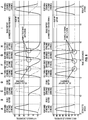
- Fig. 8 is a graphical depiction of hip joint component angle versus time across different gait stages for both the right hip joint and left hip joint of the exoskeleton device, and a corresponding graphical depiction of knee joint component angle versus time across such different gait stages for the right knee joint and left knee joint of the exoskeleton device.
- Panels A-J correspond to different gait stages. For purposes of illustration, a subject starts in a standard gait mode with the left leg in stance state and the right leg in swing state, and thus the angles of the hip and knee joints alter as shown in Panel A as the right leg swings.
- the subject follows the swing state of the right leg of Panel A with a static double support state as shown in Panel B, during which the hip and knee joint angles are constant as motion comes to a stop.
- Panels C and D show similar gait characteristics of the standard gait control with the right leg now in the stance state in the left leg now in swing state (Panel C) followed by another static double support stance state (Panel D).
- Panel E then is comparable to Panel A illustrating the next step, which is the next gait cycle in which the left leg again is in the stance state with the right leg in the swing state.
- the standard gait control is characterized by significant time spent in the static double support states of Panels B and D during which the joint angle velocities are zero.
- the transition from Panel E to Panel F corresponds to transitioning from standard gait control to advanced gait control.
- an angular position of the stance/trailing leg is sensed and measured during the dynamic single support states to determine whether advanced gait will occur during the following step, e.g., corresponding to Panel E the angle of the left leg, as the stance/trailing leg, is sensed and measured during a right step (right leg swing) to determine if advanced gait should occur during the subsequent left step.
- Advanced gait control is enabled if the angular position of the stance/trailing leg surpasses the advanced gait threshold, and an advanced gait step occurs immediately following the observed step.
- Panels F, G, and H of Fig. 8 illustrate advanced gait control steps.
- a swing to stance hip joint extension i.e., the hip joint component of the exoskeleton device extends as the corresponding leg transitions from the swing state to the stance state.
- the hip joint component experiences a continuous velocity through the heel strike.
- a stance to swing knee joint flexion i.e., the knee joint component of the exoskeleton device flexes as the corresponding leg transitions from the stance state to the swing state.
- the knee joint flexes early in the swing state, or in other words, essentially the knee begins bending toward the end of stance state to get a better "push off” in the step at the initiation of the swing state.
- the result of the advanced gait control is a more continuous stepping motion, which significantly reduces or eliminates the double support static states experienced in the standard gait control steps as shown in Panels B and D.
- Panels I and J demonstrate a transition back from the advanced gait control to standard gait control.
- the angle measurements have transitioned to a state in which the advanced gait threshold is no longer satisfied.
- the system returns to the double support static state in preparation to resume walking in accordance with standard gait control, with a standard gait step being taken as depicted in Panel J.
- the system optimizes user contribution to stepping versus contribution by the exoskeleton device. For users who are not wholly disabled, adjusting the user contribution to require more or less effort can help the user train with the device, and improve overall strength and performance. To achieve such control, the exoskeleton joint components are back drivable to accommodate force applied by the user's own efforts to walk.
- step length may be tied to step speed, giving the user the ability to speed and slow the gait as desired.
- a user can by choice switch between standard gait control and advanced gait control. For example, a user can perform with the exoskeleton device to satisfy the advanced gait threshold, thereby entering advanced gait control from standard gait control.
- the user can hold the stance/trailing leg in place to resume a double support stance, which then triggers the system to transition back to standard gait control.
- Such transition is depicted, for example, in the extended double support static state of Panel I of Fig. 8 , after which the standard gait control is resumed.
- Another feature of advanced gait control is an automated speed boost feature.
- One exemplary device setting related to such feature is a "Speed Boost Level” feature, which automatically increases step speed while performing in the advanced gait mode.
- a “high” setting will increase step speed by a full increment (i.e. “medium” speed steps in standard gait will become fast speed steps in advanced gait).
- the “low” setting will increase step speed by a half increment (i.e. "low” speed steps in standard gait will become “medium-low” speed steps in advanced gait).
- Another exemplary device setting for automated speed boost is a “Speed Boost Onset” feature, which determines how the speed boost will occur. With a “gradual” onset setting, the speed boost level occurs incrementally, over the course of a few advanced gait steps. With an “immediate” onset setting, the speed boost level will occur immediately, with the first advanced gait step.
- an aspect of the invention is a control method for a mobility assistance device employing advanced gait control, as defined in the appended claims.
- the control method employs the following steps: providing said mobility device including a control system for controlling operation of the mobility device components to selectively configure and modulate hip and knee joint components to perform a gait cycle; providing within said mobility device a control application to be executed by the control system to control the gait cycle; and providing within said mobility device a plurality of sensors to detect a state of the hip and knee joint components to determine an angular position of the right leg and left leg during the gait cycle.
- the control system executes the control application to perform the steps of: sensing at least one of an angular position or angular velocity of a stance/trailing leg during a single support dynamic state of the gait cycle; determining whether the angular position or angular velocity satisfies an advanced gait threshold; and when it is determined that the angular position or angular velocity satisfies the advanced gait threshold, the control system employs advanced gait control of the hip and knee joint components by which a duration of double support states between single support dynamic states is minimized.
- control system further controls the hip joint components to utilize advanced gait joint trajectories in which hip joint component velocities are non-zero for the hip joint components during transitions from swing states to stance states of the gait cycle, and in which knee joint component velocities are non-zero for the knee joint components during transitions from stance states to swing states of the gait cycle.
- control system controls the knee and hip joint components such that each step of the gait cycle blends into a next step by way of hip joint component swing-to-stance extension and/or knee joint component stance-to-swing flexion, and at least one joint component is always moving during the gait cycle.
- the control system When it is determined that the angular position and angular velocity do not satisfy the advanced gait threshold, the control system employs standard gait control in which double support states are maintained between single support dynamic states, and a decision whether to step is made by sensing an angular position of the forward leg during the double support states.
Landscapes
- Health & Medical Sciences (AREA)
- Engineering & Computer Science (AREA)
- General Health & Medical Sciences (AREA)
- Public Health (AREA)
- Epidemiology (AREA)
- Biomedical Technology (AREA)
- Life Sciences & Earth Sciences (AREA)
- Animal Behavior & Ethology (AREA)
- Veterinary Medicine (AREA)
- Physical Education & Sports Medicine (AREA)
- Rehabilitation Therapy (AREA)
- Pain & Pain Management (AREA)
- Medical Informatics (AREA)
- Primary Health Care (AREA)
- General Business, Economics & Management (AREA)
- Business, Economics & Management (AREA)
- Robotics (AREA)
- Mechanical Engineering (AREA)
- Automation & Control Theory (AREA)
- General Physics & Mathematics (AREA)
- Human Computer Interaction (AREA)
- Orthopedic Medicine & Surgery (AREA)
- Physics & Mathematics (AREA)
- Oral & Maxillofacial Surgery (AREA)
- Surgery (AREA)
- Cardiology (AREA)
- Vascular Medicine (AREA)
- Heart & Thoracic Surgery (AREA)
- Transplantation (AREA)
- Urology & Nephrology (AREA)
- Nuclear Medicine, Radiotherapy & Molecular Imaging (AREA)
- Biophysics (AREA)
- Rehabilitation Tools (AREA)
- Manipulator (AREA)
Claims (15)
- Procédé de commande pour commander un dispositif de mobilité (100) ayant une pluralité de composants de dispositif de mobilité comprenant un composant d'articulation de la hanche droite (102R) et un composant d'articulation du genou droit (104R) correspondant à une jambe droite, et un composant d'articulation de la hanche gauche (102L) et un composant d'articulation du genou gauche (104L) correspondant à une jambe gauche, le procédé de commande comprenant les étapes de :fourniture dudit dispositif de mobilité (100), ledit dispositif de mobilité comprenant en outre un système de commande (20) pour commander le fonctionnement des composants de dispositif de mobilité pour configurer et moduler sélectivement les composants d'articulations de la hanche (102R, 102L) et du genou (104R, 104L) pour effectuer un cycle de marche ;fourniture, dans ledit dispositif de mobilité, d'une application de commande (26) à exécuter par le système de commande (20) pour commander le cycle de marche ;fourniture, dans ledit dispositif de mobilité, d'une pluralité de capteurs (36) pour détecter un état des composants d'articulations de la hanche (102R, 102L) et du genou (104R, 104L) afin de déterminer une position angulaire de la jambe droite et de la jambe gauche pendant le cycle de marche ; etexécution de l'application de commande (26) avec le système de commande (20) pour effectuer en outre les étapes :détection de l'au moins une d'une position angulaire ou d'une vitesse angulaire d'une jambe d'appui pendant la marche au cours d'un état dynamique d'appui unique du cycle de marche comprenant un état de marche dans lequel une jambe se balance tandis que la jambe opposée est la jambe d'appui pendant la marche ;détermination pour savoir si la position angulaire ou la vitesse angulaire satisfait à un seuil de marche avancée ; etlorsqu'il est déterminé que la position angulaire ou la vitesse angulaire satisfait au seuil de marche avancée, le système de commande (20) utilise une commande de marche avancée des composants d'articulations de la hanche et du genou moyennant quoi une détermination pour initier la marche est effectuée au cours d'un état dynamique d'appui unique précédent comprenant un état de marche dans lequel une jambe se balance tandis que la jambe opposée est la jambe d'appui pendant la marche, initiant ainsi un mouvement de marche dans lequel des pas sont faits sensiblement en succession immédiate pour minimiser une durée d'états de double appui dans lesquels les deux jambes sont en appui entre les états dynamiques d'appui unique.
- Procédé de commande selon la revendication 1, dans lequel, pour une commande de marche avancée, le système de commande (20) commande les composants d'articulation de la hanche (102R, 102L) pour utiliser des trajectoires d'articulation de marche avancée dans lesquelles les vitesses de composant d'articulation de la hanche sont non nulles pour les composants d'articulation de la hanche (102R, 102L) pendant les transitions des états de balancement aux états d'appui du cycle de marche ; et/ou
dans lequel, pour une commande de marche avancée, le système de commande (20) commande les composants d'articulation du genou (104R, 104L) pour utiliser des trajectoires d'articulation de marche avancée dans lesquelles les vitesses de composant d'articulation du genou sont non nulles pour les composants d'articulation du genou (104R, 104L) pendant les transitions des états d'appui aux états de balancement du cycle de marche. - Procédé de commande selon la revendication 2, dans lequel, lorsqu'une trajectoire de marche avancée est utilisée pendant le balancement de composant d'articulation de la hanche, le système de commande (20) utilise une trajectoire de marche avancée dans un appui ultérieur de composant d'articulation de la hanche ; et/ou
dans lequel, lorsqu'une trajectoire de marche avancée est utilisée pendant un appui de composant d'articulation du genou, le système de commande (20) utilise une trajectoire de marche avancée dans un balancement ultérieur de composant d'articulation du genou. - Procédé de commande selon l'une quelconque des revendications 1 à 3, dans lequel, pour une commande de marche avancée, le système de commande (20) commande les composants d'articulations du genou (104R, 104L) et de la hanche (102R, 102L) de sorte que chaque pas du cycle de marche se produise en succession sensiblement immédiate après un pas précédent par extension du balancement à l'appui de composant d'articulation de la hanche, et/ou flexion de l'appui au balancement de composant d'articulation du genou.
- Procédé de commande selon l'une quelconque des revendications 1 à 4, dans lequel la position angulaire est mesurée d'une jambe d'appui gauche pendant la marche au cours d'un état dynamique d'appui unique du cycle de marche pour déterminer s'il faut faire un pas avec la jambe droite, et la position angulaire est mesurée d'une jambe d'appui droite pendant la marche au cours d'un état dynamique d'appui unique du cycle de marche pour déterminer s'il faut faire un pas avec la jambe gauche.
- Procédé de commande selon l'une quelconque des revendications 1 à 5, dans lequel, lorsqu'il est déterminé que la condition de seuil de marche avancée n'est pas satisfaite, le système de commande (20) utilise une commande de marche standard dans laquelle des états de double appui sont maintenus entre des états dynamiques d'appui unique, et une décision de faire un pas est prise en détectant une position angulaire de la jambe avant au cours de l'état de double appui.
- Support non transitoire lisible par ordinateur (30, 24) stockant un code de programme pour une application de commande (26) pour une utilisation dans la commande d'un dispositif de mobilité ayant une pluralité de composants de dispositif de mobilité comprenant un composant d'articulation de la hanche droite et un composant d'articulation du genou droit correspondant à une jambe droite, et un composant d'articulation de la hanche gauche et un composant d'articulation du genou gauche correspondant à une jambe gauche, le dispositif de mobilité comportant au moins un composant d'entraînement (34) qui entraîne au moins un composant d'articulation ;dans lequel le dispositif de mobilité (100) comprend : un système de commande électronique (20) pour commander le fonctionnement de l'au moins un composant d'entraînement pour configurer et moduler sélectivement l'au moins un composant d'articulation, et une pluralité de capteurs (36) pour détecter un état de l'au moins un composant d'entraînement et/ou de l'au moins un composant d'articulation ; etle code de programme, lorsqu'il est exécuté par le système de commande électronique (20) effectue les étapes de :fourniture dudit dispositif de mobilité, ledit dispositif de mobilité comprenant en outre le système de commande (20) pour commander le fonctionnement des composants de dispositif de mobilité pour configurer et moduler sélectivement les composants d'articulations de la hanche (102R, 102L) et du genou (104R, 104L) pour effectuer un cycle de marche ;fourniture, dans ledit dispositif de mobilité, d'une application de commande (26) à exécuter par le système de commande (20) pour commander le cycle de marche ;fourniture, dans ledit dispositif de mobilité, d'une pluralité de capteurs (36) pour détecter un état des composants d'articulations de la hanche (102R, 102L) et du genou (104R, 104L) afin de déterminer une position angulaire de la jambe droite et de la jambe gauche pendant le cycle de marche ; etexécution de l'application de commande (26) avec le système de commande (20) pour effectuer en outre les étapes :de détection d'au moins l'une d'une position angulaire ou d'une vitesse angulaire d'une jambe d'appui pendant la marche au cours d'un état dynamique d'appui unique du cycle de marche comprenant un état de marche dans lequel une jambe se balance tandis que la jambe opposée est la jambe d'appui pendant la marche ;de détermination pour savoir si la position angulaire ou la vitesse angulaire satisfait à un seuil de marche avancée ; etlorsqu'il est déterminé que la position angulaire ou la vitesse angulaire satisfait au seuil de marche avancée, le système de commande utilise une commande de marche avancée des composants d'articulations de la hanche (102R, 102L) et du genou (104R, 104L) moyennant quoi une détermination pour initier la marche est effectuée au cours d'un état dynamique d'appui unique précédent comprenant un état de marche dans lequel une jambe se balance tandis que la jambe opposée est la jambe d'appui pendant la marche, initiant ainsi un mouvement de marche dans lequel des pas sont faits sensiblement en succession immédiate pour minimiser une durée d'états de double appui dans lesquels les deux jambes sont en appui entre les états dynamiques d'appui unique.
- Support non transitoire lisible par ordinateur selon la revendication 7, dans lequel, pour une commande de marche avancée, le système de commande (20) exécute le code de programme pour commander les composants d'articulation de la hanche (102R, 102L) pour utiliser des trajectoires d'articulation de marche avancée dans lesquelles les vitesses de composant d'articulation de la hanche sont non nulles pour les composants d'articulation de la hanche pendant les transitions des états de balancement aux états d'appui du cycle de marche ; et/ou
dans lequel, pour une commande de marche avancée, le système de commande (20) exécute le code de programme pour commander les composants d'articulation du genou (104R, 104L) pour utiliser des trajectoires d'articulation de marche avancée dans lesquelles les vitesses de composant d'articulation du genou sont non nulles pour les composants d'articulation du genou pendant les transitions des états d'appui aux états de balancement du cycle de marche. - Support non transitoire lisible par ordinateur selon la revendication 8, dans lequel, lorsqu'une trajectoire de marche avancée est utilisée pendant le balancement de composant d'articulation de la hanche, le système de commande (20) exécute le code de programme pour utiliser une trajectoire de marche avancée dans un appui ultérieur de composant d'articulation de la hanche ; et/ou
dans lequel, lorsqu'une trajectoire de marche avancée est utilisée pendant un appui de composant d'articulation du genou, le système de commande (20) exécute le code de programme pour utiliser une trajectoire de marche avancée dans un balancement ultérieur de composant d'articulation du genou. - Support non transitoire lisible par ordinateur selon l'une quelconque des revendications 7 à 9, dans lequel, pour une commande de marche avancée, le système de commande (20) exécute le code de programme pour commander les composants d'articulations du genou (104R, 104L) et de la hanche (102R, 102L) de sorte que chaque pas du cycle de marche se produise en succession sensiblement immédiate après un pas précédent par extension du balancement à l'appui de composant d'articulation de la hanche, et/ou flexion de l'appui au balancement de composant d'articulation du genou.
- Support non transitoire lisible par ordinateur selon l'une quelconque des revendications 7 à 10, dans lequel la position angulaire est mesurée d'une jambe d'appui gauche/arrière au cours d'un état dynamique d'appui unique du cycle de marche pour déterminer s'il faut faire un pas avec la jambe droite, et la position angulaire est mesurée d'une jambe d'appui droite/arrière au cours d'un état dynamique d'appui unique du cycle de marche pour déterminer s'il faut faire un pas avec la jambe gauche.
- Support non transitoire lisible par ordinateur selon l'une quelconque des revendications 7 à 11, dans lequel la position angulaire de la jambe d'appui pendant la marche est détectée entre l'appui intermédiaire et l'appui terminal de ladite jambe d'appui pendant la marche.
- Support non transitoire lisible par ordinateur selon l'une quelconque des revendications 7 à 12, dans lequel, lorsqu'il est déterminé que la condition de seuil de marche avancée n'est pas satisfaite, le système de commande (20) exécute le code de programme pour utiliser une commande de marche standard dans laquelle des états de double appui sont maintenus entre des états dynamiques d'appui unique, et une décision de faire un pas est prise en détectant une position angulaire de la jambe avant au cours de l'état de double appui.
- Dispositif de mobilité ayant une pluralité de composants de dispositif de mobilité comprenant un composant d'articulation de la hanche droite et un composant d'articulation du genou droit correspondant à une jambe droite, et un composant d'articulation de la hanche gauche et un composant d'articulation du genou gauche correspondant à une jambe gauche, comprenant :un système de commande électronique (20) pour commander le fonctionnement d'au moins un composant d'entraînement (34) pour configurer et moduler sélectivement au moins un composant d'articulation ;une pluralité de capteurs (36) pour détecter un état de l'au moins un composant d'entraînement et/ou de l'au moins un composant d'articulation ; etle support non transitoire lisible par ordinateur (30, 24) selon l'une des revendications 7 à 13, dans lequel le système de commande électronique (20) exécute le code de programme stocké sur le support non transitoire lisible par ordinateur (30, 24).
- Dispositif de mobilité selon la revendication 14, dans lequel :le dispositif de mobilité est un dispositif d'exosquelette de mobilité à jambes (100) comprenant une pluralité de composants d'entraînement (34) qui entraînent une pluralité de composants d'articulation comprenant au moins des composants d'articulation du genou (104R, 104L) et des composants d'articulation de la hanche (102R, 102L) ; oule dispositif de mobilité est un dispositif orthétique comprenant l'au moins un composant d'entraînement (34) qui entraîne l'au moins un composant d'articulation ; oule dispositif de mobilité est un dispositif prothétique comprenant l'au moins un composant d'entraînement (34) qui entraîne l'au moins un composant d'articulation.
Applications Claiming Priority (2)
| Application Number | Priority Date | Filing Date | Title |
|---|---|---|---|
| US201862627867P | 2018-02-08 | 2018-02-08 | |
| PCT/US2018/028787 WO2019156698A1 (fr) | 2018-02-08 | 2018-04-23 | Système de commande de marche avancée et procédés permettant un mouvement de marche continu d'un dispositif d'exosquelette motorisé |
Publications (2)
| Publication Number | Publication Date |
|---|---|
| EP3750166A1 EP3750166A1 (fr) | 2020-12-16 |
| EP3750166B1 true EP3750166B1 (fr) | 2022-01-05 |
Family
ID=62148484
Family Applications (1)
| Application Number | Title | Priority Date | Filing Date |
|---|---|---|---|
| EP18724037.9A Active EP3750166B1 (fr) | 2018-02-08 | 2018-04-23 | Système de commande de marche avancée et procédés permettant un mouvement de marche continu d'un dispositif d'exosquelette motorisé |
Country Status (4)
| Country | Link |
|---|---|
| US (1) | US11679056B2 (fr) |
| EP (1) | EP3750166B1 (fr) |
| ES (1) | ES2907244T3 (fr) |
| WO (1) | WO2019156698A1 (fr) |
Families Citing this family (12)
| Publication number | Priority date | Publication date | Assignee | Title |
|---|---|---|---|---|
| KR102748430B1 (ko) * | 2019-10-28 | 2025-01-03 | 삼성전자주식회사 | 운동 보조 방법 및 운동 보조 장치 |
| KR102833373B1 (ko) * | 2019-10-28 | 2025-07-11 | 삼성전자주식회사 | 착용형 장치 및 이의 동작 방법 |
| CN111481405A (zh) * | 2020-04-22 | 2020-08-04 | 北京海益同展信息科技有限公司 | 一种运动指令的触发方法、装置和外骨骼设备 |
| US11853034B2 (en) * | 2020-05-08 | 2023-12-26 | Skip Innovations, Inc. | Exosuit activity transition control |
| CN112472530B (zh) * | 2020-12-01 | 2023-02-03 | 天津理工大学 | 一种基于步行比趋势变化的奖励函数建立方法 |
| CN113059549B (zh) * | 2021-03-17 | 2022-04-26 | 深圳因特安全技术有限公司 | 一种消防救援可穿戴助力外骨骼机器人 |
| CN113208583B (zh) * | 2021-04-12 | 2022-05-27 | 华南理工大学 | 外骨骼辅助下的步态识别方法、介质和设备 |
| CN114750133B (zh) * | 2022-04-20 | 2023-12-26 | 中国科学院深圳先进技术研究院 | 一种腰部外骨骼机器人系统及其助力控制方法 |
| USD1010141S1 (en) * | 2022-06-08 | 2024-01-02 | Wandercraft | Exoskeleton walking aid |
| CN116530972A (zh) * | 2023-03-24 | 2023-08-04 | 南京伟思医疗科技股份有限公司 | 一种外骨骼机器人多模式行走机制下的痉挛异常监测器 |
| CN119811586B (zh) * | 2025-03-14 | 2025-05-30 | 中科南京人工智能创新研究院 | 基于频域学习的步态康复具身机器人时序数据建模优化方法 |
| CN120645235B (zh) * | 2025-08-19 | 2025-12-26 | 杭州智元研究院有限公司 | 一种外骨骼机器人下肢绑缚状态的实时检测方法及系统 |
Family Cites Families (18)
| Publication number | Priority date | Publication date | Assignee | Title |
|---|---|---|---|---|
| US8834169B2 (en) | 2005-08-31 | 2014-09-16 | The Regents Of The University Of California | Method and apparatus for automating arm and grasping movement training for rehabilitation of patients with motor impairment |
| US7578799B2 (en) * | 2006-06-30 | 2009-08-25 | Ossur Hf | Intelligent orthosis |
| WO2008066856A2 (fr) | 2006-11-27 | 2008-06-05 | Northeastern University | Dispositif orthétique pour cheville adapté spécifiquement au patient |
| US8795207B2 (en) | 2008-05-23 | 2014-08-05 | Fundacion Fatronik | Portable device for upper limb rehabilitation |
| EP2346447B1 (fr) * | 2008-07-23 | 2019-09-04 | Ekso Bionics, Inc. | Exosquelette et procédé de maîtrise du balancement de la jambe de l'exosquelette |
| US8096965B2 (en) | 2008-10-13 | 2012-01-17 | Argo Medical Technologies Ltd. | Locomotion assisting device and method |
| WO2010088262A2 (fr) | 2009-01-27 | 2010-08-05 | University Of Washington | Système de surveillance d'un membre prothétique |
| WO2011002306A1 (fr) * | 2009-07-01 | 2011-01-06 | Rex Bionics Limited | Système de commande daide à la mobilité |
| WO2012048123A1 (fr) * | 2010-10-06 | 2012-04-12 | Berkeley Bionics | Interfaces homme-machine pour appareillage des extrémités inférieures |
| AU2013235009A1 (en) | 2012-03-22 | 2014-09-25 | Ekso Bionics, Inc. | Human machine interface for lower extremity orthotics |
| US9566705B2 (en) * | 2012-06-15 | 2017-02-14 | Vanderbilt University | Movement assistance device |
| US10406059B2 (en) * | 2014-04-21 | 2019-09-10 | The Trustees Of Columbia University In The City Of New York | Human movement research, therapeutic, and diagnostic devices, methods, and systems |
| JP6878271B2 (ja) * | 2014-09-19 | 2021-05-26 | プレジデント アンド フェローズ オブ ハーバード カレッジ | 人の運動を補助するためのソフトエクソスーツ |
| EP3328277A4 (fr) | 2015-07-31 | 2019-03-06 | Cala Health, Inc. | Systèmes, dispositifs et procédé permettant le traitement de l'arthrose |
| KR102482436B1 (ko) * | 2015-09-02 | 2022-12-28 | 삼성전자주식회사 | 보행 보조 장치 및 그 동작 방법 |
| TWI564129B (zh) | 2015-11-27 | 2017-01-01 | 財團法人工業技術研究院 | 行動輔助機器人之姿態估測方法 |
| KR102510874B1 (ko) * | 2017-06-15 | 2023-03-16 | 삼성전자주식회사 | 보행 보조 방법 및 이를 수행하는 장치들 |
| US20190160321A1 (en) * | 2017-11-30 | 2019-05-30 | Steering Solutions Ip Holding Corporation | Assist profiling and dynamic torque generation for biomechanical assistive device |
-
2018
- 2018-04-23 ES ES18724037T patent/ES2907244T3/es active Active
- 2018-04-23 US US16/761,928 patent/US11679056B2/en active Active
- 2018-04-23 EP EP18724037.9A patent/EP3750166B1/fr active Active
- 2018-04-23 WO PCT/US2018/028787 patent/WO2019156698A1/fr not_active Ceased
Also Published As
| Publication number | Publication date |
|---|---|
| EP3750166A1 (fr) | 2020-12-16 |
| ES2907244T3 (es) | 2022-04-22 |
| WO2019156698A1 (fr) | 2019-08-15 |
| US20200323726A1 (en) | 2020-10-15 |
| US11679056B2 (en) | 2023-06-20 |
Similar Documents
| Publication | Publication Date | Title |
|---|---|---|
| EP3750166B1 (fr) | Système de commande de marche avancée et procédés permettant un mouvement de marche continu d'un dispositif d'exosquelette motorisé | |
| US10390973B2 (en) | Interactive exoskeleton robotic knee system | |
| EP3225363B1 (fr) | Exosquelette pour assister les mouvements humains | |
| US10792210B2 (en) | Movement assistance device | |
| CN112370305B (zh) | 一种下肢康复训练外骨骼机器人 | |
| EP2621416B1 (fr) | Dispositif d'assistance au mouvement | |
| EP3317053B1 (fr) | Système de contrôle et de commande de sécurité pour un dispositif d'exosquelette à mobilité à jambes | |
| KR102503955B1 (ko) | 밸런스 제어 방법 및 장치 | |
| CA2828420C (fr) | Dispositif et systeme d'entrainement a la marche | |
| US7346396B2 (en) | Interface to FES control system | |
| KR101913187B1 (ko) | 편마비 환자용 보행 보조장치 및 그 제어방법 | |
| EP3377278B1 (fr) | Procédés d'atténuation de chute et de récupération pour un dispositif d'exosquelette de mobilité sur jambes | |
| KR101302364B1 (ko) | 하지보조기용 보행감각 인지장치 | |
| JP2005000500A (ja) | 足関節電動装具 | |
| KR100802533B1 (ko) | 인체 하지의 보행모드 결정장치 및 이를 갖는 인체 하지용보조 근력 로봇 및 이를 사용한 인체 하지의 보행모드결정방법 | |
| JP2002301124A (ja) | 歩行補助装置 | |
| WO2016180074A1 (fr) | Système de genou robotique à exosquelette interactif | |
| IL303545A (en) | An activated exoskeleton system in the knee | |
| WO2022197280A1 (fr) | Procédé de commande d'une orthèse de pied-cheville-genou motorisée | |
| CN113230094A (zh) | 一种单腿外骨骼机器人及其控制方法 | |
| CN117224367A (zh) | 一种基于传感器映射的下肢外骨骼康复训练系统 | |
| KR102893991B1 (ko) | 하지 재활 훈련 로봇 시스템 및 이의 제어 방법 | |
| WO2022231566A1 (fr) | Procédé de commande d'une orthèse motorisée de genou-cheville-pied |
Legal Events
| Date | Code | Title | Description |
|---|---|---|---|
| STAA | Information on the status of an ep patent application or granted ep patent |
Free format text: STATUS: UNKNOWN |
|
| STAA | Information on the status of an ep patent application or granted ep patent |
Free format text: STATUS: THE INTERNATIONAL PUBLICATION HAS BEEN MADE |
|
| PUAI | Public reference made under article 153(3) epc to a published international application that has entered the european phase |
Free format text: ORIGINAL CODE: 0009012 |
|
| STAA | Information on the status of an ep patent application or granted ep patent |
Free format text: STATUS: REQUEST FOR EXAMINATION WAS MADE |
|
| 17P | Request for examination filed |
Effective date: 20200521 |
|
| AK | Designated contracting states |
Kind code of ref document: A1 Designated state(s): AL AT BE BG CH CY CZ DE DK EE ES FI FR GB GR HR HU IE IS IT LI LT LU LV MC MK MT NL NO PL PT RO RS SE SI SK SM TR |
|
| AX | Request for extension of the european patent |
Extension state: BA ME |
|
| DAV | Request for validation of the european patent (deleted) | ||
| DAX | Request for extension of the european patent (deleted) | ||
| GRAP | Despatch of communication of intention to grant a patent |
Free format text: ORIGINAL CODE: EPIDOSNIGR1 |
|
| STAA | Information on the status of an ep patent application or granted ep patent |
Free format text: STATUS: GRANT OF PATENT IS INTENDED |
|
| RIC1 | Information provided on ipc code assigned before grant |
Ipc: B25J 9/00 20060101ALI20210913BHEP Ipc: A61H 3/00 20060101ALI20210913BHEP Ipc: A61H 1/02 20060101ALI20210913BHEP Ipc: A61F 2/70 20060101ALI20210913BHEP Ipc: G16H 20/40 20180101ALI20210913BHEP Ipc: G16H 20/30 20180101ALI20210913BHEP Ipc: G16H 40/63 20180101AFI20210913BHEP |
|
| INTG | Intention to grant announced |
Effective date: 20211001 |
|
| GRAS | Grant fee paid |
Free format text: ORIGINAL CODE: EPIDOSNIGR3 |
|
| GRAA | (expected) grant |
Free format text: ORIGINAL CODE: 0009210 |
|
| STAA | Information on the status of an ep patent application or granted ep patent |
Free format text: STATUS: THE PATENT HAS BEEN GRANTED |
|
| AK | Designated contracting states |
Kind code of ref document: B1 Designated state(s): AL AT BE BG CH CY CZ DE DK EE ES FI FR GB GR HR HU IE IS IT LI LT LU LV MC MK MT NL NO PL PT RO RS SE SI SK SM TR |
|
| REG | Reference to a national code |
Ref country code: GB Ref legal event code: FG4D |
|
| REG | Reference to a national code |
Ref country code: CH Ref legal event code: EP |
|
| REG | Reference to a national code |
Ref country code: AT Ref legal event code: REF Ref document number: 1461287 Country of ref document: AT Kind code of ref document: T Effective date: 20220115 |
|
| REG | Reference to a national code |
Ref country code: DE Ref legal event code: R096 Ref document number: 602018029109 Country of ref document: DE |
|
| REG | Reference to a national code |
Ref country code: IE Ref legal event code: FG4D |
|
| REG | Reference to a national code |
Ref country code: ES Ref legal event code: FG2A Ref document number: 2907244 Country of ref document: ES Kind code of ref document: T3 Effective date: 20220422 |
|
| REG | Reference to a national code |
Ref country code: LT Ref legal event code: MG9D |
|
| REG | Reference to a national code |
Ref country code: NL Ref legal event code: MP Effective date: 20220105 |
|
| REG | Reference to a national code |
Ref country code: AT Ref legal event code: MK05 Ref document number: 1461287 Country of ref document: AT Kind code of ref document: T Effective date: 20220105 |
|
| PG25 | Lapsed in a contracting state [announced via postgrant information from national office to epo] |
Ref country code: NL Free format text: LAPSE BECAUSE OF FAILURE TO SUBMIT A TRANSLATION OF THE DESCRIPTION OR TO PAY THE FEE WITHIN THE PRESCRIBED TIME-LIMIT Effective date: 20220105 |
|
| PG25 | Lapsed in a contracting state [announced via postgrant information from national office to epo] |
Ref country code: SE Free format text: LAPSE BECAUSE OF FAILURE TO SUBMIT A TRANSLATION OF THE DESCRIPTION OR TO PAY THE FEE WITHIN THE PRESCRIBED TIME-LIMIT Effective date: 20220105 Ref country code: RS Free format text: LAPSE BECAUSE OF FAILURE TO SUBMIT A TRANSLATION OF THE DESCRIPTION OR TO PAY THE FEE WITHIN THE PRESCRIBED TIME-LIMIT Effective date: 20220105 Ref country code: PT Free format text: LAPSE BECAUSE OF FAILURE TO SUBMIT A TRANSLATION OF THE DESCRIPTION OR TO PAY THE FEE WITHIN THE PRESCRIBED TIME-LIMIT Effective date: 20220505 Ref country code: NO Free format text: LAPSE BECAUSE OF FAILURE TO SUBMIT A TRANSLATION OF THE DESCRIPTION OR TO PAY THE FEE WITHIN THE PRESCRIBED TIME-LIMIT Effective date: 20220405 Ref country code: LT Free format text: LAPSE BECAUSE OF FAILURE TO SUBMIT A TRANSLATION OF THE DESCRIPTION OR TO PAY THE FEE WITHIN THE PRESCRIBED TIME-LIMIT Effective date: 20220105 Ref country code: HR Free format text: LAPSE BECAUSE OF FAILURE TO SUBMIT A TRANSLATION OF THE DESCRIPTION OR TO PAY THE FEE WITHIN THE PRESCRIBED TIME-LIMIT Effective date: 20220105 Ref country code: BG Free format text: LAPSE BECAUSE OF FAILURE TO SUBMIT A TRANSLATION OF THE DESCRIPTION OR TO PAY THE FEE WITHIN THE PRESCRIBED TIME-LIMIT Effective date: 20220405 |
|
| PGFP | Annual fee paid to national office [announced via postgrant information from national office to epo] |
Ref country code: IT Payment date: 20220421 Year of fee payment: 5 Ref country code: ES Payment date: 20220503 Year of fee payment: 5 |
|
| PG25 | Lapsed in a contracting state [announced via postgrant information from national office to epo] |
Ref country code: PL Free format text: LAPSE BECAUSE OF FAILURE TO SUBMIT A TRANSLATION OF THE DESCRIPTION OR TO PAY THE FEE WITHIN THE PRESCRIBED TIME-LIMIT Effective date: 20220105 Ref country code: LV Free format text: LAPSE BECAUSE OF FAILURE TO SUBMIT A TRANSLATION OF THE DESCRIPTION OR TO PAY THE FEE WITHIN THE PRESCRIBED TIME-LIMIT Effective date: 20220105 Ref country code: GR Free format text: LAPSE BECAUSE OF FAILURE TO SUBMIT A TRANSLATION OF THE DESCRIPTION OR TO PAY THE FEE WITHIN THE PRESCRIBED TIME-LIMIT Effective date: 20220406 Ref country code: FI Free format text: LAPSE BECAUSE OF FAILURE TO SUBMIT A TRANSLATION OF THE DESCRIPTION OR TO PAY THE FEE WITHIN THE PRESCRIBED TIME-LIMIT Effective date: 20220105 Ref country code: AT Free format text: LAPSE BECAUSE OF FAILURE TO SUBMIT A TRANSLATION OF THE DESCRIPTION OR TO PAY THE FEE WITHIN THE PRESCRIBED TIME-LIMIT Effective date: 20220105 |
|
| PG25 | Lapsed in a contracting state [announced via postgrant information from national office to epo] |
Ref country code: IS Free format text: LAPSE BECAUSE OF FAILURE TO SUBMIT A TRANSLATION OF THE DESCRIPTION OR TO PAY THE FEE WITHIN THE PRESCRIBED TIME-LIMIT Effective date: 20220505 |
|
| REG | Reference to a national code |
Ref country code: DE Ref legal event code: R097 Ref document number: 602018029109 Country of ref document: DE |
|
| PG25 | Lapsed in a contracting state [announced via postgrant information from national office to epo] |
Ref country code: SM Free format text: LAPSE BECAUSE OF FAILURE TO SUBMIT A TRANSLATION OF THE DESCRIPTION OR TO PAY THE FEE WITHIN THE PRESCRIBED TIME-LIMIT Effective date: 20220105 Ref country code: SK Free format text: LAPSE BECAUSE OF FAILURE TO SUBMIT A TRANSLATION OF THE DESCRIPTION OR TO PAY THE FEE WITHIN THE PRESCRIBED TIME-LIMIT Effective date: 20220105 Ref country code: RO Free format text: LAPSE BECAUSE OF FAILURE TO SUBMIT A TRANSLATION OF THE DESCRIPTION OR TO PAY THE FEE WITHIN THE PRESCRIBED TIME-LIMIT Effective date: 20220105 Ref country code: EE Free format text: LAPSE BECAUSE OF FAILURE TO SUBMIT A TRANSLATION OF THE DESCRIPTION OR TO PAY THE FEE WITHIN THE PRESCRIBED TIME-LIMIT Effective date: 20220105 Ref country code: DK Free format text: LAPSE BECAUSE OF FAILURE TO SUBMIT A TRANSLATION OF THE DESCRIPTION OR TO PAY THE FEE WITHIN THE PRESCRIBED TIME-LIMIT Effective date: 20220105 Ref country code: CZ Free format text: LAPSE BECAUSE OF FAILURE TO SUBMIT A TRANSLATION OF THE DESCRIPTION OR TO PAY THE FEE WITHIN THE PRESCRIBED TIME-LIMIT Effective date: 20220105 |
|
| PLBE | No opposition filed within time limit |
Free format text: ORIGINAL CODE: 0009261 |
|
| STAA | Information on the status of an ep patent application or granted ep patent |
Free format text: STATUS: NO OPPOSITION FILED WITHIN TIME LIMIT |
|
| PG25 | Lapsed in a contracting state [announced via postgrant information from national office to epo] |
Ref country code: AL Free format text: LAPSE BECAUSE OF FAILURE TO SUBMIT A TRANSLATION OF THE DESCRIPTION OR TO PAY THE FEE WITHIN THE PRESCRIBED TIME-LIMIT Effective date: 20220105 |
|
| REG | Reference to a national code |
Ref country code: CH Ref legal event code: PL |
|
| 26N | No opposition filed |
Effective date: 20221006 |
|
| REG | Reference to a national code |
Ref country code: BE Ref legal event code: MM Effective date: 20220430 |
|
| PG25 | Lapsed in a contracting state [announced via postgrant information from national office to epo] |
Ref country code: MC Free format text: LAPSE BECAUSE OF FAILURE TO SUBMIT A TRANSLATION OF THE DESCRIPTION OR TO PAY THE FEE WITHIN THE PRESCRIBED TIME-LIMIT Effective date: 20220105 Ref country code: LU Free format text: LAPSE BECAUSE OF NON-PAYMENT OF DUE FEES Effective date: 20220423 Ref country code: LI Free format text: LAPSE BECAUSE OF NON-PAYMENT OF DUE FEES Effective date: 20220430 Ref country code: CH Free format text: LAPSE BECAUSE OF NON-PAYMENT OF DUE FEES Effective date: 20220430 |
|
| PG25 | Lapsed in a contracting state [announced via postgrant information from national office to epo] |
Ref country code: SI Free format text: LAPSE BECAUSE OF FAILURE TO SUBMIT A TRANSLATION OF THE DESCRIPTION OR TO PAY THE FEE WITHIN THE PRESCRIBED TIME-LIMIT Effective date: 20220105 Ref country code: BE Free format text: LAPSE BECAUSE OF NON-PAYMENT OF DUE FEES Effective date: 20220430 |
|
| PG25 | Lapsed in a contracting state [announced via postgrant information from national office to epo] |
Ref country code: IE Free format text: LAPSE BECAUSE OF NON-PAYMENT OF DUE FEES Effective date: 20220423 |
|
| PG25 | Lapsed in a contracting state [announced via postgrant information from national office to epo] |
Ref country code: MK Free format text: LAPSE BECAUSE OF FAILURE TO SUBMIT A TRANSLATION OF THE DESCRIPTION OR TO PAY THE FEE WITHIN THE PRESCRIBED TIME-LIMIT Effective date: 20220105 Ref country code: IT Free format text: LAPSE BECAUSE OF NON-PAYMENT OF DUE FEES Effective date: 20230423 Ref country code: CY Free format text: LAPSE BECAUSE OF FAILURE TO SUBMIT A TRANSLATION OF THE DESCRIPTION OR TO PAY THE FEE WITHIN THE PRESCRIBED TIME-LIMIT Effective date: 20220105 |
|
| REG | Reference to a national code |
Ref country code: ES Ref legal event code: FD2A Effective date: 20240529 |
|
| PG25 | Lapsed in a contracting state [announced via postgrant information from national office to epo] |
Ref country code: HU Free format text: LAPSE BECAUSE OF FAILURE TO SUBMIT A TRANSLATION OF THE DESCRIPTION OR TO PAY THE FEE WITHIN THE PRESCRIBED TIME-LIMIT; INVALID AB INITIO Effective date: 20180423 |
|
| PG25 | Lapsed in a contracting state [announced via postgrant information from national office to epo] |
Ref country code: ES Free format text: LAPSE BECAUSE OF NON-PAYMENT OF DUE FEES Effective date: 20230424 |
|
| PG25 | Lapsed in a contracting state [announced via postgrant information from national office to epo] |
Ref country code: ES Free format text: LAPSE BECAUSE OF NON-PAYMENT OF DUE FEES Effective date: 20230424 |
|
| PG25 | Lapsed in a contracting state [announced via postgrant information from national office to epo] |
Ref country code: MT Free format text: LAPSE BECAUSE OF FAILURE TO SUBMIT A TRANSLATION OF THE DESCRIPTION OR TO PAY THE FEE WITHIN THE PRESCRIBED TIME-LIMIT Effective date: 20220105 |
|
| REG | Reference to a national code |
Ref country code: GB Ref legal event code: 732E Free format text: REGISTERED BETWEEN 20241003 AND 20241009 |
|
| REG | Reference to a national code |
Ref country code: DE Ref legal event code: R082 Ref document number: 602018029109 Country of ref document: DE Representative=s name: MURGITROYD GERMANY PATENTANWALTSGESELLSCHAFT M, DE Ref country code: DE Ref legal event code: R081 Ref document number: 602018029109 Country of ref document: DE Owner name: EKSO BIONICS HOLDINGS, INC., SAN RAFAEL, US Free format text: FORMER OWNER: PARKER-HANNIFIN CORPORATION, CLEVELAND, OH, US |
|
| PGFP | Annual fee paid to national office [announced via postgrant information from national office to epo] |
Ref country code: DE Payment date: 20250423 Year of fee payment: 8 |
|
| PGFP | Annual fee paid to national office [announced via postgrant information from national office to epo] |
Ref country code: GB Payment date: 20250423 Year of fee payment: 8 |
|
| PGFP | Annual fee paid to national office [announced via postgrant information from national office to epo] |
Ref country code: FR Payment date: 20250423 Year of fee payment: 8 |
|
| PG25 | Lapsed in a contracting state [announced via postgrant information from national office to epo] |
Ref country code: TR Free format text: LAPSE BECAUSE OF FAILURE TO SUBMIT A TRANSLATION OF THE DESCRIPTION OR TO PAY THE FEE WITHIN THE PRESCRIBED TIME-LIMIT Effective date: 20220105 |