EP3750711A1 - Mécanisme d'encrage pour dispositif d'impression offset et machine d'impression - Google Patents
Mécanisme d'encrage pour dispositif d'impression offset et machine d'impression Download PDFInfo
- Publication number
- EP3750711A1 EP3750711A1 EP19850784.0A EP19850784A EP3750711A1 EP 3750711 A1 EP3750711 A1 EP 3750711A1 EP 19850784 A EP19850784 A EP 19850784A EP 3750711 A1 EP3750711 A1 EP 3750711A1
- Authority
- EP
- European Patent Office
- Prior art keywords
- roller
- shaft
- holder
- eccentric sleeve
- worm gear
- Prior art date
- Legal status (The legal status is an assumption and is not a legal conclusion. Google has not performed a legal analysis and makes no representation as to the accuracy of the status listed.)
- Granted
Links
Images


Classifications
-
- B—PERFORMING OPERATIONS; TRANSPORTING
- B41—PRINTING; LINING MACHINES; TYPEWRITERS; STAMPS
- B41F—PRINTING MACHINES OR PRESSES
- B41F7/00—Rotary lithographic machines
- B41F7/02—Rotary lithographic machines for offset printing
-
- B—PERFORMING OPERATIONS; TRANSPORTING
- B41—PRINTING; LINING MACHINES; TYPEWRITERS; STAMPS
- B41F—PRINTING MACHINES OR PRESSES
- B41F31/00—Inking arrangements or devices
- B41F31/30—Arrangements for tripping, lifting, adjusting, or removing inking rollers; Supports, bearings, or forks therefor
- B41F31/301—Devices for tripping and adjusting form rollers
-
- B—PERFORMING OPERATIONS; TRANSPORTING
- B41—PRINTING; LINING MACHINES; TYPEWRITERS; STAMPS
- B41F—PRINTING MACHINES OR PRESSES
- B41F31/00—Inking arrangements or devices
- B41F31/30—Arrangements for tripping, lifting, adjusting, or removing inking rollers; Supports, bearings, or forks therefor
- B41F31/304—Arrangements for inking roller bearings, forks or supports
- B41F31/305—Eccentric bearings
-
- B—PERFORMING OPERATIONS; TRANSPORTING
- B41—PRINTING; LINING MACHINES; TYPEWRITERS; STAMPS
- B41F—PRINTING MACHINES OR PRESSES
- B41F31/00—Inking arrangements or devices
- B41F31/30—Arrangements for tripping, lifting, adjusting, or removing inking rollers; Supports, bearings, or forks therefor
- B41F31/304—Arrangements for inking roller bearings, forks or supports
- B41F31/308—Swinging bearings
-
- B—PERFORMING OPERATIONS; TRANSPORTING
- B41—PRINTING; LINING MACHINES; TYPEWRITERS; STAMPS
- B41F—PRINTING MACHINES OR PRESSES
- B41F31/00—Inking arrangements or devices
- B41F31/30—Arrangements for tripping, lifting, adjusting, or removing inking rollers; Supports, bearings, or forks therefor
- B41F31/32—Lifting or adjusting devices
- B41F31/34—Cam, eccentric, wedge, or like devices
-
- B—PERFORMING OPERATIONS; TRANSPORTING
- B41—PRINTING; LINING MACHINES; TYPEWRITERS; STAMPS
- B41F—PRINTING MACHINES OR PRESSES
- B41F31/00—Inking arrangements or devices
- B41F31/30—Arrangements for tripping, lifting, adjusting, or removing inking rollers; Supports, bearings, or forks therefor
- B41F31/32—Lifting or adjusting devices
- B41F31/36—Lifting or adjusting devices fluid-pressure operated
-
- B—PERFORMING OPERATIONS; TRANSPORTING
- B41—PRINTING; LINING MACHINES; TYPEWRITERS; STAMPS
- B41F—PRINTING MACHINES OR PRESSES
- B41F7/00—Rotary lithographic machines
- B41F7/20—Details
- B41F7/24—Damping devices
-
- Y—GENERAL TAGGING OF NEW TECHNOLOGICAL DEVELOPMENTS; GENERAL TAGGING OF CROSS-SECTIONAL TECHNOLOGIES SPANNING OVER SEVERAL SECTIONS OF THE IPC; TECHNICAL SUBJECTS COVERED BY FORMER USPC CROSS-REFERENCE ART COLLECTIONS [XRACs] AND DIGESTS
- Y02—TECHNOLOGIES OR APPLICATIONS FOR MITIGATION OR ADAPTATION AGAINST CLIMATE CHANGE
- Y02P—CLIMATE CHANGE MITIGATION TECHNOLOGIES IN THE PRODUCTION OR PROCESSING OF GOODS
- Y02P70/00—Climate change mitigation technologies in the production process for final industrial or consumer products
- Y02P70/10—Greenhouse gas [GHG] capture, material saving, heat recovery or other energy efficient measures, e.g. motor control, characterised by manufacturing processes, e.g. for rolling metal or metal working
Definitions
- the present disclosure relates to a printing press, and more particularly relates to an inking mechanism of an offset printing apparatus.
- the offset printing apparatus includes a plating roller, a transferring roller, and an imprinting roller which are conjoined with one another.
- the continuous printing is achieved by replacing plating rollers and transferring rollers with different outer diameters, and thus the roll of paper does not need to roll backwards.
- the inking roller is connected to the ink vibrator 1 through a swinging arm. The position of the inking roller is adjusted through the movement of the swinging arm, so that the inking roller can be matched with the size of the plating roller.
- the roller bearers placed at the two ends of the inking roller and are correspondingly matched with the roller bearers placed at the two ends of the plating roller in order to roll in relation to one another.
- the technical problem solved by the present disclosure is to provide an inking mechanism and a printing press of an offset printing apparatus, which can ensure that the inking roller and the plating roller when matched with each other will experience less pressure change when the size specification of the plating roller is changed.
- An inking mechanism of an offset printing apparatus includes an ink vibrator ; the front side of the ink vibrator is connected to the first shaft through the first swinging arm; the first shaft is provided with a first inking roller; the back side of the ink vibrator is connected to a second shaft through a second swinging arm; and the second shaft is provided with a second inking roller; characterized in that: the left side and the right side of the first inking roller are respectively provided with a first holder; the first holder is connected to the first shaft, the first holder is rotatably arranged relative to the first shaft, and the first holder is provided with a first roller bearer; the left side and the right side of the second inking roller are respectively connected to a second holder; the second holder is connected to the second shaft, the second holder is rotatably arranged relative to the second shaft, and the second holder is provided with a second roller bearer; a first pull
- the first swinging arm is connected to a first transmission device, and the second swinging arm is connected to a second transmission device.
- the roll shaft of the ink vibrator is connected in the roll sleeve, and the roll sleeve is connected on a frame; the first swinging arm and the second swinging arm are separately hinged on the roll sleeve.
- the ink vibrator is matched with and rolls oppositely with the first inking roller; a first eccentric sleeve is arranged between the roll sleeve and the first swinging arm; the ink vibrator is matched with and rolls oppositely with the second ink vibrator ; and a second eccentric sleeve is arranged between the roll sleeve and the second swinging arm.
- the first roller bearer is rotatably arranged on the first holder to rotate around the center of the first holder, and the first roller bearer is arranged on the first holder through a first radial adjustment device;
- the first radial adjustment device includes a third eccentric sleeve;
- the third eccentric sleeve is sleeved on the first shaft, and the third eccentric sleeve is arranged relative to the first shaft and can be capable of being adjusted by rotation;
- the first roller bearer is sleeved outside the third eccentric sleeve, and the first roller bearer is rotatably arranged relative to the third eccentric sleeve.
- a first worm gear is sleeved on the first shaft; the first worm gear is rotatably arranged relative to the first shaft, and the first worm gear is connected to the third eccentric sleeve; the third eccentric sleeve and the first worm gear are integrally arranged or separately arranged; the first worm gear is connected to the drive of the first worm; the first worm is arranged on the first holder and capable of being adjusted by rotation; a first bearing is arranged between the first roller bearer and the third eccentric sleeve; a first rotating inner sleeve is arranged on the first shaft, and the first holder is connected to the first rotating inner sleeve; the third eccentric sleeve and the first worm gear are sleeved on the first rotating inner sleeve of the first shaft.
- the first roller bearer is arranged on the third eccentric sleeve through the first bearing, the third eccentric sleeve is connected to the first worm gear, the third eccentric sleeve and the first worm gear are integrally arranged or separately arranged, the first worm gear and the third eccentric sleeve are arranged on the first shaft through the first rotating inner sleeve or a second bearing, the first worm gear is connected to the drive of the first worm, and the first worm is arranged on the first holder.
- the second roller bearer is rotatably arranged on the second holder to rotate around the center of the second holder, and the second roller bearer 11 is arranged on the second holder through a second radial adjustment device;
- the second radial adjustment device includes a fourth eccentric sleeve, and the fourth eccentric sleeve is sleeved on the second shaft;
- the fourth eccentric sleeve is arranged relative to the second shaft and capable of being adjusted by rotation;
- the second roller bearer is sleeved outside the fourth eccentric sleeve, and the second roller bearer 11 is rotatably arranged relative to the fourth eccentric sleeve.
- a second worm gear is sleeved on the second shaft; the second worm gear is rotatably arranged relative to the second shaft; the second worm gear is connected to the fourth eccentric sleeve; the fourth eccentric sleeve and the second worm gear are integrally arranged or separately arranged; the second worm gear is connected to the drive of the second worm; the second worm is arranged on the second holder and capable of being adjusted by rotation; a third bearing is arranged between the second roller bearer and the fourth eccentric sleeve, and a second rotating inner sleeve is arranged on the second shaft; the second holder is connected to the second rotating inner sleeve; the fourth eccentric sleeve and the second worm gear are sleeved on the second rotating inner sleeve of the second shaft.
- the second roller bearer is arranged on the fourth eccentric sleeve through the third bearing, the fourth eccentric sleeve is connected to the second worm gear, the fourth eccentric sleeve and the second worm gear are integrally arranged or separately arranged, the second worm gear and the fourth eccentric sleeve are arranged on the second shaft through the second rotating inner sleeve or the fourth bearing, the second worm gear is connected to the drive of the second worm, and the second worm is arranged on the second holder.
- a fifth bearing is arranged between the first inking roller and the first shaft, and a sixth bearing is arranged between the second inking roller and the second shaft.
- a seventh bearing is arranged between the first shaft and the first swinging arm, and an eighth bearing is arranged between the second shaft and the second swinging arm.
- a printing press including an offset printing press unit, characterized in that, the offset printing press unit includes the inking mechanism of the offset printing apparatus.
- the advantages of the present disclosure are as follows.
- the first inking roller and the second inking roller are consistently adjusted by the inking mechanism of the offset printing apparatus through the movement of the first swinging arm and the second swinging arm, so as to cooperate with plating rollers of different size specifications to transfer ink.
- the first pull arm, the second pull arm, the first swinging arm and the second swinging arm are cooperating with one another, so that the position of the matching point where the first roller bearer and the second roller bearer respectively corresponding to the first inking roller and the second inking roller oppositely roll with the roller bearers on both sides of the plating roller is less changed, and the pressure change of the first inking roller and the second inking roller, which are matched with the plating roller, is small and relatively stable, which does not affect the printing quality and effect. Therefore, the present disclosure has substantive features and progresses compared with the prior art.
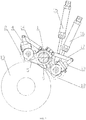
- the inking mechanism of the offset printing apparatus in the present embodiment includes the ink vibrator 1.
- the front side of the ink vibrator 1 is connected to the first shaft 21 through the first swinging arm 5.
- the first shaft 21 is provided with the first inking roller 2.
- the back side of the ink vibrator 1 is connected to the second shaft 22 through the second swinging arm 9.
- the second shaft 22 is provided with the second inking roller 12.
- the swing of the first swinging arm 5 and the second swinging arm 9 can adjust the positions of the first inking roller 2 and second inking roller 12, so that the first inking roller 2 and second inking roller 12 are respectively cooperating with and roll oppositely with the plating rollers 13 of different sizes so as to transfer ink.
- the first inking roller 2 and the second inking roller 12 usually adopt the rubber rollers.
- the fifth bearing is arranged between the first inking roller 2 and the first shaft 21, and the sixth bearing is arranged between the second inking roller 12 and the second shaft 22.
- the seventh bearing is arranged between the first shaft 21 and the first swinging arm 5
- the eighth bearing is arranged between the second shaft 22 and the second swinging arm 9, so that the first inking roller 2 and the second inking roller 12 oppositely roll with and cooperate with the plating roller 13.
- the printing press includes an offset printing unit, and the offset printing unit includes the inking mechanism of the offset printing apparatus.
- the left side and the right side of the first inking roller 2 are respectively provided with the first holder 4.
- the first holder 4 is connected to the first shaft 21.
- the first holder 4 is rotatably arranged relative to the first shaft 21.
- the first holder 4 can rotate relative to the first shaft 21 by connecting and setting a corresponding rotating inner sleeve or a bearing.
- the first holder 4 is provided with the first roller bearer 3.
- the first roller bearer 3 is cooperating with and rolls oppositely with the roller bearer on the plating roller 13 to make the pressure more stable.
- the left side and the right side of the second inking roller 12 are respectively connected to the second holder 10.
- the second holder 10 is connected to the second shaft 22.
- the second holder 10 is rotatably arranged relative to the second shaft 22.
- the second holder 10 can rotate relative to the second shaft 22 by connecting and setting a corresponding rotating inner sleeve or a bearing.
- the second holder 10 is provided with the second roller bearer 11.
- the second roller bearer 11 rolls oppositely with and is cooperating with the roller bearer on the plating roller 13 to make the pressure more stable.
- the first roller bearers 3 on both sides of the first inking roller 2 can roll oppositely with the roller bearers on both sides of the plating roller 13.
- the second roller bearers 11 on both sides of the second inking roller 12 can also roll oppositely with the roller bearers on both sides of the plating roller 13, so as to achieve a stable rolling pressure between the first inking roller 2 and the plating roller 13, and a stable rolling pressure between the second inking roller 12 and the plating roller 13.
- the first pull arm 14 is connected between the first holder 4 and the second swinging arm 9.
- the first holder 4 and the second swinging arm 9 are respectively hinged to the first pull arm 14.
- the second pull arm 17 is connected between the second holder 10 and the first swinging arm 5.
- the second holder 10 and the first swinging arm 5 are respectively hinged to the second pull arm 17.
- the first inking roller 2 and the second inking roller 12 are cooperating with the plating roller 13 to transfer ink by the movement of the first swinging arm 5 and the second swinging arm 9.
- the first pull arm 14, the second pull arm 17, the first swinging arm 5 and the second swinging arm 9 are cooperating with one another, so that the position of the mating point where the first roller bearer 3 and the second roller bearer 11 roll oppositely with the roller bearers on both sides of the plating roller 13 is changed less.
- the pressure of the first inking roller 2 and the second inking roller 12 which are matched with the plating roller 13 is changed less and relatively stable, without affecting the printing quality and effect. According to FIGS.
- the second swinging arm 9 swings clockwise, the second swinging arm 17 pulls the second holder 10 and the first swinging arm 5, the second holder 10 rotates counterclockwise when the second swinging arm 9 swings clockwise, so that the second roller bearer 11 on the second holder 10 rotates counterclockwise synchronously, and the position of the matching point of the second roller bearer 11 and the roller bearers on the plating roller 13 is less changed compared with the position of the matching point of the second roller bearer 11 and the roller bearers on the plating roller 13 with a larger outer dimension.
- an opposite matching action is performed.
- the first swinging arm 5 is connected to the first transmission device 15, and the first swinging arm 5 is driven to swing around the center of the ink vibrator 1 by the first transmission device.
- the second swinging arm 9 is connected to the second transmission device 16, and the second swinging arm 9 is driven to swing around the center of the ink vibrator 1 by the second transmission device.
- An air cylinder, or a motor, can be used as a power source to drive the first transmission device and the second transmission device, and the embodiments all adopt the air cylinder.
- the first swinging arm 5 and the second swinging arm 9 are hinged to the roll shaft 8 of the ink vibrator 1.
- the first swinging arm 5 and the second swinging arm 9 can be hinged to the roll sleeve 7 of the roll shaft 8 to swing.
- the roll shaft 8 of the ink vibrator 1 is connected in the roll sleeve 7, and the roll shaft 8 is supported by the roll sleeve 7 to rotate and axially move.
- the roll sleeve 7 is connected to the frame 6.
- the first swinging arm 5 and the second swinging arm 9 are respectively hinged to the roll sleeve 7.
- the first swinging arm 5 and the second swinging arm 9 swing around the roll sleeve 7.
- the ink vibrator 1 is matched with and oppositely rolls with the first inking roller 2.
- the ink vibrator 1 is matched with and oppositely rolls with the second inking roller 12.
- the first eccentric sleeve 23 is additionally arranged between the roll sleeve 7 and the first swinging arm 5.
- the first eccentric sleeve 23 can be rotatably adjusted to adjust the fitting pressure between the first inking roller 2 and the ink vibrator 1.
- the second eccentric sleeve 24 is arranged between the roll sleeve 7 and the second swinging arm 9.
- the second eccentric sleeve 24 can be rotatably adjusted to adjust the fitting pressure between the second inking roller 12 and the ink vibrator 1. Further, the pressure between the ink vibrator 1 and the first inking roller 2, and the pressure between the ink vibrator 1 and the second inking roller 12 can be adjusted.
- the first roller bearer 3 is arranged on the first holder 4 to rotate around its center of the first holder 4.
- the first bearing 27 is arranged to allow the first roller bearer 3 to rotate.
- the first roller bearer 3 is arranged on the first holder 4 through the first radial adjustment device. The relative radial position of the first roller bearer 3 and the first shaft 21 is adjusted by the radial adjustment device.
- the axial center of the first roller bearer 3 is adjusted by the radial adjustment device, so as to change the distance of the axial center between the first roller bearer 3 on the first shaft 21 and the roller bearer (i.e., the plating roller bearer) on the plating roller which are press-fitted with one another, thereby realizing an adjustment of the fitting pressure between the first inking roll 2 on the first shaft 21, and the plating roller which are matched with one another.
- the first radial adjustment device includes the third eccentric sleeve 25.
- the third eccentric sleeve 25 is sleeved on the first shaft 21.
- the third eccentric sleeve 25 is arranged relative to the first shaft 21 and capable of being adjusted by rotation.
- the first roller bearer 3 is sleeved outside the third eccentric sleeve 25.
- the first roller bearer 3 is rotatably arranged relative to the third eccentric sleeve 25.
- the axial center of the first roller bearer 3 can be adjusted by rotatably adjusting the position of the third eccentric sleeve 25 and adjusting the relative radial position of the first roller bearer 3 and the first shaft 21, so as to change the distance of the axial center between the first roller bearer 3 on the first shaft 21 and the roller bearer on the plating roller 13 which are press-fitted with one another, thereby achieving an adjustment of the fitting pressure.
- the first worm gear 26 is sleeved on the first shaft 21, and the first worm gear 26 is rotatably arranged relative to the first shaft 21.
- the first rotating inner sleeve 28 or the second bearing (not shown) is arranged to allow the first worm gear 26 to rotate on the first shaft 21.
- the first worm gear 26 is connected to the third eccentric sleeve 25.
- the first worm gear 26 and the third eccentric sleeve 25 rotate synchronously.
- the first worm gear 26 is connected to the drive of the first worm (not shown).
- the first worm is arranged on the first holder 4 and capable of being adjusted by rotation, and the first worm is rotated to drive the first worm gear 26 to rotate.
- the first bearing 27 is arranged between the first roller bearer 3 and the third eccentric sleeve 25.
- the first rotating inner sleeve 28 is arranged on the first shaft 21.
- the first holder 4 is connected to the first rotating inner sleeve 28.
- the third eccentric sleeve 25 and the first worm gear 26 are sleeved on the first rotating inner sleeve 28 of the first shaft 21.
- the third eccentric sleeve 25 and the first worm gear 26 are integrally arranged or separately arranged. Namely, the first worm gear 26 and the third eccentric sleeve 25 can be connected to form an integral structure or a separated structure.
- the first roller bearer 3 is arranged on the third eccentric sleeve 25 through the first bearing 27, so that the first roller bearer 3 rotates on the third eccentric sleeve 25.
- the third eccentric sleeve 25 is connected to the first worm gear 26 (the third eccentric sleeve 25 and the first worm gear 26 are integrally arranged or separately arranged).
- the first worm gear 26 and the third eccentric sleeve 25 are arranged on the first shaft 21 through the first rotating inner sleeve 28 or the second bearing (not shown).
- the first worm gear 26 and the third eccentric sleeve 25 will rotate synchronously on the first shaft 21.
- the first worm gear 26 is connected to the drive of the first worm (not shown).
- the first worm is connected to the first holder 4.
- the first worm on the first holder 4 can be adjusted to drive the first worm gear 26 to rotate.
- the first holder 4 is connected to the first worm gear 26 through the first worm, which enables the first holder 4 to be connected to the first rotating inner sleeve 28.
- the distance of the axial center between the first roller bearer 3 on the first shaft 21 and the roller bearer (i.e., the plating roller bearer) on the plating roller 13 which are press-fitted with one another is changed, so as to realize an adjustment of the fitting pressure between the first inking roller 2 on the first shaft 21 and the plating roller 13 which are matched with one another.
- the second roller bearer 11 is rotatably arranged on the second holder 10 to rotate around the center of the second holder 10.
- the third bearing 31 is arranged to allow the second roller bearer 11 to rotate.
- the second roller bearer 11 is arranged on the second holder 10 through the second radial adjustment device. The relative radial position of the second roller bearer 11 and the second shaft 22 is adjusted through the radial adjustment device.
- the position of the axial center of the second roller bearer 11 is adjusted through the radial adjustment device, so as to change the distance of the axial center between the second roller bearer 11 on the second shaft 22 and the roller bearer (i.e., the plating roller bearer) on the plating roller 13 which are press-fitted with one another, thereby achieving an adjustment of the fitting pressure between the second inking roller 12 on the second shaft 22 and the plating roller 13 which are matched with one another.
- the second radial adjustment device includes the fourth eccentric sleeve 29.
- the fourth eccentric sleeve 29 is sleeved on the second shaft 22.
- the fourth eccentric sleeve 29 is arranged relative to the second shaft 22 and capable of being adjusted by rotation.
- the second roller bearer 11 is sleeved outside the fourth eccentric sleeve 29.
- the second roller bearer 11 is rotatably arranged relative to the fourth eccentric sleeve 29.
- the position of the axial center of the second roller bearer 11 can be adjusted by rotatably adjusting the position of the fourth eccentric sleeve 29 and adjusting the relative radial position of the second roller bearer 11 and the second shaft 22, so as to change the distance of the axial center between the second roller bearer 11 on the second shaft 22 and the roller bearer on the plating roller 13 which are press-fitted with one another, thereby realizing an adjustment of the fitting pressure.
- the second worm gear 30 is sleeved on the second shaft 22.
- the second worm gear 30 is rotatably arranged relative to the second shaft 22.
- the second rotating inner sleeve 32 or the fourth bearing is arranged to allow the second worm gear 30 to rotate on the second shaft 22.
- the second worm gear 30 is connected to the fourth eccentric sleeve 29.
- the second worm gear 30 and the fourth eccentric sleeve 29 will rotate synchronously.
- the second worm gear 30 is connected to the drive of the second worm.
- the second worm is arranged on the second holder 10 and capable of being adjusted by rotation.
- the second worm is rotated to drive the second worm gear 30 to rotate.
- the third bearing 31 is arranged between the second roller bearer 11 and the fourth eccentric sleeve 29.
- the second rotating inner sleeve 32 is arranged on the second shaft 22.
- the second holder 10 is connected to the second rotating inner sleeve 32.
- the fourth eccentric sleeve 29 and the second worm gear 30 are sleeved on the second rotating inner sleeve 32 of the second shaft 22.
- the fourth eccentric sleeve 29 and the second worm gear 30 are integrally arranged or separately arranged. Namely, the second worm gear 30 and the fourth eccentric sleeve 29 can be connected to form an integral structure or a separated structure.
- the second roller bearer 11 is arranged on the fourth eccentric sleeve 29 through the third bearing 31 so that the second roller bearer 11 rotates on the fourth eccentric sleeve 29.
- the fourth eccentric sleeve 29 is connected to the second worm gear 30 (the fourth eccentric sleeve 29 and the second worm gear 30 are integrally arranged or separately arranged).
- the second worm gear 30 and the fourth eccentric sleeve 29 are arranged on the second shaft 22 through the second rotating inner sleeve 32 or the fourth bearing.
- the second worm gear 30 and the fourth eccentric sleeve 29 will rotate on the second shaft 22 synchronously.
- the second worm gear 30 is connected to the drive of the second worm.
- the second worm is connected and arranged on the second holder 10.
- the second worm on the second holder 10 can be adjusted to drive the second worm gear 30 to rotate.
- the second holder 10 is connected to the second worm gear 30 through the second worm, which enables the second holder 10 to be connected to the second rotating inner sleeve 32.
- the distance of the axial center between the second roller bearer 11 on the second shaft 22 and the roller bearer (i.e., the plating roller bearer) on the plating roller 13 which are press-fitted with one another is adjusted to realize an adjustment of the fitting pressure between the second inking roller 12 on the second shaft 22 and the plating roller 13 which are matched with one another.
Landscapes
- Engineering & Computer Science (AREA)
- Mechanical Engineering (AREA)
- Inking, Control Or Cleaning Of Printing Machines (AREA)
Applications Claiming Priority (2)
| Application Number | Priority Date | Filing Date | Title |
|---|---|---|---|
| CN201910339248.3A CN110001187B (zh) | 2019-04-25 | 2019-04-25 | 胶印设备的着墨机构和印刷机 |
| PCT/CN2019/117374 WO2020215674A1 (fr) | 2019-04-25 | 2019-11-12 | Mécanisme d'encrage pour dispositif d'impression offset et machine d'impression |
Publications (3)
| Publication Number | Publication Date |
|---|---|
| EP3750711A4 EP3750711A4 (fr) | 2020-12-16 |
| EP3750711A1 true EP3750711A1 (fr) | 2020-12-16 |
| EP3750711B1 EP3750711B1 (fr) | 2021-12-22 |
Family
ID=67174222
Family Applications (1)
| Application Number | Title | Priority Date | Filing Date |
|---|---|---|---|
| EP19850784.0A Active EP3750711B1 (fr) | 2019-04-25 | 2019-11-12 | Mécanisme d'encrage pour dispositif d'impression offset et machine d'impression |
Country Status (5)
| Country | Link |
|---|---|
| EP (1) | EP3750711B1 (fr) |
| CN (1) | CN110001187B (fr) |
| DK (1) | DK3750711T3 (fr) |
| ES (1) | ES2908036T3 (fr) |
| WO (1) | WO2020215674A1 (fr) |
Families Citing this family (2)
| Publication number | Priority date | Publication date | Assignee | Title |
|---|---|---|---|---|
| CN110001187B (zh) * | 2019-04-25 | 2023-08-29 | 浙江炜冈科技股份有限公司 | 胶印设备的着墨机构和印刷机 |
| CN118596689B (zh) * | 2024-06-11 | 2025-07-25 | 浙江炜冈科技股份有限公司 | 印版滚筒的着墨机构和印刷机 |
Family Cites Families (19)
| Publication number | Priority date | Publication date | Assignee | Title |
|---|---|---|---|---|
| JPS63251237A (ja) * | 1987-04-08 | 1988-10-18 | Komori Printing Mach Co Ltd | 輪転印刷機のインキ装置 |
| CN2073814U (zh) * | 1990-08-16 | 1991-03-27 | 中国人民银行印制总公司 | 对开单色印码机 |
| DE4140219C2 (de) * | 1991-12-06 | 1993-11-04 | Koenig & Bauer Ag | Lageranordnung fuer eine auftragswalze einer druckmaschine |
| DE19541418A1 (de) * | 1995-11-07 | 1997-05-15 | Heidelberger Druckmasch Ag | Offsetdruckmaschine |
| US6058837A (en) * | 1997-08-08 | 2000-05-09 | Komori Corporation | Inking device for printing machine |
| US6082257A (en) * | 1998-08-19 | 2000-07-04 | Howard W. DeMoore | Printing unit with anilox roller bearer positioning |
| DE10023605A1 (de) * | 2000-05-15 | 2002-06-27 | Roland Man Druckmasch | Vorrichtung zum Einstellen einer Auftragwalze am Plattenzylinder einer Druckmaschine |
| JP2007007874A (ja) * | 2005-06-28 | 2007-01-18 | Mitsubishi Heavy Ind Ltd | 着けローラ支持装置およびこれを用いた印刷ユニット |
| DE102007052761B4 (de) * | 2006-11-20 | 2018-02-22 | Heidelberger Druckmaschinen Ag | Anilox-Druckwerk |
| CN101264685A (zh) * | 2008-04-23 | 2008-09-17 | 潍坊华光精工设备有限公司 | 印刷机酒精润版机构 |
| CN201721111U (zh) * | 2010-05-20 | 2011-01-26 | 江苏昌昇集团股份有限公司 | 一种大幅面全张机酒精润版装置 |
| CN208118649U (zh) * | 2018-04-16 | 2018-11-20 | 浙江中特机械科技有限公司 | 印刷机可变径滚筒靠版辊调节机构 |
| CN208290733U (zh) * | 2018-05-31 | 2018-12-28 | 浙江炜冈机械有限公司 | 一种胶印印刷机构 |
| CN108528041B (zh) * | 2018-05-31 | 2023-10-10 | 浙江炜冈科技股份有限公司 | 一种胶印印刷机构 |
| CN108544834B (zh) * | 2018-06-12 | 2024-01-23 | 浙江炜冈科技股份有限公司 | 新型胶印印刷机构 |
| CN208714649U (zh) * | 2018-08-02 | 2019-04-09 | 浙江通得数字印刷设备制造有限公司 | 一种靠版辊和版滚筒间压力调节装置及胶印机 |
| CN109514992B (zh) * | 2018-12-20 | 2024-04-02 | 浙江炜冈科技股份有限公司 | 着墨辊机构和印刷机 |
| CN210026610U (zh) * | 2019-04-25 | 2020-02-07 | 浙江炜冈机械股份有限公司 | 胶印设备的着墨机构和印刷机 |
| CN110001187B (zh) * | 2019-04-25 | 2023-08-29 | 浙江炜冈科技股份有限公司 | 胶印设备的着墨机构和印刷机 |
-
2019
- 2019-04-25 CN CN201910339248.3A patent/CN110001187B/zh active Active
- 2019-11-12 ES ES19850784T patent/ES2908036T3/es active Active
- 2019-11-12 EP EP19850784.0A patent/EP3750711B1/fr active Active
- 2019-11-12 DK DK19850784.0T patent/DK3750711T3/da active
- 2019-11-12 WO PCT/CN2019/117374 patent/WO2020215674A1/fr not_active Ceased
Also Published As
| Publication number | Publication date |
|---|---|
| EP3750711A4 (fr) | 2020-12-16 |
| WO2020215674A1 (fr) | 2020-10-29 |
| DK3750711T3 (da) | 2022-03-07 |
| CN110001187A (zh) | 2019-07-12 |
| EP3750711B1 (fr) | 2021-12-22 |
| ES2908036T3 (es) | 2022-04-27 |
| CN110001187B (zh) | 2023-08-29 |
Similar Documents
| Publication | Publication Date | Title |
|---|---|---|
| JP2585995Y2 (ja) | 胴着脱装置 | |
| EP2409837B1 (fr) | Dispositif de réglage automatique de registre pour machine d'impression de tasse | |
| CN106739482B (zh) | 一种可变规格印刷机的水墨辊离合机构 | |
| EP3750711A1 (fr) | Mécanisme d'encrage pour dispositif d'impression offset et machine d'impression | |
| CN208148747U (zh) | 靠版辊机构、着水着墨装置、供水供墨系统、胶印机及胶印线 | |
| CN104245314B (zh) | 凹版印刷机 | |
| EP3632684B1 (fr) | Mécanisme d'impression d'une machine d'impression offset | |
| GB923933A (en) | Improvements in printing press | |
| CN211416590U (zh) | 一种纸板印刷辊的压力调节装置 | |
| CN210026609U (zh) | 胶印设备的匀水机构和印刷机 | |
| CN109514992B (zh) | 着墨辊机构和印刷机 | |
| CN210026610U (zh) | 胶印设备的着墨机构和印刷机 | |
| CN2614899Y (zh) | 轮转式印刷机胶印机组的柔印插件 | |
| JP4505200B2 (ja) | 印刷機で押し当てと押し離しをする装置 | |
| CN217705164U (zh) | 用于轮转胶印机的着墨调节装置 | |
| CN209666585U (zh) | 着墨辊机构和印刷机 | |
| JP2019064202A5 (fr) | ||
| CN218664433U (zh) | 一种胶印印刷机的纸张定位机构 | |
| CN107584861B (zh) | 含胶印单元和柔印单元的印刷机组 | |
| CN209666533U (zh) | 胶印机构和印刷机 | |
| CN211542799U (zh) | 转印摆臂装置和印刷机 | |
| CN107297947B (zh) | 新型间歇式胶印机 | |
| CN101641215B (zh) | 齿轮传动的可变裁切印刷机 | |
| CN207190486U (zh) | 胶印机的印刷机构 | |
| CN213108678U (zh) | 一种微型的印刷窜墨机构 |
Legal Events
| Date | Code | Title | Description |
|---|---|---|---|
| STAA | Information on the status of an ep patent application or granted ep patent |
Free format text: STATUS: UNKNOWN |
|
| STAA | Information on the status of an ep patent application or granted ep patent |
Free format text: STATUS: THE INTERNATIONAL PUBLICATION HAS BEEN MADE |
|
| PUAI | Public reference made under article 153(3) epc to a published international application that has entered the european phase |
Free format text: ORIGINAL CODE: 0009012 |
|
| STAA | Information on the status of an ep patent application or granted ep patent |
Free format text: STATUS: REQUEST FOR EXAMINATION WAS MADE |
|
| 17P | Request for examination filed |
Effective date: 20200226 |
|
| A4 | Supplementary search report drawn up and despatched |
Effective date: 20201007 |
|
| AK | Designated contracting states |
Kind code of ref document: A1 Designated state(s): AL AT BE BG CH CY CZ DE DK EE ES FI FR GB GR HR HU IE IS IT LI LT LU LV MC MK MT NL NO PL PT RO RS SE SI SK SM TR |
|
| AX | Request for extension of the european patent |
Extension state: BA ME |
|
| R17P | Request for examination filed (corrected) |
Effective date: 20200226 |
|
| STAA | Information on the status of an ep patent application or granted ep patent |
Free format text: STATUS: EXAMINATION IS IN PROGRESS |
|
| 17Q | First examination report despatched |
Effective date: 20210630 |
|
| GRAP | Despatch of communication of intention to grant a patent |
Free format text: ORIGINAL CODE: EPIDOSNIGR1 |
|
| STAA | Information on the status of an ep patent application or granted ep patent |
Free format text: STATUS: GRANT OF PATENT IS INTENDED |
|
| DAV | Request for validation of the european patent (deleted) | ||
| DAX | Request for extension of the european patent (deleted) | ||
| INTG | Intention to grant announced |
Effective date: 20210930 |
|
| GRAS | Grant fee paid |
Free format text: ORIGINAL CODE: EPIDOSNIGR3 |
|
| GRAA | (expected) grant |
Free format text: ORIGINAL CODE: 0009210 |
|
| STAA | Information on the status of an ep patent application or granted ep patent |
Free format text: STATUS: THE PATENT HAS BEEN GRANTED |
|
| RAP3 | Party data changed (applicant data changed or rights of an application transferred) |
Owner name: ZHEJIANG WEIGANG TECHNOLOGY CO., LTD. |
|
| AK | Designated contracting states |
Kind code of ref document: B1 Designated state(s): AL AT BE BG CH CY CZ DE DK EE ES FI FR GB GR HR HU IE IS IT LI LT LU LV MC MK MT NL NO PL PT RO RS SE SI SK SM TR |
|
| REG | Reference to a national code |
Ref country code: GB Ref legal event code: FG4D |
|
| REG | Reference to a national code |
Ref country code: CH Ref legal event code: EP |
|
| REG | Reference to a national code |
Ref country code: DE Ref legal event code: R096 Ref document number: 602019010330 Country of ref document: DE |
|
| REG | Reference to a national code |
Ref country code: AT Ref legal event code: REF Ref document number: 1456832 Country of ref document: AT Kind code of ref document: T Effective date: 20220115 |
|
| REG | Reference to a national code |
Ref country code: IE Ref legal event code: FG4D |
|
| REG | Reference to a national code |
Ref country code: DK Ref legal event code: T3 Effective date: 20220303 |
|
| REG | Reference to a national code |
Ref country code: NL Ref legal event code: FP |
|
| REG | Reference to a national code |
Ref country code: LT Ref legal event code: MG9D |
|
| REG | Reference to a national code |
Ref country code: ES Ref legal event code: FG2A Ref document number: 2908036 Country of ref document: ES Kind code of ref document: T3 Effective date: 20220427 |
|
| PG25 | Lapsed in a contracting state [announced via postgrant information from national office to epo] |
Ref country code: RS Free format text: LAPSE BECAUSE OF FAILURE TO SUBMIT A TRANSLATION OF THE DESCRIPTION OR TO PAY THE FEE WITHIN THE PRESCRIBED TIME-LIMIT Effective date: 20211222 Ref country code: LT Free format text: LAPSE BECAUSE OF FAILURE TO SUBMIT A TRANSLATION OF THE DESCRIPTION OR TO PAY THE FEE WITHIN THE PRESCRIBED TIME-LIMIT Effective date: 20211222 Ref country code: FI Free format text: LAPSE BECAUSE OF FAILURE TO SUBMIT A TRANSLATION OF THE DESCRIPTION OR TO PAY THE FEE WITHIN THE PRESCRIBED TIME-LIMIT Effective date: 20211222 Ref country code: BG Free format text: LAPSE BECAUSE OF FAILURE TO SUBMIT A TRANSLATION OF THE DESCRIPTION OR TO PAY THE FEE WITHIN THE PRESCRIBED TIME-LIMIT Effective date: 20220322 |
|
| REG | Reference to a national code |
Ref country code: AT Ref legal event code: MK05 Ref document number: 1456832 Country of ref document: AT Kind code of ref document: T Effective date: 20211222 |
|
| PG25 | Lapsed in a contracting state [announced via postgrant information from national office to epo] |
Ref country code: SE Free format text: LAPSE BECAUSE OF FAILURE TO SUBMIT A TRANSLATION OF THE DESCRIPTION OR TO PAY THE FEE WITHIN THE PRESCRIBED TIME-LIMIT Effective date: 20211222 Ref country code: NO Free format text: LAPSE BECAUSE OF FAILURE TO SUBMIT A TRANSLATION OF THE DESCRIPTION OR TO PAY THE FEE WITHIN THE PRESCRIBED TIME-LIMIT Effective date: 20220322 Ref country code: LV Free format text: LAPSE BECAUSE OF FAILURE TO SUBMIT A TRANSLATION OF THE DESCRIPTION OR TO PAY THE FEE WITHIN THE PRESCRIBED TIME-LIMIT Effective date: 20211222 Ref country code: HR Free format text: LAPSE BECAUSE OF FAILURE TO SUBMIT A TRANSLATION OF THE DESCRIPTION OR TO PAY THE FEE WITHIN THE PRESCRIBED TIME-LIMIT Effective date: 20211222 Ref country code: GR Free format text: LAPSE BECAUSE OF FAILURE TO SUBMIT A TRANSLATION OF THE DESCRIPTION OR TO PAY THE FEE WITHIN THE PRESCRIBED TIME-LIMIT Effective date: 20220323 |
|
| PG25 | Lapsed in a contracting state [announced via postgrant information from national office to epo] |
Ref country code: SM Free format text: LAPSE BECAUSE OF FAILURE TO SUBMIT A TRANSLATION OF THE DESCRIPTION OR TO PAY THE FEE WITHIN THE PRESCRIBED TIME-LIMIT Effective date: 20211222 Ref country code: SK Free format text: LAPSE BECAUSE OF FAILURE TO SUBMIT A TRANSLATION OF THE DESCRIPTION OR TO PAY THE FEE WITHIN THE PRESCRIBED TIME-LIMIT Effective date: 20211222 Ref country code: RO Free format text: LAPSE BECAUSE OF FAILURE TO SUBMIT A TRANSLATION OF THE DESCRIPTION OR TO PAY THE FEE WITHIN THE PRESCRIBED TIME-LIMIT Effective date: 20211222 Ref country code: PT Free format text: LAPSE BECAUSE OF FAILURE TO SUBMIT A TRANSLATION OF THE DESCRIPTION OR TO PAY THE FEE WITHIN THE PRESCRIBED TIME-LIMIT Effective date: 20220422 Ref country code: EE Free format text: LAPSE BECAUSE OF FAILURE TO SUBMIT A TRANSLATION OF THE DESCRIPTION OR TO PAY THE FEE WITHIN THE PRESCRIBED TIME-LIMIT Effective date: 20211222 Ref country code: CZ Free format text: LAPSE BECAUSE OF FAILURE TO SUBMIT A TRANSLATION OF THE DESCRIPTION OR TO PAY THE FEE WITHIN THE PRESCRIBED TIME-LIMIT Effective date: 20211222 |
|
| PG25 | Lapsed in a contracting state [announced via postgrant information from national office to epo] |
Ref country code: PL Free format text: LAPSE BECAUSE OF FAILURE TO SUBMIT A TRANSLATION OF THE DESCRIPTION OR TO PAY THE FEE WITHIN THE PRESCRIBED TIME-LIMIT Effective date: 20211222 Ref country code: AT Free format text: LAPSE BECAUSE OF FAILURE TO SUBMIT A TRANSLATION OF THE DESCRIPTION OR TO PAY THE FEE WITHIN THE PRESCRIBED TIME-LIMIT Effective date: 20211222 |
|
| REG | Reference to a national code |
Ref country code: DE Ref legal event code: R097 Ref document number: 602019010330 Country of ref document: DE |
|
| PG25 | Lapsed in a contracting state [announced via postgrant information from national office to epo] |
Ref country code: IS Free format text: LAPSE BECAUSE OF FAILURE TO SUBMIT A TRANSLATION OF THE DESCRIPTION OR TO PAY THE FEE WITHIN THE PRESCRIBED TIME-LIMIT Effective date: 20220422 |
|
| PLBE | No opposition filed within time limit |
Free format text: ORIGINAL CODE: 0009261 |
|
| STAA | Information on the status of an ep patent application or granted ep patent |
Free format text: STATUS: NO OPPOSITION FILED WITHIN TIME LIMIT |
|
| PG25 | Lapsed in a contracting state [announced via postgrant information from national office to epo] |
Ref country code: AL Free format text: LAPSE BECAUSE OF FAILURE TO SUBMIT A TRANSLATION OF THE DESCRIPTION OR TO PAY THE FEE WITHIN THE PRESCRIBED TIME-LIMIT Effective date: 20211222 |
|
| 26N | No opposition filed |
Effective date: 20220923 |
|
| PG25 | Lapsed in a contracting state [announced via postgrant information from national office to epo] |
Ref country code: SI Free format text: LAPSE BECAUSE OF FAILURE TO SUBMIT A TRANSLATION OF THE DESCRIPTION OR TO PAY THE FEE WITHIN THE PRESCRIBED TIME-LIMIT Effective date: 20211222 |
|
| PG25 | Lapsed in a contracting state [announced via postgrant information from national office to epo] |
Ref country code: MC Free format text: LAPSE BECAUSE OF FAILURE TO SUBMIT A TRANSLATION OF THE DESCRIPTION OR TO PAY THE FEE WITHIN THE PRESCRIBED TIME-LIMIT Effective date: 20211222 |
|
| PG25 | Lapsed in a contracting state [announced via postgrant information from national office to epo] |
Ref country code: LU Free format text: LAPSE BECAUSE OF NON-PAYMENT OF DUE FEES Effective date: 20221112 |
|
| PG25 | Lapsed in a contracting state [announced via postgrant information from national office to epo] |
Ref country code: IE Free format text: LAPSE BECAUSE OF NON-PAYMENT OF DUE FEES Effective date: 20221112 |
|
| PG25 | Lapsed in a contracting state [announced via postgrant information from national office to epo] |
Ref country code: CY Free format text: LAPSE BECAUSE OF FAILURE TO SUBMIT A TRANSLATION OF THE DESCRIPTION OR TO PAY THE FEE WITHIN THE PRESCRIBED TIME-LIMIT Effective date: 20211222 |
|
| PG25 | Lapsed in a contracting state [announced via postgrant information from national office to epo] |
Ref country code: MK Free format text: LAPSE BECAUSE OF FAILURE TO SUBMIT A TRANSLATION OF THE DESCRIPTION OR TO PAY THE FEE WITHIN THE PRESCRIBED TIME-LIMIT Effective date: 20211222 Ref country code: HU Free format text: LAPSE BECAUSE OF FAILURE TO SUBMIT A TRANSLATION OF THE DESCRIPTION OR TO PAY THE FEE WITHIN THE PRESCRIBED TIME-LIMIT; INVALID AB INITIO Effective date: 20191112 |
|
| GBPC | Gb: european patent ceased through non-payment of renewal fee |
Effective date: 20231112 |
|
| PG25 | Lapsed in a contracting state [announced via postgrant information from national office to epo] |
Ref country code: MT Free format text: LAPSE BECAUSE OF FAILURE TO SUBMIT A TRANSLATION OF THE DESCRIPTION OR TO PAY THE FEE WITHIN THE PRESCRIBED TIME-LIMIT Effective date: 20211222 |
|
| PG25 | Lapsed in a contracting state [announced via postgrant information from national office to epo] |
Ref country code: GB Free format text: LAPSE BECAUSE OF NON-PAYMENT OF DUE FEES Effective date: 20231112 |
|
| PG25 | Lapsed in a contracting state [announced via postgrant information from national office to epo] |
Ref country code: GB Free format text: LAPSE BECAUSE OF NON-PAYMENT OF DUE FEES Effective date: 20231112 |
|
| PGFP | Annual fee paid to national office [announced via postgrant information from national office to epo] |
Ref country code: DK Payment date: 20250904 Year of fee payment: 7 |
|
| PGFP | Annual fee paid to national office [announced via postgrant information from national office to epo] |
Ref country code: NL Payment date: 20250918 Year of fee payment: 7 |
|
| PGFP | Annual fee paid to national office [announced via postgrant information from national office to epo] |
Ref country code: BE Payment date: 20250918 Year of fee payment: 7 |
|
| PGFP | Annual fee paid to national office [announced via postgrant information from national office to epo] |
Ref country code: FR Payment date: 20250904 Year of fee payment: 7 |
|
| REG | Reference to a national code |
Ref country code: CH Ref legal event code: U11 Free format text: ST27 STATUS EVENT CODE: U-0-0-U10-U11 (AS PROVIDED BY THE NATIONAL OFFICE) Effective date: 20251201 |
|
| PG25 | Lapsed in a contracting state [announced via postgrant information from national office to epo] |
Ref country code: TR Free format text: LAPSE BECAUSE OF FAILURE TO SUBMIT A TRANSLATION OF THE DESCRIPTION OR TO PAY THE FEE WITHIN THE PRESCRIBED TIME-LIMIT Effective date: 20211222 |
|
| PGFP | Annual fee paid to national office [announced via postgrant information from national office to epo] |
Ref country code: DE Payment date: 20250919 Year of fee payment: 7 |
|
| PGFP | Annual fee paid to national office [announced via postgrant information from national office to epo] |
Ref country code: IT Payment date: 20250919 Year of fee payment: 7 |
|
| PGFP | Annual fee paid to national office [announced via postgrant information from national office to epo] |
Ref country code: CH Payment date: 20251201 Year of fee payment: 7 |
|
| PGFP | Annual fee paid to national office [announced via postgrant information from national office to epo] |
Ref country code: ES Payment date: 20251218 Year of fee payment: 7 |