EP3750731A1 - Ladebuchse - Google Patents
Ladebuchse Download PDFInfo
- Publication number
- EP3750731A1 EP3750731A1 EP20172925.8A EP20172925A EP3750731A1 EP 3750731 A1 EP3750731 A1 EP 3750731A1 EP 20172925 A EP20172925 A EP 20172925A EP 3750731 A1 EP3750731 A1 EP 3750731A1
- Authority
- EP
- European Patent Office
- Prior art keywords
- charging socket
- flaps
- rear wall
- frame
- opening
- Prior art date
- Legal status (The legal status is an assumption and is not a legal conclusion. Google has not performed a legal analysis and makes no representation as to the accuracy of the status listed.)
- Granted
Links
Images


Classifications
-
- B—PERFORMING OPERATIONS; TRANSPORTING
- B60—VEHICLES IN GENERAL
- B60K—ARRANGEMENT OR MOUNTING OF PROPULSION UNITS OR OF TRANSMISSIONS IN VEHICLES; ARRANGEMENT OR MOUNTING OF PLURAL DIVERSE PRIME-MOVERS IN VEHICLES; AUXILIARY DRIVES FOR VEHICLES; INSTRUMENTATION OR DASHBOARDS FOR VEHICLES; ARRANGEMENTS IN CONNECTION WITH COOLING, AIR INTAKE, GAS EXHAUST OR FUEL SUPPLY OF PROPULSION UNITS IN VEHICLES
- B60K1/00—Arrangement or mounting of electrical propulsion units
-
- B—PERFORMING OPERATIONS; TRANSPORTING
- B60—VEHICLES IN GENERAL
- B60K—ARRANGEMENT OR MOUNTING OF PROPULSION UNITS OR OF TRANSMISSIONS IN VEHICLES; ARRANGEMENT OR MOUNTING OF PLURAL DIVERSE PRIME-MOVERS IN VEHICLES; AUXILIARY DRIVES FOR VEHICLES; INSTRUMENTATION OR DASHBOARDS FOR VEHICLES; ARRANGEMENTS IN CONNECTION WITH COOLING, AIR INTAKE, GAS EXHAUST OR FUEL SUPPLY OF PROPULSION UNITS IN VEHICLES
- B60K15/00—Arrangement in connection with fuel supply of combustion engines or other fuel consuming energy converters, e.g. fuel cells; Mounting or construction of fuel tanks
- B60K15/03—Fuel tanks
- B60K15/04—Tank inlets
- B60K15/05—Inlet covers
-
- H—ELECTRICITY
- H01—ELECTRIC ELEMENTS
- H01R—ELECTRICALLY-CONDUCTIVE CONNECTIONS; STRUCTURAL ASSOCIATIONS OF A PLURALITY OF MUTUALLY-INSULATED ELECTRICAL CONNECTING ELEMENTS; COUPLING DEVICES; CURRENT COLLECTORS
- H01R13/00—Details of coupling devices of the kinds covered by groups H01R12/70 or H01R24/00 - H01R33/00
- H01R13/44—Means for preventing access to live contacts
- H01R13/447—Shutter or cover plate
- H01R13/453—Shutter or cover plate opened by engagement of counterpart
- H01R13/4536—Inwardly pivoting shutter
-
- B—PERFORMING OPERATIONS; TRANSPORTING
- B60—VEHICLES IN GENERAL
- B60K—ARRANGEMENT OR MOUNTING OF PROPULSION UNITS OR OF TRANSMISSIONS IN VEHICLES; ARRANGEMENT OR MOUNTING OF PLURAL DIVERSE PRIME-MOVERS IN VEHICLES; AUXILIARY DRIVES FOR VEHICLES; INSTRUMENTATION OR DASHBOARDS FOR VEHICLES; ARRANGEMENTS IN CONNECTION WITH COOLING, AIR INTAKE, GAS EXHAUST OR FUEL SUPPLY OF PROPULSION UNITS IN VEHICLES
- B60K15/00—Arrangement in connection with fuel supply of combustion engines or other fuel consuming energy converters, e.g. fuel cells; Mounting or construction of fuel tanks
- B60K15/03—Fuel tanks
- B60K15/04—Tank inlets
- B60K2015/0458—Details of the tank inlet
- B60K2015/0461—Details of the tank inlet comprising a filler pipe shutter, e.g. trap, door or flap for fuel inlet
-
- B—PERFORMING OPERATIONS; TRANSPORTING
- B60—VEHICLES IN GENERAL
- B60K—ARRANGEMENT OR MOUNTING OF PROPULSION UNITS OR OF TRANSMISSIONS IN VEHICLES; ARRANGEMENT OR MOUNTING OF PLURAL DIVERSE PRIME-MOVERS IN VEHICLES; AUXILIARY DRIVES FOR VEHICLES; INSTRUMENTATION OR DASHBOARDS FOR VEHICLES; ARRANGEMENTS IN CONNECTION WITH COOLING, AIR INTAKE, GAS EXHAUST OR FUEL SUPPLY OF PROPULSION UNITS IN VEHICLES
- B60K15/00—Arrangement in connection with fuel supply of combustion engines or other fuel consuming energy converters, e.g. fuel cells; Mounting or construction of fuel tanks
- B60K15/03—Fuel tanks
- B60K15/04—Tank inlets
- B60K15/05—Inlet covers
- B60K2015/0515—Arrangements for closing or opening of inlet cover
- B60K2015/053—Arrangements for closing or opening of inlet cover with hinged connection to the vehicle body
-
- B—PERFORMING OPERATIONS; TRANSPORTING
- B60—VEHICLES IN GENERAL
- B60Y—INDEXING SCHEME RELATING TO ASPECTS CROSS-CUTTING VEHICLE TECHNOLOGY
- B60Y2200/00—Type of vehicle
- B60Y2200/60—Industrial applications, e.g. pipe inspection vehicles
- B60Y2200/62—Conveyors, floor conveyors
-
- Y—GENERAL TAGGING OF NEW TECHNOLOGICAL DEVELOPMENTS; GENERAL TAGGING OF CROSS-SECTIONAL TECHNOLOGIES SPANNING OVER SEVERAL SECTIONS OF THE IPC; TECHNICAL SUBJECTS COVERED BY FORMER USPC CROSS-REFERENCE ART COLLECTIONS [XRACs] AND DIGESTS
- Y02—TECHNOLOGIES OR APPLICATIONS FOR MITIGATION OR ADAPTATION AGAINST CLIMATE CHANGE
- Y02T—CLIMATE CHANGE MITIGATION TECHNOLOGIES RELATED TO TRANSPORTATION
- Y02T10/00—Road transport of goods or passengers
- Y02T10/60—Other road transportation technologies with climate change mitigation effect
- Y02T10/70—Energy storage systems for electromobility, e.g. batteries
-
- Y—GENERAL TAGGING OF NEW TECHNOLOGICAL DEVELOPMENTS; GENERAL TAGGING OF CROSS-SECTIONAL TECHNOLOGIES SPANNING OVER SEVERAL SECTIONS OF THE IPC; TECHNICAL SUBJECTS COVERED BY FORMER USPC CROSS-REFERENCE ART COLLECTIONS [XRACs] AND DIGESTS
- Y02—TECHNOLOGIES OR APPLICATIONS FOR MITIGATION OR ADAPTATION AGAINST CLIMATE CHANGE
- Y02T—CLIMATE CHANGE MITIGATION TECHNOLOGIES RELATED TO TRANSPORTATION
- Y02T10/00—Road transport of goods or passengers
- Y02T10/60—Other road transportation technologies with climate change mitigation effect
- Y02T10/7072—Electromobility specific charging systems or methods for batteries, ultracapacitors, supercapacitors or double-layer capacitors
-
- Y—GENERAL TAGGING OF NEW TECHNOLOGICAL DEVELOPMENTS; GENERAL TAGGING OF CROSS-SECTIONAL TECHNOLOGIES SPANNING OVER SEVERAL SECTIONS OF THE IPC; TECHNICAL SUBJECTS COVERED BY FORMER USPC CROSS-REFERENCE ART COLLECTIONS [XRACs] AND DIGESTS
- Y02—TECHNOLOGIES OR APPLICATIONS FOR MITIGATION OR ADAPTATION AGAINST CLIMATE CHANGE
- Y02T—CLIMATE CHANGE MITIGATION TECHNOLOGIES RELATED TO TRANSPORTATION
- Y02T90/00—Enabling technologies or technologies with a potential or indirect contribution to GHG emissions mitigation
- Y02T90/10—Technologies relating to charging of electric vehicles
- Y02T90/14—Plug-in electric vehicles
Definitions
- the present invention relates to a charging socket for an electrical connector on a vehicle, in particular on an industrial truck.
- a charging socket is provided which is mounted on the vehicle and has, for example, an electrical connector carried on the vehicle.
- An electrically conductive connection to the plug connector of the vehicle is established via the charging socket with an external charging plug in order to be able to exchange electrical power and data with it, for example.
- the charging socket can be arranged behind a hinged door which can be opened by actuating an opening mechanism.
- the disadvantage of this solution is that swivel space must be provided for the hinged door.
- charging sockets which have one or more small spring-loaded flaps that open inward.
- the battery connector is pushed through the resulting opening with a little force.
- the disadvantage of this solution is that the spring-loaded flaps may open when cleaning with a compressed air or water jet and the electrical contacts in the charging socket are not adequately protected.
- the disadvantage overcomes a charging socket with a spring-loaded flap that can be opened outwards. However, this makes access to the charging socket and its electrical contacts on the vehicle more difficult.
- the invention is based on the object of providing a charging socket which offers effective protection against unintentional opening of the charging flap with the best possible ease of use.
- the object is achieved by a charging socket with the features of claim 1.
- the subjects of the subclaims form advantageous configurations.
- a charging socket with an electrical connector for a charging plug is provided.
- the charging socket can be designed in one piece with the electrical connector or the electrical connector is mounted on the charging socket.
- a electrical connector referred to as the vehicle-side part of the electrical connector, while external is referred to as a charging plug.
- the socket according to the invention has a frame with an opening to the electrical connector and a pair of flaps pivotably arranged on pivot axes running parallel to one another. At least one spring element biases the flaps into a closed position. In the case of the charging socket according to the invention, the flaps open inwards by inserting the charging plug into the opening in the frame of the charging socket.
- each of the flaps has a base wall and a rear wall.
- the rear walls are offset according to the invention with respect to an imaginary plane of the opening.
- the rear wall is offset in the direction of the electrical connector, that is, in the direction of the vehicle interior with a charging socket installed in a vehicle.
- a compressed air or water jet directed at the charging socket hits, if it is directed at the opening of the charging socket, essentially on the set-back rear walls of the flaps, whereby a moment that opens the flap can be avoided or significantly reduced.
- the offset (V) of the rear wall is 0.5 to 10 cm and particularly preferably 1 to 6 cm.
- V offset
- H opening height
- V 2 H opening height
- V 1 1 H opening height
- the flap according to the invention is constructed with two wall sections, the base wall and the respective rear wall. Attacking forces therefore mainly act on the rear wall and only partially on the base wall. By interposing the base wall, the rear walls are offset and the opening torque from the rear wall to the flap is reduced overall.
- a bend running parallel to the Schenkachs is preferably provided between the two wall sections.
- the orientation of the kink parallel to the pivot axis ensures that the rear wall, which is arranged offset, essentially closes the opening.
- the base wall and its respective rear wall preferably enclose a right or an obtuse angle with one another, thereby avoiding the formation of a "pocket” or a receptacle between the base and rear wall in which water or compressed air could collect.
- the at least one spring element is attached to both flaps and biases them into the closed position. Attaching the spring element to the two flaps saves installation space for the charging socket in the vehicle interior.
- the at least one spring element can be arranged on the two flaps in a space-saving manner and pretension them against one another into the closed position.
- the at least one spring element preferably runs perpendicular to the pivot axis, with the rear wall further preferably running essentially parallel to the at least one spring element. Due to the arrangement of the spring element perpendicular to the pivot axis, a maximum force of the spring element is opposed to the opening of the two flaps.
- At least one of the base walls has one or more openings, so that, for example, water or compressed air that has entered through the opening in the frame into a space of the charging socket formed by the base and rear wall can escape.
- the electrical connector is protected by the rear wall.
- each flap is equipped with at least one web which extends from the pivot axis in the direction of the rear wall, a distance between the opposite webs of both flaps tapering towards the rear wall. Due to the tapering distance, the flaps are opened by an inserted charging plug.
- the webs themselves extend disk-shaped in the direction from the pivot axis to the rear wall, so that an attacking jet of water or compressed air has no contact surface on the web.
- the frame of the charging socket is equipped with a rectangular opening which is closed by the two flaps.
- the rectangular opening is preferably at least twice as long in a first direction as in a second direction.
- the pivot axes each preferably extend in the first direction in the opening, that is to say in the longer direction.
- a locking mechanism is provided for the two flaps.
- the locking mechanism has at least one unlocking lever which is also accessible in a closed position of the two flaps.
- the flaps are locked in the closed position and are unlocked by actuation of an unlocking lever.
- the release lever or levers are preferably operated by inserting the charging plug into the opening in the frame and pressing against the release lever. If the release lever is actuated, it pivots and rotates at least one locking hook from a position that locks the flaps.
- the at least one locking hook swivels open against a spring force and releases the flaps for swiveling open.
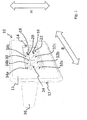
- FIG. 1 shows a charging socket in a perspective view.
- the charging socket 10 has a mounting frame 12 which has a substantially rectangular shape with rounded corners.
- the mounting frame 12 has an essentially flat front panel 13, which is let into the vehicle trim, for example, and ends flush with it or with the formation of a joint.
- the frame has a first dimension H and a second dimension B, which is at least twice as large as the dimension in the direction H.
- an opening 14 Arranged centrally in the frame 12 is an opening 14, which also has a rectangular shape.
- the opening 14 is delimited by edges which run parallel to the outer edges of the frame 12 and its cover plate 13.
- the ratio of the side lengths in the opening 14 to one another corresponds approximately to the ratio of the frame 12 at its outer edges.
- FIG. 1 Clearly recognizable in Figure 1 is the situation that the frame 12 with its opening 14 is not closed flush in the plane of the opening 14 by the two flaps 16, 18.
- the opening 14 is closed by two flaps 16, 18 which are offset inward.
- Each of the flaps 16, 18 has a base wall 20, two side walls 22, 28 along the width B and a rear wall 24, 30 each.
- the rear walls 24 and 30 form a closure of the opening which is offset from the opening 14.
- the walls with the base wall and rear wall meet each other at a bend at an angle of 90 °, so that each flap with its two side walls, the base wall and the rear wall forms four sides of a cuboid.
- a plurality of triangular struts 32a, b, c and 34a, b, c extend between the base wall 20 and the rear wall 24.
- the webs are each arranged parallel to one another and each opposite one another.
- the distance between the (free) legs on the webs 32 and 34 tapers starting with the opening 14 in the frame 12 towards the rear walls 24 and 30 of the flaps.
- FIG. 12 also shows a schematic representation of an electrical connector 36 which, together with the mounting frame 12, forms the charging socket 10.
- Figure 2 shows a perspective view from the perspective of the connector 36, that is, from the inside.
- the frame 12 with the opening 14 can be seen.
- a lower flap 16 and the opposite flap 18 are shown in a partially open position in which the flaps are pivoted.
- the flap 16 is articulated to a lower part of the frame 12 via a pivot axis 38, while the upper flap 18 is articulated to an upper part of the frame 12 via a pivot axis 40.
- Figure 2a also shows the structure of the flaps in connection with the base wall and rear wall.
- the lower flap 16 has a base wall 20 which runs horizontally in the closed state and a rear wall 24 that is perpendicular thereto. Both walls meet at an angle of 90 °.
- the angle in the mathematical sense of rotation
- the angle can also be greater than the 90 ° angle shown. If the angle is greater than 90 °, the rear wall 16 points away from the frame and not towards this or its opening.
- the frame 12 On its side opposite the front plate 13, the frame 12 has a circumferential projection with which the charging socket 10 can be used, for example, in a paneling of the vehicle.
- locking projections 46a, 46b are provided, with which the frame 12 can be clipped into a panel or body component.
- Figure 4 shows the flaps 16 and 18 in the open state. The charging plug 42 has been inserted through the frame 12 into the electrical plug connection 36.
- this Spring element 44 which is attached to the outer wall of the side walls 22 and 28 of flaps 16 and 18, respectively, and biases them into a closed position.
- the charging socket 10 In the event that the charging socket 10 is exposed to a jet of pressurized water, it can be advantageous to provide openings in the base walls through which the liquid can flow off without hitting the electrical connector.
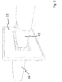
- FIG 2b shows a further possible construction of the charging socket with the flaps 16, 18 closed.
- the frame 12 is shown, which can be mounted via its latching projections 46a, 46b, for example in a recess in the vehicle trim.
- Another frame is provided as a splash guard 17, which is shown in for a better overview Figure 2b is shown in section.
- the frame 12 consists of an L-shaped profile which covers the flaps 16, 18 from the interior.
- the splash guard 17 has two legs standing at right angles to one another, one of which is arranged parallel to the base wall and one parallel to the rear wall.
- the splash guard 17 is arranged so that the flaps 16, 18 can be opened.
- the splash guard 17 can, for example, also be provided with a drain.
- FIG 3 shows the situation of how a charging plug 42 is inserted into the opening 14 of the frame 12 in order to enter into an electrically conductive connection with the electrical connector 36.
- the charging plug 42 is advanced in the direction of the electrical plug connector 36, the charging plug 42 comes into contact with the webs 32 and 34 and the flaps 16 and 18 are spread open. The spreading takes place against a spring force of a spring element (hidden by the frame).
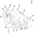
- FIG 4 shows a modification of the charging socket Figure 1 from the inside of the vehicle, i.e. with a view of the rear.
- the same reference numerals are used for the same components as in the first embodiment, different parts are given different reference numerals.
- the modification in the Figures 4 and 5 relates essentially to the structure of the flaps 16 and 18.
- the flaps consist of two angled walls.
- the flap 18 has a base wall 20 and a rear wall 24.
- the webs 32b and 32c can be seen between the rear wall 24 and the base wall 20.
- the difference consists in an additional base plate 21 which connects to the opening 14.
- the bottom plate 21 has slots suitable for the webs 32.
- Another difference is the side walls 23 and 29. These side walls are not connected to the flaps 16 or 18, but are formed as part of the frame. Accordingly, the side walls on the flaps 16 and 18 are omitted.
- a particular advantage of the variant from FIG Figures 4 and 5 consists in the fact that forces acting on the base plates 21 do not exert a torque on the flaps 16, 18 and thus do not cause the flaps to open contribute.
- the flaps 16, 18 are equipped with seals 31, 33, which ensure additional tightness when closed.
- FIG. 3 shows a third embodiment having a locking mechanism 50.
- the locking mechanism 50 is arranged on both sides of the flaps 16 and 18.
- the locking mechanism 50 has an unlocking lever 52 which projects into the opening 14 between the side walls 26 and 28.
- the release lever 52 is connected to a shaft 54 in a rotationally fixed manner.
- the shaft 54 is arranged in two bearing sections 56 and 58 on the rear side of the frame 12.
- Unlocking hooks 60, 62 are provided at the end of shaft 54.
- the unlocking hooks 60, 62 have a projection 64 at their free end, which is connected to a spring element 66.
- the other end of the spring element 66 is connected to a projection 64 'on the opposite locking lever 60'.
- Each of the flaps 16, 18 has a pretensioning spring element 68, 70 with which the flaps 16, 18 are pretensioned into their closed position.
- Figure 6 shows a position of the release levers 60, 62, 60 ', 62' in which the end of the release lever rests on the respective flap 16, 18.
- the flap cannot be swung open and is blocked by the release lever.
- the shaft 54 is rotated and the unlocking levers 60, 62, 60 ', 62' are spread open against the spring force 66 and the flaps 16, 18 can be pivoted open against the spring force 68, 70.
- the process of pivoting open takes place via a series of webs which are arranged in the interior of the flaps 16, 18 and, for example, in Figure 7 can be recognized.
Landscapes
- Engineering & Computer Science (AREA)
- Chemical & Material Sciences (AREA)
- Combustion & Propulsion (AREA)
- Transportation (AREA)
- Mechanical Engineering (AREA)
- Life Sciences & Earth Sciences (AREA)
- Sustainable Development (AREA)
- Sustainable Energy (AREA)
- Electric Propulsion And Braking For Vehicles (AREA)
- Connector Housings Or Holding Contact Members (AREA)
- Arrangement Or Mounting Of Propulsion Units For Vehicles (AREA)
Abstract
Description
- Die vorliegende Erfindung betrifft eine Ladebuchse für einen elektrischen Steckverbinder an einem Fahrzeug, insbesondere an einem Flurförderzeug. Bei elektrisch betriebenen Fahrzeugen besteht die Möglichkeit, diese extern nachzuladen, ohne dass die Batterie vom Fahrzeug entfernt werden muss. Hierzu ist eine am Fahrzeug montierte Ladebuchse vorgesehen, die beispielsweise einen am Fahrzeug mitgeführten elektrischen Steckverbinder besitzt. Über die Ladebuchse wird mit einem externen Ladestecker eine elektrisch leitende Verbindung zu dem Steckverbinder des Fahrzeugs hergestellt, um beispielsweise elektrische Leistung und Daten mit diesem austauschen zu können.
- Bei Fahrzeugen, insbesondere bei Flurförderzeugen, die auch rauen Arbeits- und Einsatzbedingungen ausgesetzt sind besteht die Notwendigkeit, den elektrischen Steckverbinder in der Ladebuchse zu schützen. Hierzu sind eine Reihe von Konzepten bekannt. Die Ladebuchse kann hinter einer aufklappbaren Tür angeordnet sein, die durch Betätigung eines Öffnungsmechanismus geöffnet werden kann. Nachteilig an dieser Lösung ist, dass Schwenkraum für die aufklappbare Tür vorgesehen sein muss.
- Alternativ sind Ladebuchsen bekannt, die eine oder mehrere kleine federbelastete und nach innen öffnende Klappen aufweisen. Der Batteriestecker wird mit etwas Kraft durch die entstehende Öffnung gedrückt. Nachteilig an dieser Lösung ist, dass die federbelasteten Klappen möglicherweise bei der Reinigung mit einem Druckluftoder Wasserstrahl öffnen und die elektrischen Kontakte in der Ladebuchse nicht ausreichend geschützt sind.
- Den Nachteil überwindet eine Ladebuchse mit einer federbelasteten Klappe, die nach außen aufgeklappt werden kann. Hierdurch wird allerdings der Zugang zur Ladebuchse und ihren elektrischen Kontakten am Fahrzeug erschwert.
- Aus
DE 10 2015 109 081 A1 ist ein Flurförderzeug mit einer Ladesteckerverbindung bekannt geworden, bei der mindestens eine Ladeklappe vorgesehen ist, bei der die mindestens eine Ladeklappe nach innen gedrückt wird, wenn der Ladestecker in die Ladebuchse eingeführt wird. - Aus
DE 2011 006 473 A1 ist eine Ladeeinrichtung mit Lamellenverschluss für ein Elektrofahrzeug bekannt geworden. Hierbei ist auch eine Ausgestaltung vorgesehen, bei der vorgespannte Lamellen vorgesehen sind, die um zwei parallel zueinander angeordnete Achsen verschwenkbar sind. Beim Einführen eines Ladesteckers schwenken diese nach innen auf und verschwenken bei Entfernen des Ladesteckers in ihre angeschlossene Position. - Der Erfindung liegt die Aufgabe zu Grunde eine Ladebuchse bereitzustellen, die bei möglichst gutem Bedienungskomfort einen wirksamen Schutz gegen ein unbeabsichtigtes Öffnen der Ladeklappe bietet.
- Erfindungsgemäß wird die Aufgabe durch eine Ladebuchse mit den Merkmalen aus Anspruch 1 gelöst. Vorteilhafte Ausgestaltungen bilden die Gegenstände der Unteransprüche.
- Erfindungsgemäß ist eine Ladebuchse mit einem elektrischen Steckverbinder für einen Ladestecker vorgesehen. Die Ladebuchse kann hierbei einteilig mit dem elektrischen Steckverbinder ausgebildet sein oder der elektrische Steckverbinder ist an der Ladebuchse montiert. Zur besseren Unterscheidung wird nachfolgend ein elektrischer Steckverbinder als der fahrzeugseitige Teil an der elektrischen Steckverbindung bezeichnet, während für extern von einem Ladestecker gesprochen wird. Die erfindungsgemäße Buchse besitzt einen Rahmen mit einer Öffnung zu dem elektrischen Steckverbinder und ein Paar von schwenkbar an parallel zueinander verlaufenden Schwenkachsen angeordneten Klappen. Mindestens ein Federelement spannt die Klappen in eine geschlossene Position vor. Bei der erfindungsgemäßen Ladebuchse öffnen die Klappen nach innen durch Einführen des Ladesteckers in die Öffnung in dem Rahmen der Ladebuchse. Erfindungsgemäß ist vorgesehen, dass jede der Klappen eine Grundwand und eine Rückwand aufweist. Im geschlossenen Zustand sind die Rückwände erfindungsgemäß gegenüber einer gedachten Ebene der Öffnung versetzt. Der Versatz der Rückwand erfolgt dabei in Richtung des elektrischen Steckverbinders, also in Richtung Fahrzeuginnenraum bei einer in einem Fahrzeug montierten Ladebuchse. Ein auf die Ladebuchse gerichteter Druckluft- oder Wasserstrahl trifft, wenn er auf die Öffnung der Ladebuchse gerichtet ist im Wesentlichen auf die zurückversetzten Rückwände der Klappen, wodurch ein die Klappe öffnendes Moment vermieden oder deutlich reduziert werden kann. Als besonders vorteilhaft hat es sich herausgestellt, wenn der Versatz (V) der Rückwand 0,5 bis 10 cm und besonders bevorzugt 1 bis 6 cm beträgt. Ebenso hat es sich als zweckmäßig herausgestellt einen Versatz (V) für die Rückwand auf eine Öffnungshöhe (H) zu beziehen, wobei bevorzugt 0,1 H ≤ V ≤ 2 H und insbesondere 0,4 H ≤ V ≤ 1 H gewählt werden kann. Anders als bei Klappen aus dem Stand der Technik ist die erfindungsgemäße Klappe mit zwei Wandabschnitten aufgebaut, der Grundwand und der jeweiligen Rückwand. Angreifende Kräfte greifen daher hauptsächlich an der Rückwand und nur teilweise an der Grundwand an. Durch die Zwischenschaltung der Grundwand entsteht der Versatz der Rückwände und das öffnende Drehmoment von der Rückwand auf die Klappe wird insgesamt reduziert.
- Bevorzugt ist ein parallel zur Schenkachs verlaufender Knick zwischen den beiden Wandabschnitten vorgesehen. Die Orientierung des Knicks parallel zur Schwenkachse stellt sicher, dass im Wesentlichen die versetzt angeordnete Rückwand die Öffnung verschließt. Bevorzugt schließen die Grundwand und ihre jeweilige Rückwand einen rechten oder einen stumpfen Winkel miteinander ein, hierdurch wird die Bildung einer "Tasche" oder einer Aufnahme zwischen Grundund Rückwand vermieden, in der sich Wasser oder Druckluft sammeln könnte.
- In einer bevorzugten Weiterbildung der erfindungsgemäßen Ladebuchse ist das mindestens eine Federelement an beiden Klappen angebracht und spannt diese in die geschlossene Stellung vor. Durch die Anbringung des Federelements an den beiden Klappen wird Bauraum für die Ladebuchse im Fahrzeuginnenraum gespart. Das mindestens eine Federelement kann platzsparend an den beiden Klappen angeordnet sein und diese gegeneinander in die geschlossene Position vorspannen.
- Bevorzugt verläuft das mindestens eine Federelement senkrecht zur Schwenkachse, wobei weiter bevorzugt die Rückwand im Wesentlichen parallel zu dem mindestens einem Federelement verläuft. Durch die Anordnung des Federelements senkrecht zur Schwenkachse wird einem Aufschwenken der beiden Klappen eine maximale Kraft des Federelements entgegengesetzt.
- In einer weiter bevorzugten Ausgestaltung weist mindestens eine der Grundwände eine oder mehrere Durchbrechungen auf, wodurch beispielsweise Wasser oder Druckluft, die durch die Öffnung im Rahmen in einen von Grund- und Rückwand gebildeten Raum der Ladebuchse eingetreten ist, entweichen kann. Die elektrische Steckverbindung ist hierbei durch die Rückwand geschützt.
- In einer besonders bevorzugten Ausgestaltung der erfindungsgemäßen Ladebuchse ist jede Klappe mit mindestens einem Steg ausgestattet, der sich von der Schwenkachse ausgehend in Richtung Rückwand erstreckt, wobei ein Abstand zwischen den gegenüberliegenden Stegen beider Klappen sich hin zur Rückwand verjüngt. Durch den sich verjüngenden Abstand werden die Klappen durch einen eingeführten Ladestecker geöffnet. Die Stege selbst erstrecken sich scheibenförmig in Richtung von der Schwenkachse zur Rückwand, so dass ein angreifender Wasseroder Druckluftstrahl keine Angriffsfläche an dem Steg besitzt.
- In einer bevorzugten Ausgestaltung ist der Rahmen der Ladebuchse mit einer rechteckigen Öffnung ausgestattet, die durch die beiden Klappen verschlossen wird. Die rechteckige Öffnung ist bevorzugt mindestens doppelt so lang in einer ersten Richtung wie in einer zweiten Richtung. Die Schwenkachsen erstrecken sich jeweils bevorzugt in der ersten Richtung in der Öffnung, also in der längeren Richtung.
- In einer bevorzugten weiteren Ausgestaltung der Erfindung ist ein Verriegelungsmechanismus für die beiden Klappen vorgesehen. Der Verriegelungsmechanismus besitzt mindestens einen auch in einer geschlossenen Position der beiden Klappen zugänglichen Entriegelungshebel. Die Klappen sind in der geschlossenen Position verriegelt und werden durch eine Betätigung eines Entriegelungshebels entriegelt. Der Entriegelungshebel oder die Entriegelungshebel werden bevorzugt betätigt, indem der Ladestecker in die Öffnung im Rahmen eingeführt wird und gegen den Entriegelungshebel drückt. Wird der Entriegelungshebel betätigt, so verschwenkt dieser und dreht mindestens einen Sperrhaken aus einer die Klappen sperrenden Position. Der mindestens eine Sperrhaken schwenkt gegen eine Federkraft auf und gibt die Klappen für ein Aufschwenken frei.
- Drei bevorzugte Ausführungsbeispiele der erfindungsgemäßen Ladebuchse werden anliegend näher beschrieben. Es zeigen:
- Figur 1
- eine perspektivische Ansicht auf den Rahmen mit geschlossenen Klappen einer ersten Ausführungsform,
- Figur 2a
- eine perspektivische Ansicht aus
Figur 1 bei einem ganz oder teilweise gesteckten Ladestecker, - Fig. 2b
- eine perspektivische Ansicht bei geschlossenen Klappen und einem Spritzschutz,
- Figur 3
- die Ladebuchse aus
Figur 1 zusammen mit einem noch nicht vollständig gesteckten Ladestecker und - Figur 4
- eine perspektivische Ansicht einer zweiten Ausführungsform in einer perspektivischen Ansicht bei teilweise geöffneten Klappen,
- Figur 5
- die Ausführungsform aus
Figur 4 bei geschlosssenen Klappen, - Figur 6
- eine dritte Ausführungsform mit einem Verriegelungsmechanismus und
- Figur 7
- die dritte Ausführungsform aus
Figur 6 in einer geschlossenen Position der Klappen. -
Figur 1 zeigt eine Ladebuchse in einer perspektivischen Ansicht. Zu einer besseren Übersicht ist die Ladebuchse in einem nicht am Fahrzeug montierten Zustand dargestellt. Die Ladebuchse 10 weist einen Montagerahmen 12 auf, der eine im Wesentlichen rechteckige Form mit abgerundeten Ecken besitzt. Der Montagerahmen 12 besitzt eine im Wesentlichen ebene Frontplatte 13, die beispielsweise in die Fahrzeugverkleidung eingelassen ist und bündig oder unter Bildung einer Fuge mit dieser abschließt. Der Rahmen besitzt eine erste Ausdehnung H und eine zweite Ausdehnung B, die mindestens doppelt so groß ist wie die Ausdehnung in Richtung H. - Zentral in dem Rahmen 12 angeordnet ist eine Öffnung 14, die ebenfalls eine rechteckige Form besitzt. Die Öffnung 14 ist durch Kanten begrenzt, die parallel zu den Außenkanten des Rahmens 12 und seiner Abdeckplatte 13 verlaufen. Das Verhältnis der Seitenlängen in der Öffnung 14 zueinander, entspricht ungefähr dem Verhältnis des Rahmens 12 an seinen Außenkanten.
- Deutlich zu erkennen in
Figur 1 ist die Situation, dass der Rahmen 12 mit seiner Öffnung 14 nicht bündig in der Ebene der Öffnung 14 durch die beiden Klappen 16, 18 abgeschlossen ist. Die Öffnung 14 wird durch zwei Klappen 16, 18 verschlossen, die nach Innen versetzt sind. Jede der Klappen 16, 18 besitzt eine Grundwand 20, zwei Seitenwände 22, 28 entlang der Breite B sowie jeweils eine Rückwand 24, 30. Die Rückwände 24 und 30 bilden einen Abschluss der Öffnung, der gegenüber der Öffnung 14 versetzt ist. Die Wände mit Grundwand und Rückwand treffen jeweils in einem Knick unter einem Winkel von 90° aufeinander, so dass jede Klappe mit ihren beiden Seitenwänden, der Grundwand und der Rückwand vier Seiten eines Quaders bildet. Zwischen Grundwand 20 und Rückwand 24 erstrecken sich mehrere dreieckige Streben 32a, b, c sowie 34a, b, c. Die Stege sind jeweils parallel zueinander angeordnet und jeweils einander gegenüberliegend. Der Abstand zwischen den (freien) Schenkeln an der Stege 32 und 34 verjüngt sich beginnend mit der Öffnung 14 in dem Rahmen 12 hin zu den Rückwänden 24 und 30 der Klappen. -
Figur 1 zeigt ferner schematisch dargestellt einen elektrischen Steckverbinder 36, der zusammen mit dem Montagerahmen 12 die Ladebuchse 10 bildet. -
Figur 2 zeigt eine perspektivische Ansicht aus der Sicht des Steckverbinders 36, also aus dem Inneren. Zu erkennen ist der Rahmen 12 mit der Öffnung 14. Eine untere Klappe 16 und die gegenüberliegende Klappe 18 ist in einer teilweise geöffneten Position dargestellt, in der die Klappen verschwenkt sind. Die Klappe 16 ist über eine Schwenkachse 38 an einem unteren Teil des Rahmens 12 angelenkt, während die obere Klappe 18 an einem oberen Teil des Rahmens 12 über eine Schwenkachse 40 angelenkt ist. -
Figur 2a zeigt ebenfalls den Aufbau der Klappen im Zusammenhang mit Grundwand und Rückwand. Die untere Klappe 16 besitzt eine im geschlossenen Zustand horizontal verlaufende Grundwand 20 und eine dazu senkrecht stehende Rückwand 24. Beide Wände treffen in einem 90° Winkel aufeinander. Grundsätzlich kann der Winkel (im mathematischen Drehsinn) auch größer sein als der dargestellte 90° Winkel. Ist der Winkel größer als 90°, so weist die Rückwand 16 vom Rahmen fort und nicht auf diesen oder seine Öffnung hin. - Der Rahmen 12 besitzt auf seiner der Frontplatte 13 gegenüberliegenden Seite einen umlaufenden Vorsprung, mit dem die Ladebuchse 10 beispielsweise in eine Verkleidung des Fahrzeugs eingesetzt werden kann. Zudem sind an dem sich in Richtung der Breite B erstreckende Kante des Rahmens, Rastvorsprünge 46a, 46b vorgesehen, mit denen der Rahmen 12 in ein Verkleidungs- oder Karosseriebauteil eingeclipst werden kann.
Figur 4 zeigt die Klappen 16 und 18 im geöffneten Zustand. Der Ladestecker 42 ist durch den Rahmen 12 hindurch in die elektrische Steckverbindung 36 eingeführt worden. Deutlich zu erkennen inFigur 4 ist das Federelement 44, das an der Außenwand der Seitenwände 22 und 28 von Klappen 16 bzw. 18 befestigt ist und diese in eine geschlossene Position vorspannt. - Ein besonderer Effekt wird durch die Anordnung der Rückwände 24 und 30 erzielt. Beide Rückwände sind gegenüber der vom Rahmen 12 aufgespannten Ebene der Öffnung 14 nach innen, hin zum elektrischen Steckverbinder 36 versetzt. Nimmt man nun an, dass beispielsweise ein Wasserstrahl oder ein Druckluftstrahl durch die Öffnung 14 auf die Klappen gerichtet wird, so ist eine von dem Wasserstrahl aufgebrachte Hebelkraft deutlich geringer als für eine Rückwand, die direkt an den Schwenkachsen 38 und 40 ansetzt. Die schwerer zu öffnenden Klappen 16 und 18 werden aber für den eingeführten Ladestecker 36 weiterhin ohne erhöhten Kraftaufwand geöffnet, in dem in die Stege 32a, b, c und 34a, b, c mithilfe des Ladesteckers 42 geöffnet werden.
- Für den Fall, dass die Ladebuchse 10 Druckwasserstrahl ausgesetzt ist, kann es vorteilhaft sein in den Grundwänden Durchbrechungen vorzusehen, durch die Flüssigkeit abfließen kann, ohne dass sie auf den elektrischen Steckverbinder trifft.
-
Fig. 2b zeigt einen weiteren möglichen Aufbau der Ladebuchse bei geschlossenen Klappen 16, 18. Dargestellt ist der Rahmen 12, der über seine Rastvorsprünge 46a, 46b montiert werden kann, beispielsweise in einer Ausnehmung der Fahrzeugverkleidung. Als Spritzschutz 17 ist ein weiterer Rahmen vorgesehen, der zur besseren Übersicht inFig. 2b geschnitten dargestellt ist. Der Rahmen 12 besteht aus einem L-förmigen Profil, das die Klappen 16, 18 gegenüber dem Innenraum verdeckt. Hierbei besitzt der Spritzschutz 17 zwei in einem rechten Winkel zueinander stehende Schenkel, von denen einer parallel zur Grundwand und einer parallel zur Rückwand angeordnet ist. Der Spritzschutz 17 ist so angeordnet, dass die Klappen 16, 18 geöffnet werden können. Je nach Ausgestaltung kann der Spritzschutz 17 beispielsweise noch mit einem Ablauf versehen sein. -
Figur 3 zeigt die Situation, wie ein Ladestecker 42 in die Öffnung 14 des Rahmens 12 eingeführt wird, um mit dem elektrischen Steckverbinder 36 eine elektrisch leitende Verbindung einzugehen. Wenn der Ladestecker 42 in Richtung des elektrischen Steckverbinders 36 vorgeschoben wird, kommt der Ladestecker 42 mit den Stegen 32 und 34 in Kontakt und die Klappen 16 und 18 werden aufgespreizt. Das Aufspreizen erfolgt gegen eine Federkraft eines (vom Rahmen verdeckten) Federelements. -
Figur 4 zeigt eine Abwandlung der Ladebuchse ausFigur 1 von der Fahrzeuginnenseite, also mit einem Blick auf ihre Rückseite. Es werden gleiche Bezugszeichen für gleiche Bauteile wie bei der ersten Ausführungsform verwendet, abweichende Teile erhalten abweichende Bezugszeichen. - Die Abwandlung in den
Figuren 4 und5 betrifft im Wesentlichen den Aufbau der Klappen 16 und 18. Wie inFigur 4 zu erkennen ist, bestehen die Klappen aus zwei angewinkelten Wänden. Die Klappe 18 besitzt eine Grundwand 20 und eine Rückwand 24. Zwischen Rückwand 24 und Grundwand 20 sind die Stege 32b und 32c zu erkennen. Der Unterschied besteht in einer zusätzlichen Bodenplatte 21, die an die Öffnung 14 anschließt. Die Bodenplatte 21 besitzt Schlitze, passend für die Stege 32. Ein weiterer Unterschied besteht in den Seitenwände 23 und 29. Diese Seitenwände sind nicht mit den Klappen 16 oder 18 verbunden, sondern als Teil des Rahmens geformt. Dementsprechend entfallen die Seitenwände an den Klappen 16 und 18. Ein besonderer Vorteil der Ausführungsvariante aus denFiguren 4 und5 besteht darin, dass auf die Bodenplatten 21 wirkende Kräfte nicht ein Drehmoment auf die Klappen 16, 18 ausüben und somit nicht zu einem Öffnen der Klappen beitragen. Zudem sind die Klappen 16, 18 mit Dichtungen 31, 33 ausgestattet, die im geschlossenen Zustand für zusätzliche Dichtigkeit sorgen. -
Figur 6 zeigt eine dritte Ausführungsform, die einen Verriegelungsmechanismus 50 besitzt. Der Verriegelungsmechanismus 50 ist an beiden Seiten der Klappen 16 und 18 angeordnet. Der Verriegelungsmechanismus 50 weist einen Entriegelungshebel 52 auf, der zwischen den Seitenwänden 26 und 28 in die Öffnung 14 vorsteht. Der Entriegelungshebel 52 ist drehfest mit einer Welle 54 verbunden. Die Welle 54 ist in zwei Lagerabschnitten 56 und 58 auf der Rückseite des Rahmens 12 angeordnet. Endseitig der Welle 54 sind Entriegelungshaken 60, 62 vorgesehen. Die Entriegelungshaken 60, 62 besitzen an ihrem freien Ende einen Vorsprung 64, der mit einem Federelement 66 verbunden ist. Das andere Ende des Federelements 66 ist mit einem Vorsprung 64' an dem gegenüberliegenden Verriegelungshebel 60' verbunden. - Jede der Klappen 16, 18 besitzt ein vorspannendes Federelement 68, 70, mit dem die Klappen 16, 18 in ihre geschlossene Position vorgespannt sind.
-
Figur 6 zeigt eine Position der Entriegelungshebel 60, 62, 60', 62', in der das Ende der Entriegelungshebel an der jeweiligen Klappe 16, 18 anliegt. Ein Aufschwenken der Klappe ist nicht möglich und wird durch die Entriegelungshebel blockiert. Durch ein Betätigen des Entriegelungshebels 52 wird die Welle 54 gedreht und die Entriegelungshebel 60, 62, 60', 62' werden gegen die Federkraft 66 aufgespreizt und die Klappen 16, 18 können gegen die Federkraft 68, 70 aufgeschwenkt werden. Der Vorgang des Aufschwenkens erfolgt ebenso wie in den obigen Ausführungsbeispielen 3 über eine Reihe von Stegen, die im Inneren der Klappen 16, 18 angeordnet sind und beispielsweise inFigur 7 zu erkennen sind. -
- 10
- Ladebuchse
- 12
- Montagerahmen
- 13
- Frontplatte
- 14
- Öffnung
- 16
- Klappe
- 17
- Spritzschutz
- 18
- Klappe
- 20
- Grundwand
- 21
- Bodenplatte
- 22
- Seitenwand
- 23
- Seitenwand
- 24
- Rückwand
- 28
- Seitenwand
- 29
- Seitenwand
- 30
- Rückwand
- 31
- Dichtung
- 32a
- Steg
- 32b
- Steg
- 32c
- Steg
- 33
- Dichtung
- 34a
- Steg
- 34b
- Steg
- 34c
- Steg
- 36
- Steckverbinder
- 38
- Schwenkachse
- 40
- Schwenkachse
- 42
- Ladestecker
- 44
- Vorsprung
- 46a
- Rastvorsprung
- 46b
- Rastvorsprung
- 50
- Verriegelungsmechanismus
- 52
- Entriegelungshebel
- 54
- Welle
- 56
- Lagerabschnitt
- 58
- Lagerabschnitt
- 60
- Entriegelungshaken
- 60'
- Entriegelungshaken
- 62
- Entriegelungshaken
- 62'
- Entriegelungshaken
- 64
- Vorsprung
- 64'
- Vorsprung
- 66
- Federelement
- 68
- Federkraft
- 70
- Federkraft
Claims (14)
- Ladebuchse (10) mit einem elektrischen Steckverbinder (36) für einen Ladestecker (42), die einen Rahmen (12) mit einer Öffnung (14) zu dem elektrischen Steckverbinder (36) und ein Paar von schwenkbar an parallel zu einander verlaufenden Schwenkachsen (38, 40) angeordneten Klappen (16, 18) aufweist, wobei mindestens ein Federelement die Klappen (16, 18) in eine geschlossene Position vorspannt, dadurch gekennzeichnet, dass jede Klappe (16, 18) eine Grundwand (20) und eine Rückwand (24, 30) aufweist, wobei die Rückwände (24, 30) gegenüber einer gedachten Ebene der Öffnung (14) im Rahmen (12) in Richtung des elektrischen Steckverbinders versetzt sind.
- Ladebuchse nach Anspruch 1, dadurch gekennzeichnet, dass jede Klappe einen parallel zu der Schenkachse (38, 40) verlaufenden Knick zwischen der Grundwand (20) und der Rückwand (24, 30) besitzt.
- Ladebuchse nach Anspruch 2, dadurch gekennzeichnet, dass der Knick zwischen Grundwand (20) und jeweiliger Rückwand (24, 30) einen rechten oder einen stumpfen Winkel einschließt.
- Ladebuchse (10) nach einem der Ansprüche 1 bis 3, dadurch gekennzeichnet, dass mindestens ein Federelement an beiden Klappen (16, 18) angebracht ist und diese in ihre geschlossene Stellung vorspannt.
- Ladebuchse (10) nach einem der Ansprüche 1 bis 4, dadurch gekennzeichnet, dass mindestens ein Federelement senkrecht zur Schwenkachse (38, 40) steht.
- Ladebuchse (10) nach einem der Ansprüche 1 bis 5, dadurch gekennzeichnet, dass die Rückwand (24, 30) im Wesentlichen parallel zu dem mindestens einen Federelement verläuft.
- Ladebuchse (10) nach Anspruch 6, dadurch gekennzeichnet, dass die Grundwand (20) sich von der Schwenkachse (38, 40) zu der Rückwand (24, 30) erstreckt.
- Ladebuchse (10) nach Anspruch 7, dadurch gekennzeichnet, dass mindestens eine der Grundwände (20) eine oder mehrere Durchbrechungen aufweist.
- Ladebuchse (10) nach Anspruch 7 oder 8, dadurch gekennzeichnet, dass jede Klappe (16, 18) mindestens einen Steg (32a, 32b, 32c, 34a, 34b, 34c) aufweist, der sich von der Schwenkachse (38, 40) ausgehend in Richtung Rückwand (24, 30) erstreckt, wobei der Abstand zwischen gegenüberliegenden Stegen (32a, 32b, 32c, 34a, 34b, 34c) der beiden Klappen (16, 18) hin zu der Rückwand (24, 30) sich verjüngt.
- Ladebuchse (10) nach einem der Ansprüche 1 bis 9, dadurch gekennzeichnet, dass der Rahmen (12) eine rechteckige Öffnung (14) umgibt, die durch die beiden Klappen (16, 18) verschlossen wird.
- Ladebuchse (10) nach Anspruch 8, dadurch gekennzeichnet, dass die rechteckige Öffnung (14) sich mehr als doppelt so viel in eine erste Richtung erstreckt wie in eine zweite Richtung.
- Ladebuchse (10) nach Anspruch 11, dadurch gekennzeichnet, dass die Schwenkachsen (38, 40) sich jeweils in die erste Richtung erstrecken.
- Ladebuchse (10) nach einem der vorhergehenden Ansprüche, dadurch gekennzeichnet, dass ein Verriegelungsmechanismus für die beiden Klappen (16, 18) vorgesehen ist, der einen oder mehrere auch bei geschlossener Position der beiden Klappen (16, 18) zugängliche mehrere Entriegelungshebel (52) aufweist, wobei die Klappen (16, 18) in der geschlossenen Position verriegelt sind bis der oder die Entriegelungshebel (52) betätigt wurde.
- Ladebuchse nach Anspruch 13, dadurch gekennzeichnet, dass der oder die Entriegelungshebel (52) über eine Welle (54) mindestens einen Sperrhaken (60, 62) gegen eine Federkraft (66) aus einer die Klappen (16, 18) sperrenden Position verschwenkt.
Applications Claiming Priority (1)
| Application Number | Priority Date | Filing Date | Title |
|---|---|---|---|
| DE102019115862.1A DE102019115862A1 (de) | 2019-06-11 | 2019-06-11 | Ladebuchse |
Publications (2)
| Publication Number | Publication Date |
|---|---|
| EP3750731A1 true EP3750731A1 (de) | 2020-12-16 |
| EP3750731B1 EP3750731B1 (de) | 2023-07-05 |
Family
ID=70553861
Family Applications (1)
| Application Number | Title | Priority Date | Filing Date |
|---|---|---|---|
| EP20172925.8A Active EP3750731B1 (de) | 2019-06-11 | 2020-05-05 | Ladebuchse |
Country Status (2)
| Country | Link |
|---|---|
| EP (1) | EP3750731B1 (de) |
| DE (1) | DE102019115862A1 (de) |
Cited By (3)
| Publication number | Priority date | Publication date | Assignee | Title |
|---|---|---|---|---|
| CN113593132A (zh) * | 2021-07-29 | 2021-11-02 | 浙江惺睿科技有限公司 | 一种共享充电宝 |
| CN114161974A (zh) * | 2021-12-10 | 2022-03-11 | 李龙勃 | 一种新能源电动汽车充电插头 |
| CN115084918A (zh) * | 2021-03-10 | 2022-09-20 | 保时捷股份公司 | 用于机动车辆的充电翻盖组件 |
Families Citing this family (2)
| Publication number | Priority date | Publication date | Assignee | Title |
|---|---|---|---|---|
| DE102023121377A1 (de) * | 2023-08-10 | 2025-02-13 | Iventum Gmbh | Micro IP-Verschluss, insbesondere USB-Anschlussbuchse |
| US20260074462A1 (en) | 2024-09-11 | 2026-03-12 | GM Global Technology Operations LLC | Automatic dust cap for auxiliary power outlet |
Citations (10)
| Publication number | Priority date | Publication date | Assignee | Title |
|---|---|---|---|---|
| DE495191C (de) * | 1928-05-17 | 1930-04-03 | Charles Leonard Arnold | Beruehrungsschutzvorrichtung fuer Steckdosen u. dgl. |
| US4176897A (en) * | 1976-11-19 | 1979-12-04 | Bunker Ramo Corporation | EMI protected connector assembly |
| JPH118005A (ja) * | 1997-06-16 | 1999-01-12 | Yazaki Corp | 開閉扉付き電気コネクタ |
| EP1139128A2 (de) * | 2000-03-24 | 2001-10-04 | Tyco Electronics Corporation | Abgeschirmter optischer Stecker |
| DE102011006473A1 (de) | 2011-03-31 | 2012-10-04 | Kiekert Ag | Ladeeinrichtung mit Lamellenverschluss für ein Elektrofahrzeug |
| DE102011082355B3 (de) * | 2011-09-08 | 2012-11-29 | Faurecia Innenraum Systeme Gmbh | Steckdose |
| US20140094045A1 (en) * | 2011-06-02 | 2014-04-03 | Yazaki Corporation | Connector |
| WO2014114374A1 (en) * | 2013-01-24 | 2014-07-31 | Dellner Components Sp.Z.O.O | A coupling means for electrically connecting a head-block to a spreader in a container-lifting arrangement. |
| US20160104962A1 (en) * | 2014-10-14 | 2016-04-14 | Hyundai Motor Company | Connector device |
| DE102015109081A1 (de) | 2015-06-09 | 2016-12-15 | Linde Material Handling Gmbh | Flurförderzeug mit Ladesteckerverbindung |
Family Cites Families (3)
| Publication number | Priority date | Publication date | Assignee | Title |
|---|---|---|---|---|
| JP2002343494A (ja) * | 2001-05-16 | 2002-11-29 | Sony Corp | 電気的接続装置および電気的接続装置を有する電子機器 |
| JP5779079B2 (ja) * | 2011-12-07 | 2015-09-16 | 日本航空電子工業株式会社 | コネクタ |
| US9975440B1 (en) * | 2017-05-04 | 2018-05-22 | Ford Global Technologies, Llc | Charge port covering assembly and method |
-
2019
- 2019-06-11 DE DE102019115862.1A patent/DE102019115862A1/de not_active Withdrawn
-
2020
- 2020-05-05 EP EP20172925.8A patent/EP3750731B1/de active Active
Patent Citations (10)
| Publication number | Priority date | Publication date | Assignee | Title |
|---|---|---|---|---|
| DE495191C (de) * | 1928-05-17 | 1930-04-03 | Charles Leonard Arnold | Beruehrungsschutzvorrichtung fuer Steckdosen u. dgl. |
| US4176897A (en) * | 1976-11-19 | 1979-12-04 | Bunker Ramo Corporation | EMI protected connector assembly |
| JPH118005A (ja) * | 1997-06-16 | 1999-01-12 | Yazaki Corp | 開閉扉付き電気コネクタ |
| EP1139128A2 (de) * | 2000-03-24 | 2001-10-04 | Tyco Electronics Corporation | Abgeschirmter optischer Stecker |
| DE102011006473A1 (de) | 2011-03-31 | 2012-10-04 | Kiekert Ag | Ladeeinrichtung mit Lamellenverschluss für ein Elektrofahrzeug |
| US20140094045A1 (en) * | 2011-06-02 | 2014-04-03 | Yazaki Corporation | Connector |
| DE102011082355B3 (de) * | 2011-09-08 | 2012-11-29 | Faurecia Innenraum Systeme Gmbh | Steckdose |
| WO2014114374A1 (en) * | 2013-01-24 | 2014-07-31 | Dellner Components Sp.Z.O.O | A coupling means for electrically connecting a head-block to a spreader in a container-lifting arrangement. |
| US20160104962A1 (en) * | 2014-10-14 | 2016-04-14 | Hyundai Motor Company | Connector device |
| DE102015109081A1 (de) | 2015-06-09 | 2016-12-15 | Linde Material Handling Gmbh | Flurförderzeug mit Ladesteckerverbindung |
Cited By (3)
| Publication number | Priority date | Publication date | Assignee | Title |
|---|---|---|---|---|
| CN115084918A (zh) * | 2021-03-10 | 2022-09-20 | 保时捷股份公司 | 用于机动车辆的充电翻盖组件 |
| CN113593132A (zh) * | 2021-07-29 | 2021-11-02 | 浙江惺睿科技有限公司 | 一种共享充电宝 |
| CN114161974A (zh) * | 2021-12-10 | 2022-03-11 | 李龙勃 | 一种新能源电动汽车充电插头 |
Also Published As
| Publication number | Publication date |
|---|---|
| DE102019115862A1 (de) | 2020-12-17 |
| EP3750731B1 (de) | 2023-07-05 |
Similar Documents
| Publication | Publication Date | Title |
|---|---|---|
| EP3750731B1 (de) | Ladebuchse | |
| DE102018128972B4 (de) | Klappe mit Öffnungsmechanismus | |
| DE19642687C2 (de) | Verriegelungsvorrichtung zur Absicherung einer Ladesteckdose | |
| EP2646277A2 (de) | Ladeschnittstelle für ein elektrofahrzeug | |
| DE2205011B2 (de) | Abdeckvorrichtung für die Frontfläche einer elektrischen Steckdose | |
| WO2012034638A1 (de) | Kraftfahrzeugladevorrichtung | |
| EP4230471A1 (de) | Fahrzeug, insbesondere elektrisch antreibbares fahrzeug | |
| DE10117173B4 (de) | Tür | |
| WO2015176714A1 (de) | Kraftfahrzeugtürschloss | |
| DE102017222061A1 (de) | Ladeklappenvorrichtung | |
| DE69523579T2 (de) | Gehäuse für ein elektrisches Gerät | |
| EP0969171B1 (de) | Abdeckung | |
| EP3616967B1 (de) | Fahrzeugbedienvorrichtung sowie verfahren zum ändern des anzeigewinkels einer bedien- und anzeigeeinrichtung einer derartigen fahrzeugbedienvorrichtung | |
| DE20221894U1 (de) | Elektrischer Steckverbinder | |
| EP2853664B1 (de) | Türgriff | |
| EP0295530B1 (de) | Anschlagpufferanordnung für schwenkbare Karosserieteile | |
| DE19601231A1 (de) | Elektrisches Hörgerät mit multifunktioneller Audioklappe | |
| DE202011000739U1 (de) | Steckverbindungsanordnung für elektrische Leiter | |
| WO2023117231A1 (de) | Fahrzeug mit einem verstaufach | |
| DE102006053477C5 (de) | Steckdose | |
| DE10036398A1 (de) | Vorrichtung zur Arretierung eines Schließzylindergehäuses | |
| EP1835580B1 (de) | Kabelverteilerschrank mit Berstsicherung | |
| DE69700929T2 (de) | Befestigung für ein Gehäuse, insbesondere zur Aufnahme elektrischer Geräte | |
| DE102019002900A1 (de) | Flügelelementöffnungsvorrichtung sowie Fahrzeug | |
| EP2947223B1 (de) | Wohndachfensterschwenkgriffanordnung, Wohndachfenster mit einer Wohndachfensterschwenkgriffanordnung sowie Verfahren zum Montieren eines Wohndachfensters |
Legal Events
| Date | Code | Title | Description |
|---|---|---|---|
| PUAI | Public reference made under article 153(3) epc to a published international application that has entered the european phase |
Free format text: ORIGINAL CODE: 0009012 |
|
| STAA | Information on the status of an ep patent application or granted ep patent |
Free format text: STATUS: THE APPLICATION HAS BEEN PUBLISHED |
|
| AK | Designated contracting states |
Kind code of ref document: A1 Designated state(s): AL AT BE BG CH CY CZ DE DK EE ES FI FR GB GR HR HU IE IS IT LI LT LU LV MC MK MT NL NO PL PT RO RS SE SI SK SM TR |
|
| AX | Request for extension of the european patent |
Extension state: BA ME |
|
| STAA | Information on the status of an ep patent application or granted ep patent |
Free format text: STATUS: REQUEST FOR EXAMINATION WAS MADE |
|
| 17P | Request for examination filed |
Effective date: 20210614 |
|
| RBV | Designated contracting states (corrected) |
Designated state(s): AL AT BE BG CH CY CZ DE DK EE ES FI FR GB GR HR HU IE IS IT LI LT LU LV MC MK MT NL NO PL PT RO RS SE SI SK SM TR |
|
| STAA | Information on the status of an ep patent application or granted ep patent |
Free format text: STATUS: EXAMINATION IS IN PROGRESS |
|
| 17Q | First examination report despatched |
Effective date: 20220209 |
|
| GRAP | Despatch of communication of intention to grant a patent |
Free format text: ORIGINAL CODE: EPIDOSNIGR1 |
|
| STAA | Information on the status of an ep patent application or granted ep patent |
Free format text: STATUS: GRANT OF PATENT IS INTENDED |
|
| INTG | Intention to grant announced |
Effective date: 20230201 |
|
| GRAS | Grant fee paid |
Free format text: ORIGINAL CODE: EPIDOSNIGR3 |
|
| GRAA | (expected) grant |
Free format text: ORIGINAL CODE: 0009210 |
|
| STAA | Information on the status of an ep patent application or granted ep patent |
Free format text: STATUS: THE PATENT HAS BEEN GRANTED |
|
| AK | Designated contracting states |
Kind code of ref document: B1 Designated state(s): AL AT BE BG CH CY CZ DE DK EE ES FI FR GB GR HR HU IE IS IT LI LT LU LV MC MK MT NL NO PL PT RO RS SE SI SK SM TR |
|
| REG | Reference to a national code |
Ref country code: CH Ref legal event code: EP |
|
| REG | Reference to a national code |
Ref country code: AT Ref legal event code: REF Ref document number: 1584541 Country of ref document: AT Kind code of ref document: T Effective date: 20230715 |
|
| REG | Reference to a national code |
Ref country code: DE Ref legal event code: R096 Ref document number: 502020004002 Country of ref document: DE |
|
| P01 | Opt-out of the competence of the unified patent court (upc) registered |
Effective date: 20230628 |
|
| REG | Reference to a national code |
Ref country code: IE Ref legal event code: FG4D Free format text: LANGUAGE OF EP DOCUMENT: GERMAN |
|
| REG | Reference to a national code |
Ref country code: LT Ref legal event code: MG9D |
|
| REG | Reference to a national code |
Ref country code: NL Ref legal event code: MP Effective date: 20230705 |
|
| PG25 | Lapsed in a contracting state [announced via postgrant information from national office to epo] |
Ref country code: NL Free format text: LAPSE BECAUSE OF FAILURE TO SUBMIT A TRANSLATION OF THE DESCRIPTION OR TO PAY THE FEE WITHIN THE PRESCRIBED TIME-LIMIT Effective date: 20230705 |
|
| PG25 | Lapsed in a contracting state [announced via postgrant information from national office to epo] |
Ref country code: GR Free format text: LAPSE BECAUSE OF FAILURE TO SUBMIT A TRANSLATION OF THE DESCRIPTION OR TO PAY THE FEE WITHIN THE PRESCRIBED TIME-LIMIT Effective date: 20231006 |
|
| PG25 | Lapsed in a contracting state [announced via postgrant information from national office to epo] |
Ref country code: ES Free format text: LAPSE BECAUSE OF FAILURE TO SUBMIT A TRANSLATION OF THE DESCRIPTION OR TO PAY THE FEE WITHIN THE PRESCRIBED TIME-LIMIT Effective date: 20230705 |
|
| PG25 | Lapsed in a contracting state [announced via postgrant information from national office to epo] |
Ref country code: IS Free format text: LAPSE BECAUSE OF FAILURE TO SUBMIT A TRANSLATION OF THE DESCRIPTION OR TO PAY THE FEE WITHIN THE PRESCRIBED TIME-LIMIT Effective date: 20231105 |
|
| PG25 | Lapsed in a contracting state [announced via postgrant information from national office to epo] |
Ref country code: SE Free format text: LAPSE BECAUSE OF FAILURE TO SUBMIT A TRANSLATION OF THE DESCRIPTION OR TO PAY THE FEE WITHIN THE PRESCRIBED TIME-LIMIT Effective date: 20230705 Ref country code: RS Free format text: LAPSE BECAUSE OF FAILURE TO SUBMIT A TRANSLATION OF THE DESCRIPTION OR TO PAY THE FEE WITHIN THE PRESCRIBED TIME-LIMIT Effective date: 20230705 Ref country code: PT Free format text: LAPSE BECAUSE OF FAILURE TO SUBMIT A TRANSLATION OF THE DESCRIPTION OR TO PAY THE FEE WITHIN THE PRESCRIBED TIME-LIMIT Effective date: 20231106 Ref country code: NO Free format text: LAPSE BECAUSE OF FAILURE TO SUBMIT A TRANSLATION OF THE DESCRIPTION OR TO PAY THE FEE WITHIN THE PRESCRIBED TIME-LIMIT Effective date: 20231005 Ref country code: LV Free format text: LAPSE BECAUSE OF FAILURE TO SUBMIT A TRANSLATION OF THE DESCRIPTION OR TO PAY THE FEE WITHIN THE PRESCRIBED TIME-LIMIT Effective date: 20230705 Ref country code: LT Free format text: LAPSE BECAUSE OF FAILURE TO SUBMIT A TRANSLATION OF THE DESCRIPTION OR TO PAY THE FEE WITHIN THE PRESCRIBED TIME-LIMIT Effective date: 20230705 Ref country code: IS Free format text: LAPSE BECAUSE OF FAILURE TO SUBMIT A TRANSLATION OF THE DESCRIPTION OR TO PAY THE FEE WITHIN THE PRESCRIBED TIME-LIMIT Effective date: 20231105 Ref country code: HR Free format text: LAPSE BECAUSE OF FAILURE TO SUBMIT A TRANSLATION OF THE DESCRIPTION OR TO PAY THE FEE WITHIN THE PRESCRIBED TIME-LIMIT Effective date: 20230705 Ref country code: GR Free format text: LAPSE BECAUSE OF FAILURE TO SUBMIT A TRANSLATION OF THE DESCRIPTION OR TO PAY THE FEE WITHIN THE PRESCRIBED TIME-LIMIT Effective date: 20231006 Ref country code: FI Free format text: LAPSE BECAUSE OF FAILURE TO SUBMIT A TRANSLATION OF THE DESCRIPTION OR TO PAY THE FEE WITHIN THE PRESCRIBED TIME-LIMIT Effective date: 20230705 Ref country code: ES Free format text: LAPSE BECAUSE OF FAILURE TO SUBMIT A TRANSLATION OF THE DESCRIPTION OR TO PAY THE FEE WITHIN THE PRESCRIBED TIME-LIMIT Effective date: 20230705 |
|
| PG25 | Lapsed in a contracting state [announced via postgrant information from national office to epo] |
Ref country code: PL Free format text: LAPSE BECAUSE OF FAILURE TO SUBMIT A TRANSLATION OF THE DESCRIPTION OR TO PAY THE FEE WITHIN THE PRESCRIBED TIME-LIMIT Effective date: 20230705 |
|
| REG | Reference to a national code |
Ref country code: DE Ref legal event code: R097 Ref document number: 502020004002 Country of ref document: DE |
|
| PG25 | Lapsed in a contracting state [announced via postgrant information from national office to epo] |
Ref country code: SM Free format text: LAPSE BECAUSE OF FAILURE TO SUBMIT A TRANSLATION OF THE DESCRIPTION OR TO PAY THE FEE WITHIN THE PRESCRIBED TIME-LIMIT Effective date: 20230705 Ref country code: RO Free format text: LAPSE BECAUSE OF FAILURE TO SUBMIT A TRANSLATION OF THE DESCRIPTION OR TO PAY THE FEE WITHIN THE PRESCRIBED TIME-LIMIT Effective date: 20230705 Ref country code: EE Free format text: LAPSE BECAUSE OF FAILURE TO SUBMIT A TRANSLATION OF THE DESCRIPTION OR TO PAY THE FEE WITHIN THE PRESCRIBED TIME-LIMIT Effective date: 20230705 Ref country code: DK Free format text: LAPSE BECAUSE OF FAILURE TO SUBMIT A TRANSLATION OF THE DESCRIPTION OR TO PAY THE FEE WITHIN THE PRESCRIBED TIME-LIMIT Effective date: 20230705 Ref country code: CZ Free format text: LAPSE BECAUSE OF FAILURE TO SUBMIT A TRANSLATION OF THE DESCRIPTION OR TO PAY THE FEE WITHIN THE PRESCRIBED TIME-LIMIT Effective date: 20230705 Ref country code: SK Free format text: LAPSE BECAUSE OF FAILURE TO SUBMIT A TRANSLATION OF THE DESCRIPTION OR TO PAY THE FEE WITHIN THE PRESCRIBED TIME-LIMIT Effective date: 20230705 |
|
| PLBE | No opposition filed within time limit |
Free format text: ORIGINAL CODE: 0009261 |
|
| STAA | Information on the status of an ep patent application or granted ep patent |
Free format text: STATUS: NO OPPOSITION FILED WITHIN TIME LIMIT |
|
| 26N | No opposition filed |
Effective date: 20240408 |
|
| PG25 | Lapsed in a contracting state [announced via postgrant information from national office to epo] |
Ref country code: SI Free format text: LAPSE BECAUSE OF FAILURE TO SUBMIT A TRANSLATION OF THE DESCRIPTION OR TO PAY THE FEE WITHIN THE PRESCRIBED TIME-LIMIT Effective date: 20230705 |
|
| PG25 | Lapsed in a contracting state [announced via postgrant information from national office to epo] |
Ref country code: BG Free format text: LAPSE BECAUSE OF FAILURE TO SUBMIT A TRANSLATION OF THE DESCRIPTION OR TO PAY THE FEE WITHIN THE PRESCRIBED TIME-LIMIT Effective date: 20230705 |
|
| PG25 | Lapsed in a contracting state [announced via postgrant information from national office to epo] |
Ref country code: BG Free format text: LAPSE BECAUSE OF FAILURE TO SUBMIT A TRANSLATION OF THE DESCRIPTION OR TO PAY THE FEE WITHIN THE PRESCRIBED TIME-LIMIT Effective date: 20230705 |
|
| REG | Reference to a national code |
Ref country code: CH Ref legal event code: PL |
|
| PG25 | Lapsed in a contracting state [announced via postgrant information from national office to epo] |
Ref country code: MC Free format text: LAPSE BECAUSE OF FAILURE TO SUBMIT A TRANSLATION OF THE DESCRIPTION OR TO PAY THE FEE WITHIN THE PRESCRIBED TIME-LIMIT Effective date: 20230705 |
|
| PG25 | Lapsed in a contracting state [announced via postgrant information from national office to epo] |
Ref country code: LU Free format text: LAPSE BECAUSE OF NON-PAYMENT OF DUE FEES Effective date: 20240505 |
|
| GBPC | Gb: european patent ceased through non-payment of renewal fee |
Effective date: 20240505 |
|
| PG25 | Lapsed in a contracting state [announced via postgrant information from national office to epo] |
Ref country code: MC Free format text: LAPSE BECAUSE OF FAILURE TO SUBMIT A TRANSLATION OF THE DESCRIPTION OR TO PAY THE FEE WITHIN THE PRESCRIBED TIME-LIMIT Effective date: 20230705 Ref country code: LU Free format text: LAPSE BECAUSE OF NON-PAYMENT OF DUE FEES Effective date: 20240505 Ref country code: CH Free format text: LAPSE BECAUSE OF NON-PAYMENT OF DUE FEES Effective date: 20240531 |
|
| REG | Reference to a national code |
Ref country code: BE Ref legal event code: MM Effective date: 20240531 |
|
| PG25 | Lapsed in a contracting state [announced via postgrant information from national office to epo] |
Ref country code: IE Free format text: LAPSE BECAUSE OF NON-PAYMENT OF DUE FEES Effective date: 20240505 |
|
| PG25 | Lapsed in a contracting state [announced via postgrant information from national office to epo] |
Ref country code: BE Free format text: LAPSE BECAUSE OF NON-PAYMENT OF DUE FEES Effective date: 20240531 |
|
| PG25 | Lapsed in a contracting state [announced via postgrant information from national office to epo] |
Ref country code: GB Free format text: LAPSE BECAUSE OF NON-PAYMENT OF DUE FEES Effective date: 20240505 |
|
| PGFP | Annual fee paid to national office [announced via postgrant information from national office to epo] |
Ref country code: DE Payment date: 20250519 Year of fee payment: 6 |
|
| PGFP | Annual fee paid to national office [announced via postgrant information from national office to epo] |
Ref country code: IT Payment date: 20250530 Year of fee payment: 6 |
|
| PGFP | Annual fee paid to national office [announced via postgrant information from national office to epo] |
Ref country code: FR Payment date: 20250523 Year of fee payment: 6 |
|
| PGFP | Annual fee paid to national office [announced via postgrant information from national office to epo] |
Ref country code: AT Payment date: 20250721 Year of fee payment: 5 |
|
| PG25 | Lapsed in a contracting state [announced via postgrant information from national office to epo] |
Ref country code: CY Free format text: LAPSE BECAUSE OF FAILURE TO SUBMIT A TRANSLATION OF THE DESCRIPTION OR TO PAY THE FEE WITHIN THE PRESCRIBED TIME-LIMIT; INVALID AB INITIO Effective date: 20200505 |
|
| PG25 | Lapsed in a contracting state [announced via postgrant information from national office to epo] |
Ref country code: HU Free format text: LAPSE BECAUSE OF FAILURE TO SUBMIT A TRANSLATION OF THE DESCRIPTION OR TO PAY THE FEE WITHIN THE PRESCRIBED TIME-LIMIT; INVALID AB INITIO Effective date: 20200505 |