EP3750776B1 - Procédé et système de détection d'un signal de chemin de fer - Google Patents
Procédé et système de détection d'un signal de chemin de fer Download PDFInfo
- Publication number
- EP3750776B1 EP3750776B1 EP19179792.7A EP19179792A EP3750776B1 EP 3750776 B1 EP3750776 B1 EP 3750776B1 EP 19179792 A EP19179792 A EP 19179792A EP 3750776 B1 EP3750776 B1 EP 3750776B1
- Authority
- EP
- European Patent Office
- Prior art keywords
- signal
- image
- region
- train
- rail track
- Prior art date
- Legal status (The legal status is an assumption and is not a legal conclusion. Google has not performed a legal analysis and makes no representation as to the accuracy of the status listed.)
- Active
Links
Images


Classifications
-
- B—PERFORMING OPERATIONS; TRANSPORTING
- B61—RAILWAYS
- B61L—GUIDING RAILWAY TRAFFIC; ENSURING THE SAFETY OF RAILWAY TRAFFIC
- B61L23/00—Control, warning or like safety means along the route or between vehicles or trains
- B61L23/04—Control, warning or like safety means along the route or between vehicles or trains for monitoring the mechanical state of the route
- B61L23/041—Obstacle detection
-
- B—PERFORMING OPERATIONS; TRANSPORTING
- B61—RAILWAYS
- B61L—GUIDING RAILWAY TRAFFIC; ENSURING THE SAFETY OF RAILWAY TRAFFIC
- B61L15/00—Indicators provided on the vehicle or train for signalling purposes
- B61L15/0058—On-board optimisation of vehicle or vehicle train operation
Definitions
- the invention relates to a method and a system for the detection of railway signals relevant for the rail track that is currently used by a train.
- the invention relates to a method and system for automatically detecting, whether a signal is present and relevant for the rail track that is actually used by a train. If needed, determination of the actual state of the signal, e.g. a stop (typically red), a go (typically green), or another state, is possible after the relevant signal has been detected.
- a stop typically red
- a go typically green
- another state is possible after the relevant signal has been detected.
- signal is defined and shall be understood as railway signal.
- the overall method can be used to assist a train driver to find the relevant signal for the respective train and to avoid human failure by misinterpretation of signals. Such misinterpretation can occur in particular on railway networks having many signals for different rail tracks that are visible at the same time.
- the method can also be used to provide derived and relevant signal information for automatic train operation.
- the identification of the relative position of the signal with respect to the rail track as well as the determination of the state of the signal is of high importance also for automatic train operation.
- one objective of the invention is to automatically detect the signals associated with the actual rail track currently being used by the train, in particular in order to assist the driver or for automatic train operation.
- a standard two-dimensional camera e.g. an area scan camera as image sensor, which produces two-dimensional images.
- image sensors are widely available, easy to assemble and in general simpler and more reliable than other systems for three-dimensional environmental perception, e.g. LIDARsensors.
- Sina Aminmansour Video Analytics for the Detection of Nearmiss Incidents at Railway Level Crossings and Signal Passed at Danger Events", Queensland University of Technology, 10 October 2017 , available at: https://eprints.qut.edu.au/112765/1/Sina_Aminmansour_Thesis.pd f (last accessed 18 March 2021) discloses a method and a system for detecting railway signals associated with rail tracks currently used by a train based on two dimensional images taken by a camera installed on the train. The rail track currently used by the train and signals are identified in the image and the placement of the signals with respect to the rail tracks is identified. Based on the information, if a signal is placed left or right of the rail tracks it is decided, if the signal belongs to the relevant track of the train.
- the invention solves this problem using a method of claim 1 for detecting a signal, which is associated with the rail track that is used by a train; this method comprises the following steps:
- the invention further solves this problem using a system of claim 3.
- Such a system is designed to detect a railway signal being associated with the rail track that is used by a train.
- the system comprises:
- the criteria for determining said association may be governed by regulatory constraints and/or constraints defined by the railway network operator.
- the invention can be used when a train is on a railtrack.
- Signals which are assigned to or associated with the respective rail track are typically placed at predefined positions with respect to the rail track. These positions are usually determined by the rules of a signal regulation and/or the operator of the railway network. For example, these predefined positions of the signals may be on the right-handside of said rail track. Therefore, the respective states of these signals being located on this predefined position with respect to the rail track are valid for the respective train.
- signals which are not placed at predefined positions and are not matching other association criteria as defined in the governing regulations for a given rail track, are not relevant for trains on this rail track.
- human failure is avoided or minimized.
- situations in which the driver ignores a signal relevant to the train, or in which the driver incorrectly considers the signal of another rail track relevant can be avoided.
- the derived and relevant signal information from the image region containing the signal is of particular use for the automatic train operation.
- steps can be used to further avoid false positive detections of signals that are not relevant for the actual rail track. These steps comprise:
- the system according to the invention can be improved by a geolocation unit connected to the processing unit, wherein
- an image sensor which is located in or on the train and which is at least partly directed in the driving direction of the train, i.e. the direction of travel or movement of the train, takes two-dimensional images I t of the surrounding area, in particular of the rail track and of the signals.
- image sensors can be simply mounted in the front part of the train.
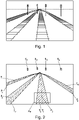
- FIG. 1 One example of such an image I t is shown in Fig. 1 .
- the image contains rail track-regions T 1 , ..., T 4 each of which depicts one rail track.
- the image I t contains signal-regions S 1 , ..., S 4 , eachof which shows one signal.
- the image of the image sensor is transmitted to a processing unit, which is used to further execute the following steps (b) to (g).
- a classification method is used in order to automatically detect the rail track-regions T 1 , ..., T 4 and the signal-regions S 1 , ..., S 4 .
- Railtracks can be detected either using classical approaches, e.g. shown in Rui Fan and Naim Dahnoun "Real-Time Stereo Vision-Based Lane Detection System", 2018 or Han Ma et el. "Multiple Lane Detection Algorithm Based on Optimised Dense Disparity Map Estimation", 2018 .
- Classical approaches usually first extract the edges or lines from the rail track-regions and then apply curve fitting to refine the railtracks.
- machine learning algorithms which e.g. train an end-to-end neural network to segment the railtracks from the background; such methods are known from the state of the art, in particular from Davy Neven, Bert De Brabandere, Stamatios Georgoulis, Marc Proesmans and Luc Van Gool "Towards End-to-End Lane Detection: an Instance Segmentation Approach", 2018 or Min Bai et el. "Deep Multi-Sensor Lane Detection", 2018 .
- the position of the actual rail track within the image I t is determined. Therefore, the regions of the current rail track, i.e. the rail track T C that is actually used by the train, is identified.
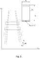
- the rail track T C used by the train and the respective region of the rail track T C within the image I t can be found by searching one of the rail track regions T t containing rail tracks already identified in step (b) that goes through or overlaps with a predefined image area A p as shown in Fig. 2 .
- This image area A p usually depends on the orientation of the image sensor within the train. If an image sensor is heading straight in the direction of movement, the predefined image area A p is in the center of the lower part of the image I t .
- the image area A p can be easily defined after mounting the image sensor in or on the train by searching for a region of the image, which is close to the train and which shows a part of the rail track, independently of the curvature of the rail track.
- step (b) it is also possible to search for the regions T t having the maximum area or containing maximum pixels among the rail tracks identified in step (b).
- the rail track currently used is close to the image sensor, it typically covers a bigger region within the image I t than the other rail track regions.
- the rail track identified in step (c) is represented by a center path P c .
- the positions of the ground points G 1 , ..., G 4 of the signals S T are estimated with respect to the image I t .
- the ground point G 1 , ..., G 4 is the point within the image that shows the base point of the pole. More generally, the ground point is the point within the image I t that depicts a surface point, which is directly underneath the respective signal S, even if the signal is not mounted on a pole, but e.g. mounted on overhead infrastructure.
- the following prerequisites are typically needed. Firstly, the size, i.e. height and width, of the panels of the signals are known. If there are different types of signals available, said type has to be firstly estimated by the shape and/or content of the image region of the signal.
- a typical kind of signal could have a rectangular panel of 1.4-meters height and 0.7-meters width. Moreover, the signal could typically be mounted in a height of 4.85-meters to 6.95-meters (see Fig. 3 ).
- the image sensor is mounted on the train in a manner that its y-axis is - at least approximately - aligned vertically, and its x-axis is - at least approximately - aligned horizontally.
- the height h t and width w t of the image region of the signal can be obtained by different methods, such as detection of an axis-parallel bounding box, etc.
- ground point is at a position between 194 px and 278 px under the lower edge of the signal's image region S t .
- an average pole height for example of 6-meters can be used, which would lead to a y-distance d t of 240 px.
- the lower edge position y l,t is defined as the highest or least y-position, depending on the orientation of the y-axis of the image sensor.
- the horizontal center x m,t of the signal region is defined as the x-coordinate of the centroid of the signal region.
- the ground point G t can be determined by calculating an offset from an image position within the region of the signal S t , wherein the offset is defined by the size, in particular by a length on the region of the signal S t .
- the ground point G t can be determined by calculating width and height of a rectangular bounding box that is parallel to the image axes.
- the position of a ground point G t underneath the signal was estimated from the image by projection of the signal within the image I t to the ground plane.
- a perspective transformation R is determined, by which it is possible to transform the sensor image I t into the projection plane; as this projection plane is - in this very example - parallel to the ground plane, the transformation returns a bird's eye view image I B .
- the transformation R is a perspective transformation, that is based on visual properties of the image and/or mounting properties of the image sensor.
- One particular method to determine the transformation R is to find a trapezoidal region R T within the region Tc of the actual rail track. Based on the mounting properties of the image sensor and the assumption of a sufficiently flat and smooth track bed it is clear, that this trapezoidal region R T typically covers a rectangular region R R within a bird's eye view image I B .
- the perspective transformation is defined in such way, that it transforms at least a trapezoidal part of the region T c of the actual rail track to a rectangular region within the bird's eye view image I B .
- the perspective transformation R is in a further step (f) applied to the selected rail track, in particular to a central path P 1 , ..., P 4 within the rail track, and to the ground points that were determined in step (d). From these data it is possible to determine real-world distances, or it is at least possible to compare distances of ground points to the actual rail track.
- a ground point G t and its respective signal S t should be associated with the actual rail track only if the distance from the ground point G t to the region, in particular the path P c , of the selected rail track S t under said perspective transformation R is below a predefined threshold distance.
- a regulation sets out more complicated rules relating to the association of signals with rail tracks. These regulations can rely on the determined distances and/or relative placement, e.g. right or left from the rail track, only. However, it is also possible that there are more complex rules relating to the association of rail tracks and signals that are based on a sequence of detections or the position of the train and the signal in the railway network. These rules may rely on distances, relative placement and sequences of signals on the rail track.
- An advanced second embodiment of the invention uses the method as described above in order to determine images of signals that are associated with the actual rail track.
- this embodiment also relies on a geolocation-map, containing the location of the rail tracks t A , ..., t G as well as the position S A , ..., S L of the signals ( Fig. 5 ) .
- a geolocation-unit is used, the geolocation-unit being connected or integrated to the processing unit.
- the geolocation-unit provides the actual geolocation of the train which is further processed by the processing unit as follows.
- GNSS Global Navigation Satellite System
- SLAM Simultaneous Localization And Mapping
- the method for detecting image regions of signals, which are associated with the actual rail track as shown in the first embodiment of the invention only needs to be carried out, if such a signal is expected based on the geolocation method as explained above. If, such as for the position e 3 , there is no on-coming signal within the associated region E 3 , the visual search for signals is turned off in order to reduce the likelihood for false positive matches.
- the associated region E 1 contains many ground points S F , S G , S I , S J . However, none of these ground points are associated with the actual rail track t C so that there is no on-coming signal; the method for detecting image regions of signals is turned off.
- the method for detecting image regions of signals is carried out in order to find a visual representation of said signal in the image I t .
- the information relating to the map positions of signals can be used in order to further avoid false positive detections of signals with respect to both further described embodiments of the invention.
- a matching algorithm is used in order to match the rail tracks t A , ..., t G of the map to the rail tracks as contained in bird's eye view image I B . If a selected ground point G t matches the geolocation of a signal of the predefined map, which is associated with the actual path as determined by the geolocation, the overall reliability of the result will be increased.
- the image region containing an image of the identified signal it is possible to display the image region containing an image of the identified signal to the train driver.
- the procedure as described above is repeated regularly so as to provide a video in order to inform the train driver about relevant on-coming signals.
- any other event can be triggered by the information automatically retrieved from the image such as simple audible, visual, or haptic warning.
Landscapes
- Engineering & Computer Science (AREA)
- Mechanical Engineering (AREA)
- Train Traffic Observation, Control, And Security (AREA)
Claims (4)
- Procédé de détection d'un signal de chemin de fer associé à la voie ferrée utilisée par un train, comprenant les étapes consistant àa) prendre au moins une image bidimensionnelle (It) à partir du train avec un capteur d'image situé dans ou sur le train générant une image des voies ferrées venant en sens inverse et de signaux,
dans lequel le capteur d'image est monté dans ou sur le train de manière à ce que son axe y soit aligné sensiblement verticalement, et son axe x soit aligné sensiblement horizontalement,b) utiliser un procédé de classification pour identifier des régions d'image (Tt) correspondant à des voies ferrées et des régions d'image (St) correspondant à des signaux dans l'image (It),c) parmi lesdites régions d'image identifiées (Tt) correspondant à des voies ferrées, sélectionner la région d'image (Tc) qui correspond à la voie ferrée qui est utilisée par le train, en particulier en identifiant la voie ferrée- parcourir une région prédéfinie de l'image, et/ou- présenter la surface ou la taille de pixel maximum parmi les voies ferrées identifiées à l'étape b),d) pour chacune des régions d'image (St) correspondant à un signal (S) :- estimer des points projetés des signaux et la trajectoire projetée de la voie ferrée sélectionnée (Tc) dans un plan de projection commun, en particulier un plan de masse,
dans lequel le point projeté du signal est estimé comme la position d'un point de masse (Gt) du signal respectif à l'intérieur de l'image (It),- dans lequel le point de masse (Gt) est le point à l'intérieur de l'image (It) qui représente un point de surface, qui se trouve directement sous le signal respectif (S), et- dans lequel la hauteur et la largeur des panneaux du signal respectif (S) sont connues ou estimées par la forme et/ou le contenu de la région d'image (St) du signal (S), dans lequel la détermination du point de masse (Gt) du signal (S) comprend les étapes suivantes consistant à :- déterminer une hauteur de pixel ht et une largeur de pixel wt de la région d'image (St) du signal de la manière suivante :- compter un nombre de pixels A correspondant à la région d'image (St) du signal- déterminer la largeur de pixel wt de la région d'image (St) du signal en utilisant la relation : - déterminer la hauteur de pixel ht de ladite région d'image (St) du signal en utilisant un rapport connu r entre la hauteur et la largeur du panneau du signal (S),- calculer une distance y dt entre un bord inférieur de la région d'image (St) du signal et le point de masse respectif (Gt) à partir de la hauteur de pixel ht qui correspond à la hauteur connue du signal (S) en utilisant la relation :
 - définir les coordonnées du point de masse (Gt) sur la base du bord inférieur de la région d'image (St) du signal ainsi que d'un centre horizontal de la région d'image (St) du signal sous la forme :
 - dans lequel la position de bord inférieur yl,t de la région d'image (St) du signal est définie comme la position y la plus élevée ou la plus faible, en fonction de l'orientation de l'axe y du capteur d'image, et- dans lequel le centre horizontal xm,t de la région d'image (St) du signal est défini comme la coordonnée x du centroïde de la région d'image (St) du signal,e) estimer une transformation de perspective (R) pour transformer l'image (It) dans le plan de projection commun, de préférence dans une image vue du ciel (IB) sur la base de propriétés visuelles de l'image et/ou de propriétés de montage du capteur d'image,f) appliquer la transformation de perspective- à la région d'image sélectionnée (Tc) ou à des parties de celle-ci, en particulier un trajet central à l'intérieur de la voie ferrée, et- aux points projetés, etg) déterminer un ou plusieurs points projetés (Gt) qui présentent une distance minimum et/ou une distance inférieure à une distance de seuil prédéfinie et/ou un placement relatif par rapport à la région d'image sélectionnée (Tc) sous ladite transformation de perspective (R) et identifier les signaux et/ ou les régions d'image (St) correspondant à des signaux associés à ces points projetés dans l'image (It)
 - Procédé selon la revendication 1, caractérisé par les étapes suivantes consistant à :- fournir une carte du réseau de chemin de fer incluant les positions des voies ferrées et des signaux, dans lequel chaque signal étant associé à une voie ferrée,- localiser la position du train sur la carte de chemin de fer et la voie ferrée qu'il utilise,- utiliser la carte pour déterminer la position du signal d'approche associé à la voie ferrée qu'il utilise,- uniquement si le signal d'approche se trouve dans une région prédéterminée devant le train, prendre une image et exécuter le procédé de la revendication 1.
- Système de détection d'un signal ferroviaire, qui est associé à la voie ferrée utilisée par un train, comprenant- un capteur d'image monté ou pouvant être monté dans ou sur le train qui est agencé pour prendre au moins une image bidimensionnelle (It) des voies ferrées et des signaux en approche, dans lequel le capteur d'image est monté dans ou sur le train d'une manière telle que son axe y est aligné sensiblement verticalement, et son axe x est aligné sensiblement horizontalement, et- une unité de traitement qui est connectée au capteur d'image qui est programmée pour exécuter les étapes suivantes consistant à :b) utiliser un procédé de classification pour identifier des régions d'image (Tt) correspondant à des voies ferrées et des régions d'image (St) correspondant à des signaux dans l'image (It),c) parmi lesdites régions d'image identifiées (Tt) correspondant à des voies ferrées, sélectionner la région d'image (Tc) qui correspond à la voie ferrée qui est utilisée par le train, en particulier en identifiant la voie ferrée- parcourir une région prédéfinie de l'image, et/ou- présenter la surface ou la taille de pixel maximum parmi les voies ferrées identifiées à l'étape b),d) pour chacune des régions d'image (St) correspondant à un signal (S) :- estimer des points projetés des signaux et la trajectoire projetée de la voie ferrée sélectionnée (Tc) dans un plan de projection commun, en particulier un plan de masse, dans lequel le point projeté du signal est estimé comme la position d'un point de masse (Gt) du signal respectif dans l'image (It),- dans lequel le point de masse (Gt) est le point dans l'image (It) qui représente un point de surface, qui est directement sous le signal respectif (S), et- dans lequel la hauteur et la largeur des panneaux du signal respectif (S) sont connues ou estimées par la forme et/ou le contenu de la région d'image (St) du signal (S),dans lequel la détermination du point de masse (Gt) du signal (S) comprend les étapes suivantes consistant à :- déterminer une hauteur de pixel ht et une largeur de pixel wt de la région d'image (St) du signal de la manière suivante :- compter un nombre de pixels A correspondant à la région d'image (St) du signal- déterminer la largeur de pixel wt de la région d'image (St) du signal en utilisant la relation :
 - déterminer la hauteur de pixel ht de ladite région d'image (St) du signal en utilisant un rapport connu r entre la hauteur et la largeur du panneau du signal (S),- calculer une distance y dt entre un bord inférieur de la région d'image (St) du signal et le point de masse respectif (Gt) à partir de la hauteur de pixel ht qui correspond à la hauteur connue du signal (S) en utilisant la relation :
 - définir les coordonnées du point de masse (Gt) sur la base du bord inférieur de la région d'image (St) du signal ainsi que d'un centre horizontal de la région d'image (St) du signal sous la forme :
 - dans lequel la position de bord inférieur yl, t de la région d'image (St) du signal est définie comme la position y la plus élevée ou la plus faible, en fonction de l'orientation de l'axe y du capteur d'image, et- dans lequel le centre horizontal xm,t de la région d'image (St) du signal est défini comme la coordonnée x du centroïde de la région d'image (St) du signal,e) estimer une transformation de perspective (R) pour transformer l'image (It) dans le plan de projection commun, de préférence dans une image vue du ciel (IB), sur la base de propriétés visuelles de l'image et/ou de propriétés de montage du capteur d'image,f) appliquer la transformation de perspective- à la région d'image sélectionnée (Tc) ou à des parties de celle-ci, en particulier un trajet central à l'intérieur de la voie ferrée, et- aux points projetés, etg) déterminer un ou plusieurs points projetés (Gt) qui présentent une distance minimum et/ou une distance inférieure à une distance de seuil prédéfinie et/ou un placement relatif par rapport à la région d'image sélectionnée (Tc) sous ladite transformation de perspective (R) et identifier les signaux et/ou les régions d'image (St) correspondant à des signaux associés à ces points projetés dans l'image (It).
 - Système selon la revendication 3, caractérisé en outre par une unité de géolocalisation connectée à l'unité de traitement, dans lequel- l'unité de traitement comprend en outre une mémoire pour une carte du réseau de chemin de fer incluant les positions des voies ferrées et des signaux, dans lequel chaque signal est associé à une voie ferrée, et- l'unité de traitement est en outre programmée pour exécuter les étapes suivantes consistant à :- trouver la position du train fournie par l'unité de géolocalisation au sein de la carte de chemin de fer et la voie ferrée qu'il utilise,- utiliser la carte pour déterminer la position du signal d'approche associé à la voie ferrée qu'il utilise, et- uniquement si le signal d'approche se trouve dans une région prédéterminée devant le train, prendre une image et exécuter les étapes b) à g) de la revendication 3.
Priority Applications (4)
| Application Number | Priority Date | Filing Date | Title |
|---|---|---|---|
| ES19179792T ES2930674T3 (es) | 2019-06-12 | 2019-06-12 | Método y sistema para detectar una señal ferroviaria |
| EP19179792.7A EP3750776B1 (fr) | 2019-06-12 | 2019-06-12 | Procédé et système de détection d'un signal de chemin de fer |
| PCT/EP2020/065968 WO2020249558A1 (fr) | 2019-06-12 | 2020-06-09 | Procédé pour détecter un signal de chemin de fer |
| IL288651A IL288651B1 (en) | 2019-06-12 | 2020-06-09 | Method and system for detecting a track signal |
Applications Claiming Priority (1)
| Application Number | Priority Date | Filing Date | Title |
|---|---|---|---|
| EP19179792.7A EP3750776B1 (fr) | 2019-06-12 | 2019-06-12 | Procédé et système de détection d'un signal de chemin de fer |
Publications (2)
| Publication Number | Publication Date |
|---|---|
| EP3750776A1 EP3750776A1 (fr) | 2020-12-16 |
| EP3750776B1 true EP3750776B1 (fr) | 2022-08-24 |
Family
ID=66857677
Family Applications (1)
| Application Number | Title | Priority Date | Filing Date |
|---|---|---|---|
| EP19179792.7A Active EP3750776B1 (fr) | 2019-06-12 | 2019-06-12 | Procédé et système de détection d'un signal de chemin de fer |
Country Status (4)
| Country | Link |
|---|---|
| EP (1) | EP3750776B1 (fr) |
| ES (1) | ES2930674T3 (fr) |
| IL (1) | IL288651B1 (fr) |
| WO (1) | WO2020249558A1 (fr) |
Families Citing this family (2)
| Publication number | Priority date | Publication date | Assignee | Title |
|---|---|---|---|---|
| FR3142983A1 (fr) * | 2022-12-08 | 2024-06-14 | Alstom Holdings | Procédé pour déterminer la position d’un véhicule ferroviaire |
| DE102024203289A1 (de) * | 2024-04-10 | 2025-10-16 | Siemens Mobility GmbH | Verfahren und Einrichtungen zum Betreiben eines Schienenfahrzeugs |
Family Cites Families (2)
| Publication number | Priority date | Publication date | Assignee | Title |
|---|---|---|---|---|
| US9796400B2 (en) * | 2013-11-27 | 2017-10-24 | Solfice Research, Inc. | Real time machine vision and point-cloud analysis for remote sensing and vehicle control |
| EP3048559A1 (fr) * | 2015-01-21 | 2016-07-27 | RindInvest AB | Procédé et système de détection d'une voie ferrée |
-
2019
- 2019-06-12 ES ES19179792T patent/ES2930674T3/es active Active
- 2019-06-12 EP EP19179792.7A patent/EP3750776B1/fr active Active
-
2020
- 2020-06-09 IL IL288651A patent/IL288651B1/en unknown
- 2020-06-09 WO PCT/EP2020/065968 patent/WO2020249558A1/fr not_active Ceased
Also Published As
| Publication number | Publication date |
|---|---|
| WO2020249558A1 (fr) | 2020-12-17 |
| IL288651B1 (en) | 2026-02-01 |
| EP3750776A1 (fr) | 2020-12-16 |
| IL288651A (en) | 2022-02-01 |
| ES2930674T3 (es) | 2022-12-20 |
Similar Documents
| Publication | Publication Date | Title |
|---|---|---|
| EP2431917B1 (fr) | Détection de barrière et de glissière de sécurité utilisant une caméra unique | |
| US11024051B2 (en) | Object detection device | |
| US11280630B2 (en) | Updating map data | |
| US6819779B1 (en) | Lane detection system and apparatus | |
| JP5297078B2 (ja) | 車両の死角における移動物体を検知するための方法、および死角検知装置 | |
| Miyasaka et al. | Ego-motion estimation and moving object tracking using multi-layer lidar | |
| US11514683B2 (en) | Outside recognition apparatus for vehicle | |
| US20150073705A1 (en) | Vehicle environment recognition apparatus | |
| EP3048559A1 (fr) | Procédé et système de détection d'une voie ferrée | |
| JP7675339B2 (ja) | 物体追跡装置 | |
| CN109791598A (zh) | 用于识别地面标记的图像处理方法以及地面标记检测系统 | |
| JP2008123462A (ja) | 物体検知装置 | |
| JP2005136946A (ja) | 路上走行車両用のカメラ式位置認識装置および方法 | |
| JP2016148962A (ja) | 物体検知装置 | |
| JP2014199546A (ja) | 運転支援装置及び運転支援方法 | |
| EP3223241A1 (fr) | Dispositif de reconnaissance d'itinéraire de déplacement et système d'aide au déplacement faisant intervenir ce dernier | |
| JP2021120255A (ja) | 距離推定装置及び距離推定用コンピュータプログラム | |
| EP3750776B1 (fr) | Procédé et système de détection d'un signal de chemin de fer | |
| Baehring et al. | Detection of close cut-in and overtaking vehicles for driver assistance based on planar parallax | |
| JP2014026519A (ja) | 車載レーンマーカ認識装置 | |
| US12498228B1 (en) | Detecting and resolving disparities between map data and environments perceived by sensor systems | |
| JP2011103058A (ja) | 誤認識防止装置 | |
| JP2002008019A (ja) | 軌道認識装置及び軌道認識装置を用いた鉄道車両 | |
| KR20060134719A (ko) | 차량의 주차 구획 인식방법 | |
| EP4579581A1 (fr) | Dispositif de reconnaissance du monde extérieur et procédé de reconnaissance du monde extérieur |
Legal Events
| Date | Code | Title | Description |
|---|---|---|---|
| PUAI | Public reference made under article 153(3) epc to a published international application that has entered the european phase |
Free format text: ORIGINAL CODE: 0009012 |
|
| STAA | Information on the status of an ep patent application or granted ep patent |
Free format text: STATUS: THE APPLICATION HAS BEEN PUBLISHED |
|
| AK | Designated contracting states |
Kind code of ref document: A1 Designated state(s): AL AT BE BG CH CY CZ DE DK EE ES FI FR GB GR HR HU IE IS IT LI LT LU LV MC MK MT NL NO PL PT RO RS SE SI SK SM TR |
|
| AX | Request for extension of the european patent |
Extension state: BA ME |
|
| STAA | Information on the status of an ep patent application or granted ep patent |
Free format text: STATUS: REQUEST FOR EXAMINATION WAS MADE |
|
| 17P | Request for examination filed |
Effective date: 20210323 |
|
| RBV | Designated contracting states (corrected) |
Designated state(s): AL AT BE BG CH CY CZ DE DK EE ES FI FR GB GR HR HU IE IS IT LI LT LU LV MC MK MT NL NO PL PT RO RS SE SI SK SM TR |
|
| GRAP | Despatch of communication of intention to grant a patent |
Free format text: ORIGINAL CODE: EPIDOSNIGR1 |
|
| STAA | Information on the status of an ep patent application or granted ep patent |
Free format text: STATUS: GRANT OF PATENT IS INTENDED |
|
| RIC1 | Information provided on ipc code assigned before grant |
Ipc: G06T 3/00 20060101ALN20220128BHEP Ipc: B61L 3/00 20060101ALN20220128BHEP Ipc: B61L 23/04 20060101AFI20220128BHEP |
|
| INTG | Intention to grant announced |
Effective date: 20220309 |
|
| GRAS | Grant fee paid |
Free format text: ORIGINAL CODE: EPIDOSNIGR3 |
|
| GRAA | (expected) grant |
Free format text: ORIGINAL CODE: 0009210 |
|
| STAA | Information on the status of an ep patent application or granted ep patent |
Free format text: STATUS: THE PATENT HAS BEEN GRANTED |
|
| AK | Designated contracting states |
Kind code of ref document: B1 Designated state(s): AL AT BE BG CH CY CZ DE DK EE ES FI FR GB GR HR HU IE IS IT LI LT LU LV MC MK MT NL NO PL PT RO RS SE SI SK SM TR |
|
| REG | Reference to a national code |
Ref country code: CH Ref legal event code: EP |
|
| REG | Reference to a national code |
Ref country code: IE Ref legal event code: FG4D |
|
| REG | Reference to a national code |
Ref country code: AT Ref legal event code: REF Ref document number: 1513471 Country of ref document: AT Kind code of ref document: T Effective date: 20220915 Ref country code: DE Ref legal event code: R096 Ref document number: 602019018555 Country of ref document: DE |
|
| REG | Reference to a national code |
Ref country code: LT Ref legal event code: MG9D |
|
| REG | Reference to a national code |
Ref country code: ES Ref legal event code: FG2A Ref document number: 2930674 Country of ref document: ES Kind code of ref document: T3 Effective date: 20221220 |
|
| REG | Reference to a national code |
Ref country code: NL Ref legal event code: MP Effective date: 20220824 |
|
| PG25 | Lapsed in a contracting state [announced via postgrant information from national office to epo] |
Ref country code: SE Free format text: LAPSE BECAUSE OF FAILURE TO SUBMIT A TRANSLATION OF THE DESCRIPTION OR TO PAY THE FEE WITHIN THE PRESCRIBED TIME-LIMIT Effective date: 20220824 Ref country code: RS Free format text: LAPSE BECAUSE OF FAILURE TO SUBMIT A TRANSLATION OF THE DESCRIPTION OR TO PAY THE FEE WITHIN THE PRESCRIBED TIME-LIMIT Effective date: 20220824 Ref country code: PT Free format text: LAPSE BECAUSE OF FAILURE TO SUBMIT A TRANSLATION OF THE DESCRIPTION OR TO PAY THE FEE WITHIN THE PRESCRIBED TIME-LIMIT Effective date: 20221226 Ref country code: NO Free format text: LAPSE BECAUSE OF FAILURE TO SUBMIT A TRANSLATION OF THE DESCRIPTION OR TO PAY THE FEE WITHIN THE PRESCRIBED TIME-LIMIT Effective date: 20221124 Ref country code: NL Free format text: LAPSE BECAUSE OF FAILURE TO SUBMIT A TRANSLATION OF THE DESCRIPTION OR TO PAY THE FEE WITHIN THE PRESCRIBED TIME-LIMIT Effective date: 20220824 Ref country code: LV Free format text: LAPSE BECAUSE OF FAILURE TO SUBMIT A TRANSLATION OF THE DESCRIPTION OR TO PAY THE FEE WITHIN THE PRESCRIBED TIME-LIMIT Effective date: 20220824 Ref country code: LT Free format text: LAPSE BECAUSE OF FAILURE TO SUBMIT A TRANSLATION OF THE DESCRIPTION OR TO PAY THE FEE WITHIN THE PRESCRIBED TIME-LIMIT Effective date: 20220824 Ref country code: FI Free format text: LAPSE BECAUSE OF FAILURE TO SUBMIT A TRANSLATION OF THE DESCRIPTION OR TO PAY THE FEE WITHIN THE PRESCRIBED TIME-LIMIT Effective date: 20220824 |
|
| PG25 | Lapsed in a contracting state [announced via postgrant information from national office to epo] |
Ref country code: PL Free format text: LAPSE BECAUSE OF FAILURE TO SUBMIT A TRANSLATION OF THE DESCRIPTION OR TO PAY THE FEE WITHIN THE PRESCRIBED TIME-LIMIT Effective date: 20220824 Ref country code: IS Free format text: LAPSE BECAUSE OF FAILURE TO SUBMIT A TRANSLATION OF THE DESCRIPTION OR TO PAY THE FEE WITHIN THE PRESCRIBED TIME-LIMIT Effective date: 20221224 Ref country code: HR Free format text: LAPSE BECAUSE OF FAILURE TO SUBMIT A TRANSLATION OF THE DESCRIPTION OR TO PAY THE FEE WITHIN THE PRESCRIBED TIME-LIMIT Effective date: 20220824 Ref country code: GR Free format text: LAPSE BECAUSE OF FAILURE TO SUBMIT A TRANSLATION OF THE DESCRIPTION OR TO PAY THE FEE WITHIN THE PRESCRIBED TIME-LIMIT Effective date: 20221125 |
|
| PG25 | Lapsed in a contracting state [announced via postgrant information from national office to epo] |
Ref country code: SM Free format text: LAPSE BECAUSE OF FAILURE TO SUBMIT A TRANSLATION OF THE DESCRIPTION OR TO PAY THE FEE WITHIN THE PRESCRIBED TIME-LIMIT Effective date: 20220824 Ref country code: RO Free format text: LAPSE BECAUSE OF FAILURE TO SUBMIT A TRANSLATION OF THE DESCRIPTION OR TO PAY THE FEE WITHIN THE PRESCRIBED TIME-LIMIT Effective date: 20220824 Ref country code: DK Free format text: LAPSE BECAUSE OF FAILURE TO SUBMIT A TRANSLATION OF THE DESCRIPTION OR TO PAY THE FEE WITHIN THE PRESCRIBED TIME-LIMIT Effective date: 20220824 |
|
| REG | Reference to a national code |
Ref country code: DE Ref legal event code: R097 Ref document number: 602019018555 Country of ref document: DE |
|
| PG25 | Lapsed in a contracting state [announced via postgrant information from national office to epo] |
Ref country code: SK Free format text: LAPSE BECAUSE OF FAILURE TO SUBMIT A TRANSLATION OF THE DESCRIPTION OR TO PAY THE FEE WITHIN THE PRESCRIBED TIME-LIMIT Effective date: 20220824 Ref country code: EE Free format text: LAPSE BECAUSE OF FAILURE TO SUBMIT A TRANSLATION OF THE DESCRIPTION OR TO PAY THE FEE WITHIN THE PRESCRIBED TIME-LIMIT Effective date: 20220824 |
|
| PG25 | Lapsed in a contracting state [announced via postgrant information from national office to epo] |
Ref country code: AL Free format text: LAPSE BECAUSE OF FAILURE TO SUBMIT A TRANSLATION OF THE DESCRIPTION OR TO PAY THE FEE WITHIN THE PRESCRIBED TIME-LIMIT Effective date: 20220824 |
|
| PLBE | No opposition filed within time limit |
Free format text: ORIGINAL CODE: 0009261 |
|
| STAA | Information on the status of an ep patent application or granted ep patent |
Free format text: STATUS: NO OPPOSITION FILED WITHIN TIME LIMIT |
|
| P01 | Opt-out of the competence of the unified patent court (upc) registered |
Effective date: 20230621 |
|
| 26N | No opposition filed |
Effective date: 20230525 |
|
| PG25 | Lapsed in a contracting state [announced via postgrant information from national office to epo] |
Ref country code: SI Free format text: LAPSE BECAUSE OF FAILURE TO SUBMIT A TRANSLATION OF THE DESCRIPTION OR TO PAY THE FEE WITHIN THE PRESCRIBED TIME-LIMIT Effective date: 20220824 |
|
| PG25 | Lapsed in a contracting state [announced via postgrant information from national office to epo] |
Ref country code: MC Free format text: LAPSE BECAUSE OF FAILURE TO SUBMIT A TRANSLATION OF THE DESCRIPTION OR TO PAY THE FEE WITHIN THE PRESCRIBED TIME-LIMIT Effective date: 20220824 |
|
| PG25 | Lapsed in a contracting state [announced via postgrant information from national office to epo] |
Ref country code: MC Free format text: LAPSE BECAUSE OF FAILURE TO SUBMIT A TRANSLATION OF THE DESCRIPTION OR TO PAY THE FEE WITHIN THE PRESCRIBED TIME-LIMIT Effective date: 20220824 |
|
| REG | Reference to a national code |
Ref country code: BE Ref legal event code: MM Effective date: 20230630 |
|
| PG25 | Lapsed in a contracting state [announced via postgrant information from national office to epo] |
Ref country code: LU Free format text: LAPSE BECAUSE OF NON-PAYMENT OF DUE FEES Effective date: 20230612 |
|
| PG25 | Lapsed in a contracting state [announced via postgrant information from national office to epo] |
Ref country code: LU Free format text: LAPSE BECAUSE OF NON-PAYMENT OF DUE FEES Effective date: 20230612 |
|
| PG25 | Lapsed in a contracting state [announced via postgrant information from national office to epo] |
Ref country code: IT Free format text: LAPSE BECAUSE OF FAILURE TO SUBMIT A TRANSLATION OF THE DESCRIPTION OR TO PAY THE FEE WITHIN THE PRESCRIBED TIME-LIMIT Effective date: 20220824 Ref country code: BE Free format text: LAPSE BECAUSE OF NON-PAYMENT OF DUE FEES Effective date: 20230630 |
|
| PG25 | Lapsed in a contracting state [announced via postgrant information from national office to epo] |
Ref country code: BG Free format text: LAPSE BECAUSE OF FAILURE TO SUBMIT A TRANSLATION OF THE DESCRIPTION OR TO PAY THE FEE WITHIN THE PRESCRIBED TIME-LIMIT Effective date: 20220824 |
|
| PG25 | Lapsed in a contracting state [announced via postgrant information from national office to epo] |
Ref country code: BG Free format text: LAPSE BECAUSE OF FAILURE TO SUBMIT A TRANSLATION OF THE DESCRIPTION OR TO PAY THE FEE WITHIN THE PRESCRIBED TIME-LIMIT Effective date: 20220824 |
|
| PGFP | Annual fee paid to national office [announced via postgrant information from national office to epo] |
Ref country code: DE Payment date: 20250618 Year of fee payment: 7 |
|
| PGFP | Annual fee paid to national office [announced via postgrant information from national office to epo] |
Ref country code: GB Payment date: 20250618 Year of fee payment: 7 |
|
| PGFP | Annual fee paid to national office [announced via postgrant information from national office to epo] |
Ref country code: FR Payment date: 20250626 Year of fee payment: 7 |
|
| PGFP | Annual fee paid to national office [announced via postgrant information from national office to epo] |
Ref country code: AT Payment date: 20250627 Year of fee payment: 7 |
|
| PG25 | Lapsed in a contracting state [announced via postgrant information from national office to epo] |
Ref country code: CY Free format text: LAPSE BECAUSE OF FAILURE TO SUBMIT A TRANSLATION OF THE DESCRIPTION OR TO PAY THE FEE WITHIN THE PRESCRIBED TIME-LIMIT; INVALID AB INITIO Effective date: 20190612 |
|
| PGFP | Annual fee paid to national office [announced via postgrant information from national office to epo] |
Ref country code: CZ Payment date: 20250603 Year of fee payment: 7 |
|
| PGFP | Annual fee paid to national office [announced via postgrant information from national office to epo] |
Ref country code: IE Payment date: 20250618 Year of fee payment: 7 |
|
| PG25 | Lapsed in a contracting state [announced via postgrant information from national office to epo] |
Ref country code: HU Free format text: LAPSE BECAUSE OF FAILURE TO SUBMIT A TRANSLATION OF THE DESCRIPTION OR TO PAY THE FEE WITHIN THE PRESCRIBED TIME-LIMIT; INVALID AB INITIO Effective date: 20190612 |
|
| PGFP | Annual fee paid to national office [announced via postgrant information from national office to epo] |
Ref country code: ES Payment date: 20250731 Year of fee payment: 7 |
|
| PGFP | Annual fee paid to national office [announced via postgrant information from national office to epo] |
Ref country code: CH Payment date: 20250701 Year of fee payment: 7 |
|
| PG25 | Lapsed in a contracting state [announced via postgrant information from national office to epo] |
Ref country code: TR Free format text: LAPSE BECAUSE OF FAILURE TO SUBMIT A TRANSLATION OF THE DESCRIPTION OR TO PAY THE FEE WITHIN THE PRESCRIBED TIME-LIMIT Effective date: 20220824 |