EP3750971B1 - Dispositif électroluminescent organique - Google Patents
Dispositif électroluminescent organique Download PDFInfo
- Publication number
- EP3750971B1 EP3750971B1 EP20179629.9A EP20179629A EP3750971B1 EP 3750971 B1 EP3750971 B1 EP 3750971B1 EP 20179629 A EP20179629 A EP 20179629A EP 3750971 B1 EP3750971 B1 EP 3750971B1
- Authority
- EP
- European Patent Office
- Prior art keywords
- substituted
- unsubstituted
- formula
- organic electroluminescent
- compound
- Prior art date
- Legal status (The legal status is an assumption and is not a legal conclusion. Google has not performed a legal analysis and makes no representation as to the accuracy of the status listed.)
- Active
Links
Classifications
-
- C—CHEMISTRY; METALLURGY
- C09—DYES; PAINTS; POLISHES; NATURAL RESINS; ADHESIVES; COMPOSITIONS NOT OTHERWISE PROVIDED FOR; APPLICATIONS OF MATERIALS NOT OTHERWISE PROVIDED FOR
- C09K—MATERIALS FOR MISCELLANEOUS APPLICATIONS, NOT PROVIDED FOR ELSEWHERE
- C09K11/00—Luminescent materials, e.g. electroluminescent or chemiluminescent
- C09K11/06—Luminescent materials, e.g. electroluminescent or chemiluminescent containing organic luminescent materials
-
- C—CHEMISTRY; METALLURGY
- C07—ORGANIC CHEMISTRY
- C07F—ACYCLIC, CARBOCYCLIC OR HETEROCYCLIC COMPOUNDS CONTAINING ELEMENTS OTHER THAN CARBON, HYDROGEN, HALOGEN, OXYGEN, NITROGEN, SULFUR, SELENIUM OR TELLURIUM
- C07F5/00—Compounds containing elements of Groups 3 or 13 of the Periodic Table
- C07F5/02—Boron compounds
- C07F5/027—Organoboranes and organoborohydrides
-
- H—ELECTRICITY
- H10—SEMICONDUCTOR DEVICES; ELECTRIC SOLID-STATE DEVICES NOT OTHERWISE PROVIDED FOR
- H10K—ORGANIC ELECTRIC SOLID-STATE DEVICES
- H10K50/00—Organic light-emitting devices
- H10K50/10—OLEDs or polymer light-emitting diodes [PLED]
- H10K50/11—OLEDs or polymer light-emitting diodes [PLED] characterised by the electroluminescent [EL] layers
- H10K50/12—OLEDs or polymer light-emitting diodes [PLED] characterised by the electroluminescent [EL] layers comprising dopants
-
- H—ELECTRICITY
- H10—SEMICONDUCTOR DEVICES; ELECTRIC SOLID-STATE DEVICES NOT OTHERWISE PROVIDED FOR
- H10K—ORGANIC ELECTRIC SOLID-STATE DEVICES
- H10K85/00—Organic materials used in the body or electrodes of devices covered by this subclass
- H10K85/60—Organic compounds having low molecular weight
- H10K85/615—Polycyclic condensed aromatic hydrocarbons, e.g. anthracene
-
- H—ELECTRICITY
- H10—SEMICONDUCTOR DEVICES; ELECTRIC SOLID-STATE DEVICES NOT OTHERWISE PROVIDED FOR
- H10K—ORGANIC ELECTRIC SOLID-STATE DEVICES
- H10K85/00—Organic materials used in the body or electrodes of devices covered by this subclass
- H10K85/60—Organic compounds having low molecular weight
- H10K85/615—Polycyclic condensed aromatic hydrocarbons, e.g. anthracene
- H10K85/622—Polycyclic condensed aromatic hydrocarbons, e.g. anthracene containing four rings, e.g. pyrene
-
- H—ELECTRICITY
- H10—SEMICONDUCTOR DEVICES; ELECTRIC SOLID-STATE DEVICES NOT OTHERWISE PROVIDED FOR
- H10K—ORGANIC ELECTRIC SOLID-STATE DEVICES
- H10K85/00—Organic materials used in the body or electrodes of devices covered by this subclass
- H10K85/60—Organic compounds having low molecular weight
- H10K85/615—Polycyclic condensed aromatic hydrocarbons, e.g. anthracene
- H10K85/626—Polycyclic condensed aromatic hydrocarbons, e.g. anthracene containing more than one polycyclic condensed aromatic rings, e.g. bis-anthracene
-
- H—ELECTRICITY
- H10—SEMICONDUCTOR DEVICES; ELECTRIC SOLID-STATE DEVICES NOT OTHERWISE PROVIDED FOR
- H10K—ORGANIC ELECTRIC SOLID-STATE DEVICES
- H10K85/00—Organic materials used in the body or electrodes of devices covered by this subclass
- H10K85/60—Organic compounds having low molecular weight
- H10K85/631—Amine compounds having at least two aryl rest on at least one amine-nitrogen atom, e.g. triphenylamine
-
- H—ELECTRICITY
- H10—SEMICONDUCTOR DEVICES; ELECTRIC SOLID-STATE DEVICES NOT OTHERWISE PROVIDED FOR
- H10K—ORGANIC ELECTRIC SOLID-STATE DEVICES
- H10K85/00—Organic materials used in the body or electrodes of devices covered by this subclass
- H10K85/60—Organic compounds having low molecular weight
- H10K85/631—Amine compounds having at least two aryl rest on at least one amine-nitrogen atom, e.g. triphenylamine
- H10K85/636—Amine compounds having at least two aryl rest on at least one amine-nitrogen atom, e.g. triphenylamine comprising heteroaromatic hydrocarbons as substituents on the nitrogen atom
-
- H—ELECTRICITY
- H10—SEMICONDUCTOR DEVICES; ELECTRIC SOLID-STATE DEVICES NOT OTHERWISE PROVIDED FOR
- H10K—ORGANIC ELECTRIC SOLID-STATE DEVICES
- H10K85/00—Organic materials used in the body or electrodes of devices covered by this subclass
- H10K85/60—Organic compounds having low molecular weight
- H10K85/649—Aromatic compounds comprising a hetero atom
- H10K85/657—Polycyclic condensed heteroaromatic hydrocarbons
-
- H—ELECTRICITY
- H10—SEMICONDUCTOR DEVICES; ELECTRIC SOLID-STATE DEVICES NOT OTHERWISE PROVIDED FOR
- H10K—ORGANIC ELECTRIC SOLID-STATE DEVICES
- H10K85/00—Organic materials used in the body or electrodes of devices covered by this subclass
- H10K85/60—Organic compounds having low molecular weight
- H10K85/649—Aromatic compounds comprising a hetero atom
- H10K85/657—Polycyclic condensed heteroaromatic hydrocarbons
- H10K85/6572—Polycyclic condensed heteroaromatic hydrocarbons comprising only nitrogen in the heteroaromatic polycondensed ring system, e.g. phenanthroline or carbazole
-
- H—ELECTRICITY
- H10—SEMICONDUCTOR DEVICES; ELECTRIC SOLID-STATE DEVICES NOT OTHERWISE PROVIDED FOR
- H10K—ORGANIC ELECTRIC SOLID-STATE DEVICES
- H10K85/00—Organic materials used in the body or electrodes of devices covered by this subclass
- H10K85/60—Organic compounds having low molecular weight
- H10K85/649—Aromatic compounds comprising a hetero atom
- H10K85/657—Polycyclic condensed heteroaromatic hydrocarbons
- H10K85/6574—Polycyclic condensed heteroaromatic hydrocarbons comprising only oxygen in the heteroaromatic polycondensed ring system, e.g. cumarine dyes
-
- H—ELECTRICITY
- H10—SEMICONDUCTOR DEVICES; ELECTRIC SOLID-STATE DEVICES NOT OTHERWISE PROVIDED FOR
- H10K—ORGANIC ELECTRIC SOLID-STATE DEVICES
- H10K85/00—Organic materials used in the body or electrodes of devices covered by this subclass
- H10K85/60—Organic compounds having low molecular weight
- H10K85/649—Aromatic compounds comprising a hetero atom
- H10K85/657—Polycyclic condensed heteroaromatic hydrocarbons
- H10K85/6576—Polycyclic condensed heteroaromatic hydrocarbons comprising only sulfur in the heteroaromatic polycondensed ring system, e.g. benzothiophene
-
- H—ELECTRICITY
- H10—SEMICONDUCTOR DEVICES; ELECTRIC SOLID-STATE DEVICES NOT OTHERWISE PROVIDED FOR
- H10K—ORGANIC ELECTRIC SOLID-STATE DEVICES
- H10K85/00—Organic materials used in the body or electrodes of devices covered by this subclass
- H10K85/60—Organic compounds having low molecular weight
- H10K85/658—Organoboranes
-
- H—ELECTRICITY
- H10—SEMICONDUCTOR DEVICES; ELECTRIC SOLID-STATE DEVICES NOT OTHERWISE PROVIDED FOR
- H10K—ORGANIC ELECTRIC SOLID-STATE DEVICES
- H10K50/00—Organic light-emitting devices
- H10K50/10—OLEDs or polymer light-emitting diodes [PLED]
- H10K50/11—OLEDs or polymer light-emitting diodes [PLED] characterised by the electroluminescent [EL] layers
-
- H—ELECTRICITY
- H10—SEMICONDUCTOR DEVICES; ELECTRIC SOLID-STATE DEVICES NOT OTHERWISE PROVIDED FOR
- H10K—ORGANIC ELECTRIC SOLID-STATE DEVICES
- H10K50/00—Organic light-emitting devices
- H10K50/10—OLEDs or polymer light-emitting diodes [PLED]
- H10K50/14—Carrier transporting layers
- H10K50/15—Hole transporting layers
-
- H—ELECTRICITY
- H10—SEMICONDUCTOR DEVICES; ELECTRIC SOLID-STATE DEVICES NOT OTHERWISE PROVIDED FOR
- H10K—ORGANIC ELECTRIC SOLID-STATE DEVICES
- H10K50/00—Organic light-emitting devices
- H10K50/10—OLEDs or polymer light-emitting diodes [PLED]
- H10K50/18—Carrier blocking layers
- H10K50/181—Electron blocking layers
Definitions
- the present invention relates to an organic electroluminescent device, and more specifically to an organic electroluminescent device with high color purity and greatly improved lifetime which includes a light emitting layer employing an anthracene derivative as a host compound and a polycyclic aromatic derivative as a dopant compound.
- Organic electroluminescent devices are self-luminous devices in which electrons injected from an electron injecting electrode (cathode) recombine with holes injected from a hole injecting electrode (anode) in a light emitting layer to form excitons, which emit light while releasing energy.
- Such organic electroluminescent devices have the advantages of low driving voltage, high luminance, large viewing angle, and short response time and can be applied to full-color light emitting flat panel displays. Due to these advantages, organic electroluminescent devices have received attention as next-generation light sources.
- organic electroluminescent devices are achieved by structural optimization of organic layers of the devices and are supported by stable and efficient materials for the organic layers, such as hole injecting materials, hole transport materials, light emitting materials, electron transport materials, electron injecting materials, and electron blocking materials.
- stable and efficient materials for the organic layers such as hole injecting materials, hole transport materials, light emitting materials, electron transport materials, electron injecting materials, and electron blocking materials.
- more research still needs to be done to develop structurally optimized structures of organic layers for organic electroluminescent devices and stable and efficient materials for organic layers of organic electroluminescent devices.
- an appropriate combination of energy band gaps of a host and a dopant is required such that holes and electrons migrate to the dopant through stable electrochemical paths to form excitons.
- US 2018/301629 A1 provides an example of an organic electroluminescent device comprising host and dopant materials structurally similar to those of the present invention.
- the present invention intends to provide an organic electroluminescent device with excellent luminescent properties such as high color purity and long lifetime which includes a light emitting layer employing characteristic host and dopant materials.
- An aspect of the present invention provides an organic electroluminescent device including a first electrode, a second electrode opposite to the first electrode, and a light emitting layer interposed between the first and second electrodes wherein the light emitting layer includes a compound represented by Formula A-1 or A-2: and a compound represented by Formula B:
- the light emitting layer of the organic electroluminescent device according to the present invention employs the polycyclic aromatic derivative as a dopant and the anthracene derivative as a host.
- the use of the dopant and the host ensures high color purity and long lifetime of the device, making the device suitable for use in a variety of displays.
- the present invention is directed to an organic electroluminescent device including a light emitting layer employing a polycyclic aromatic derivative represented by Formula A-1 or A-2: wherein Q 1 to Q 3 are identical to or different from each other and are each independently a substituted or unsubstituted C 6 -C 50 aromatic hydrocarbon ring or a substituted or unsubstituted C 2 -C 50 heteroaromatic ring, the linkers Y are identical to or different from each other and are each independently selected from N-R 1 , CR 2 R 3 , O and S, X is E, and R 1 to R 3 are identical to or different from each other and are each independently selected from hydrogen, deuterium, substituted or unsubstituted C 1 -C 30 alkyl, substituted or unsubstituted C 6 -C 50 aryl, substituted or unsubstituted C 3 -C 30 cycloalkyl, substituted or unsubstituted C 2 -C 50 heteroaryl, substituted or un
- X in Formula A-1 or A-2 is preferably boron (B).
- boron (B) in the structure of the polycyclic aromatic derivative ensures high color purity and long lifetime of the organic electroluminescent device.
- the polycyclic aromatic derivative of Formula A-1 or A-2 may have a polycyclic aromatic skeletal structure represented by Formula A-3, A-4, A-5 or A-6: wherein each Z is independently CR or N, the substituents R are identical to or different from each other and are independently selected from hydrogen, deuterium, substituted or unsubstituted C 1 -C 30 alkyl, substituted or unsubstituted C 6 -C 50 aryl, substituted or unsubstituted C 3 -C 30 cycloalkyl, substituted or unsubstituted C 2 -C 50 heteroaryl, substituted or unsubstituted C 1 -C 30 alkoxy, substituted or unsubstituted C 6 -C 30 aryloxy, substituted or unsubstituted C 1 -C 30 alkylthioxy, substituted or unsubstituted C 5 -C 30 arylthioxy, substituted or unsubstituted C 1 -C 30 alkylthioxy
- the use of the skeletal structure meets desired requirements of various organic layers of the organic electroluminescent device, achieving high color purity and long lifetime of the device.
- At least one of R 6 to R 13 in Formula B is deuterium.
- At least one of R 1 to R 5 in Formula B is deuterium and at least one of R 6 to R 13 in Formula B is deuterium.
- substituted in the definition of Q 1 to Q 3 , R, and R 1 to R 5 indicates substitution with one or more substituents selected from the group consisting of deuterium, cyano, halogen, hydroxyl, nitro, C 1 -C 24 alkyl, C 3 -C 24 cycloalkyl, C 1 -C 24 haloalkyl, C 1 -C 24 alkenyl, C 1 -C 24 alkynyl, C 1 -C 24 heteroalkyl, C 1 -C 24 heterocycloalkyl, C 6 -C 24 aryl, C 6 -C 24 arylalkyl, C 2 -C 24 heteroaryl, C 2 -C 24 heteroarylalkyl, C 1 -C 24 alkoxy, C 1 -C 24 alkylamino, C 1 -C 24 arylamino, C 1 -C 24 heteroarylamino, C 1 -C 24 alkylsilyl
- the number of carbon atoms in the alkyl or aryl group indicates the number of carbon atoms constituting the unsubstituted alkyl or aryl moiety without considering the number of carbon atoms in the substituent(s).
- a phenyl group substituted with a butyl group at the para-position corresponds to a C 6 aryl group substituted with a C 4 butyl group.
- the expression "form a ring with an adjacent substituent” means that the corresponding substituent combines with an adjacent substituent to form a substituted or unsubstituted alicyclic or aromatic ring and the term “adjacent substituent” may mean a substituent on an atom directly attached to an atom substituted with the corresponding substituent, a substituent disposed sterically closest to the corresponding substituent or another substituent on an atom substituted with the corresponding substituent.
- two substituents substituted at the ortho position of a benzene ring or two substituents on the same carbon in an aliphatic ring may be considered “adjacent" to each other.
- the alkyl groups may be straight or branched.
- the number of carbon atoms in the alkyl groups is not particularly limited but is preferably from 1 to 20.
- Specific examples of the alkyl groups include, but are not limited to, methyl, ethyl, propyl, n-propyl, isopropyl, butyl, n-butyl, isobutyl, tert-butyl, sec-butyl, 1-methylbutyl, 1-ethylbutyl, pentyl, n-pentyl, isopentyl, neopentyl, tert-pentyl, hexyl, n-hexyl, 1-methylpentyl, 2-methylpentyl, 4-methyl-2-pentyl, 3,3-dimethylbutyl, 2-ethylbutyl, heptyl, n-heptyl, 1-methylhexyl, cyclopentylmethyl, cycl
- the alkenyl group is intended to include straight and branched ones and may be optionally substituted with one or more other substituents.
- the alkenyl group may be specifically a vinyl, 1-propenyl, isopropenyl, 1-butenyl, 2-butenyl, 3-butenyl, 1-pentenyl, 2-pentenyl, 3-pentenyl, 3-methyl-1-butenyl, 1,3-butadienyl, allyl, 1-phenylvinyl-1-yl, 2-phenylvinyl-1-yl, 2,2-diphenylvinyl-1-yl, 2-phenyl-2-(naphthyl-1-yl)vinyl-1-yl, 2,2-bis(diphenyl-1-yl)vinyl-1-yl, stilbenyl or styrenyl group but is not limited thereto.
- the alkynyl group is intended to include straight and branched ones and may be optionally substituted with one or more other substituents.
- the alkynyl group may be, for example, ethynyl or 2-propynyl but is not limited thereto.
- the cycloalkyl group is intended to include monocyclic and polycyclic ones and may be optionally substituted with one or more other substituents.
- polycyclic means that the cycloalkyl group may be directly attached or fused to one or more other cyclic groups.
- the other cyclic groups may be cycloalkyl groups and other examples thereof include heterocycloalkyl, aryl, and heteroaryl groups.
- the cycloalkyl group may be specifically a cyclopropyl, cyclobutyl, cyclopentyl, 3-methylcyclopentyl, 2,3-dimethylcyclopentyl, cyclohexyl, 3-methylcyclohexyl, 4-methylcyclohexyl, 2,3-dimethylcyclohexyl, 3,4,5-trimethylcyclohexyl, 4-tert-butylcyclohexyl, cycloheptyl or cyclooctyl group but is not limited thereto.
- the heterocycloalkyl group is intended to include monocyclic and polycyclic ones interrupted by a heteroatom such as O, S, Se, N or Si and may be optionally substituted with one or more other substituents.
- polycyclic means that the heterocycloalkyl group may be directly attached or fused to one or more other cyclic groups.
- the other cyclic groups may be heterocycloalkyl groups and other examples thereof include cycloalkyl, aryl, and heteroaryl groups.
- the aryl groups may be monocyclic or polycyclic ones.
- Examples of the monocyclic aryl groups include, but are not limited to, phenyl, biphenyl, terphenyl, and terphenyl groups.
- Examples of the polycyclic aryl groups include naphthyl, anthracenyl, phenanthrenyl, pyrenyl, perylenyl, tetracenyl, chrysenyl, fluorenyl, acenaphathcenyl, triphenylene, and fluoranthrene groups but the scope of the present invention is not limited thereto.
- heteroaryl groups refer to heterocyclic groups interrupted by one or more heteroatoms.
- heteroaryl groups include, but are not limited to, thiophene, furan, pyrrole, imidazole, triazole, oxazole, oxadiazole, triazole, pyridyl, bipyridyl, pyrimidyl, triazine, triazole, acridyl, pyridazine, pyrazinyl, quinolinyl, quinazoline, quinoxalinyl, phthalazinyl, pyridopyrimidinyl, pyridopyrazinyl, pyrazinopyrazinyl, isoquinoline, indole, carbazole, benzoxazole, benzimidazole, benzothiazole, benzocarbazole, benzothiophene, dibenzothiophene, benzofuranyl, dibenzofuranyl, phen
- the alkoxy group may be specifically a methoxy, ethoxy, propoxy, isobutyloxy, sec-butyloxy, pentyloxy, iso-amyloxy or hexyloxy group, but is not limited thereto.
- the silyl group is intended to include alkyl-substituted silyl groups and aryl-substituted silyl groups.
- Specific examples of such silyl groups include trimethylsilyl, triethylsilyl, triphenylsilyl, trimethoxysilyl, dimethoxyphenylsilyl, diphenylmethylsilyl, diphenylvinylsilyl, methylcyclobutylsilyl, and dimethylfurylsilyl.
- the amine groups may be, for example, -NH 2 , alkylamine groups, and arylamine groups.
- the arylamine groups are aryl-substituted amine groups and the alkylamine groups are alkyl-substituted amine groups. Examples of the arylamine groups include substituted or unsubstituted monoarylamine groups, substituted or unsubstituted diarylamine groups, and substituted or unsubstituted triarylamine groups.
- the aryl groups in the arylamine groups may be monocyclic or polycyclic ones.
- the arylamine groups may include two or more aryl groups. In this case, the aryl groups may be monocyclic aryl groups or polycyclic aryl groups. Alternatively, the aryl groups may consist of a monocyclic aryl group and a polycyclic aryl group.
- the aryl groups in the arylamine groups may be selected from those exemplified above.
- the aryl groups in the aryloxy group and the arylthioxy group are the same as those described above.
- Specific examples of the aryloxy groups include, but are not limited to, phenoxy, p-tolyloxy, m-tolyloxy, 3,5-dimethylphenoxy, 2,4,6-trimethylphenoxy, p-tert-butylphenoxy, 3-biphenyloxy, 4-biphenyloxy, 1-naphthyloxy, 2-naphthyloxy, 4-methyl-1-naphthyloxy, 5-methyl-2-naphthyloxy, 1-anthryloxy, 2-anthryloxy, 9-anthryloxy, 1-phenanthryloxy, 3-phenanthryloxy, and 9-phenanthryloxy groups.
- the arylthioxy group may be, for example, a phenylthioxy, 2-methylphenylthioxy or 4-tert-butylphenylthioxy group but is not limited thereto.
- the halogen group may be, for example, fluorine, chlorine, bromine or iodine.
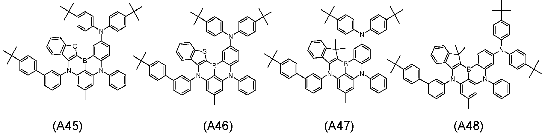
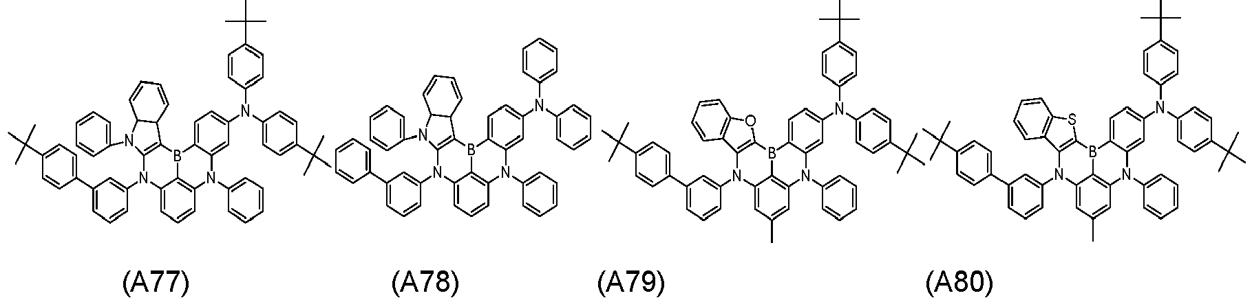
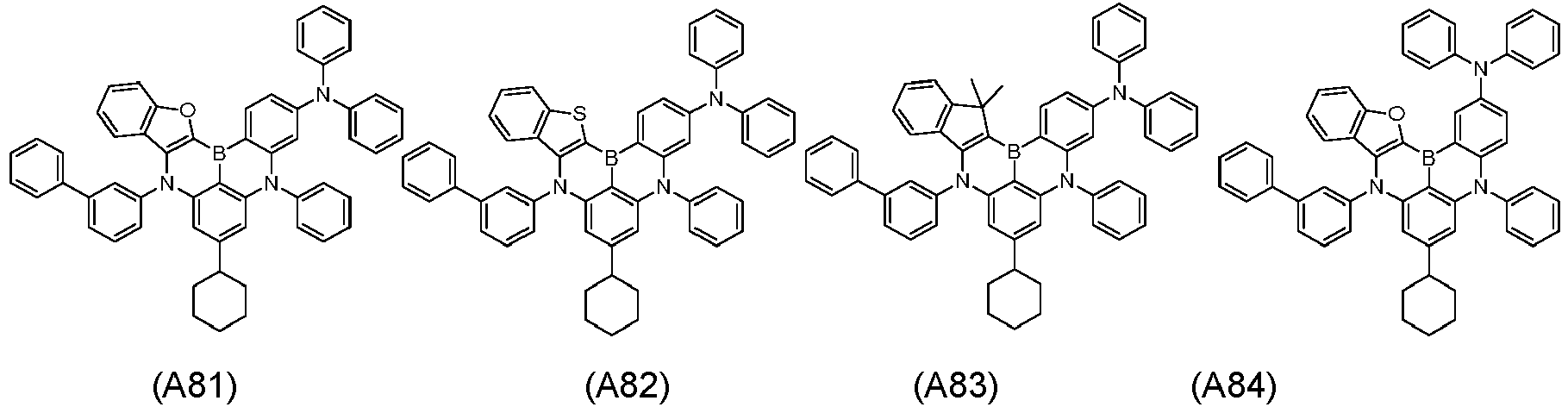
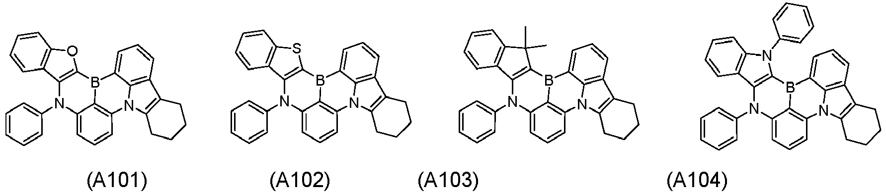
- polycyclic aromatic derivative represented by Formula A-1 or A-2 as a dopant compound employed in the light emitting layer as an organic layer of the organic electroluminescent device according to the present invention may be selected from the compounds of Formulae A1 to A176:
- the anthracene derivative represented by Formula B as a host compound employed in the light emitting layer as an organic layer of the organic electroluminescent device according to the present invention may be selected from the compounds of Formulae B1 to B16:
- the organic electroluminescent device of the present invention includes a first electrode, a second electrode, and one or more organic layers interposed between the first and second electrodes wherein at least one of the organic layers includes the compound represented by Formula A-1 or A-2 and the compound represented by Formula B.
- the compound represented by Formula A-1 or A-2 and the compound represented by Formula B are used as a dopant and a host in a light emitting layer of the device.
- the organic layers of the organic electroluminescent device according to the present invention may form a monolayer structure.
- the organic layers may have a multilayer laminate structure.
- the structure of the organic layers may include a hole injecting layer, a hole transport layer, a hole blocking layer, a light emitting layer, an electron blocking layer, an electron transport layer, and an electron injecting layer, but is not limited thereto.
- the number of the organic layers is not limited and may be increased or decreased. Preferred structures of the organic layers of the organic electroluminescent device according to the present invention will be explained in more detail in the Examples section that follows.
- the organic electroluminescent device may include a substrate, a first electrode (anode), one or more organic layers, a second electrode (cathode), and a capping layer formed under the first electrode (bottom emission type) or on the second electrode (top emission type).
- the organic electroluminescent device When the organic electroluminescent device is of a top emission type, light from the light emitting layer is emitted to the cathode and passes through the capping layer (CPL) formed using the compound of the present invention having a relatively high refractive index. The wavelength of the light is amplified in the capping layer, resulting in an increase in luminous efficiency. Also when the organic electroluminescent device is of a bottom emission type, the compound of the present invention can be employed in the capping layer to improve the luminous efficiency of the organic electroluminescent device based on the same principle.
- CPL capping layer
- the organic electroluminescent device of the present invention includes an anode, a hole transport layer, a light emitting layer, an electron transport layer, and a cathode.
- the organic electroluminescent device of the present invention may optionally further include a hole injecting layer between the anode and the hole transport layer and an electron injecting layer between the electron transport layer and the cathode. If necessary, the organic electroluminescent device of the present invention may further include one or two intermediate layers such as a hole blocking layer or an electron blocking layer.
- the organic electroluminescent device of the present invention may further include one or more organic layers such as a capping layer that have various functions depending on the desired characteristics of the device.
- the light emitting layer of the organic electroluminescent device further includes, as a host compound, an anthracene derivative represented by Formula C: wherein R 21 to R 28 are identical to or different from each other and are as defined for R 1 to R 4 in Formula A-1 or A-2, Ar 9 and Ar 10 are identical to or different from each other and are each independently selected from hydrogen, deuterium, substituted or unsubstituted C 1 -C 30 alkyl, substituted or unsubstituted C 6 -C 50 aryl, substituted or unsubstituted C 2 -C 30 alkenyl, substituted or unsubstituted C 2 -C 20 alkynyl, substituted or unsubstituted C 3 -C 30 cycloalkyl, substituted or unsubstituted C 5 -C 30 cycloalkenyl, substituted or unsubstituted C 2 -C 50 heteroaryl, substituted or unsubstituted C 2 -C 30
- Ar 9 in Formula C is represented by Formula C-1: wherein R 31 to R 35 are identical to or different from each other and are as defined for R 1 to R 4 in Formula A-1 or A-2, and each of R 31 to R 35 is optionally bonded to an adjacent substituent to form a saturated or unsaturated ring.
- the compound of Formula C employed in the organic electroluminescent device of the present invention may be specifically selected from the compounds of Formulae C1 to C48:
- the organic electroluminescent device of the present invention may further include a hole transport layer, an electron blocking layer, and a capping layer, each of which may include a compound represented by Formula D: wherein R 41 to R 43 are identical to or different from each other and are each independently selected from hydrogen, deuterium, substituted or unsubstituted C 1 -C 20 alkyl, substituted or unsubstituted C 6 -C 50 aryl, substituted or unsubstituted C 7 -C 50 arylalkyl, substituted or unsubstituted C 3 -C 30 cycloalkyl, substituted or unsubstituted C 1 -C 30 alkylsilyl, substituted or unsubstituted C 6 -C 30 arylsilyl, and halogen, L 31 to L 34 are identical to or different from each other and are each independently single bonds or selected from substituted or unsubstituted C 6 -C 50 arylene and substituted or unsubstituted C
- Ar 31 to Ar 34 is represented by Formula E: wherein R 51 to R 54 are identical to or different from each other and are each independently selected from hydrogen, deuterium, substituted or unsubstituted C 1 -C 30 alkyl, substituted or unsubstituted C 6 -C 50 aryl, substituted or unsubstituted C 2 -C 30 alkenyl, substituted or unsubstituted C 2 -C 20 alkynyl, substituted or unsubstituted C 3 -C 30 cycloalkyl, substituted or unsubstituted C 5 -C 30 cycloalkenyl, substituted or unsubstituted C 2 -C 50 heteroaryl, substituted or unsubstituted C 2 -C 30 heterocycloalkyl, substituted or unsubstituted C 1 -C 30 alkoxy, substituted or unsubstituted C 6 -C 30 aryloxy, substituted or unsub
- the compound of Formula D employed in the organic electroluminescent device of the present invention may be specifically selected from the compounds of Formulae D1 to D79:
- the compound of Formula D employed in the organic electroluminescent device of the present invention may be specifically selected from the compounds of Formulae D101 to D145:
- the organic electroluminescent device of the present invention may further include a hole transport layer, an electron blocking layer, and a capping layer, each of which may include a compound represented by Formula F: wherein R 61 to R 63 are identical to or different from each other and are each independently selected from hydrogen, deuterium, substituted or unsubstituted C 1 -C 30 alkyl, substituted or unsubstituted C 6 -C 50 aryl, substituted or unsubstituted C 2 -C 30 alkenyl, substituted or unsubstituted C 2 -C 20 alkynyl, substituted or unsubstituted C 3 -C 30 cycloalkyl, substituted or unsubstituted C 5 -C 30 cycloalkenyl, substituted or unsubstituted C 2 -C 50 heteroaryl, substituted or unsubstituted C 2 -C 30 heterocycloalkyl, substituted or unsubstituted C 1 -C 30
- the compound of Formula F employed in the organic electroluminescent device of the present invention may be specifically selected from the compounds of Formulae F1 to F33:
- a material for the anode is coated on the substrate to form the anode.
- the substrate may be any of those used in general electroluminescent devices.
- the substrate is preferably an organic substrate or a transparent plastic substrate that is excellent in transparency, surface smoothness, ease of handling, and waterproofness.
- a highly transparent and conductive metal oxide such as indium tin oxide (ITO), indium zinc oxide (IZO), tin oxide (SnO 2 ) or zinc oxide (ZnO), is used as the anode material.
- a material for the hole injecting layer is coated on the anode by vacuum thermal evaporation or spin coating to form the hole injecting layer. Then, a material for the hole transport layer is coated on the hole injecting layer by vacuum thermal evaporation or spin coating to form the hole transport layer.
- the material for the hole injecting layer is not specially limited so long as it is usually used in the art.
- specific examples of such materials include 4,4',4"-tris(2-naphthyl(phenyl)amino)triphenylamine (2-TNATA), N,N'-di(1-naphthyl)-N,N'-diphenylbenzidine (NPD), N,N'-diphenyl-N,N'-bis(3-methylphenyl)-1,1'-biphenyl-4,4'-diamine (TPD), and N,N'-diphenyl-N,N'-bis[4-(phenyl-m-tolylamino)phenyl]biphenyl-4,4'-diamine (DNTPD).
- the material for the hole transport layer is not specially limited so long as it is commonly used in the art.
- examples of such materials include N,N'-bis(3-methylphenyl)-N,N'-diphenyl-[1,1-biphenyl]-4,4'-diamine (TPD) and N,N'-di(naphthalen-1-yl)-N,N'-diphenylbenzidine ( ⁇ -NPD).
- a hole blocking layer may be optionally formed on the organic light emitting layer by vacuum thermal evaporation or spin coating.
- the hole blocking layer blocks holes from entering the cathode through the organic light emitting layer. This role of the hole blocking layer prevents the lifetime and efficiency of the device from deteriorating.
- a material having a very low highest occupied molecular orbital (HOMO) energy level is used for the hole blocking layer.
- the hole blocking material is not particularly limited so long as it has the ability to transport electrons and a higher ionization potential than the light emitting compound. Representative examples of suitable hole blocking materials include BAlq, BCP, and TPBI.
- Examples of materials for the hole blocking layer include, but are not limited to, BAlq, BCP, Bphen, TPBI, NTAZ, BeBq 2 , OXD-7, and Liq.
- the electron transport layer is deposited on the hole blocking layer by vacuum thermal evaporation or spin coating, and the electron injecting layer is formed thereon.
- a metal for the cathode is deposited on the electron injecting layer by vacuum thermal evaporation to form the cathode, completing the fabrication of the organic electroluminescent device.
- the metal for the formation of the cathode there may be used, for example, lithium (Li), magnesium (Mg), aluminum (Al), aluminum-lithium (Al-Li), calcium (Ca), magnesium-indium (Mg-In) or magnesium-silver (Mg-Ag).
- the organic electroluminescent device may be of top emission type.
- a transmissive material such as ITO or IZO, may be used to form the cathode.
- the material for the electron transport layer functions to stably transport electrons injected from the cathode.
- the electron transport material may be any of those known in the art and examples thereof include, but are not limited to, quinoline derivatives, particularly, tris(8-quinolinolate)aluminum (Alq3), TAZ, Balq, beryllium bis(benzoquinolin-10-olate (Bebq2), ADN, and oxadiazole derivatives, such as PBD, BMD, and BND.
- the light emitting layer of the organic electroluminescent device according to the present invention may further include a combination of various host and dopant materials in addition to the dopant compound of Formula A-1 or A-2 and the host compound of Formula B or C.
- Each of the organic layers can be formed by a monomolecular deposition or solution process.
- the material for each layer is evaporated under heat and vacuum or reduced pressure to form the layer in the form of a thin film.
- the solution process the material for each layer is mixed with a suitable solvent, and then the mixture is formed into a thin film by a suitable method, such as ink-jet printing, roll-to-roll coating, screen printing, spray coating, dip coating or spin coating.
- the organic electroluminescent device of the present invention can be used in a display or lighting system selected from flat panel displays, flexible displays, monochromatic flat panel lighting systems, white flat panel lighting systems, flexible monochromatic lighting systems, and flexible white lighting systems.
- 8-b (37.6 g, yield 78.4%) was synthesized in the same manner as in Synthesis Example 4-2, except that 8-a was used instead of diphenylamine.
- 8-c (31.2 g, yield 74.2%) was synthesized in the same manner as in Synthesis Example 1-3, except that 8-b and 4-tert-butylaniline were used instead of 1-bromo-3-iodobenzene and aniline.
- 8-f (21 g, yield 74.1%) was synthesized in the same manner as in Synthesis Example 1-4, except that 8-e and 8-c were used instead of 1-c and 1-b.
- Compound B2 (7.0 g, 66.1%) was synthesized in the same manner as in Synthesis Example 1-1, except that phenyl(d5)anthracene boronic acid was used instead of phenylanthracene boronic acid.
- Compound B3 (7.0 g, 66.1%) was synthesized in the same manner as in Synthesis Example 1-1, except that phenyl(d5)anthracene boronic acid and Intermediate 3-f were used instead of phenylanthracene boronic acid and 3-bromophenanthrene, respectively.
- Bromobenzene(d-5) (60.4 g, 0.373 mol) and 480 mL of tetrahydrofuran were placed in a 2 L round-bottom flask under a nitrogen atmosphere. The mixture was cooled to -78 °C and stirred. To the cooled solution was added dropwise n-butyllithium (223.6 mL, 0.357 mol). The resulting mixture was stirred at the same temperature for 1 h. To the reaction solution was added dropwise a solution of O-phthalaldehyde (20.0 g, 0.149 mol) in 100 mL of tetrahydrofuran, followed by stirring at room temperature.
- Compound B4 (5.6 g, 62.1%) was synthesized in the same manner as in Synthesis Example 1-1, except that Intermediate 4-d and Intermediate 4-c were used instead of phenylanthracene boronic acid and 3-bromophenanthrene, respectively.
- Compound B8 (7.0 g, 70.0%) was synthesized in the same manner as in Synthesis Example 1-1, except that Intermediate 4-d and Intermediate 6-a were used instead of phenylanthracene boronic acid and 3-bromophenanthrene, respectively.
- Compound B14 (5.1 g, 53.4%) was synthesized in the same manner as in Synthesis Example 1-1, except that Intermediate 8-d and Intermediate 9-a were used instead of phenylanthracene boronic acid and 3-bromophenanthrene, respectively.
- ITO glass was patterned to have a light emitting area of 2 mm ⁇ 2 mm, followed by cleaning. After the cleaned ITO glass was mounted in a vacuum chamber, the base pressure was adjusted to 1 ⁇ 10 -6 torr. DNTPD and the compound of Formula H were sequentially deposited on the ITO glass to form a 700 ⁇ thick hole injecting layer and a 250 ⁇ thick hole transport layer, respectively. A mixture of the corresponding host compound and the corresponding dopant compound (2 wt%) shown in Table 1 was used to form a 250 ⁇ thick light emitting layer. Thereafter, the compound of Formula E-1 and the compound of Formula E-2 in a ratio of 1:1 were used to form a 300 ⁇ thick electron transport layer on the light emitting layer.
- the compound of Formula E-1 was used to form a 5 ⁇ thick electron injecting layer on the electron transport layer.
- A1 was deposited on the electron injecting layer to form a 1000 ⁇ thick A1 electrode, completing the fabrication of an organic electroluminescent device.
- the luminescent properties of the organic electroluminescent device were measured at 0.4 mA.
- Organic electroluminescent devices were fabricated in the same manner as in Examples 1-21, except that BH1, BH2 or BH3 as a host compound and BD1, BD2, BD3 or BD4 as a dopant compound were used instead of the inventive compounds.
- the structures of BH1, BH2, BH3, BD1, BD2, BD3, and BD4 are as follow:
- the organic electroluminescent devices of Examples 1-21 each of which employed the compound of Formula B and the compound of Formula A-1 or A-2 as host and dopant materials for the light emitting layer, showed high color purities. Particularly, the organic electroluminescent devices of Examples 1-21 had greatly improved lifetimes.
Landscapes
- Chemical & Material Sciences (AREA)
- Physics & Mathematics (AREA)
- Engineering & Computer Science (AREA)
- Materials Engineering (AREA)
- Spectroscopy & Molecular Physics (AREA)
- Organic Chemistry (AREA)
- Optics & Photonics (AREA)
- Electroluminescent Light Sources (AREA)
Claims (16)
- Dispositif électroluminescent organique comprenant une première électrode, une deuxième électrode opposée à la première électrode, et une couche émettrice de lumière interposée entre les première et deuxième électrodes, la couche émettrice de lumière comprenant un composé représenté par la formule A-1 ou la formule A-2 :


- Dispositif électroluminescent organique selon la revendication 1, dans lequel au moins un de R6 à R13 dans la formule B est deutérium.
- Dispositif électroluminescent organique selon la revendication 1, dans lequel au moins un de R1 à R5 dans la formule B est deutérium et au moins un de R6 à R13 dans la formule B est deutérium
- Dispositif électroluminescent organique selon la revendication 1, dans lequel le composé de la formule A-1 ou A-2 a une structure représentée par la formule A-3 ou A-4 :


- Dispositif électroluminescent organique selon la revendication 1, dans lequel le composé de la formule A-1 ou A-2 a une structure représentée par la formule A-5 ou A-6 :


- Dispositif électroluminescent organique selon la revendication 1, dans lequel le composé représenté par la formule A-1 ou A-2 est choisi parmi les composés des formules A1 à A176 :









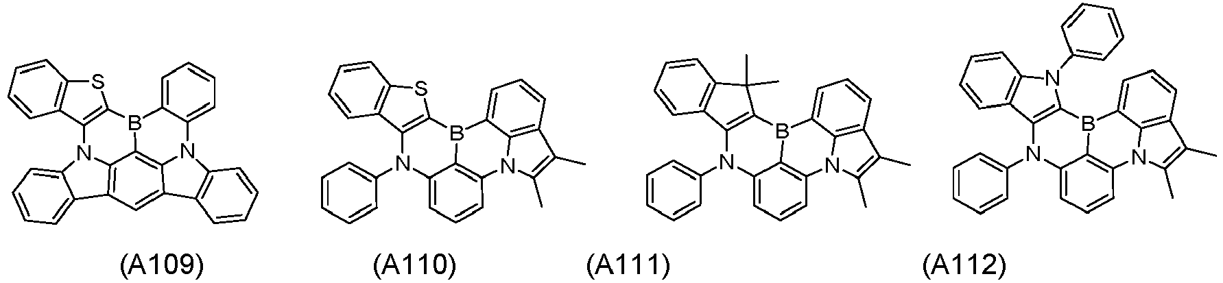


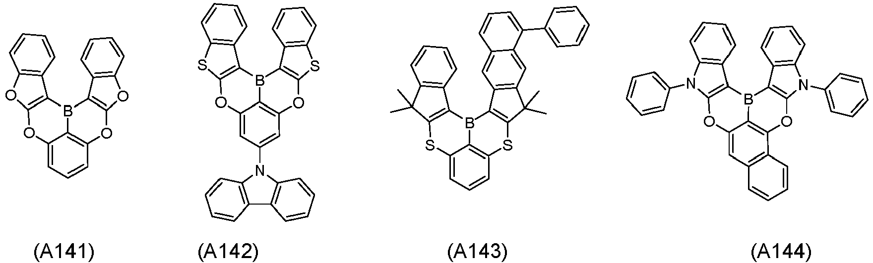


- Dispositif électroluminescent organique selon la revendication 1, dans lequel le composé représenté par la formule B est choisi parmi les composés des formules B1 à A16 :


- Dispositif électroluminescent organique selon la revendication 1, dans lequel la couche émettrice de lumière comprend en outre, en tant que composé hôte, un dérivé d'anthracène représenté par la formule C :

- Dispositif électroluminescent organique selon la revendication 8, dans lequel Ar9 dans la formule C est représenté par la formule C-1 :

- Dispositif électroluminescent organique selon la revendication 8, dans lequel le composé de la formule C est choisi parmi les composés des formules C1 à C48 :


- Dispositif électroluminescent organique selon la revendication 1, comprenant en outre une couche de transport de trous, une couche de blocage d'électrons, et une couche couvrante, dont chacun comprend un composé représenté par la formule D :

- Dispositif électroluminescent organique selon la revendication 11, dans lequel au moins un de Ar31 à Ar34 est représenté par la formule E :

- Dispositif électroluminescent organique selon la revendication 11, dans lequel le composé de la formule D est choisi parmi les composés des formules D1 à D79 :





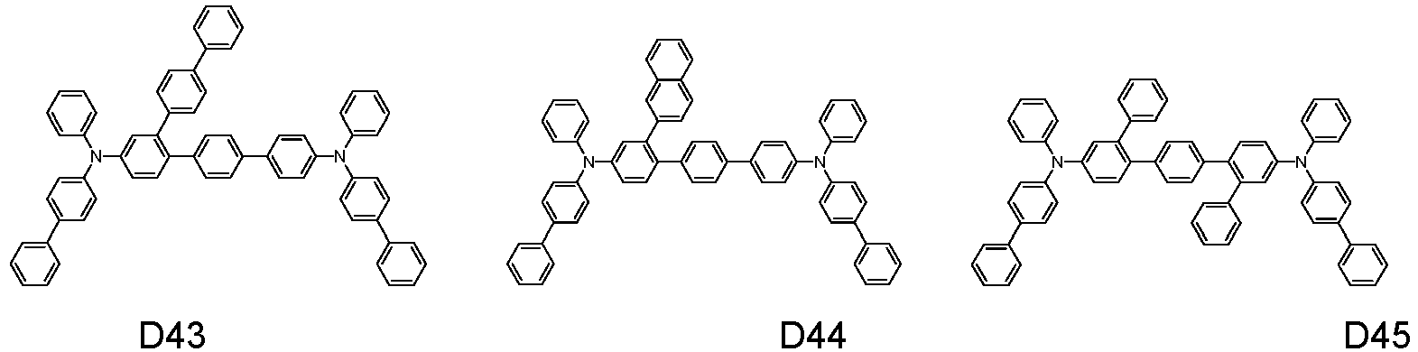


- Dispositif électroluminescent organique selon la revendication 11, dans lequel le composé de la formule D est choisi parmi les composés des formules D101 à D145 :



- Dispositif électroluminescent organique selon la revendication 1, comprenant en outre une couche de transport de trous, une couche de blocage d'électrons, et une couche couvrante, dont chacun comprend un composé représenté par la formule F :

- Dispositif électroluminescent organique selon la revendication 15, dans lequel le composé de la formule F est choisi parmi les composés des formules F1 à F33 :


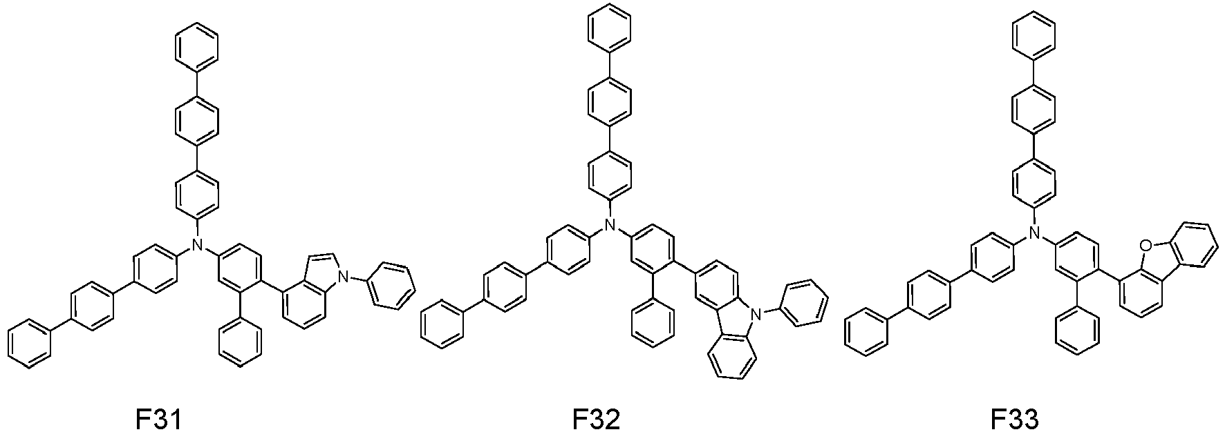
Applications Claiming Priority (2)
| Application Number | Priority Date | Filing Date | Title |
|---|---|---|---|
| KR20190069499 | 2019-06-12 | ||
| KR1020200050117A KR102191018B1 (ko) | 2019-06-12 | 2020-04-24 | 유기발광소자 |
Publications (2)
| Publication Number | Publication Date |
|---|---|
| EP3750971A1 EP3750971A1 (fr) | 2020-12-16 |
| EP3750971B1 true EP3750971B1 (fr) | 2023-02-22 |
Family
ID=71094125
Family Applications (1)
| Application Number | Title | Priority Date | Filing Date |
|---|---|---|---|
| EP20179629.9A Active EP3750971B1 (fr) | 2019-06-12 | 2020-06-12 | Dispositif électroluminescent organique |
Country Status (4)
| Country | Link |
|---|---|
| US (1) | US12552984B2 (fr) |
| EP (1) | EP3750971B1 (fr) |
| JP (1) | JP7094035B2 (fr) |
| CN (1) | CN112086568B (fr) |
Families Citing this family (26)
| Publication number | Priority date | Publication date | Assignee | Title |
|---|---|---|---|---|
| CN113795497B (zh) * | 2019-11-29 | 2024-04-26 | 株式会社Lg化学 | 化合物和包含其的有机发光器件 |
| US20220384733A1 (en) * | 2019-11-29 | 2022-12-01 | Lg Chem, Ltd. | Organic light emitting device |
| KR102855088B1 (ko) | 2019-12-26 | 2025-09-04 | 이데미쓰 고산 가부시키가이샤 | 유기 일렉트로루미네센스 소자, 조성물, 분체, 전자 기기, 및 신규 화합물 |
| US12565509B2 (en) | 2020-01-22 | 2026-03-03 | Sfc Co., Ltd | Polycyclic aromatic derivative compound and organic light-emitting device using same |
| KR102847487B1 (ko) * | 2020-06-11 | 2025-08-21 | 삼성디스플레이 주식회사 | 유기 전계 발광 소자 및 유기 전계 발광 소자용 축합 다환 화합물 |
| EP4202010A4 (fr) | 2020-09-04 | 2024-11-13 | SFC Co., Ltd. | Composé dérivé aromatique polycyclique et dispositif électroluminescent organique l'utilisant |
| KR20220093849A (ko) | 2020-12-28 | 2022-07-05 | 엘지디스플레이 주식회사 | 유기발광장치 |
| KR102886337B1 (ko) | 2020-12-28 | 2025-11-13 | 엘지디스플레이 주식회사 | 유기발광장치 |
| KR20220094620A (ko) | 2020-12-29 | 2022-07-06 | 엘지디스플레이 주식회사 | 발광 화합물 및 이를 포함하는 유기발광장치 |
| EP4023653A1 (fr) * | 2020-12-29 | 2022-07-06 | LG Display Co., Ltd. | Composé électroluminescent et dispositif électroluminescent organique le comprenant |
| WO2022144019A1 (fr) * | 2021-01-04 | 2022-07-07 | 浙江光昊光电科技有限公司 | Mélange organique et application de celui-ci dans un dispositif électronique organique |
| CN116547255A (zh) * | 2021-01-22 | 2023-08-04 | 株式会社Lg化学 | 用于制备氘化蒽化合物的方法、反应组合物、氘化蒽化合物和组合物 |
| TWI835062B (zh) * | 2021-02-04 | 2024-03-11 | 南韓商Lg化學股份有限公司 | 氘代蒽化合物的製備方法、反應組成物、氘代蒽化合物以及組成物 |
| CN113045595A (zh) * | 2021-02-05 | 2021-06-29 | 吉林奥来德光电材料股份有限公司 | 多环芳族系化合物、其制备方法、发光材料、发光层和有机电致发光器件 |
| CN112961174A (zh) * | 2021-02-05 | 2021-06-15 | 吉林奥来德光电材料股份有限公司 | 一种多环芳族化合物及其制备方法和应用 |
| US12543493B2 (en) * | 2021-03-08 | 2026-02-03 | Sfc Co., Ltd. | Organic light-emitting device |
| CN115073503A (zh) * | 2021-03-12 | 2022-09-20 | Sfc株式会社 | 多环化合物和使用其的有机电致发光器件 |
| CN115073502A (zh) * | 2021-03-12 | 2022-09-20 | Sfc株式会社 | 多环化合物和使用其的有机电致发光器件 |
| CN114380854B (zh) * | 2022-01-27 | 2024-04-16 | 武汉天马微电子有限公司 | 一种有机化合物、热活化延迟荧光材料及其应用 |
| KR20240145454A (ko) * | 2022-02-03 | 2024-10-07 | 삼성디스플레이 주식회사 | 광전자 소자 |
| CN114989200B (zh) * | 2022-04-29 | 2024-06-04 | 广州追光科技有限公司 | 含硼氮化合物及其在有机电子器件中的应用 |
| CN117327106B (zh) * | 2022-06-21 | 2025-09-23 | 江苏三月科技股份有限公司 | 一种含硼有机化合物及包含其的有机电致发光器件 |
| CN115124558B (zh) * | 2022-07-08 | 2024-08-13 | 闽都创新实验室 | 一种芳基硼酸酯类化合物的制备方法及其应用 |
| CN115925731A (zh) * | 2022-12-12 | 2023-04-07 | 吉林奥来德光电材料股份有限公司 | 一种含硼有机电致发光材料及其制备方法与应用 |
| WO2025095128A1 (fr) * | 2023-11-01 | 2025-05-08 | 出光興産株式会社 | Élément électroluminescent organique et dispositif électronique |
| CN117567491A (zh) * | 2023-11-22 | 2024-02-20 | 奥盖尼克材料(苏州)有限公司 | 一种蓝色发光分子材料的合成方法 |
Family Cites Families (17)
| Publication number | Priority date | Publication date | Assignee | Title |
|---|---|---|---|---|
| TWI636056B (zh) | 2014-02-18 | 2018-09-21 | 學校法人關西學院 | 多環芳香族化合物及其製造方法、有機元件用材料及其應用 |
| US20150243895A1 (en) | 2014-02-26 | 2015-08-27 | Samsung Display Co., Ltd. | Compound and organic light-emitting device including the same |
| WO2016021923A2 (fr) | 2014-08-04 | 2016-02-11 | 주식회사 동진쎄미켐 | Nouveau composé et dispositif électroluminescent organique le contenant |
| TWI688137B (zh) | 2015-03-24 | 2020-03-11 | 學校法人關西學院 | 有機電場發光元件、顯示裝置以及照明裝置 |
| US10367147B2 (en) | 2015-05-27 | 2019-07-30 | Samsung Display Co., Ltd. | Organic light-emitting device |
| JP6634838B2 (ja) | 2016-01-12 | 2020-01-22 | コニカミノルタ株式会社 | 電子デバイス材料、有機エレクトロルミネッセンス素子、表示装置、及び、照明装置 |
| KR20180134331A (ko) | 2016-04-22 | 2018-12-18 | 호도가야 가가쿠 고교 가부시키가이샤 | 유기 일렉트로 루미네센스 소자 |
| KR20220084200A (ko) | 2016-04-26 | 2022-06-21 | 가꼬우 호징 관세이 가쿠잉 | 유기 전계 발광 소자 |
| KR102125343B1 (ko) | 2017-01-10 | 2020-06-24 | 에스에프씨주식회사 | 고효율을 갖는 유기 발광 소자 |
| KR102053324B1 (ko) | 2017-05-02 | 2019-12-06 | 주식회사 엘지화학 | 신규한 화합물 및 이를 이용한 유기발광 소자 |
| JP7044547B2 (ja) * | 2017-12-28 | 2022-03-30 | 出光興産株式会社 | 新規化合物及び有機エレクトロルミネッセンス素子 |
| WO2019164331A1 (fr) * | 2018-02-23 | 2019-08-29 | 주식회사 엘지화학 | Composé hétérocyclique et dispositif électroluminescent organique le comprenant |
| KR102094830B1 (ko) | 2018-11-30 | 2020-03-30 | 에스에프씨 주식회사 | 다환 방향족 유도체 화합물 및 이를 이용한 유기발광소자 |
| US11985891B2 (en) * | 2018-11-30 | 2024-05-14 | Sfc Co., Ltd. | Polycyclic aromatic compounds and organic electroluminescent devices using the same |
| KR102725258B1 (ko) * | 2018-12-18 | 2024-11-04 | 삼성디스플레이 주식회사 | 붕소 및 질소를 포함하는 헤테로고리 화합물을 포함하는 유기 발광 소자 |
| CN118742080A (zh) * | 2019-05-15 | 2024-10-01 | 株式会社Lg化学 | 有机发光器件 |
| US12284917B2 (en) * | 2019-06-10 | 2025-04-22 | Sfc Co., Ltd. | Compound for organic light-emitting diode and organic light-emitting diode comprising same |
-
2020
- 2020-06-03 US US16/891,658 patent/US12552984B2/en active Active
- 2020-06-11 JP JP2020101921A patent/JP7094035B2/ja active Active
- 2020-06-11 CN CN202010529263.7A patent/CN112086568B/zh active Active
- 2020-06-12 EP EP20179629.9A patent/EP3750971B1/fr active Active
Also Published As
| Publication number | Publication date |
|---|---|
| CN112086568A (zh) | 2020-12-15 |
| CN112086568B (zh) | 2024-01-30 |
| US20200395553A1 (en) | 2020-12-17 |
| EP3750971A1 (fr) | 2020-12-16 |
| US12552984B2 (en) | 2026-02-17 |
| JP2020202377A (ja) | 2020-12-17 |
| JP7094035B2 (ja) | 2022-07-01 |
Similar Documents
| Publication | Publication Date | Title |
|---|---|---|
| EP3750971B1 (fr) | Dispositif électroluminescent organique | |
| EP3660024B1 (fr) | Composés aromatiques polycycliques et dispositifs électroluminescents organiques utilisant ceux-ci | |
| EP3792989B1 (fr) | Diode électroluminescente organique comprenant des composés de bore | |
| EP4131456B1 (fr) | Dispositif électroluminescent organique | |
| EP4122937A1 (fr) | Composé aromatique polycyclique et dispositif électroluminescent organique l'utilisant | |
| EP4108667B1 (fr) | Composé dérivé polycyclique aromatique et dispositif électroluminescent organique l'utilisant | |
| EP4123737B1 (fr) | Dispositif électroluminescent organique utilisant des composés aromatiques polycycliques | |
| EP4135005B1 (fr) | Dispositif électroluminescent organique | |
| EP4123736B1 (fr) | Dispositif organique électroluminescent utilisant des composés dérivés aromatiques polycycliques | |
| KR102352838B1 (ko) | 다환 방향족 유도체 화합물 및 이를 이용한 유기발광소자 | |
| KR20220048445A (ko) | 보론 함유 다환 고리 화합물 및 이를 이용한 유기발광소자 | |
| EP4234563A1 (fr) | Composé polycyclique et dispositif électroluminescent organique utilisant un tel composé | |
| KR20220081251A (ko) | 유기발광 화합물 및 이를 포함하는 유기발광소자 | |
| KR20210117975A (ko) | 다환 방향족 유도체 화합물을 이용한 유기발광소자 | |
| EP4011872A1 (fr) | Composé électroluminescent organique et dispositif électroluminescent organique le comprenant | |
| EP4299568A1 (fr) | Composé électroluminescent organique et dispositif électroluminescent organique le comprenant | |
| EP4138537A1 (fr) | Dispositif électroluminescent organique | |
| EP3998321B1 (fr) | Composé électroluminescent organique et dispositif électroluminescent organique | |
| EP4119554A1 (fr) | Composé amine ayant un cycle fusionné et dispositif électroluminescent organique le comprenant | |
| KR20230013803A (ko) | 다환 고리 화합물 및 이를 이용한 유기발광소자 | |
| KR102645771B1 (ko) | 유기발광 화합물 및 이를 포함하는 유기발광소자 | |
| KR102946002B1 (ko) | 다환 고리 화합물 및 이를 이용한 유기발광소자 | |
| EP4300608A1 (fr) | Dispositif électroluminescent organique | |
| KR20240133931A (ko) | 다환 고리 화합물 및 이를 포함하는 유기발광소자 |
Legal Events
| Date | Code | Title | Description |
|---|---|---|---|
| PUAI | Public reference made under article 153(3) epc to a published international application that has entered the european phase |
Free format text: ORIGINAL CODE: 0009012 |
|
| STAA | Information on the status of an ep patent application or granted ep patent |
Free format text: STATUS: THE APPLICATION HAS BEEN PUBLISHED |
|
| AK | Designated contracting states |
Kind code of ref document: A1 Designated state(s): AL AT BE BG CH CY CZ DE DK EE ES FI FR GB GR HR HU IE IS IT LI LT LU LV MC MK MT NL NO PL PT RO RS SE SI SK SM TR |
|
| AX | Request for extension of the european patent |
Extension state: BA ME |
|
| STAA | Information on the status of an ep patent application or granted ep patent |
Free format text: STATUS: REQUEST FOR EXAMINATION WAS MADE |
|
| 17P | Request for examination filed |
Effective date: 20210611 |
|
| RBV | Designated contracting states (corrected) |
Designated state(s): AL AT BE BG CH CY CZ DE DK EE ES FI FR GB GR HR HU IE IS IT LI LT LU LV MC MK MT NL NO PL PT RO RS SE SI SK SM TR |
|
| GRAJ | Information related to disapproval of communication of intention to grant by the applicant or resumption of examination proceedings by the epo deleted |
Free format text: ORIGINAL CODE: EPIDOSDIGR1 |
|
| GRAP | Despatch of communication of intention to grant a patent |
Free format text: ORIGINAL CODE: EPIDOSNIGR1 |
|
| GRAP | Despatch of communication of intention to grant a patent |
Free format text: ORIGINAL CODE: EPIDOSNIGR1 |
|
| STAA | Information on the status of an ep patent application or granted ep patent |
Free format text: STATUS: GRANT OF PATENT IS INTENDED |
|
| RIC1 | Information provided on ipc code assigned before grant |
Ipc: H01L 51/00 20060101ALI20220812BHEP Ipc: H01L 51/50 20060101ALI20220812BHEP Ipc: C09K 11/06 20060101AFI20220812BHEP |
|
| INTG | Intention to grant announced |
Effective date: 20220920 |
|
| GRAS | Grant fee paid |
Free format text: ORIGINAL CODE: EPIDOSNIGR3 |
|
| GRAA | (expected) grant |
Free format text: ORIGINAL CODE: 0009210 |
|
| STAA | Information on the status of an ep patent application or granted ep patent |
Free format text: STATUS: THE PATENT HAS BEEN GRANTED |
|
| AK | Designated contracting states |
Kind code of ref document: B1 Designated state(s): AL AT BE BG CH CY CZ DE DK EE ES FI FR GB GR HR HU IE IS IT LI LT LU LV MC MK MT NL NO PL PT RO RS SE SI SK SM TR |
|
| REG | Reference to a national code |
Ref country code: GB Ref legal event code: FG4D |
|
| REG | Reference to a national code |
Ref country code: CH Ref legal event code: EP |
|
| REG | Reference to a national code |
Ref country code: DE Ref legal event code: R096 Ref document number: 602020008217 Country of ref document: DE |
|
| REG | Reference to a national code |
Ref country code: AT Ref legal event code: REF Ref document number: 1549535 Country of ref document: AT Kind code of ref document: T Effective date: 20230315 Ref country code: IE Ref legal event code: FG4D |
|
| REG | Reference to a national code |
Ref country code: NL Ref legal event code: FP |
|
| REG | Reference to a national code |
Ref country code: LT Ref legal event code: MG9D |
|
| P01 | Opt-out of the competence of the unified patent court (upc) registered |
Effective date: 20230526 |
|
| REG | Reference to a national code |
Ref country code: AT Ref legal event code: MK05 Ref document number: 1549535 Country of ref document: AT Kind code of ref document: T Effective date: 20230222 |
|
| PG25 | Lapsed in a contracting state [announced via postgrant information from national office to epo] |
Ref country code: RS Free format text: LAPSE BECAUSE OF FAILURE TO SUBMIT A TRANSLATION OF THE DESCRIPTION OR TO PAY THE FEE WITHIN THE PRESCRIBED TIME-LIMIT Effective date: 20230222 Ref country code: PT Free format text: LAPSE BECAUSE OF FAILURE TO SUBMIT A TRANSLATION OF THE DESCRIPTION OR TO PAY THE FEE WITHIN THE PRESCRIBED TIME-LIMIT Effective date: 20230622 Ref country code: NO Free format text: LAPSE BECAUSE OF FAILURE TO SUBMIT A TRANSLATION OF THE DESCRIPTION OR TO PAY THE FEE WITHIN THE PRESCRIBED TIME-LIMIT Effective date: 20230522 Ref country code: LV Free format text: LAPSE BECAUSE OF FAILURE TO SUBMIT A TRANSLATION OF THE DESCRIPTION OR TO PAY THE FEE WITHIN THE PRESCRIBED TIME-LIMIT Effective date: 20230222 Ref country code: LT Free format text: LAPSE BECAUSE OF FAILURE TO SUBMIT A TRANSLATION OF THE DESCRIPTION OR TO PAY THE FEE WITHIN THE PRESCRIBED TIME-LIMIT Effective date: 20230222 Ref country code: HR Free format text: LAPSE BECAUSE OF FAILURE TO SUBMIT A TRANSLATION OF THE DESCRIPTION OR TO PAY THE FEE WITHIN THE PRESCRIBED TIME-LIMIT Effective date: 20230222 Ref country code: ES Free format text: LAPSE BECAUSE OF FAILURE TO SUBMIT A TRANSLATION OF THE DESCRIPTION OR TO PAY THE FEE WITHIN THE PRESCRIBED TIME-LIMIT Effective date: 20230222 Ref country code: AT Free format text: LAPSE BECAUSE OF FAILURE TO SUBMIT A TRANSLATION OF THE DESCRIPTION OR TO PAY THE FEE WITHIN THE PRESCRIBED TIME-LIMIT Effective date: 20230222 |
|
| PG25 | Lapsed in a contracting state [announced via postgrant information from national office to epo] |
Ref country code: SE Free format text: LAPSE BECAUSE OF FAILURE TO SUBMIT A TRANSLATION OF THE DESCRIPTION OR TO PAY THE FEE WITHIN THE PRESCRIBED TIME-LIMIT Effective date: 20230222 Ref country code: PL Free format text: LAPSE BECAUSE OF FAILURE TO SUBMIT A TRANSLATION OF THE DESCRIPTION OR TO PAY THE FEE WITHIN THE PRESCRIBED TIME-LIMIT Effective date: 20230222 Ref country code: IS Free format text: LAPSE BECAUSE OF FAILURE TO SUBMIT A TRANSLATION OF THE DESCRIPTION OR TO PAY THE FEE WITHIN THE PRESCRIBED TIME-LIMIT Effective date: 20230622 Ref country code: GR Free format text: LAPSE BECAUSE OF FAILURE TO SUBMIT A TRANSLATION OF THE DESCRIPTION OR TO PAY THE FEE WITHIN THE PRESCRIBED TIME-LIMIT Effective date: 20230523 Ref country code: FI Free format text: LAPSE BECAUSE OF FAILURE TO SUBMIT A TRANSLATION OF THE DESCRIPTION OR TO PAY THE FEE WITHIN THE PRESCRIBED TIME-LIMIT Effective date: 20230222 |
|
| PG25 | Lapsed in a contracting state [announced via postgrant information from national office to epo] |
Ref country code: SM Free format text: LAPSE BECAUSE OF FAILURE TO SUBMIT A TRANSLATION OF THE DESCRIPTION OR TO PAY THE FEE WITHIN THE PRESCRIBED TIME-LIMIT Effective date: 20230222 Ref country code: RO Free format text: LAPSE BECAUSE OF FAILURE TO SUBMIT A TRANSLATION OF THE DESCRIPTION OR TO PAY THE FEE WITHIN THE PRESCRIBED TIME-LIMIT Effective date: 20230222 Ref country code: EE Free format text: LAPSE BECAUSE OF FAILURE TO SUBMIT A TRANSLATION OF THE DESCRIPTION OR TO PAY THE FEE WITHIN THE PRESCRIBED TIME-LIMIT Effective date: 20230222 Ref country code: DK Free format text: LAPSE BECAUSE OF FAILURE TO SUBMIT A TRANSLATION OF THE DESCRIPTION OR TO PAY THE FEE WITHIN THE PRESCRIBED TIME-LIMIT Effective date: 20230222 Ref country code: CZ Free format text: LAPSE BECAUSE OF FAILURE TO SUBMIT A TRANSLATION OF THE DESCRIPTION OR TO PAY THE FEE WITHIN THE PRESCRIBED TIME-LIMIT Effective date: 20230222 |
|
| REG | Reference to a national code |
Ref country code: DE Ref legal event code: R097 Ref document number: 602020008217 Country of ref document: DE |
|
| PG25 | Lapsed in a contracting state [announced via postgrant information from national office to epo] |
Ref country code: SK Free format text: LAPSE BECAUSE OF FAILURE TO SUBMIT A TRANSLATION OF THE DESCRIPTION OR TO PAY THE FEE WITHIN THE PRESCRIBED TIME-LIMIT Effective date: 20230222 |
|
| PLBE | No opposition filed within time limit |
Free format text: ORIGINAL CODE: 0009261 |
|
| STAA | Information on the status of an ep patent application or granted ep patent |
Free format text: STATUS: NO OPPOSITION FILED WITHIN TIME LIMIT |
|
| PG25 | Lapsed in a contracting state [announced via postgrant information from national office to epo] |
Ref country code: MC Free format text: LAPSE BECAUSE OF FAILURE TO SUBMIT A TRANSLATION OF THE DESCRIPTION OR TO PAY THE FEE WITHIN THE PRESCRIBED TIME-LIMIT Effective date: 20230222 |
|
| 26N | No opposition filed |
Effective date: 20231123 |
|
| PG25 | Lapsed in a contracting state [announced via postgrant information from national office to epo] |
Ref country code: SI Free format text: LAPSE BECAUSE OF FAILURE TO SUBMIT A TRANSLATION OF THE DESCRIPTION OR TO PAY THE FEE WITHIN THE PRESCRIBED TIME-LIMIT Effective date: 20230222 Ref country code: MC Free format text: LAPSE BECAUSE OF FAILURE TO SUBMIT A TRANSLATION OF THE DESCRIPTION OR TO PAY THE FEE WITHIN THE PRESCRIBED TIME-LIMIT Effective date: 20230222 |
|
| REG | Reference to a national code |
Ref country code: CH Ref legal event code: PL |
|
| REG | Reference to a national code |
Ref country code: BE Ref legal event code: MM Effective date: 20230630 |
|
| PG25 | Lapsed in a contracting state [announced via postgrant information from national office to epo] |
Ref country code: LU Free format text: LAPSE BECAUSE OF NON-PAYMENT OF DUE FEES Effective date: 20230612 |
|
| REG | Reference to a national code |
Ref country code: IE Ref legal event code: MM4A |
|
| PG25 | Lapsed in a contracting state [announced via postgrant information from national office to epo] |
Ref country code: LU Free format text: LAPSE BECAUSE OF NON-PAYMENT OF DUE FEES Effective date: 20230612 |
|
| PG25 | Lapsed in a contracting state [announced via postgrant information from national office to epo] |
Ref country code: IE Free format text: LAPSE BECAUSE OF NON-PAYMENT OF DUE FEES Effective date: 20230612 |
|
| PG25 | Lapsed in a contracting state [announced via postgrant information from national office to epo] |
Ref country code: IE Free format text: LAPSE BECAUSE OF NON-PAYMENT OF DUE FEES Effective date: 20230612 Ref country code: CH Free format text: LAPSE BECAUSE OF NON-PAYMENT OF DUE FEES Effective date: 20230630 |
|
| PG25 | Lapsed in a contracting state [announced via postgrant information from national office to epo] |
Ref country code: BE Free format text: LAPSE BECAUSE OF NON-PAYMENT OF DUE FEES Effective date: 20230630 |
|
| PG25 | Lapsed in a contracting state [announced via postgrant information from national office to epo] |
Ref country code: BG Free format text: LAPSE BECAUSE OF FAILURE TO SUBMIT A TRANSLATION OF THE DESCRIPTION OR TO PAY THE FEE WITHIN THE PRESCRIBED TIME-LIMIT Effective date: 20230222 |
|
| PG25 | Lapsed in a contracting state [announced via postgrant information from national office to epo] |
Ref country code: BG Free format text: LAPSE BECAUSE OF FAILURE TO SUBMIT A TRANSLATION OF THE DESCRIPTION OR TO PAY THE FEE WITHIN THE PRESCRIBED TIME-LIMIT Effective date: 20230222 |
|
| PGFP | Annual fee paid to national office [announced via postgrant information from national office to epo] |
Ref country code: DE Payment date: 20250620 Year of fee payment: 6 |
|
| PGFP | Annual fee paid to national office [announced via postgrant information from national office to epo] |
Ref country code: GB Payment date: 20250620 Year of fee payment: 6 |
|
| PGFP | Annual fee paid to national office [announced via postgrant information from national office to epo] |
Ref country code: NL Payment date: 20250618 Year of fee payment: 6 |
|
| PGFP | Annual fee paid to national office [announced via postgrant information from national office to epo] |
Ref country code: FR Payment date: 20250624 Year of fee payment: 6 |
|
| PG25 | Lapsed in a contracting state [announced via postgrant information from national office to epo] |
Ref country code: CY Free format text: LAPSE BECAUSE OF FAILURE TO SUBMIT A TRANSLATION OF THE DESCRIPTION OR TO PAY THE FEE WITHIN THE PRESCRIBED TIME-LIMIT; INVALID AB INITIO Effective date: 20200612 |
|
| PG25 | Lapsed in a contracting state [announced via postgrant information from national office to epo] |
Ref country code: HU Free format text: LAPSE BECAUSE OF FAILURE TO SUBMIT A TRANSLATION OF THE DESCRIPTION OR TO PAY THE FEE WITHIN THE PRESCRIBED TIME-LIMIT; INVALID AB INITIO Effective date: 20200612 |
|
| PGFP | Annual fee paid to national office [announced via postgrant information from national office to epo] |
Ref country code: IT Payment date: 20250630 Year of fee payment: 6 |
|
| PG25 | Lapsed in a contracting state [announced via postgrant information from national office to epo] |
Ref country code: TR Free format text: LAPSE BECAUSE OF FAILURE TO SUBMIT A TRANSLATION OF THE DESCRIPTION OR TO PAY THE FEE WITHIN THE PRESCRIBED TIME-LIMIT Effective date: 20230222 |