EP3751081A1 - Charnière de montage rapide ainsi qu'armoire en tôle dotée de la charnière de montage rapide - Google Patents
Charnière de montage rapide ainsi qu'armoire en tôle dotée de la charnière de montage rapide Download PDFInfo
- Publication number
- EP3751081A1 EP3751081A1 EP20179539.0A EP20179539A EP3751081A1 EP 3751081 A1 EP3751081 A1 EP 3751081A1 EP 20179539 A EP20179539 A EP 20179539A EP 3751081 A1 EP3751081 A1 EP 3751081A1
- Authority
- EP
- European Patent Office
- Prior art keywords
- section
- hinge
- snap
- plug
- quick
- Prior art date
- Legal status (The legal status is an assumption and is not a legal conclusion. Google has not performed a legal analysis and makes no representation as to the accuracy of the status listed.)
- Granted
Links
Images




Classifications
-
- E—FIXED CONSTRUCTIONS
- E05—LOCKS; KEYS; WINDOW OR DOOR FITTINGS; SAFES
- E05D—HINGES OR SUSPENSION DEVICES FOR DOORS, WINDOWS OR WINGS
- E05D5/00—Construction of single parts, e.g. the parts for attachment
- E05D5/02—Parts for attachment, e.g. flaps
- E05D5/0215—Parts for attachment, e.g. flaps for attachment to profile members or the like
-
- E—FIXED CONSTRUCTIONS
- E05—LOCKS; KEYS; WINDOW OR DOOR FITTINGS; SAFES
- E05D—HINGES OR SUSPENSION DEVICES FOR DOORS, WINDOWS OR WINGS
- E05D7/00—Hinges or pivots of special construction
- E05D7/10—Hinges or pivots of special construction to allow easy separation or connection of the parts at the hinge axis
- E05D7/1005—Hinges or pivots of special construction to allow easy separation or connection of the parts at the hinge axis by axially moving free pins, balls or sockets
- E05D7/1022—Hinges or pivots of special construction to allow easy separation or connection of the parts at the hinge axis by axially moving free pins, balls or sockets with snap-fitted pins
-
- E—FIXED CONSTRUCTIONS
- E05—LOCKS; KEYS; WINDOW OR DOOR FITTINGS; SAFES
- E05D—HINGES OR SUSPENSION DEVICES FOR DOORS, WINDOWS OR WINGS
- E05D7/00—Hinges or pivots of special construction
- E05D7/12—Hinges or pivots of special construction to allow easy detachment of the hinge from the wing or the frame
-
- A—HUMAN NECESSITIES
- A47—FURNITURE; DOMESTIC ARTICLES OR APPLIANCES; COFFEE MILLS; SPICE MILLS; SUCTION CLEANERS IN GENERAL
- A47B—TABLES; DESKS; OFFICE FURNITURE; CABINETS; DRAWERS; GENERAL DETAILS OF FURNITURE
- A47B47/00—Cabinets, racks or shelf units, characterised by features related to dismountability or building-up from elements
- A47B47/02—Cabinets, racks or shelf units, characterised by features related to dismountability or building-up from elements made of metal only
-
- E—FIXED CONSTRUCTIONS
- E05—LOCKS; KEYS; WINDOW OR DOOR FITTINGS; SAFES
- E05D—HINGES OR SUSPENSION DEVICES FOR DOORS, WINDOWS OR WINGS
- E05D5/00—Construction of single parts, e.g. the parts for attachment
- E05D5/02—Parts for attachment, e.g. flaps
- E05D5/06—Bent flaps
-
- E—FIXED CONSTRUCTIONS
- E05—LOCKS; KEYS; WINDOW OR DOOR FITTINGS; SAFES
- E05Y—INDEXING SCHEME ASSOCIATED WITH SUBCLASSES E05D AND E05F, RELATING TO CONSTRUCTION ELEMENTS, ELECTRIC CONTROL, POWER SUPPLY, POWER SIGNAL OR TRANSMISSION, USER INTERFACES, MOUNTING OR COUPLING, DETAILS, ACCESSORIES, AUXILIARY OPERATIONS NOT OTHERWISE PROVIDED FOR, APPLICATION THEREOF
- E05Y2600/00—Mounting or coupling arrangements for elements provided for in this subclass
- E05Y2600/50—Mounting methods; Positioning
- E05Y2600/52—Toolless
- E05Y2600/53—Snapping
-
- E—FIXED CONSTRUCTIONS
- E05—LOCKS; KEYS; WINDOW OR DOOR FITTINGS; SAFES
- E05Y—INDEXING SCHEME ASSOCIATED WITH SUBCLASSES E05D AND E05F, RELATING TO CONSTRUCTION ELEMENTS, ELECTRIC CONTROL, POWER SUPPLY, POWER SIGNAL OR TRANSMISSION, USER INTERFACES, MOUNTING OR COUPLING, DETAILS, ACCESSORIES, AUXILIARY OPERATIONS NOT OTHERWISE PROVIDED FOR, APPLICATION THEREOF
- E05Y2900/00—Application of doors, windows, wings or fittings thereof
- E05Y2900/20—Application of doors, windows, wings or fittings thereof for furniture, e.g. cabinets
- E05Y2900/208—Application of doors, windows, wings or fittings thereof for furniture, e.g. cabinets for metal cabinets
Definitions
- the invention relates to a quick assembly hinge with the features of the preamble of claim 1. Furthermore, the invention relates to a sheet metal cabinet with the quick assembly hinge.
- Quick-assembly hinges serve as fittings for flaps, doors, etc. on furniture, containers, etc., with such a quick-assembly hinge being able to be fixed by means of a snap-on fastening for quick and easy assembly in openings in thin walls.
- Such quick-assembly hinges generally have two holding elements, which can be displaced relative to one another and which are arranged in a channel and braced against one another towards the outside by means of a spring, for each hinge half.
- the quick-assembly hinge is mounted through at least one opening in a wall, the two holding elements being displaced against one another and then reaching behind the wall so that the quick-assembly hinge is held captive.
- the pamphlet DE 20 2010 006 608 U1 which probably constitutes the closest prior art, discloses a hinge whose one hinge part can be fixed or releasably clipped into a rectangular opening in a thin wall by means of a snap fastening starting from the hinge part and extending through the opening after assembly, the second hinge part can also be releasably or firmly fixed by clipping in a rectangular opening in another thin wall by means of a snap fastening starting from the hinge part and reaching through the opening after assembly.
- the invention is based on the object of creating a quick-assembly hinge of the type mentioned above, which is characterized by a particularly simple and robust construction. Furthermore, it is an object of the invention to propose a sheet metal cabinet with the quick-assembly hinge.
- the invention relates to a quick-assembly hinge with a first and a second hinge component.
- the quick-assembly hinge is used for the detachable or fixed mounting of a pivotable component on a stationary component.
- one hinge component is assigned to the pivotable component and the other hinge component is assigned to the stationary component.
- the two hinge components are pivotably connected to one another via a swivel joint.
- the two hinge components are therefore preferably pivotable relative to one another about the rotary joint.
- the one hinge component is received in the other hinge component, the two hinge components in a basic state, in particular in a folded-in state, lying in a common plane.
- the first hinge component has a first contact section with a first contact surface, which is designed and / or suitable for contact with a flat first mounting wall.
- the mounting wall is designed as a thin-walled wall with a thickness of preferably less than 5 mm, particularly preferably less than 3 mm, in particular less than 1 mm.
- the first hinge component preferably rests flat, in particular flat, on the first mounting wall.
- the first hinge component has a plug-in section which adjoins the first contact section and which is designed and / or suitable for being pushed through a first opening arranged in the first mounting wall is.
- the plug-in section is preferably aligned at right angles to the first contact surface.
- the first contact section and the plug-in section are made in one piece, for example from one casting.
- the first opening has a square or rectangular shape, the plug-in section, in particular viewed in a cross section, having at least a similar geometry to the first opening.
- the first hinge component has a snap device which is designed and / or suitable for fixing the plug-in section in the first opening.
- the first hinge component is held captively in the first opening via the snap device.
- the plug-in section can preferably be pushed through the opening in one plug-in direction, the first hinge component being held in the plug-in direction by the contact section and against the plug-in direction by the snap device.
- the plug-in section rests in a form-fitting manner in the opening, in particular on the edges delimiting the opening.
- the snap device has a spring-loaded snap element and the plug-in section has a guide channel which is designed and / or suitable for receiving the snap element.
- the snap member is designed as a separate snap nose which is movably received in the guide channel.
- the snap member is preferably received in a captive manner in the guide channel.
- the guide channel preferably has an elongated extension, the snap member being guided axially displaceably in the guide channel in a displacement direction, in particular in a longitudinal direction of the guide channel. In the transverse direction and / or in the insertion direction, the snap element is arranged in a form-fitting manner in the guide channel.
- the snap member has a first inclined surface, which is designed and / or suitable for support on a first edge of the opening.
- the plug-in section has a second inclined surface which is used for support on one of the first edge opposite second edge of the opening is formed and / or suitable.
- the first inclined surface preferably forms a surface that can be moved relative to the plug-in section and the second inclined surface forms a stationary inclined surface with respect to the plug-in section.
- the first and the second inclined surface are arranged opposite the first contact surface in an installation situation.
- the second inclined surface is preferably formed by a notch or a shoulder or a molding of the plug-in section.
- the second inclined surface is preferably arranged and / or aligned in a mirror image of the first inclined surface.
- the plug-in section is pushed through the opening in the plug-in direction together with the snap member until the first contact surface rests against the first assembly wall. Subsequently, the plug-in section with the second inclined surface is placed or hung on the second edge, the snap member at the same time automatically snapping out in a first displacement direction and the first inclined surface resting on the first edge.
- the plug-in section is thus held in a form-fitting manner between the two opposite edges, so that the first hinge component is secured against being lost.
- the snap member is pressed in in a second displacement direction, which is opposite to the first displacement direction, so that the first hinge component can be removed again from the opening.
- the advantage of the invention is, in particular, that a quick-assembly hinge with only one snap member for fixing in the opening is proposed.
- the quick-assembly hinge can thus be manufactured particularly easily and inexpensively.
- Another advantage is that the stationary second inclined surface enables a particularly stable hold in the opening, since only the first inclined surface is movable.
- the assembly effort can be significantly reduced by the configuration according to the invention.
- the snap member has a retaining contour and the plug-in section has a guide slot.
- the retaining contour has the function, in particular, of holding the snap element in the guide channel, in particular in the first displacement direction, so that the snap element is secured against loss.
- the guide link preferably has the function of guiding the snap element in the direction of displacement and / or of forming an end stop.
- the snap element is arranged to be displaceable in the displacement direction between a first and a second end stop via the retaining contour within the guide slot.
- the first and the second end stop are preferably defined as two opposing surfaces.
- the guide link has a receiving opening at the location of the first end stop.
- the receiving opening is preferably designed as a window introduced into the plug-in section transversely to the direction of displacement.
- the holding contour extends through the receiving opening in such a way that the snap element can be mounted or dismantled by deforming the holding contour through the receiving opening when the first end stop is reached, in particular in a first end position.
- the retaining contour is preferably designed as a snap hook, the snap hook being deformable transversely to the direction of displacement.
- the snap member is in a first end position in a maximally disengaged position and in a second end position in a maximally engaged position.
- the snap member In the second end position, the snap member is preferably completely or at least largely received in the guide channel.
- the snap hook engages behind the first end stop in the first end position and, in the second end position, rests against the plug-in section, in particular against the second end stop.
- the receiving opening is preferably designed as a window introduced into the plug-in section transversely to the direction of displacement.
- the snap member When assembling the quick-assembly hinge, the snap member is pushed into the guide channel, the retaining contour being elastically deformed transversely to the direction of displacement and, when the first end position is reached, by the The receiving opening latches with the plug-in section.
- the holding contour can be deformed through the receiving opening in the first end position of the snap element, so that the holding contour disengages and the snap element can be removed from the guide channel.
- the snap device has a spring element.
- the spring element is preferably designed as a compression spring, in particular a helical compression spring.
- the spring element is arranged in the guide channel and applies a spring force to the snap element in the (first) displacement direction.
- the spring element is supported on the snap member in the first direction of displacement and on an inner wall of the guide channel in the second direction of displacement.
- the spring element is designed as the compression spring, the spring element being supported on the one hand on the snap member and on the other hand on the plug-in section.
- the plug-in section has a pin aligned in the direction of displacement, in particular in the first direction of displacement, as a first spring seat and the snap member has an opposing pin and / or aligned in the second direction of displacement as a second spring seat.
- the first and second pegs preferably protrude into the guide channel opposite one another, the spring element being arranged between the two pegs and being pushed onto one of the pegs at the end. The spring element can thus be held in the correct position in the guide channel.
- the plug-in section has at least or precisely one guide contour extending in the axial direction and the snap element has at least or precisely one corresponding counter-guide contour.
- the guide contour has in particular the function of the snap member in the guide channel between the first and second end positions.
- the guide contour is in engagement with the guide counter-contour in such a way that the snap member is guided in a straight line in the guide channel, in particular in the direction of displacement.
- the guide contour is preferably designed as a web running in the direction of displacement and the counter contour as a groove running in the direction of displacement. In particular, the groove forms a negative contour to the web.
- the guide contour preferably extends over the entire axial length within the guide channel.
- the plug-in section has two of the webs and the snap member has two of the grooves, the two webs projecting mirror-inverted to one another in the guide channel, in particular in an axial view, and the two grooves being introduced into the snap member opposite the associated web and / or each one of the grooves is introduced into the snap member opposite one of the webs.
- the snap member viewed in a longitudinal section, has a triangular end contour with a steep slope as a slide-in surface and a flat slope as the first inclined surface.
- the slide surface serves in particular to slide the snap member on the first assembly wall during the assembly or disassembly process through the first opening.
- the slide surface and the first inclined surface are aligned with one another in such a way that an acute angle is included between the two surfaces.
- the slide surface and the first inclined surface are arranged at an angle of more than 50 degrees, preferably more than 65 degrees, in particular more than 80 degrees, to one another. It is particularly preferably provided that the first and the second inclined surface have the same slope.
- the quick-assembly hinge has a hinge pin which is designed and / or suitable for forming the swivel joint.
- the second hinge component has a first receiving section for receiving a first end section of the hinge pin and a second receiving section for receiving a second end section of the hinge pin.
- the first and / or the second End section positively and / or non-rotatably received in the respective associated receiving section.
- at least or precisely one of the end sections preferably has an angular and / or non-circular contour, the associated receiving section having a corresponding counter-contour so that the hinge pin is secured against twisting.
- the first hinge component has a guide section which is designed and / or suitable for guiding a central section of the hinge pin.
- the guide section is designed as a bore that receives the hinge pin.
- the first hinge component with the guide section is preferably arranged between the first and the second receiving section, the hinge pin being guided with the middle section through the guide section and being received with the two end sections in the respectively associated receiving section. The first hinge component is thus pivotably connected to the second hinge component via the hinge pin.
- the first hinge component has a latching element and the hinge pin has a latching receptacle which is designed and / or suitable for receiving the latching element.
- the locking element is automatically held in the locking receptacle, so that the hinge pin is secured against being lost in the guide section.
- the latching receptacle is designed as a recess or impression or cutout made laterally in the hinge pin.
- the latching member is designed in particular as a latch which is complementary to the latching receptacle and which engages with the latching receptacle.
- the first hinge component has a guide space spatially connected to the guide section.
- the locking element is arranged displaceably in the guide space, in particular mounted, the locking element protruding into the guide section at least in sections.
- the locking member is received in a captive manner in the guide space.
- the hinge component particularly preferably has a spring device, the spring device applying a spring force to the latching element in the direction of the guide section, so that the latching element automatically latches in the latching receptacle when the hinge pin is installed.
- the spring device is formed by at least or precisely one compression spring, in particular a helical compression spring.
- the spring device is formed by exactly two compression springs.
- the locking receptacle has at least or exactly one inclined contact surface in the longitudinal direction, so that when the hinge pin is displaced, the locking element slides on the inclined contact surface and is pushed back.
- the contact surface serves to facilitate dismantling of the hinge pin.
- the second hinge component has a second contact section with a second contact surface, which is designed and / or suitable for contact with a second flat mounting wall.
- one mounting wall is part of a frame and the other mounting wall is part of a door or a flap.
- the first and the second contact section can be pivoted relative to one another about the rotary joint.
- the quick-assembly hinge rests against the first mounting wall via the first contact section and against the second mounting wall via the second contact section, the first and second mounting walls being pivotable relative to one another via the swivel joint.
- the second hinge component has a further plug-in section adjoining the second contact section for insertion through a second opening arranged in the second mounting wall.
- the second hinge component has a further snap device which is designed and / or suitable for fixing in the second opening.
- the further plug-in section is constructed identically to the plug-in section and the further snap device is constructed identically to the snap device.
- the two plug-in sections can be aligned with one another, with the respective associated snap-on element being able to be shifted into and out of the associated guide channel in the same direction of displacement.
- the plug-in section and the further plug-in section are preferably directed in opposite directions and / or aligned in opposite directions.
- the snap members can each be displaced in opposite directions of displacement into and out of the associated guide channel.
- the second hinge component has at least or exactly one threaded pin section adjoining the second contact section, which threaded pin section is designed and / or suitable for being pushed through a through opening arranged in the second mounting wall.
- the through opening is designed as an elongated hole or a bore.
- the second hinge component has exactly two of the threaded pin sections and the second mounting wall exactly two of the through openings, one of the threaded pin sections being assigned to one of the through openings.
- the second hinge component has at least or precisely one securing means which is designed and / or suitable for securing and / or fixing the threaded pin section in the through opening.
- the securing means is preferably designed as a screw nut. In the installation situation, the second hinge component rests against the second mounting wall with the second contact surface, the threaded section protruding through the through opening and secured at the end with the securing means, so that the second hinge component is firmly connected to the second mounting wall.
- the sheet metal cabinet has a cabinet frame and a cabinet door, the The cabinet door is hinged to the cabinet frame via the quick-assembly hinge.
- the first mounting wall is defined by the cabinet frame and the second mounting wall by the cabinet door.
- the first hinge component is supported by the first contact section on one side of the cabinet frame, in particular the first mounting wall, and is fixed by the snap device in the first opening on the cabinet frame.
- the first hinge component is supported on the cabinet frame via the associated two inclined surfaces on one side of the cabinet frame and the first contact section is supported on the cabinet frame via the first contact surface on a side away from it, so that the first hinge component is fixed to the cabinet frame via the snap device.
- the second hinge component is supported via the second contact section on one side of the cabinet door, in particular the second mounting wall, and is fixed via the further snap device on a rear side of the cabinet door and / or in the second opening on the cabinet door.
- the second hinge component is therefore supported on the cabinet door via the two associated inclined surfaces on one side of the cabinet door and the second contact section is supported on the second contact surface on a side facing away from the cabinet door, so that the second hinge component is fixed on the cabinet door via the second snap device.
- the second hinge component is supported on one side of the cabinet door via the second contact section and is fixed in the through opening on the cabinet door via the threaded pin section.
- the second hinge component is thus supported via the second contact surface on one side of the cabinet door and via the securing means on an opposite side of the cabinet door, so that the second hinge component is fixed to the cabinet door via a screw connection.
- the sheet metal cabinet is designed as follows: In an installation situation the first hinge component is supported on one side of the cabinet frame via the first contact section and is fixed on a rear side of the cabinet frame via the snap device. Alternatively or additionally, in one or the installation situation, the second hinge component is supported on one side of the cabinet door via the second contact section and is fixed on a rear side of the cabinet door via the further snap device. Alternatively or additionally, in one or the installation situation, the second hinge component is supported on one side of the cabinet door via the second contact section and is fixed on a rear side of the cabinet door via the threaded pin section and the securing means. Alternatively or in addition, it is provided that the cabinet frame has the first mounting wall and the cabinet door has the second mounting wall.
- Figure 1 shows a perspective view of a quick-assembly hinge 1 as an embodiment of the invention.
- the quick-assembly hinge 1 has a first and a second hinge component 2, 3, the two hinge components 2, 3 being connected to one another such that they can pivot about a pivot axis SA via a swivel joint 4.
- the quick-assembly hinge 1 has a hinge pin 5 to form the swivel joint 4, the first hinge component 2 having a guide section 6 for receiving a central section 5c of the hinge pin 5 and the second hinge component 3 having a first and a second receiving section 7, 8 for receiving one end section 5a each , b of the hinge pin 5.
- the guide section 6 is arranged axially between the first and second receiving sections 7, 8 in relation to the pivot axis SA, the hinge pin 5 defining the pivot axis SA and guided through the guide section 6 and the two receiving sections 7, 8 in a captive manner.
- the first hinge component 2 has a first contact section 9, the guide section 6 directly adjoining the first contact section 9.
- the guide section 6 is defined by a bore extending axially with respect to the pivot axis SA, the first contact section 9.
- the first contact section 9 has a first contact surface 10, which is used to contact a flat mounting surface.
- the second hinge component 3 has a second contact section 11, the second contact section 11 directly adjoining the first and second receiving sections 7, 8.
- the first and second receiving sections 7, 8 are each designed as a receiving tab molded onto the second contact section 11, the first receiving section 7 having a through hole and the second receiving section 8 having a blind hole for receiving the respectively associated end section 5a, b of the hinge pin 5 .
- the second contact section 11 has a second contact surface 12, which is used to contact a further flat mounting surface.
- the first and second contact surfaces 10, 12 lie in a common plane, and in a folded-out state of the quick-assembly hinge 1, the first hinge component 2 is pivoted about the pivot axis SA relative to the second hinge component 3 and thus the first and second the second contact surface 10, 12 are arranged at an angle to one another.
- the first hinge component 2 has a plug-in section 13 which is used to push through a first opening, not shown.
- the plug-in section 13 directly adjoins the first contact section 9, the plug-in section 13 extending perpendicular to the first contact surface 10.
- the first hinge component 2 has a snap device 14 which is used to fix the first hinge component 2 in the first opening.
- the snap device 14 has a snap element 15 and the plug-in section 13 has a guide channel 16, the snap element 15 being received in the guide channel 16 such that it can be displaced in a displacement direction VR.
- the second hinge component 3 has a first and a second threaded pin section 17a, b, which each serve to pass through a through opening, not shown.
- the two threaded pin sections 17a, b directly adjoin the second contact section 11, the two threaded pin sections 17a, b extending in the same direction perpendicular to the second contact surface 12.
- the two threaded pin sections 17a, b can be designed as separate threaded bolts which are screwed into a corresponding receptacle in the second contact section 11.
- the two threaded pin sections 17a, b can also be molded directly onto the second contact section 11.
- Figure 2 shows the quick-assembly hinge 1 Figure 1 in a side view.
- the snap member 15 has a triangular end contour 18, which protrudes from the guide channel 16.
- the end contour 18 has a first inclined surface 19 and a slide surface 20 facing away from the first inclined surface 19.
- the first inclined surface 19 has a flat slope of, for example, less than 10%.
- the slide surface 20 has a steep slope of, for example, more than 200%.
- the plug section 13 has a second inclined surface 21 on a rear side facing away from the snap member 15.
- the two inclined surfaces 19, 21 are each arranged opposite to the first contact surface 10, wherein the two inclined surfaces 19, 21 are spaced from the first contact surface 10 and run inclined to this.
- a wedge-shaped gap is formed between the two inclined surfaces 19, 21 and the first contact surface 10, which converges towards the plug-in section 13.
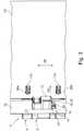
- Figure 3 shows the quick-assembly hinge 1 in a perspective view in an installation situation, the quick-assembly hinge 1 being fixed with the first hinge component 2 on a first mounting wall 22 and with the second hinge component 3 on a second mounting wall 23.
- the quick-assembly hinge 1 serves to form a hinge between the first and second assembly walls 22, 23, so that, for example, the first assembly wall 23 can be pivoted relative to the second assembly wall 22.
- the first and the second mounting wall 22, 23 are part of a sheet metal cabinet, for example a switch cabinet.
- the first mounting wall 22 forms a door frame and the second mounting wall 23 forms a door which can be pivoted relative to the door frame.
- the first mounting wall 22 has a first opening 24, the plug-in section 13 being inserted through the first opening 24 in an insertion direction SR and fixed in the first opening 24 by the snap device 14 .
- the first hinge component 2 with the contact section 9 rests on the rear of the first assembly wall 22 in the plug-in direction SR, and the first hinge component 2 is supported against the insertion direction SR via the first and the second inclined surface 19, 21.
- the first mounting wall 22 is thus arranged in a form-fitting manner between the first contact section 9 and the two inclined surfaces 19, 21.
- the opening 24 has a rectangular cross-sectional opening, the plug-in section 13 being positively received in the first opening 24 transversely to the plug-in direction SR.
- the second mounting wall 23 has a first and a second through opening 25a, b, the first threaded pin section 17a through the first through opening 25a and the second threaded pin section 17b through the second through opening 25b in the Insertion direction SR is performed.
- the second hinge component 3 rests on the rear of the second mounting wall 23 via the second contact section 11 in the plug-in direction SR, the second hinge component 3 being secured against the plug-in direction SR, for example, with a screw nut screwed onto the threaded pin sections 17a, b at the ends, not shown is.
- the second mounting wall 23 is thus arranged in a form-fitting manner between the second contact section 11 and the screw nuts.
- the two through-openings 25a, b are each designed as a through-bore, the two threaded pin sections 17a, b being received with an exact fit in the associated through-bore 25a, b.
- Figure 4 shows a sectional view through the first hinge component 2 in an installation situation with the first mounting wall 22.
- the snap member 15 has a retaining contour 26 designed as a snap hook, the plug-in section 13 having a receiving opening 27 which penetrates the plug-in section 13 in the direction of the guide channel 16, with the holding contour 26 engages behind the plug-in section 13 through the receiving opening 27.
- the plug-in section 13 has a guide slot 28, the holding contour 16 being displaceable in the guide slot 28 between a first and a second end stop 29a, b.
- the receiving opening 27 is made in the plug-in section 13 at the location of the first end stop 29a, the holding contour 29a at the location of the first end stop 29a being able to be elastically deformed by the receiving opening 27 so that the snap member 15 can be assembled or dismantled.
- the snap device 14 has a spring element 30 designed as a helical compression spring, which is arranged in the guide channel 16.
- the spring element 30 acts on the snap element 15 in a first displacement direction VR1 with a spring force so that the snap element 15 protrudes from the guide channel 16 with the end contour 18 and rests against the first end stop 29a via the holding contour 16.
- the spring element 30 is supported in the first displacement direction VR1 on the snap member 15 and in a second displacement direction VR2 directed opposite to the first displacement direction VR1 on the plug-in section 13.
- the plug-in section 13 has a pin aligned in the first displacement direction VR1 and to form a second spring seat 31b, the snap member 15 has a pin aligned in the second displacement direction VR2, with the spring element 30 being pushed onto the end of the two pins .
- the second inclined surface 24b is formed by a wedge-shaped molding of the plug-in section 13 in a transition area to the contact section 9.
- a second snap member can thus be dispensed with, so that the quick-assembly hinge 1 can be designed in a significantly simpler manner.
- the quick-assembly hinge 1 can be assembled in a particularly simple and cost-effective manner, with a particularly robust design of the quick-assembly hinge 1 being implemented by forming the second inclined surface 21 on the plug-in section.
- the plug-in section 13 When assembling the first hinge component 2, the plug-in section 13 is pushed in the plug-in direction SR through the opening 24, the snap member 15 with the sliding surface 20 sliding on an edge of the opening 24.
- the snap member 15 is moved in the second displacement direction VR2 into the guide channel 16 against the spring force.
- the plug-in section 13 is pushed into the opening until the first contact section 9 rests with its first contact surface 10 on the first mounting wall 22.
- the snap member 15 snaps out in the first displacement direction VR1, so that the Snap member 15 is supported with its first inclined surface 19 on a first edge 24a of opening 24.
- the plug-in section 13 is suspended in the second displacement direction VR2 between the first contact surface 10 and the second inclined surface 21, the second inclined surface 21 being supported on a second edge 24b opposite the first edge 24a.
- the plug-in section 13 is thus held in the opening 24 in a form-fitting and force-fitting manner.
- the snap element 15 must be pushed back in the second displacement direction VR2 so that the plug-in section 13 can be unhooked in the first displacement direction VR1 and removed from the opening 24 against the plug-in direction SR.
- Figures 5a, b each show the quick-assembly hinge 1 in a sectional view, wherein Figure 5a the quick-assembly hinge 1 in a longitudinal section along the pivot axis SA and Figure 5b represents the quick assembly hinge 1 in a cross section.
- the central section 5c of the hinge pin 5 has a latching receptacle 32 which serves to receive a latching member 33.
- the latching receptacle 32 is introduced laterally into the hinge pin 5, the latching member 33 being arranged within a receiving space 34 spatially connected to the guide section 6 and being displaceable relative to the latching receptacle 32 in the receiving space 34.
- the locking member 33 is acted upon by a spring device 35, which is formed by two compression springs, in the direction of the locking receptacle 32 with a spring force.
- the latching receptacle 32 is designed as a recess which is delimited in an axial direction and in an axially opposite direction with respect to the pivot axis SA by a respective inclined stop surface 36a, b.
- the hinge pin 5 is pushed through the through hole of the first receiving section 7 and then through the guide section 6 into the blind hole of the second receiving section 8. If the hinge pin 5 is fully inserted, the latching member 33 automatically engages in the Locking receptacle 32 so that the hinge pin 5 is secured against loss.
- the second end section 5b of the hinge pin 4 has a non-round contour, the second receiving section 5b having a corresponding mating contour so that the hinge pin 5 is secured against twisting.
- the contour of the second end section 5b is formed by a flattening.
- the hinge pin 4 is removed from the two receiving sections 7, 8 and the guide section 6, the locking member 33 sliding along the first contact surface 36a and being pushed back into the receiving space 34 against the spring force applied by the spring device 35.
- the hinge pin 5 is thus released and can be completely removed.
- the plug-in section 13 has a guide contour 37 for guiding the snap member 15 in the guide channel 16.
- the snap element 15 has a guide counter-contour 18, the guide contour 37 and the guide counter-contour 38 extending in the displacement direction VR and engaging with one another, so that the snap element 15 is guided in a straight line in the displacement direction VR.
- the guide contour 37 is formed by two mutually opposite webs which extend into the guide channel 16.
- the guide counter-contour 38 is formed by two grooves which are complementary to the two webs and which are introduced into the snap member 15 laterally opposite the associated web.
- the Figures 6a, b show an alternative embodiment of the quick-assembly hinge 1 as a further embodiment of the invention.
- the Figure 6a shows the quick-assembly hinge 1 in a perspective view, the second hinge component 3 having a further plug-in section 39 and a further snap-in device 40 instead of the two threaded pin sections 17a, b.
- the further plug-in section 39 and the further snap-in device 40 are constructed identically to the plug-in section 13 and the snap-in device 14 of the first hinge component 2, the two plug-in sections 13, 39 being aligned in opposite directions in the displacement direction VR.
- the Figure 6b shows the quick-assembly hinge 1 in an installation situation, the quick-assembly hinge 1 being fixed with the first hinge component 2 on the first mounting wall 22 and with the second hinge component 3 on the second mounting wall 23.
- the second mounting wall 22 has instead of the two through openings 25a, b, as in FIG Figure 3 shown, a second breakthrough 41.
- the quick-assembly hinge 1 is inserted in the plug-in direction SR with the first plug-in section 13 through the first opening 24 and with the second plug-in section 39 through the second opening 41 and fixed in the respective opening 24, 41 by the associated snap device 14, 40.
Landscapes
- Engineering & Computer Science (AREA)
- Mechanical Engineering (AREA)
- Hinges (AREA)
Applications Claiming Priority (1)
| Application Number | Priority Date | Filing Date | Title |
|---|---|---|---|
| DE202019103364.9U DE202019103364U1 (de) | 2019-06-14 | 2019-06-14 | Schnellmontagescharnier sowie Blechschrank mit dem Schnellmontagescharnier |
Publications (3)
| Publication Number | Publication Date |
|---|---|
| EP3751081A1 true EP3751081A1 (fr) | 2020-12-16 |
| EP3751081B1 EP3751081B1 (fr) | 2023-12-27 |
| EP3751081C0 EP3751081C0 (fr) | 2023-12-27 |
Family
ID=69148113
Family Applications (1)
| Application Number | Title | Priority Date | Filing Date |
|---|---|---|---|
| EP20179539.0A Active EP3751081B1 (fr) | 2019-06-14 | 2020-06-11 | Charnière de montage rapide ainsi qu'armoire en tôle dotée de la charnière de montage rapide |
Country Status (3)
| Country | Link |
|---|---|
| EP (1) | EP3751081B1 (fr) |
| DE (1) | DE202019103364U1 (fr) |
| PL (1) | PL3751081T3 (fr) |
Cited By (3)
| Publication number | Priority date | Publication date | Assignee | Title |
|---|---|---|---|---|
| CN113482478A (zh) * | 2021-09-07 | 2021-10-08 | 南通四维幕墙装饰装潢有限责任公司 | 一种铝合金门便于安装拆卸的装置 |
| CN118426281A (zh) * | 2024-07-04 | 2024-08-02 | 深圳辉业科技有限公司 | 一种组合型复印机金属铰链及复印机 |
| CN119754656A (zh) * | 2025-03-06 | 2025-04-04 | 台力电气有限公司 | 一种环网柜 |
Citations (2)
| Publication number | Priority date | Publication date | Assignee | Title |
|---|---|---|---|---|
| EP0992644A2 (fr) * | 1998-10-07 | 2000-04-12 | Dieter Ramsauer | Verrou à pêne pour le montage dans un paroi mince |
| DE202010006608U1 (de) | 2010-05-08 | 2011-11-08 | Dirak Dieter Ramsauer Konstruktionselemente Gmbh | Scharnier und mit derartigem Scharnier ausgestatteter Luftkanal, Wärmekanal, Kasten oder Schrank |
-
2019
- 2019-06-14 DE DE202019103364.9U patent/DE202019103364U1/de active Active
-
2020
- 2020-06-11 EP EP20179539.0A patent/EP3751081B1/fr active Active
- 2020-06-11 PL PL20179539.0T patent/PL3751081T3/pl unknown
Patent Citations (2)
| Publication number | Priority date | Publication date | Assignee | Title |
|---|---|---|---|---|
| EP0992644A2 (fr) * | 1998-10-07 | 2000-04-12 | Dieter Ramsauer | Verrou à pêne pour le montage dans un paroi mince |
| DE202010006608U1 (de) | 2010-05-08 | 2011-11-08 | Dirak Dieter Ramsauer Konstruktionselemente Gmbh | Scharnier und mit derartigem Scharnier ausgestatteter Luftkanal, Wärmekanal, Kasten oder Schrank |
Cited By (4)
| Publication number | Priority date | Publication date | Assignee | Title |
|---|---|---|---|---|
| CN113482478A (zh) * | 2021-09-07 | 2021-10-08 | 南通四维幕墙装饰装潢有限责任公司 | 一种铝合金门便于安装拆卸的装置 |
| CN113482478B (zh) * | 2021-09-07 | 2021-11-16 | 南通四维幕墙装饰装潢有限责任公司 | 一种铝合金门便于安装拆卸的装置 |
| CN118426281A (zh) * | 2024-07-04 | 2024-08-02 | 深圳辉业科技有限公司 | 一种组合型复印机金属铰链及复印机 |
| CN119754656A (zh) * | 2025-03-06 | 2025-04-04 | 台力电气有限公司 | 一种环网柜 |
Also Published As
| Publication number | Publication date |
|---|---|
| PL3751081T3 (pl) | 2024-05-13 |
| EP3751081B1 (fr) | 2023-12-27 |
| EP3751081C0 (fr) | 2023-12-27 |
| DE202019103364U1 (de) | 2019-12-17 |
Similar Documents
| Publication | Publication Date | Title |
|---|---|---|
| DE19646988C5 (de) | Beschlag für ein Fenster | |
| EP3556978B1 (fr) | Dispositif de déplacement d'une partie de meuble logée sur une partie d'un meuble | |
| EP2742199B1 (fr) | Système de fixation pour fixer une pièce sur une rainure d'une fenêtre, d'une porte ou analogue | |
| EP3751081B1 (fr) | Charnière de montage rapide ainsi qu'armoire en tôle dotée de la charnière de montage rapide | |
| WO2018033221A1 (fr) | Charnière de meuble | |
| EP3622153A1 (fr) | Commande de meuble à moteur | |
| DE202015100360U1 (de) | Kabelhalter und Kabelhaltersystem | |
| EP3535824B1 (fr) | Support de jeu de barres et ensemble correspondant | |
| DE202010007430U1 (de) | Vorrichtung mit einer Anbringeinrichtung und Schublade | |
| EP2754805B1 (fr) | Tringle de verrouillage pour une crémone | |
| EP2033266B1 (fr) | Borne de connexion de conducteur | |
| DE2702470B2 (de) | Feststellvorichtung für eine Tür, insbesondere an Kraftfahrzeugen | |
| DE102004023867B3 (de) | Befestigungselement für einen Betätigungszug bzw. eine Schlauchfassung eines Betätigungszuges | |
| WO2021110213A1 (fr) | Fermeture | |
| DE202016106504U1 (de) | Montagewerkzeug für die Montage einer Schaltschranktür an einem Schaltschrankgehäuse und eine entsprechende Schaltschrankanordnung | |
| EP1963604B1 (fr) | Pièce coulissante pour ferrure | |
| EP3303062B1 (fr) | Arrangement pour la fixation d'un element en forme de reglette | |
| DE102015120559B3 (de) | Montageelement zur Befestigung von Türbändern | |
| EP2754803A2 (fr) | Crémone de fenêtre ou de porte | |
| WO2023232182A1 (fr) | Agencement de barres de verrouillage | |
| EP1662627B1 (fr) | Dispositif pour la fixation détachable d'un boîtier d'appareil à un rail profilé | |
| DE102010028603B3 (de) | Beschlagteil zur Befestigung an einer C-förmigen Beschlagteilnut | |
| EP4232665A1 (fr) | Charnière de séparation | |
| EP4438839B1 (fr) | Unité de serrage pour la fixation d'une ferrure dans une rainure de ferrure d'une fenêtre ou d'une porte | |
| EP4286635B1 (fr) | Rail de coulissement pour un entraînement de porte |
Legal Events
| Date | Code | Title | Description |
|---|---|---|---|
| PUAI | Public reference made under article 153(3) epc to a published international application that has entered the european phase |
Free format text: ORIGINAL CODE: 0009012 |
|
| STAA | Information on the status of an ep patent application or granted ep patent |
Free format text: STATUS: THE APPLICATION HAS BEEN PUBLISHED |
|
| AK | Designated contracting states |
Kind code of ref document: A1 Designated state(s): AL AT BE BG CH CY CZ DE DK EE ES FI FR GB GR HR HU IE IS IT LI LT LU LV MC MK MT NL NO PL PT RO RS SE SI SK SM TR |
|
| AX | Request for extension of the european patent |
Extension state: BA ME |
|
| STAA | Information on the status of an ep patent application or granted ep patent |
Free format text: STATUS: REQUEST FOR EXAMINATION WAS MADE |
|
| 17P | Request for examination filed |
Effective date: 20210614 |
|
| RBV | Designated contracting states (corrected) |
Designated state(s): AL AT BE BG CH CY CZ DE DK EE ES FI FR GB GR HR HU IE IS IT LI LT LU LV MC MK MT NL NO PL PT RO RS SE SI SK SM TR |
|
| RIC1 | Information provided on ipc code assigned before grant |
Ipc: E05D 5/06 20060101ALN20230605BHEP Ipc: A47B 96/14 20060101ALI20230605BHEP Ipc: E05D 7/12 20060101ALI20230605BHEP Ipc: E05D 5/02 20060101ALI20230605BHEP Ipc: E05D 7/10 20060101AFI20230605BHEP |
|
| GRAP | Despatch of communication of intention to grant a patent |
Free format text: ORIGINAL CODE: EPIDOSNIGR1 |
|
| STAA | Information on the status of an ep patent application or granted ep patent |
Free format text: STATUS: GRANT OF PATENT IS INTENDED |
|
| INTG | Intention to grant announced |
Effective date: 20230721 |
|
| GRAS | Grant fee paid |
Free format text: ORIGINAL CODE: EPIDOSNIGR3 |
|
| GRAA | (expected) grant |
Free format text: ORIGINAL CODE: 0009210 |
|
| STAA | Information on the status of an ep patent application or granted ep patent |
Free format text: STATUS: THE PATENT HAS BEEN GRANTED |
|
| AK | Designated contracting states |
Kind code of ref document: B1 Designated state(s): AL AT BE BG CH CY CZ DE DK EE ES FI FR GB GR HR HU IE IS IT LI LT LU LV MC MK MT NL NO PL PT RO RS SE SI SK SM TR |
|
| REG | Reference to a national code |
Ref country code: GB Ref legal event code: FG4D Free format text: NOT ENGLISH |
|
| REG | Reference to a national code |
Ref country code: CH Ref legal event code: EP |
|
| REG | Reference to a national code |
Ref country code: DE Ref legal event code: R096 Ref document number: 502020006490 Country of ref document: DE |
|
| REG | Reference to a national code |
Ref country code: IE Ref legal event code: FG4D Free format text: LANGUAGE OF EP DOCUMENT: GERMAN |
|
| U01 | Request for unitary effect filed |
Effective date: 20231227 |
|
| U07 | Unitary effect registered |
Designated state(s): AT BE BG DE DK EE FI FR IT LT LU LV MT NL PT SE SI Effective date: 20240109 |
|
| PG25 | Lapsed in a contracting state [announced via postgrant information from national office to epo] |
Ref country code: GR Free format text: LAPSE BECAUSE OF FAILURE TO SUBMIT A TRANSLATION OF THE DESCRIPTION OR TO PAY THE FEE WITHIN THE PRESCRIBED TIME-LIMIT Effective date: 20240328 |
|
| PG25 | Lapsed in a contracting state [announced via postgrant information from national office to epo] |
Ref country code: ES Free format text: LAPSE BECAUSE OF FAILURE TO SUBMIT A TRANSLATION OF THE DESCRIPTION OR TO PAY THE FEE WITHIN THE PRESCRIBED TIME-LIMIT Effective date: 20231227 |
|
| PG25 | Lapsed in a contracting state [announced via postgrant information from national office to epo] |
Ref country code: GR Free format text: LAPSE BECAUSE OF FAILURE TO SUBMIT A TRANSLATION OF THE DESCRIPTION OR TO PAY THE FEE WITHIN THE PRESCRIBED TIME-LIMIT Effective date: 20240328 Ref country code: ES Free format text: LAPSE BECAUSE OF FAILURE TO SUBMIT A TRANSLATION OF THE DESCRIPTION OR TO PAY THE FEE WITHIN THE PRESCRIBED TIME-LIMIT Effective date: 20231227 |
|
| PG25 | Lapsed in a contracting state [announced via postgrant information from national office to epo] |
Ref country code: RS Free format text: LAPSE BECAUSE OF FAILURE TO SUBMIT A TRANSLATION OF THE DESCRIPTION OR TO PAY THE FEE WITHIN THE PRESCRIBED TIME-LIMIT Effective date: 20231227 Ref country code: NO Free format text: LAPSE BECAUSE OF FAILURE TO SUBMIT A TRANSLATION OF THE DESCRIPTION OR TO PAY THE FEE WITHIN THE PRESCRIBED TIME-LIMIT Effective date: 20240327 Ref country code: HR Free format text: LAPSE BECAUSE OF FAILURE TO SUBMIT A TRANSLATION OF THE DESCRIPTION OR TO PAY THE FEE WITHIN THE PRESCRIBED TIME-LIMIT Effective date: 20231227 |
|
| PG25 | Lapsed in a contracting state [announced via postgrant information from national office to epo] |
Ref country code: IS Free format text: LAPSE BECAUSE OF FAILURE TO SUBMIT A TRANSLATION OF THE DESCRIPTION OR TO PAY THE FEE WITHIN THE PRESCRIBED TIME-LIMIT Effective date: 20240427 |
|
| U20 | Renewal fee for the european patent with unitary effect paid |
Year of fee payment: 5 Effective date: 20240610 |
|
| PG25 | Lapsed in a contracting state [announced via postgrant information from national office to epo] |
Ref country code: CZ Free format text: LAPSE BECAUSE OF FAILURE TO SUBMIT A TRANSLATION OF THE DESCRIPTION OR TO PAY THE FEE WITHIN THE PRESCRIBED TIME-LIMIT Effective date: 20231227 |
|
| PG25 | Lapsed in a contracting state [announced via postgrant information from national office to epo] |
Ref country code: SK Free format text: LAPSE BECAUSE OF FAILURE TO SUBMIT A TRANSLATION OF THE DESCRIPTION OR TO PAY THE FEE WITHIN THE PRESCRIBED TIME-LIMIT Effective date: 20231227 |
|
| PG25 | Lapsed in a contracting state [announced via postgrant information from national office to epo] |
Ref country code: SM Free format text: LAPSE BECAUSE OF FAILURE TO SUBMIT A TRANSLATION OF THE DESCRIPTION OR TO PAY THE FEE WITHIN THE PRESCRIBED TIME-LIMIT Effective date: 20231227 Ref country code: SK Free format text: LAPSE BECAUSE OF FAILURE TO SUBMIT A TRANSLATION OF THE DESCRIPTION OR TO PAY THE FEE WITHIN THE PRESCRIBED TIME-LIMIT Effective date: 20231227 Ref country code: RO Free format text: LAPSE BECAUSE OF FAILURE TO SUBMIT A TRANSLATION OF THE DESCRIPTION OR TO PAY THE FEE WITHIN THE PRESCRIBED TIME-LIMIT Effective date: 20231227 Ref country code: IS Free format text: LAPSE BECAUSE OF FAILURE TO SUBMIT A TRANSLATION OF THE DESCRIPTION OR TO PAY THE FEE WITHIN THE PRESCRIBED TIME-LIMIT Effective date: 20240427 Ref country code: CZ Free format text: LAPSE BECAUSE OF FAILURE TO SUBMIT A TRANSLATION OF THE DESCRIPTION OR TO PAY THE FEE WITHIN THE PRESCRIBED TIME-LIMIT Effective date: 20231227 |
|
| REG | Reference to a national code |
Ref country code: DE Ref legal event code: R097 Ref document number: 502020006490 Country of ref document: DE |
|
| PLBE | No opposition filed within time limit |
Free format text: ORIGINAL CODE: 0009261 |
|
| STAA | Information on the status of an ep patent application or granted ep patent |
Free format text: STATUS: NO OPPOSITION FILED WITHIN TIME LIMIT |
|
| 26N | No opposition filed |
Effective date: 20240930 |
|
| PG25 | Lapsed in a contracting state [announced via postgrant information from national office to epo] |
Ref country code: MC Free format text: LAPSE BECAUSE OF FAILURE TO SUBMIT A TRANSLATION OF THE DESCRIPTION OR TO PAY THE FEE WITHIN THE PRESCRIBED TIME-LIMIT Effective date: 20231227 |
|
| REG | Reference to a national code |
Ref country code: CH Ref legal event code: PL |
|
| GBPC | Gb: european patent ceased through non-payment of renewal fee |
Effective date: 20240611 |
|
| PG25 | Lapsed in a contracting state [announced via postgrant information from national office to epo] |
Ref country code: IE Free format text: LAPSE BECAUSE OF NON-PAYMENT OF DUE FEES Effective date: 20240611 |
|
| PG25 | Lapsed in a contracting state [announced via postgrant information from national office to epo] |
Ref country code: CH Free format text: LAPSE BECAUSE OF NON-PAYMENT OF DUE FEES Effective date: 20240630 |
|
| PG25 | Lapsed in a contracting state [announced via postgrant information from national office to epo] |
Ref country code: GB Free format text: LAPSE BECAUSE OF NON-PAYMENT OF DUE FEES Effective date: 20240611 |
|
| PGFP | Annual fee paid to national office [announced via postgrant information from national office to epo] |
Ref country code: PL Payment date: 20250602 Year of fee payment: 6 |
|
| U20 | Renewal fee for the european patent with unitary effect paid |
Year of fee payment: 6 Effective date: 20250602 |
|
| PGFP | Annual fee paid to national office [announced via postgrant information from national office to epo] |
Ref country code: TR Payment date: 20250603 Year of fee payment: 6 |
|
| PG25 | Lapsed in a contracting state [announced via postgrant information from national office to epo] |
Ref country code: CY Free format text: LAPSE BECAUSE OF FAILURE TO SUBMIT A TRANSLATION OF THE DESCRIPTION OR TO PAY THE FEE WITHIN THE PRESCRIBED TIME-LIMIT; INVALID AB INITIO Effective date: 20200611 |
|
| PG25 | Lapsed in a contracting state [announced via postgrant information from national office to epo] |
Ref country code: HU Free format text: LAPSE BECAUSE OF FAILURE TO SUBMIT A TRANSLATION OF THE DESCRIPTION OR TO PAY THE FEE WITHIN THE PRESCRIBED TIME-LIMIT; INVALID AB INITIO Effective date: 20200611 |