EP3751173A1 - Dispositif de réglage pour un moteur à combustion interne - Google Patents
Dispositif de réglage pour un moteur à combustion interne Download PDFInfo
- Publication number
- EP3751173A1 EP3751173A1 EP20179664.6A EP20179664A EP3751173A1 EP 3751173 A1 EP3751173 A1 EP 3751173A1 EP 20179664 A EP20179664 A EP 20179664A EP 3751173 A1 EP3751173 A1 EP 3751173A1
- Authority
- EP
- European Patent Office
- Prior art keywords
- traction mechanism
- gear drive
- mechanism wheel
- wheel
- gear
- Prior art date
- Legal status (The legal status is an assumption and is not a legal conclusion. Google has not performed a legal analysis and makes no representation as to the accuracy of the status listed.)
- Pending
Links
Images




Classifications
-
- F—MECHANICAL ENGINEERING; LIGHTING; HEATING; WEAPONS; BLASTING
- F16—ENGINEERING ELEMENTS AND UNITS; GENERAL MEASURES FOR PRODUCING AND MAINTAINING EFFECTIVE FUNCTIONING OF MACHINES OR INSTALLATIONS; THERMAL INSULATION IN GENERAL
- F16H—GEARING
- F16H49/00—Other gearings
- F16H49/001—Wave gearings, e.g. harmonic drive transmissions
-
- F—MECHANICAL ENGINEERING; LIGHTING; HEATING; WEAPONS; BLASTING
- F01—MACHINES OR ENGINES IN GENERAL; ENGINE PLANTS IN GENERAL; STEAM ENGINES
- F01L—CYCLICALLY OPERATING VALVES FOR MACHINES OR ENGINES
- F01L1/00—Valve-gear or valve arrangements, e.g. lift-valve gear
- F01L1/34—Valve-gear or valve arrangements, e.g. lift-valve gear characterised by the provision of means for changing the timing of the valves without changing the duration of opening and without affecting the magnitude of the valve lift
- F01L1/344—Valve-gear or valve arrangements, e.g. lift-valve gear characterised by the provision of means for changing the timing of the valves without changing the duration of opening and without affecting the magnitude of the valve lift changing the angular relationship between crankshaft and camshaft, e.g. using helicoidal gear
- F01L1/352—Valve-gear or valve arrangements, e.g. lift-valve gear characterised by the provision of means for changing the timing of the valves without changing the duration of opening and without affecting the magnitude of the valve lift changing the angular relationship between crankshaft and camshaft, e.g. using helicoidal gear using bevel or epicyclic gear
-
- F—MECHANICAL ENGINEERING; LIGHTING; HEATING; WEAPONS; BLASTING
- F02—COMBUSTION ENGINES; HOT-GAS OR COMBUSTION-PRODUCT ENGINE PLANTS
- F02B—INTERNAL-COMBUSTION PISTON ENGINES; COMBUSTION ENGINES IN GENERAL
- F02B67/00—Engines characterised by the arrangement of auxiliary apparatus not being otherwise provided for, e.g. the apparatus having different functions; Driving auxiliary apparatus from engines, not otherwise provided for
- F02B67/04—Engines characterised by the arrangement of auxiliary apparatus not being otherwise provided for, e.g. the apparatus having different functions; Driving auxiliary apparatus from engines, not otherwise provided for of mechanically-driven auxiliary apparatus
- F02B67/06—Engines characterised by the arrangement of auxiliary apparatus not being otherwise provided for, e.g. the apparatus having different functions; Driving auxiliary apparatus from engines, not otherwise provided for of mechanically-driven auxiliary apparatus driven by means of chains, belts, or like endless members
-
- F—MECHANICAL ENGINEERING; LIGHTING; HEATING; WEAPONS; BLASTING
- F16—ENGINEERING ELEMENTS AND UNITS; GENERAL MEASURES FOR PRODUCING AND MAINTAINING EFFECTIVE FUNCTIONING OF MACHINES OR INSTALLATIONS; THERMAL INSULATION IN GENERAL
- F16H—GEARING
- F16H35/00—Gearings or mechanisms with other special functional features
- F16H35/008—Gearings or mechanisms with other special functional features for variation of rotational phase relationship, e.g. angular relationship between input and output shaft
-
- F—MECHANICAL ENGINEERING; LIGHTING; HEATING; WEAPONS; BLASTING
- F01—MACHINES OR ENGINES IN GENERAL; ENGINE PLANTS IN GENERAL; STEAM ENGINES
- F01L—CYCLICALLY OPERATING VALVES FOR MACHINES OR ENGINES
- F01L1/00—Valve-gear or valve arrangements, e.g. lift-valve gear
- F01L1/34—Valve-gear or valve arrangements, e.g. lift-valve gear characterised by the provision of means for changing the timing of the valves without changing the duration of opening and without affecting the magnitude of the valve lift
- F01L1/344—Valve-gear or valve arrangements, e.g. lift-valve gear characterised by the provision of means for changing the timing of the valves without changing the duration of opening and without affecting the magnitude of the valve lift changing the angular relationship between crankshaft and camshaft, e.g. using helicoidal gear
- F01L1/352—Valve-gear or valve arrangements, e.g. lift-valve gear characterised by the provision of means for changing the timing of the valves without changing the duration of opening and without affecting the magnitude of the valve lift changing the angular relationship between crankshaft and camshaft, e.g. using helicoidal gear using bevel or epicyclic gear
- F01L2001/3521—Harmonic drive of flexspline type
-
- F—MECHANICAL ENGINEERING; LIGHTING; HEATING; WEAPONS; BLASTING
- F01—MACHINES OR ENGINES IN GENERAL; ENGINE PLANTS IN GENERAL; STEAM ENGINES
- F01L—CYCLICALLY OPERATING VALVES FOR MACHINES OR ENGINES
- F01L2250/00—Camshaft drives characterised by their transmission means
- F01L2250/02—Camshaft drives characterised by their transmission means the camshaft being driven by chains
-
- F—MECHANICAL ENGINEERING; LIGHTING; HEATING; WEAPONS; BLASTING
- F01—MACHINES OR ENGINES IN GENERAL; ENGINE PLANTS IN GENERAL; STEAM ENGINES
- F01L—CYCLICALLY OPERATING VALVES FOR MACHINES OR ENGINES
- F01L2250/00—Camshaft drives characterised by their transmission means
- F01L2250/04—Camshaft drives characterised by their transmission means the camshaft being driven by belts
-
- F—MECHANICAL ENGINEERING; LIGHTING; HEATING; WEAPONS; BLASTING
- F01—MACHINES OR ENGINES IN GENERAL; ENGINE PLANTS IN GENERAL; STEAM ENGINES
- F01L—CYCLICALLY OPERATING VALVES FOR MACHINES OR ENGINES
- F01L2250/00—Camshaft drives characterised by their transmission means
- F01L2250/06—Camshaft drives characterised by their transmission means the camshaft being driven by gear wheels
-
- F—MECHANICAL ENGINEERING; LIGHTING; HEATING; WEAPONS; BLASTING
- F01—MACHINES OR ENGINES IN GENERAL; ENGINE PLANTS IN GENERAL; STEAM ENGINES
- F01L—CYCLICALLY OPERATING VALVES FOR MACHINES OR ENGINES
- F01L2820/00—Details on specific features characterising valve gear arrangements
- F01L2820/03—Auxiliary actuators
- F01L2820/032—Electric motors
-
- F—MECHANICAL ENGINEERING; LIGHTING; HEATING; WEAPONS; BLASTING
- F16—ENGINEERING ELEMENTS AND UNITS; GENERAL MEASURES FOR PRODUCING AND MAINTAINING EFFECTIVE FUNCTIONING OF MACHINES OR INSTALLATIONS; THERMAL INSULATION IN GENERAL
- F16H—GEARING
- F16H1/00—Toothed gearings for conveying rotary motion
- F16H1/28—Toothed gearings for conveying rotary motion with gears having orbital motion
- F16H1/32—Toothed gearings for conveying rotary motion with gears having orbital motion in which the central axis of the gearing lies inside the periphery of an orbital gear
-
- F—MECHANICAL ENGINEERING; LIGHTING; HEATING; WEAPONS; BLASTING
- F16—ENGINEERING ELEMENTS AND UNITS; GENERAL MEASURES FOR PRODUCING AND MAINTAINING EFFECTIVE FUNCTIONING OF MACHINES OR INSTALLATIONS; THERMAL INSULATION IN GENERAL
- F16H—GEARING
- F16H1/00—Toothed gearings for conveying rotary motion
- F16H1/28—Toothed gearings for conveying rotary motion with gears having orbital motion
- F16H1/32—Toothed gearings for conveying rotary motion with gears having orbital motion in which the central axis of the gearing lies inside the periphery of an orbital gear
- F16H2001/323—Toothed gearings for conveying rotary motion with gears having orbital motion in which the central axis of the gearing lies inside the periphery of an orbital gear comprising eccentric crankshafts driving or driven by a gearing
Definitions
- the invention relates to a method for producing an adjusting device for an internal combustion engine, which has a traction mechanism wheel and a three-shaft transmission with a first gear drive, a second gear drive and a gear output.
- the invention also relates to an adjustment device for an internal combustion engine, which has a traction mechanism wheel and a three-shaft transmission with a first transmission drive, a second transmission drive and a transmission output.
- the invention also relates to a camshaft adjuster.
- the invention also relates to a device for setting the expansion stroke and / or the compression ratio of an internal combustion engine with such an adjusting device.
- a harmonic drive is known with at least one ring gear with internal toothing, a flexible spur gear arranged inside the ring gear with external toothing and a wave generator arranged inside the spur gear for bending the spur gear in the radial direction.
- a torque-transmitting connection is established between the ring gear and the spur gear at two opposite points on the spur gear, the wave generator comprising a ring with an elliptical outer circumference and an elliptically deformed bearing mounted on the outer circumference.
- the spur gear is axially supported on both sides by a cover.
- Out DE 20 2015 009 214 U1 is a harmonic drive with a wave generator, a flexible, externally toothed gear component that can be deformed by this, as well as at least one internally toothed gear that meshes with the flexible, externally toothed gear component Transmission component known.
- the flexible, externally toothed transmission component has a non-round basic shape in relation to its mechanically unloaded state.
- the harmonic drive can be designed as an adjusting gear of an electric camshaft adjuster.
- an adjusting device in particular for adjusting a camshaft, comprising a drive shaft, an output shaft and a harmonic drive connected between the drive shaft and the output shaft with a wave generator, an elastically deformable element and a ring gear is known.
- An element-side external toothing is in engagement with an internal toothing on the ring gear side, the elastically deformable element being mounted in a rotationally fixed manner and the ring gear being coupled in terms of movement to the output shaft.
- the adjustment device is used in particular to adjust a camshaft of an internal combustion engine of a motor vehicle.
- a camshaft adjuster which includes a tension wave transmission.
- the voltage wave transmission has at least two inputs and one output, the movement of which results from the superimposition of the movements of the inputs, one of the inputs being designed to carry out a main movement and the other input being used to carry out an adjustment movement which sets the phase position of the output relative to the phase position of the input performing the main movement is adjusted.
- a camshaft adjuster for varying the phase relationship between a crankshaft and a camshaft in an internal combustion engine which has a harmonic drive transmission unit with a circular spline and a dynamic spline, a flexspline which is arranged in the circular spline and the dynamic spline, a Wave generator which is arranged in the Flexspline has.
- the camshaft adjuster also has a Rotary actuator that is connected to the shaft generator.
- Out DE 10 2011 116 952 A1 is a multi-joint crankshaft drive of an internal combustion engine, with a plurality of coupling links rotatably mounted on crank pins of a crankshaft and a plurality of coupling rods rotatably mounted on crank pins of an eccentric shaft, each of the coupling members pivotably connected to a piston connecting rod of a piston of the internal combustion engine and one of the connecting rods and the angular position of the Eccentric shaft is adjustable by means of an adjusting device within a certain angle of rotation range, known.
- a device for variably setting the compression which has a multi-joint crank drive and in which an adjusting device for adjusting the angle of rotation of an eccentric shaft comprises a lever arrangement.
- the eccentric shaft can be rotated via the lever arrangement and thus a desired angle of rotation can be set.
- Another object of the present invention is to specify an adjusting device for an internal combustion engine that can be used with different internal combustion engines.
- the invention is based on the idea of always using the same adjusting device despite the mostly very different requirements of different internal combustion engines with regard to the geometry and the structural space conditions for the coupling of an adjusting device. It was recognized according to the invention that it is particularly advantageous to provide flexibility with regard to the axial position of the traction mechanism wheel. This advantageously means that the adjusting device according to the invention can be designed individually with little effort for use with very different internal combustion engines, for example as a camshaft adjuster or as a device for setting the expansion stroke and / or the compression ratio of an internal combustion engine.
- the adjusting device has a three-shaft transmission with a first transmission drive, a second transmission drive and a transmission output.
- the first gear drive is designed to be operatively coupled to the crankshaft of an internal combustion engine, for example via a traction mechanism, while the second gear drive is operatively coupled to an electric drive motor and the gear output is operatively coupled to the camshaft.
- the control times of the valve control of an internal combustion engine can be set or adjusted by a suitable control of the drive motor.
- the adjusting device can be designed to drive an adjusting shaft for adjusting the expansion stroke and / or the compression ratio of an internal combustion engine.
- the first gear drive is operatively coupled to the crankshaft of an internal combustion engine, for example via a traction mechanism, while the second gear drive with an electric drive motor and the gear output with an adjusting shaft, in particular an eccentric shaft, for adjusting the expansion stroke and / or the compression ratio of an internal combustion engine.
- the three-shaft transmission can advantageously be designed as a stress-shaft transmission, which is explained in detail below.
- the three-shaft transmission can also be designed, for example, as a planetary transmission or as a cycloid transmission.
- the adjusting device has a traction mechanism wheel, which can in particular be designed as part of a traction mechanism.
- the traction mechanism wheel can be designed and intended to be operatively connected to the crankshaft of an internal combustion engine via a traction mechanism.
- the traction mechanism wheel is designed as a chain wheel.
- a coupling to the crankshaft of an internal combustion engine is made possible by means of a control chain.
- the traction mechanism wheel can in particular also be designed as a double chain wheel for the use of a duplex chain.
- the traction mechanism wheel is designed as a belt wheel for the use of a toothed belt.
- the above-mentioned flexibility with regard to the axial traction mechanism wheel position can be achieved by different measures, whereby it is also possible to use several of the measures in combination.
- the decisive factor for the axial position of the traction mechanism wheel is ultimately the axial plane in which the traction mechanism coupled to the traction mechanism wheel runs after complete assembly.
- the first gear drive has at least two axially spaced coupling receptacles
- flexibility with regard to the axial traction mechanism wheel position is created in that the traction mechanism wheel can be optionally attached in different coupling receptacles.
- the traction mechanism wheel can be designed asymmetrically, so that a different axial traction mechanism wheel position can be achieved depending on its installation orientation, with the plane in which the traction mechanism ultimately runs is decisive for the traction mechanism wheel position, as already mentioned.
- the traction mechanism wheel can be designed as an externally toothed disk which has a collar on one side and which is axially attached to the first gear drive becomes. Depending on whether the traction mechanism wheel is attached to the first gear drive with the collar side or with the collar-free side, a different axial traction mechanism wheel position results.
- the asymmetry of the traction mechanism wheel can in particular be implemented in that the traction mechanism wheel is not designed to be mirror-symmetrical with respect to the plane in which the traction mechanism runs after complete assembly and / or that the traction mechanism wheel with regard to a rotation, in particular with regard to a rotation through 180 degrees, is not rotationally symmetrical about an axis perpendicular to the axial direction.
- an asymmetrically designed traction mechanism wheel is also possible in particular in combination with a first gear drive which has at least two coupling receptacles which are axially spaced from one another. This achieves a particularly high level of flexibility with regard to the possible axial traction mechanism wheel positions. In particular, there can even be several different traction mechanism wheels, one of which can be selected for assembly, which further increases flexibility.
- the first gear drive has only a single coupling receptacle, but at least two different traction mechanism wheels and / or at least one asymmetrical traction mechanism wheel are available for realizing one of at least two different possible axial traction mechanism wheel positions.
- a further traction mechanism wheel that is different from the traction mechanism wheel, with either the traction mechanism wheel or the further traction mechanism wheel being rotatably connectable or being connected to the first gear drive in order to implement one of at least two different possible axial traction mechanism wheel positions.
- the traction mechanism wheel and the further traction mechanism wheel can differ, for example, with regard to their shape and / or size and / or their diameter and / or their number of teeth and / or their axial length and / or their symmetry properties.
- traction mechanism wheels can advantageously be implemented in particular in combination with a first gear drive which has at least two axially spaced coupling receptacles, whereby a particularly high flexibility with regard to the axial traction mechanism wheel position is achieved.
- traction mechanism wheels as described above, to be designed asymmetrically in order to achieve even greater flexibility with regard to the possible axial traction mechanism wheel positions.
- the traction mechanism wheel (or, after a corresponding selection, the further traction mechanism wheel) can be attached to the first gear drive in a rotationally fixed manner in various ways.
- the traction mechanism wheel can be connected non-rotatably to the first gear drive, for example by means of at least one screw connection.
- the traction mechanism wheel is non-rotatably connected to the first gear drive by means of at least one form-fit connection, in particular by means of a plug connection, and / or that the traction mechanism wheel is rotatably connected to the first gear drive by means of at least one material connection, for example by welding, soldering or gluing first gear drive is connected.
- the traction mechanism wheel is non-rotatably connected to the first gear drive by means of a frictional connection.
- the first transmission output has at least one flange on which the traction mechanism wheel is fixed.
- the flange can have threaded bores into which fastening screws can be screwed.
- the threaded bores can in particular be arranged axially aligned on a bolt circle.
- Preferably has one such Execution of the traction mechanism wheel on matching through holes on an identical bolt circle.
- the traction mechanism wheel has threaded bores, while the flange has through bores, passed through the fastening screws and then screwed into the threaded bores in order to fix the traction mechanism wheel.
- the three-shaft transmission can advantageously be designed as a stress-shaft transmission.
- the stress wave gear can in particular be designed as a ring gear.
- a ring gear has a dynamic spline and a circular spline.
- the Dynamic Spline and the Circular Spline can be designed as internally toothed ring gears that mesh with an externally toothed Flexspline.
- the circular spline forms the first gear drive
- the dynamic spline forms the gear output, or vice versa.
- a shaft generator in particular an elliptical shaft generator, which forms the second gear drive, can be rotatably mounted radially within the flexspline.
- the output shaft of an, in particular electric, drive motor can be coupled to the second gear drive.
- the wave generator is mounted in a floating manner in the axial and / or radial direction.
- the output shaft of a drive motor in particular an electric drive motor, is mounted floatingly in the axial and / or radial direction within the shaft generator.
- an Oldham coupling is arranged in the drive train between a drive motor, which drives the shaft generator to rotate, and the shaft generator.
- the stress wave gear can also be designed as a pot gear, for example.
- the circular spline is designed as an internally toothed ring gear and forms the first gear drive, while the cup-shaped flexspline forms the gear output or is non-rotatably connected to an output shaft forming the output.
- an internal combustion engine that has an adjustment device according to the invention is particularly advantageous.
- the adjusting device is used as a camshaft adjuster for setting or adjusting the control times.
- the adjusting device is used to drive an adjusting shaft for adjusting the expansion stroke and / or the compression ratio of the internal combustion engine.
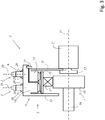
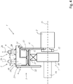
- the Figures 1 and 2 show a first exemplary embodiment of an adjusting device 1 according to the invention.
- the adjusting device 1 is coupled to a camshaft 2 of an internal combustion engine (not shown further).
- the adjusting device 1 has a traction mechanism wheel 3, which is designed as a chain wheel 4.
- the adjusting device 1 also has a three-shaft gear 5.
- the traction mechanism wheel 3 is non-rotatably connected to a first gear drive 6 of the three-shaft gear 5.
- the three-shaft gear 5 has a second gear drive 7 which is coupled to an electric drive motor 8.
- the three-shaft transmission 5 also has a transmission output 11 which is coupled to the camshaft 2 in a torque-proof manner.
- the adjusting device 1 is designed to be rotationally symmetrical with respect to the axial center axis 27.
- the first gear drive 6 has two coupling receptacles 9, 10 axially spaced from one another, namely a first coupling receptacle 9 and a second coupling receptacle 10.
- the traction wheel 3 can optionally in the first coupling receptacle 9 rotatably connected to the first gear drive 6, which is shown in Figure 1 is shown, or in the second coupling receptacle 10, which is shown in FIG Figure 2 is shown.
- the axial plane 28, 29 is decisive for the axial position of the traction mechanism wheel, in which the traction mechanism coupled to the traction mechanism wheel 3 (not shown) runs after complete assembly. If the Buchrad 3 is arranged in the first Ankoppelfact 9, the axial Werganradposition is in a first axial plane 28. If the Buchrad 3 is arranged in the second Ankoppelfact 10, the axial Werganradposition is in a second axial plane 29, which is from the first axial plane 28 is axially spaced.
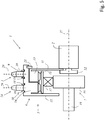
- Figure 3 shows a second embodiment of an adjusting device 1 according to the invention, with some rotationally symmetrical components only shown in half.
- the adjusting device 1 is designed to be rotationally symmetrical with respect to the axial center axis 27.
- the three-shaft gear 5 is designed as a stress-wave gear in the form of a ring gear.
- the transmission output 11 of the three-shaft transmission 5 is non-rotatably connected to a camshaft 2 of an internal combustion engine (not shown) by means of a fastening screw 12.
- the stress wave transmission has a dynamic spline 13 and a circular spline 14.
- the dynamic spline 13 and the circular spline 14 are designed as internally toothed ring gears, which mesh with an externally toothed flexspline 15.
- the circular spline 14 forms the first gear drive 6, while the dynamic spline is non-rotatably connected to the gear output 11.
- Radially within the flexspline 15 is an elliptical wave generator 16 by means of a radially flexible bearing 17 rotatably mounted, which forms the second gear drive 18.
- the output shaft 19 of an electric drive motor (not shown in detail) is coupled to the second gear drive 7.
- the first gear drive 6 has two coupling receptacles 9, 10 which are axially spaced apart from one another, namely a first coupling receptacle 9 and a second coupling receptacle 10.
- the traction mechanism wheel 3 can be connected to the first gear drive 6 in a rotationally fixed manner, for example by means of welded connections 20, in the first coupling receptacle 9, which is shown in the figure with solid lines, or in the second coupling receptacle 10, which is shown in the figure with dashed lines.
- the axial Switzerlandffenradposition is in a first axial plane 28. If the Buchrad 3 is arranged in the second Ankoppelage 10, the axial Werganradposition is in a second axial plane 29, which is from the first axial plane 28 is axially spaced.
- a securing ring 21 inserted into a circumferential groove of the circular spline 14 is provided.
- the circular spline 14 is designed in one piece with a wall 22 which, together with the transmission output 11, forms an axial securing device for the flexspline 15.
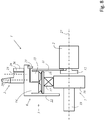
- Figure 4 shows a third embodiment of an adjusting device 1 according to the invention.
- the third embodiment differs from the second embodiment in that the wall 22 is not formed in one piece with the circular spline 14, but is screwed to it by means of a fastening screw 23.
- fastening by material connection would also be possible and / or frictional engagement possible.
- a connection by riveting, welding or with the aid of retaining rings is also possible, for example.
- Figure 5 shows a fourth embodiment of an adjustment device 1 according to the invention.
- the fourth embodiment differs from the second embodiment in that the traction mechanism wheel 3 is not connected to the first gear drive 6 by means of welded connections. Rather, it is provided that the traction mechanism wheel 3 is held in a rotationally fixed manner by means of a form-fit connection.
- the traction mechanism wheel 3 can have internal toothing (not shown), for example, which engages in a correspondingly complementary external toothing of the first gear drive 6.
- retaining rings 18 are embedded in circumferential grooves.
- Figure 6 shows a fifth exemplary embodiment of an adjusting device 1 according to the invention.
- the fifth exemplary embodiment differs from the fourth exemplary embodiment in that a further traction mechanism wheel 24 is present, which is different from the traction mechanism wheel 3.
- the further traction mechanism wheel 24 has a different diameter than the traction mechanism wheel 3.
- the further traction mechanism wheel 24 can be arranged instead of the traction mechanism wheel 3 in one of the coupling receptacles 9, 10 which are axially spaced apart from one another.
- the first gear drive 6 could only have a single coupling receptacle 9, but flexibility with regard to the axial traction mechanism wheel position is provided by the optional use of either the traction mechanism wheel 23 or the further traction mechanism wheel 24.
- the Figures 7 and 8th show a sixth embodiment of a Adjusting device according to the invention 1.
- the traction mechanism wheel 3 is designed asymmetrically and, in order to implement one of at least two different possible axial traction mechanism wheel positions, can be optionally with a first orientation (shown in FIG Figure 7 ) relative to the first gear drive 6 or with a second orientation different from the first orientation (shown in FIG Figure 8 ) be connected to the first gear drive 6 in a rotationally fixed manner relative to the first gear drive 6.
- the axial traction mechanism wheel position is in a first axial plane 28. If the traction mechanism wheel 3 is in the second orientation (shown in FIG Figure 8 ) is non-rotatably connected to the first gear drive 6 relative to the first gear drive 6 relative to the first gear drive 6, the axial Werganradposition is in a second axial plane 29, which is axially spaced from the first axial plane 28.
- the traction mechanism wheel 3 is designed as an externally toothed disk which has a collar 25 on one side and which is fastened axially against a radially protruding stop 26 of the first gear drive 6. Depending on whether the traction mechanism wheel is fastened with the collar side or with the collar-free side in contact with the stop 26, a different axial traction mechanism wheel position results.
- a material connection for example by welding or soldering
- a form-fitting connection for example by screws, rivets or a plug connection
- a Frictional connection for example by a press fit
Landscapes
- Engineering & Computer Science (AREA)
- General Engineering & Computer Science (AREA)
- Mechanical Engineering (AREA)
- Chemical & Material Sciences (AREA)
- Combustion & Propulsion (AREA)
- Valve Device For Special Equipments (AREA)
Applications Claiming Priority (1)
| Application Number | Priority Date | Filing Date | Title |
|---|---|---|---|
| LU101266 | 2019-06-12 |
Publications (1)
| Publication Number | Publication Date |
|---|---|
| EP3751173A1 true EP3751173A1 (fr) | 2020-12-16 |
Family
ID=67470590
Family Applications (1)
| Application Number | Title | Priority Date | Filing Date |
|---|---|---|---|
| EP20179664.6A Pending EP3751173A1 (fr) | 2019-06-12 | 2020-06-12 | Dispositif de réglage pour un moteur à combustion interne |
Country Status (1)
| Country | Link |
|---|---|
| EP (1) | EP3751173A1 (fr) |
Citations (9)
| Publication number | Priority date | Publication date | Assignee | Title |
|---|---|---|---|---|
| EP1715143A2 (fr) * | 2005-04-23 | 2006-10-25 | Schaeffler KG | Déphaseur d'arbre à cames de moteur à combustion interne |
| EP2022959A2 (fr) | 2007-08-10 | 2009-02-11 | Nissan Motor Company Limited | Dispositif de taux de compression variable pour moteur à combustion interne |
| EP2282020A1 (fr) * | 2009-08-06 | 2011-02-09 | Delphi Technologies, Inc. | Déphaseur d'arbre à cames à commande harmonique avec ressort de rappel |
| DE102010006392B3 (de) | 2010-02-01 | 2011-05-12 | Ovalo Gmbh | Spannungswellengetriebe und Nockenwellenversteller mit Spannungswellengetriebe |
| DE102011004075A1 (de) | 2011-02-14 | 2012-08-16 | Schaeffler Technologies Gmbh & Co. Kg | Wellgetriebe mit seitlicher Führung des Stirnrades |
| DE102011116952A1 (de) | 2011-10-26 | 2013-05-02 | Audi Ag | Mehrgelenkskurbeltrieb einer Brennkraftmaschine sowie Verfahren zum Betreiben eines Mehrgelenkskurbeltriebs |
| DE102013216183A1 (de) | 2013-08-14 | 2015-02-19 | Schaeffler Technologies Gmbh & Co. Kg | Verstelleinrichtung |
| DE202015009214U1 (de) | 2015-12-01 | 2016-11-29 | Schaeffler Technologies AG & Co. KG | Wellgetriebe |
| DE102015223904B3 (de) * | 2015-12-01 | 2017-03-02 | Schaeffler Technologies AG & Co. KG | Wellgetriebe |
-
2020
- 2020-06-12 EP EP20179664.6A patent/EP3751173A1/fr active Pending
Patent Citations (10)
| Publication number | Priority date | Publication date | Assignee | Title |
|---|---|---|---|---|
| EP1715143A2 (fr) * | 2005-04-23 | 2006-10-25 | Schaeffler KG | Déphaseur d'arbre à cames de moteur à combustion interne |
| EP2022959A2 (fr) | 2007-08-10 | 2009-02-11 | Nissan Motor Company Limited | Dispositif de taux de compression variable pour moteur à combustion interne |
| EP2282020A1 (fr) * | 2009-08-06 | 2011-02-09 | Delphi Technologies, Inc. | Déphaseur d'arbre à cames à commande harmonique avec ressort de rappel |
| EP2282020B1 (fr) | 2009-08-06 | 2013-05-15 | Delphi Technologies, Inc. | Déphaseur d'arbre à cames à commande harmonique avec ressort de rappel |
| DE102010006392B3 (de) | 2010-02-01 | 2011-05-12 | Ovalo Gmbh | Spannungswellengetriebe und Nockenwellenversteller mit Spannungswellengetriebe |
| DE102011004075A1 (de) | 2011-02-14 | 2012-08-16 | Schaeffler Technologies Gmbh & Co. Kg | Wellgetriebe mit seitlicher Führung des Stirnrades |
| DE102011116952A1 (de) | 2011-10-26 | 2013-05-02 | Audi Ag | Mehrgelenkskurbeltrieb einer Brennkraftmaschine sowie Verfahren zum Betreiben eines Mehrgelenkskurbeltriebs |
| DE102013216183A1 (de) | 2013-08-14 | 2015-02-19 | Schaeffler Technologies Gmbh & Co. Kg | Verstelleinrichtung |
| DE202015009214U1 (de) | 2015-12-01 | 2016-11-29 | Schaeffler Technologies AG & Co. KG | Wellgetriebe |
| DE102015223904B3 (de) * | 2015-12-01 | 2017-03-02 | Schaeffler Technologies AG & Co. KG | Wellgetriebe |
Similar Documents
| Publication | Publication Date | Title |
|---|---|---|
| DE102014202060B4 (de) | Nockenwellenversteller und Verfahren zum Betrieb eines Nockenwellenverstellers | |
| DE102016217055B4 (de) | Getriebe mit elastischem Zahnrad | |
| WO2003027538A1 (fr) | Transmission | |
| DE102014112689A9 (de) | Koaxialgetriebe und Anordnung zum Antreiben einer Verstellwelle zum Verstellen des Expansionshubes und/oder des Verdichtungsverhältnisses eines Verbrennungsmotors | |
| WO2017041800A1 (fr) | Transmission à roue dentée élastique | |
| DE102016219919A1 (de) | Elastisches Zahnrad eines Wellgetriebes | |
| WO2018095464A1 (fr) | Dispositif mécanisme de réglage pour un arbre ainsi que véhicule comprenant le dispositif mécanisme de réglage | |
| DE102004008538B4 (de) | Differential mit einer Bolzenbefestigungsbaugruppe | |
| EP1902224A1 (fr) | Assemblage arbre-moyeu ayant un cone reel | |
| WO2020020403A1 (fr) | Réducteur harmonique | |
| DE102008046821B4 (de) | Kurbelwelle für eine Brennkraftmaschine mit varibaler Verdichtung und Brennkraftmaschine mit variabler Verdichtung | |
| EP2616644A1 (fr) | Dispositif de déphasage de l'angle de rotation d'un pignon d'entrée par rapport à un pignon de sortie | |
| DE102016210865A1 (de) | Stellvorrichtung | |
| WO2021151591A1 (fr) | Fixation d'une denture à ajustement serré | |
| EP3765769B1 (fr) | Engrenage à roues dentées | |
| EP3751173A1 (fr) | Dispositif de réglage pour un moteur à combustion interne | |
| DE102018113091A1 (de) | Verstellvorrichtung, insbesondere Nockenwellenversteller | |
| EP3578769B1 (fr) | Dispositif de réglage, en particulier régulateur d'arbre à cames | |
| DE102021213313B4 (de) | Welle-Nabe-Verbindung | |
| WO2020011304A1 (fr) | Réducteur elliptique | |
| DE102020129738B4 (de) | Wellgetriebe, Verfahren zur Herstellung eines Wellgetriebes und Brennkraftmaschine mit Wellgetriebe aufweisenden Nockenwellenverstellern | |
| DE102019115926A1 (de) | Verstellvorrichtung für einen Verbrennungsmotor | |
| DE102016214917A1 (de) | Stirnradbüchseneinrichtung für ein Wellgetriebe sowie Wellenverstellanordnung mit dem Wellgetriebe | |
| EP3532711B1 (fr) | Ensemble mécanisme de réglage pour un véhicule, véhicule comprenant l'ensemble mécanisme de réglage ainsi que procédé de montage de l'ensemble mécanisme de réglage | |
| DE102017112032A1 (de) | Dreiwellengetriebe |
Legal Events
| Date | Code | Title | Description |
|---|---|---|---|
| PUAI | Public reference made under article 153(3) epc to a published international application that has entered the european phase |
Free format text: ORIGINAL CODE: 0009012 |
|
| STAA | Information on the status of an ep patent application or granted ep patent |
Free format text: STATUS: THE APPLICATION HAS BEEN PUBLISHED |
|
| AK | Designated contracting states |
Kind code of ref document: A1 Designated state(s): AL AT BE BG CH CY CZ DE DK EE ES FI FR GB GR HR HU IE IS IT LI LT LU LV MC MK MT NL NO PL PT RO RS SE SI SK SM TR |
|
| AX | Request for extension of the european patent |
Extension state: BA ME |
|
| STAA | Information on the status of an ep patent application or granted ep patent |
Free format text: STATUS: REQUEST FOR EXAMINATION WAS MADE |
|
| 17P | Request for examination filed |
Effective date: 20210615 |
|
| RBV | Designated contracting states (corrected) |
Designated state(s): AL AT BE BG CH CY CZ DE DK EE ES FI FR GB GR HR HU IE IS IT LI LT LU LV MC MK MT NL NO PL PT RO RS SE SI SK SM TR |
|
| STAA | Information on the status of an ep patent application or granted ep patent |
Free format text: STATUS: THE APPLICATION IS DEEMED TO BE WITHDRAWN |