EP3752982B1 - Intraorale abtastung mit oberflächendifferenzierung - Google Patents
Intraorale abtastung mit oberflächendifferenzierung Download PDFInfo
- Publication number
- EP3752982B1 EP3752982B1 EP19704779.8A EP19704779A EP3752982B1 EP 3752982 B1 EP3752982 B1 EP 3752982B1 EP 19704779 A EP19704779 A EP 19704779A EP 3752982 B1 EP3752982 B1 EP 3752982B1
- Authority
- EP
- European Patent Office
- Prior art keywords
- scanner
- views
- data
- intraoral
- machine learning
- Prior art date
- Legal status (The legal status is an assumption and is not a legal conclusion. Google has not performed a legal analysis and makes no representation as to the accuracy of the status listed.)
- Active
Links
Images



Classifications
-
- G—PHYSICS
- G06—COMPUTING OR CALCULATING; COUNTING
- G06T—IMAGE DATA PROCESSING OR GENERATION, IN GENERAL
- G06T7/00—Image analysis
- G06T7/50—Depth or shape recovery
- G06T7/55—Depth or shape recovery from multiple images
-
- A—HUMAN NECESSITIES
- A61—MEDICAL OR VETERINARY SCIENCE; HYGIENE
- A61C—DENTISTRY; APPARATUS OR METHODS FOR ORAL OR DENTAL HYGIENE
- A61C9/00—Impression cups, i.e. impression trays; Impression methods
- A61C9/004—Means or methods for taking digitized impressions
- A61C9/0046—Data acquisition means or methods
- A61C9/0053—Optical means or methods, e.g. scanning the teeth by a laser or light beam
- A61C9/0073—Interferometric means or methods, e.g. creation of a hologram
-
- A—HUMAN NECESSITIES
- A61—MEDICAL OR VETERINARY SCIENCE; HYGIENE
- A61C—DENTISTRY; APPARATUS OR METHODS FOR ORAL OR DENTAL HYGIENE
- A61C9/00—Impression cups, i.e. impression trays; Impression methods
- A61C9/004—Means or methods for taking digitized impressions
- A61C9/0046—Data acquisition means or methods
- A61C9/0053—Optical means or methods, e.g. scanning the teeth by a laser or light beam
- A61C9/0066—Depth determination through adaptive focusing
-
- G—PHYSICS
- G03—PHOTOGRAPHY; CINEMATOGRAPHY; ANALOGOUS TECHNIQUES USING WAVES OTHER THAN OPTICAL WAVES; ELECTROGRAPHY; HOLOGRAPHY
- G03B—APPARATUS OR ARRANGEMENTS FOR TAKING PHOTOGRAPHS OR FOR PROJECTING OR VIEWING THEM; APPARATUS OR ARRANGEMENTS EMPLOYING ANALOGOUS TECHNIQUES USING WAVES OTHER THAN OPTICAL WAVES; ACCESSORIES THEREFOR
- G03B35/00—Stereoscopic photography
- G03B35/02—Stereoscopic photography by sequential recording
-
- G—PHYSICS
- G03—PHOTOGRAPHY; CINEMATOGRAPHY; ANALOGOUS TECHNIQUES USING WAVES OTHER THAN OPTICAL WAVES; ELECTROGRAPHY; HOLOGRAPHY
- G03B—APPARATUS OR ARRANGEMENTS FOR TAKING PHOTOGRAPHS OR FOR PROJECTING OR VIEWING THEM; APPARATUS OR ARRANGEMENTS EMPLOYING ANALOGOUS TECHNIQUES USING WAVES OTHER THAN OPTICAL WAVES; ACCESSORIES THEREFOR
- G03B37/00—Panoramic or wide-screen photography; Photographing extended surfaces, e.g. for surveying; Photographing internal surfaces, e.g. of pipe
- G03B37/02—Panoramic or wide-screen photography; Photographing extended surfaces, e.g. for surveying; Photographing internal surfaces, e.g. of pipe with scanning movement of lens or cameras
-
- G—PHYSICS
- G06—COMPUTING OR CALCULATING; COUNTING
- G06N—COMPUTING ARRANGEMENTS BASED ON SPECIFIC COMPUTATIONAL MODELS
- G06N3/00—Computing arrangements based on biological models
- G06N3/02—Neural networks
- G06N3/04—Architecture, e.g. interconnection topology
- G06N3/0464—Convolutional networks [CNN, ConvNet]
-
- G—PHYSICS
- G06—COMPUTING OR CALCULATING; COUNTING
- G06N—COMPUTING ARRANGEMENTS BASED ON SPECIFIC COMPUTATIONAL MODELS
- G06N3/00—Computing arrangements based on biological models
- G06N3/02—Neural networks
- G06N3/08—Learning methods
-
- G—PHYSICS
- G06—COMPUTING OR CALCULATING; COUNTING
- G06N—COMPUTING ARRANGEMENTS BASED ON SPECIFIC COMPUTATIONAL MODELS
- G06N3/00—Computing arrangements based on biological models
- G06N3/02—Neural networks
- G06N3/08—Learning methods
- G06N3/0895—Weakly supervised learning, e.g. semi-supervised or self-supervised learning
-
- G—PHYSICS
- G06—COMPUTING OR CALCULATING; COUNTING
- G06N—COMPUTING ARRANGEMENTS BASED ON SPECIFIC COMPUTATIONAL MODELS
- G06N3/00—Computing arrangements based on biological models
- G06N3/02—Neural networks
- G06N3/08—Learning methods
- G06N3/09—Supervised learning
-
- G—PHYSICS
- G06—COMPUTING OR CALCULATING; COUNTING
- G06T—IMAGE DATA PROCESSING OR GENERATION, IN GENERAL
- G06T17/00—Three-dimensional [3D] modelling for computer graphics
-
- G—PHYSICS
- G06—COMPUTING OR CALCULATING; COUNTING
- G06T—IMAGE DATA PROCESSING OR GENERATION, IN GENERAL
- G06T2207/00—Indexing scheme for image analysis or image enhancement
- G06T2207/20—Special algorithmic details
- G06T2207/20084—Artificial neural networks [ANN]
-
- G—PHYSICS
- G06—COMPUTING OR CALCULATING; COUNTING
- G06T—IMAGE DATA PROCESSING OR GENERATION, IN GENERAL
- G06T2207/00—Indexing scheme for image analysis or image enhancement
- G06T2207/30—Subject of image; Context of image processing
- G06T2207/30004—Biomedical image processing
- G06T2207/30036—Dental; Teeth
-
- G—PHYSICS
- G06—COMPUTING OR CALCULATING; COUNTING
- G06T—IMAGE DATA PROCESSING OR GENERATION, IN GENERAL
- G06T2210/00—Indexing scheme for image generation or computer graphics
- G06T2210/41—Medical
Definitions
- Disclosed herein is a scanner system, method, and computer program product for scanning the intraoral cavity of a patient.
- the disclosure relates to stitching together a digital 3D representation of the intraoral cavity, taking into account tissue deformation during scanning.
- Score finding algorithms such as machine learning algorithms may be used to train the system to differentiate between various types of surfaces and weighting the different surfaces for stitching recorded views to a combined digital 3D representation.
- 3D topography measurements of the patient's teeth and possibly other parts of the intraoral cavity are needed as a basis for restorative or orthodontic treatments.
- 3D measurement has been performed by initially taking a physical impression. Because this procedure is generally unpleasant for the patients, more recently, intraoral 3D scanners have been used to directly measure the topography of the teeth or other parts of the intraoral cavity.
- intraoral 3D scanners typically record small views at a time, with each view containing a distance map and possibly other information such as color.
- the views are stitched together incrementally to a combined 3D topography measurement as the scanner is moved.
- Such recording e.g., for a single jaw's teeth and surrounding gingiva as region of interest, typically takes at least one minute and typically yields at least 100 views.
- registration and “stitching” are generally used interchangeably in the literature.
- the stitched model usually also converted to a surface, is often referred to as "virtual 3D model" or "digital 3D representation" of the 3D topography measured by the scanner.
- any moveable or deforming surfaces typically result in a loss of accuracy of the combined 3D topography measurement.
- Non-rigid stitching algorithms exist, but they are computationally expensive and require additional information, e.g., landmarks, that is generally not available during intraoral scanning.
- US7698068 describes a method to distinguish teeth and other intraoral tissue based on color, and only use the part of the views representing teeth color for stitching during the recording.
- teeth are rigid, and more white than other tissue, the quality of the combined 3D topography measurement can often be improved.
- teeth can be discolored, both naturally and by restorations, so a classification by color alone can be inaccurate.
- non-white but rather rigid tissue such as the palatal rugae may be useful for stitching, particularly in edentulous cases, and should thus not be ignored.
- some deformable foreign surfaces e.g., cotton pads, can have a color similar to that of teeth, but should be ignored for stitching.
- US9629551 describes a method to detect moveable objects by analyzing the consistency of multiple views during the recording of the same part of the intraoral cavity. This method uses only geometrical information and hence is robust to color variability.
- a method for generating a digital 3D representation of at least a part of an intraoral cavity comprising:
- One or more processing units may be configured to apply an algorithm, such as a machine learning algorithm, trained on data to differentiate between various types of surfaces indicating types of tissue, other surfaces, and possibly erroneous data in the recorded views.
- Each view contains surface geometry data, at least some points z ( x, y ) defined in a coordinate system relative to the scanner.
- the method of the invention uses weighting for stitching recorded views to a combined representation of the 3D topography, also called a digital 3D representation.
- the weight of a point in the stitching is determined at least partly by scores that are measures of belief of that point representing at least one type of surface. Measures of belief and hence said scores can be heuristic measures or probabilities.
- a scanner and method according to this disclosure may not necessarily detect tissue or foreign object movement or deformation directly. It typically differentiates by types of surfaces based on their assumed proclivity for moving or deforming, regardless of whether an actual surface of such type has moved or deformed during a scan.
- Surface types can be based on histology, e.g., dentin or mucosa. They can also be based on location, e.g., gingiva between teeth has a smaller proclivity for deformation than gingiva around a prepared tooth.
- Surface types can also be heuristic, e.g., whether or not they are desired in a digital 3D representation. Surface types that have a relatively smaller proclivity for deformation or movement are generally more desirable for stitching.
- differentiation by surface type may be based at least partly on surface geometry data, whereas the known art requires additional data for differentiation, e.g., surface color as in US7698068 .
- a scanner or method according to an embodiment of this disclosure may also provide and exploit additional surface data in views, e.g., surface color.
- a scanner or method according to this disclosure also provides and exploit a certainty of the surface data it records.
- Weighted stitching can be performed with one of the many variants of the Iterative Closest Point (ICP) algorithm or other appropriate algorithms in the art. Pair-wise weighting is described, see e.g., [1].
- surface data can be sorted based on their weights, and only some top quantile, or exceeding some threshold, is then used in the stitching.
- Weighted stitching in the sense of this disclosure is some mathematical formulation that expresses differentiation, such that some data in views have a relatively higher impact on the result than others.
- the common coordinate system for the stitched model can be the local coordinate system of the first view.
- Stitching a view is to be understood as stitching the view's surface geometry data z ( x, y ) by transforming them to a common coordinate system, while applying the same geometrical transform to any other surface data in the view.
- Surface data points within a view with zero or some small weight may be included in the transform, or they may be removed.
- a digital 3D representation can be represented in several ways. Stitching alone at least provides a point cloud. It is often desirable to approximate a point cloud with a surface, e.g., a triangle mesh, evening out noise in the point data and providing a digital 3D representation that is a better basis for dental CAD. Some algorithms build such a surface after all views have been stitched, e.g., [2]. Some algorithms build some intermediate surface model incrementally for every view recorded and stitched, possibly also using that intermediate model to improve stitching, e.g., [3]. After all views are recorded, a final surface is often computed replacing the intermediate one. Surface data points with small weights, if not removed when the respective view was stitched, are often effectively removed in this step, because they are detected as noise.
- the points z ( x, y ) are arranged as a distance map, i.e., as distances z ( x, y ) from some reference surface defined relative to the scanner to the scanned surface.
- the coordinates ( x, y ) exist on a grid on a planar reference surface.
- a surface data point in the sense of this disclosure contains at least geometry information, i.e., z ( x, y ). It can also be augmented with other data recorded for the surface at ( x, y ) , e.g., color, or some measure of the certainty of z ( x, y ), or some other data.
- a scanner of this disclosure takes into account the value z ( x, y ), and also additional values of z in a neighborhood of ( x , y ).
- a neighborhood can reveal some geometrical structure that is typical of a surface type.
- the neighborhood can be an immediate neighborhood, or a set of near regions that extend beyond the immediate neighborhood. It can be useful to apply a kernel to reveal geometrical structure, or a set of kernels. Considering the additional information contained in neighborhoods is another improvement over the known art.
- the at least one score-finding algorithm is a machine learning algorithm. Any kind of machine learning algorithm may be used. Some examples of machine learning algorithms include artificial neural networks, such as deep artificial neural networks, convolutional artificial neural networks, or recurrent artificial neural networks.
- the machine learning method of embodiments of this disclosure may apply dimensionality reduction methods, such as principle component analysis or auto encoders.
- the at least one machine learning algorithm comprises a neural network with at least one convolutional layer.
- Convolutional neural networks naturally provide a consideration of neighborhoods. For distance maps or color defined on or resampled to a grid of ( x , y ), preferably an equidistant grid, many machine learning algorithms published for image analysis and image segmentation can be applied analogously.
- the algorithm for differentiating between surface types can also be a more classical machine learning algorithm, e.g., using support vector machines.
- the algorithm for differentiating between surface types can also be one that is based on more classical statistical methods, such as Bayesian statistics or a type of regression.
- Various of the above classes of algorithms can also be used in combination.
- the at least one machine learning algorithm is trained on a plurality of the types of surfaces that are commonly recorded with scanners in intraoral cavities. By annotating the training set images on the various types of surfaces normally found in intraoral cavities, such as teeth, gingiva, tongue, palate etc., the resulting weight determination will be more robust and consistent.
- Training of a machine learning algorithm for differentiating between surface types can be supervised, semi-supervised, or unsupervised.
- training can be based at least partly on annotated views, or on annotated digital 3D representations.
- Annotations on a digital 3D representation can be back-projected to every view that contributed to that digital 3D representation, because the stitching also yielded the transformations of each view to a common coordinate system.
- the annotations can be carried over to the views, and can be used in training a machine learning algorithm based on views.
- Annotation can be performed by a human and/or some algorithm.
- the machine learning algorithm runs in inference mode, detecting scores that are a measure of belief of surface data belonging to one or more surface types.
- the scores can be represented as a vector with one value for each surface type in the inference.
- the scores are typically obtained from the output layer, possibly after applying some transform such as a log-transform.
- Measure of belief means some score indicating a degree of certainty.
- a measure of belief can be a probability, particularly if the distribution of the underlying random variable is known or assumed known. When such knowledge does not exist nor any assumption seemed warranted, or if preferred for other reasons, a measure of belief can be some more subjective assessment and/or expression of said degree of certainty.
- a weight for a surface data point in the stitching is found from the scores for that point, e.g., as a function of the scores.
- the embodiment where said function is 1 for the surface type with the highest score and 0 otherwise is known in the art as classification.
- An example of a machine-learning algorithm used for classification is [4]. It can be advantageous to use more refined functions, e.g., returning a value of 1 only if the highest score is significantly larger than all others, e.g., larger than the sum of all others. It can also be advantageous for the function to return non-zero values for several surface types, e.g., if there is reason to believe a surface data point can be either of the several surface types. The function may also return 0 for all surface types in cases where no score is large, or in similar poorly determined situations.
- the type of surface represents more than one type of intraoral tissue.
- it can be advantageous to group different intraoral tissue types together for example to group tooth surface together with the top of the gingiva, since that is useful for stitching together the digital 3D representation.
- the weight of each surface point in the stitching is also determined by weights for the types of surfaces. This means that the weight for some particular surface data point in the stitching is found from the scores and from surface type weights, e.g., as a linear combination over all surface types of the products of surface type weights and said scores.
- Surface type weights are preferably assigned a priori, with surface types desirable for stitching receiving higher weights and others being down-weighed. In some embodiments, some surface type weights are set to zero, so surface data of those surface types are filtered out from the views. There can be additional considerations impacting weight formulation, e.g., the size of a surface patch that a surface data point represents, e.g., because it is the nearest data point for all points inside the patch.
- inference can execute in real time or nearly in real time, while views are being recorded. This can allow for stitching to be in real time or nearly in real time as well. It is advantageous to perform stitching in real time, because a 3D representation of a site can be build up and visualized while the user scans, aiding the user in navigating the site.
- machine learning inference applications such as, e.g., US7720267 , US8170306 , and US9349178 .
- machine learning inference can execute more slowly, such as after two or more views have been recorded, but provide better accuracy. It is also possible to combine some limited degree of surface data weighting based on some inference from single data with additional surface data weighting based on some inference from multiple views, potentially providing a good combination of speed and accuracy.
- the surface data also comprises color information. Adding color information to the surface data may make the tissue type determination more secure.
- At least one machine learning algorithm was trained at least partly using data recorded by an intraoral scanner. Since there may be variation in the sensitivity and image quality between scanners from different manufacturers, the result will be more accurate the more closely the data used for training the machine learning algorithm matches the scans that will subsequently be acquired by a user.
- At least one machine learning algorithm was trained at least partly by an operator of the intraoral scanner.
- the scanner system of this disclosure may be supplied to the user with at least one pre-trained machine learning algorithm.
- a user of the scanner performs at least some training after having received the scanner.
- additional training data could contain color images or surface geometry data in which the special kind of gloves or cotton rolls a dentist uses appear. Additional training data could also originate from an ethnic group of patients that the dentist has an above-average share of.
- the scanner can also adapt to the user's style of scanning. Additional training can be performed on one or more processing units of the scanner system or in the cloud. It can be advantageous to customize the machine learning algorithm with additional training because it will likely perform better.
- one score-finding algorithm is selected for one type of application and at least one other algorithm is selected for another type of application. It can be advantageous to train several machine learning algorithms for different types of applications, for later selection during inference. The selection of the appropriate algorithm can be made, e.g., by the user of the scanner in a user interface.
- the types of applications may differ in the set of surface types trained for or inferred.
- an algorithm with a set containing a surface type representing interdental papillae and gingival pockets may be relevant for monitoring patients with gingivitis.
- an algorithm with a set containing a surface type representing part of the gums could be relevant for edentulous patients, where tooth surface data is scarce and usually not enough for stitching.
- a type of application is characterized at least partly by at least one of a particular patient age group, a particular patient ethnicity, a particular style of treatment, a particular medical indication, a particular kind of equipment used together with the scanner, or a particular region of the intraoral cavity.
- a particular patient age group e.g., a particular patient ethnicity
- a particular style of treatment e.g., a particular medical indication
- a particular kind of equipment used together with the scanner e.g., one algorithm may be best suited for children and another for adults, or for some ethnicity versus other ethnicities.
- Types of application can also represent different styles of dental treatment, e.g., as determined by organization- or region-specific standard operating procedures or equipment, or similar.
- the scores are summed over the plurality of views.
- an interim digital 3D representation may be created.
- Each voxel in the interim representation may then be imaged from multiple views, and the scores can then be summed over the multiple views, to make a more robust score determination.
- one of said other algorithms evaluates geometric consistency across a plurality of views.
- One example thereof is moveable object detection based on geometric consistency as disclosed in US9629551B1 .
- filtering out surface data based on other criteria prior to finding scores simplifies the stitching problem, while filtering out surface data based on other criteria after finding said scores can improve overall results.
- An advantageous embodiment of this disclosure uses a combination of filtering based on geometric consistency and on semantic segmentation.
- an excluded volume is built from all data in the same space as the digital 3D representation that is built up from only those surface data that belong to segments of desirable surface types. Parts of the digital 3D representation that are in the excluded volume can then be removed, such as after all views are collected and hence most information on the excluded volume has been collected. It is also feasible to stitch based on data passing the filtering only, but also retaining the filtered-out data for some later analysis.
- the scanner also supplies some certainty information of measured surface data for the recorded views, and said certainty information at least partly determines the scores.
- the scanner is a focus scanner, such as the focus scanner disclosed in US8878905 .
- a focus scanner can supply a certainty of the measured z(x, y) data from the distinctiveness of a focus measure.
- Other kinds of 3D scanners can provide information on the certainty of measured surface data as well. For example, scanners that use triangulation or projected light patterns recorded with at least two cameras can provide two simultaneous views, and derive certainty from the degree of consistency between them. Other 3D scanners may deduce certainty from image contrast or from other information. Yet other scanners may provide certainty of other surface data such as color.
- Certainties of surface data are used to additionally modify their weights in the stitching, and they may be used during training and inference.
- Certainty, or other surface data in a view can mathematically be expressed, e.g., as additional channels in an augmented distance map.
- Many machine learning algorithms published for multi-channel image analysis and image segmentation can then be applied analogously in this disclosure.
- a scanner system for generating a digital 3D representation of at least a part of an oral cavity according to claim 10.
- the data processing unit running the machine learning algorithm can be a part of the intraoral scanner, or they may be contained in another enclosure that the handheld scanner is connected to. Power demand and a regulatory requirement for the handheld scanner to stay relatively cool make it advantageous to place the processing means in a separate enclosure.
- the one or more processing units can be a PC, FPGA, or similar, may also contain a GPU, and may also perform other data processing.
- the processing units may be connected to a display on which the virtual model is shown as it is being stitched during scanning.
- the at least one score-finding algorithm is a machine-learning algorithm.
- the scanner has an at least nearly telecentric optical system. It is typically easier to train and use for inference a machine learning algorithm when views are not affected by scale, i.e., when a given surface type is imaged with same resolution and size over the entire depth of field of the scanner.
- a scanner with a telecentric optical system provides this advantage by construction, while a scanner with nearly a telecentric optical system, such as one with an angle of view greater than zero but below 10 degrees, provides an approximation thereof.
- an apparent orthonormal view can be computed given knowledge of the optical system from construction or calibration. As resampling can compensate for scale effects for size, but not resolution, a scanner with a nearly telecentric optical system can be preferable over a scanner that uses resampling.
- the scanner is a confocal intraoral scanner.
- the scanner can also supply and exploit some certainty information of measured surface data.
- the scanner is a focus scanner, such as the focus scanner disclosed in US8878905 .
- a focus scanner can supply a certainty of the measured z ( x , y ) data from the distinctiveness of a focus measure.
- Other kinds of 3D scanners can provide information on the certainty of measured surface data as well. For example, scanners that use triangulation of projected light patterns recorded with two cameras can provide two simultaneous views and derive certainty from the degree of consistency between them. Other 3D scanners may deduce certainty from image contrast or from other information. Yet other scanners may provide certainty of other surface data such as color.
- Certainties of surface data can be used to additionally modify their weights in the stitching, or they may be used during training and inference. Certainty, or other surface data in a view, can mathematically be expressed, e.g., as additional channels in an augmented distance map. Many machine learning algorithms published for multi-channel image analysis and image segmentation can then be applied analogously according to examples of this disclosure.
- a scanner with a telecentric optical system provides this advantage by construction, while a scanner with nearly a telecentric optical system, such as one with an angle of view greater than zero but below 10 degrees, provides an approximation thereof.
- a scanner with nearly a telecentric optical system such as one with an angle of view greater than zero but below 10 degrees, provides an approximation thereof.
- an apparent orthonormal view can be computed given knowledge of the optical system from construction or calibration. As resampling can compensate for scale effects for size, but not resolution, a scanner with a nearly telecentric optical system can be preferable over a scanner that uses resampling.
- Figure 1 shows an example application of a scanner system according to an embodiment of this disclosure.
- the dentist holds the handheld scanner 100.
- This handheld scanner is usually connected by a cable 60 to a laptop computer 50 with a screen 55.
- the handheld scanner may be wireless.
- the digital 3D representation that is a result of stitching is displayed during scanning on screen 55.
- the display updates with time, as new views are recorded and stitched to the digital 3D representation.
- the laptop 50 is the enclosure for one or more processing units including a CPU and a GPU that execute the algorithms of embodiments of this disclosure.
- Some scanners communicate with the processing means by wireless transfer rather than a cable.
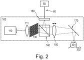
- FIG. 2 schematically shows an example of a handheld part 100 of the intraoral scanner according to an embodiment of this disclosure. It comprises a LED light source 110, a lens 111, a pattern 130 (a line in a true cross-sectional view, but shown here at an angle for clarity), a beam splitter 140, and an image sensor 180.
- the scanner is a focus scanner owing to a moveable lens 150.
- a mirror 170 that folds the beam path towards a part of the intraoral cavity being scanned, comprising a tooth 301 and gingiva 302.
- Also shown as dashed lines are some light rays emitted from the light source 110, transmitted through the optical system onto a location on the tooth surface where they focus, returned through the optical system, and imaged onto sensor 180, where they focus, too.
- some gingiva 302 is visible, but not in focus. It could come into focus for other positions of lens 150.
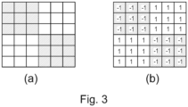
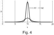
- Figures 3 and 4 show how data from the exemplary handheld scanner 100 are processed to yield distance maps.
- Figure 3(a) is a view of one spatial period checkerboard pattern 130 as seen by the image sensor 180 when the image of that spatial period on the scanned surface is in focus. In the extreme case of a completely defocused image of the pattern, the image sensor would see a uniform gray. It is advantageous if image sensor pixels and pattern are aligned such that the borders of the pattern are imaged to borders of pixels.
- a pixel group is in focus when A is at its maximum over all s, i.e., over all images in a series obtained within a pass of the focus lens.
- the location of that maximum determines the distance z( s ) to the measured surface, because the scanner's optics are known from construction and hence, the location of the focus plane for all pixel groups and all positions of lens 150 is known.
- the distance z( s ) can also be found from or refined by calibration.
- the distance z ( s ) for a given pixel group yields a point z ( x, y ).
- all pixel groups have same size, all locations ( x, y ) from a grid.
- the focus lens should be moved quickly so that a given pixel group at least approximately represents the same region of the scanned surface even in the presence of some hand motion.
- the focus lens can pass through all s with a cycle frequency of 10 Hz, travelling back and forth, so with 20 passes per second.
- the number of images during a pass should be rather high to yield good resolution of distance measurement, such as 200.
- the exemplary scanner provides distance maps with one z value per pixel group with coordinates ( x, y ) with associated certainty q , or being undefined.
- the combination of ( z , q ) ( x, y ) can be called an augmented distance map, analogous to an image with two channels.
- a full 3D representation of the scanned part of the intraoral cavity is then obtained by stitching the augmented distance maps obtained with various scanner poses.
- 3D scanners include triangulation 3D laser scanners and structured-light 3D scanners.
- a triangulation 3D laser scanner uses laser light to probe the environment or object.
- a triangulation laser shines a laser on the object and exploits a camera to look for the location of the laser dot. Depending on how far away the laser strikes a surface, the laser dot appears at different places in the camera's field of view. This technique is called triangulation because the laser dot, the camera and the laser emitter form a triangle.
- a laser stripe instead of a single laser dot, may be used and is then swept across the object to speed up the acquisition process.
- Structured-light 3D scanners project a pattern of light on the object and look at the deformation of the pattern on the object.
- the pattern may be one dimensional or two dimensional.
- An example of a one dimensional pattern is a line.
- the line is projected onto the object using e.g. an LCD projector or a sweeping laser.
- a camera offset slightly from the pattern projector, looks at the shape of the line and uses a technique similar to triangulation to calculate the distance of every point on the line.
- the line is swept across the field of view to gather distance information one strip at a time.
- Other 3D scanner principles are well known in the art.
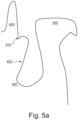
- FIG. 5a For an example of how to arrive at a set of surface types, reference is made to Figure 5a .
- the figure shows in a cross-sectional view the lower mouth, with an incisor tooth 600, its gingival margin 610, gingiva 630, and lower lip 650.
- One possible set of surface types would simply be according to these three types of tissue. However, for better training, it can be advantageous to reduce the number of surface types in the set.
- a general-purpose type of application that has the goal to record teeth and near gingiva, one can lump "tooth" with some near gingival tissue, e.g., up to point 620, with the remainder being a second surface type.
- the former is "desirable" for stitching, the latter is “undesirable”.
- Point 620 (a line in 3D) need not have anatomical meaning, but could, e.g., be set from the extent of the scanner's field of view when the scanner is imaging at least some part of a tooth. Any surface of a dental instrument, a finger, cotton pad, or other artifacts is also lumped into the "undesirable" type in this example.
- the scanner is used to create a digital 3D representation of a part of an intraoral cavity by recording multiple augmented distance maps that are stitched, as explained for Figures 1 to 4 .
- Some views and hence some augmented distance maps could contain a dental instrument, a finger, cotton pad, or other artifacts. These artifacts may at least partly be represented in the digital 3D representation, making that model a relatively poorer representation of the intraoral cavity.
- portions of the digital 3D representation are annotated by the surface type as defined above for Figure 5a .
- Annotation can, e.g., be performed by a human in a graphical user interface. Annotation could also be semi-automated, with the human receiving suggestions obtained with other methods, e.g., traditional image analysis algorithms.
- step 503 the annotated portions are projected back to the individual augmented distance maps, using the inverses of the transformations found in the stitching.
- This provides for class map c ( x , y ) for each augmented distance map, where c is a class indicator.
- c is a class indicator.
- one-hot encoding is used to arrive at a vector of scores p of a part of an augmented distance map belonging to any of the surface types of step 502.
- p the element for class c set to 1 and all others are set to zero.
- p has two elements, one for "desirable" and one for "undesirable”.
- the number of recordings m could also for example 10, 20, 50, 100, 200, 500 or 1000, or any number of recordings there between or higher.
- the recordings are similar with respect to the part of the intraoral cavity that is scanned, and they may also be similar with respect to artifacts in some views, affecting in an analogous way the m digital 3D representations created from the m recordings.
- a neural network is trained to predict p ( x, y ) for ( z , q ) ( x, y ).
- Uncertainty q is taken as the logarithm of the maximum value of A , as explained for Figure 4 .
- the scanner outputs a distance map that is defined on a rectangular grid as explained above, the augmented distance map ( z , q ) ( x, y ) can be interpreted as a two-channel rectangular image that becomes the input to the neural network.
- steps 501 - 504 could also be performed for single distance maps, for single augmented distance maps, both cases resulting in no stitching and trivial back-projections, or for multiple distance maps, albeit it is preferable to conduct them for multiple augmented distance maps as that constellation provides most information.
- training and prediction could be formulated as p ( x, y ) for ( z , q, r, g, b ) ( x, y ), where r, g, b are the red, green, and blue components of a color measurement; analogously for other or additional data provided by the scanner.
- Figure 6 shows an example architecture of a suitable convolutional neural network, with:
- the neural network has convolutional layers with small kernels, such as 3 x 3 x M, where M is the number of channels.
- M is the number of channels.
- the impact of surface point neighborhoods follows from the use of convolutional layers.
- the impact of wider neighborhoods follows from the use of max-pool layers.
- the output image has same width and height as the input image, so for every input surface data point, there is an output p .
- Figure 7 (a) shows a first example of how a trained machine learning algorithm is applied in inference mode.
- step 700 a set of surface types to predict is chosen. Only surface types defined during training, in step 502, can be chosen in step 700, but possibly some training types can be grouped. For the example at hand, it is assumed that training and inference sets are the same, with the two surface types “desirable” and “undesirable”. However, any number of surface types defined during training may be used.
- step 701 an augmented distance map ( z , q ) ( x, y ) is recorded.
- step 702 the score vector p ( x, y ) for ( z , q ) ( x, y ) is inferred for all points ( x, y ) in the recorded augmented distance map.
- the machine learning algorithm provides the inference.
- p ( x , y ) is given by the values with coordinates ( x, y ) in the multi-channel output image O, i.e., each channel provides one element of the vector p .
- w could be chosen as [1, 0] (the first element referring to the "desirable" surface type).
- step 704 the points z ( x, y ) are stitched to the digital 3D representation build from previous views, weighted according to their weights found in step 703. For example, a standard ICP algorithm is used for the stitching, and all points with w > 0 are included in the underlying minimization problem. For the very first view, the digital 3D representation is set to the points z ( x, y ).
- the procedure can then repeat from step 701 for additional views, typically taken from different poses as the operator moves the scanner, or it can terminate, typically if the operator decides the digital 3D representation is complete. That first digital 3D representation is then often converted to a second one, a mesh.
- Figure 7 (b) shows a second example of how a trained machine learning classification algorithm is applied in inference mode.
- Steps 700 to 702 are as in the first example of Figure 7 (a) .
- step 714 all points z ( x, y ) are stitched to an interim digital 3D representation built from previous views, and so are the values of p ( x, y ), thus receiving spatial coordinates in the space of the digital 3D representation as ( X , Y, Z ) and p ( X, Y, Z ), resp.
- the interim virtual model's 3D space is represented as voxels, and the values of p ( X, Y, Z ) are assigned to the nearest voxel.
- values of p are summed over views, and a count of how many values are added is maintained, such that, e.g., an average can be computed later.
- the procedure can then repeat from step 701 for additional views, typically taken from different poses as the operator moves the scanner, or it can terminate, typically if the operator decides the interim digital 3D representation is complete.
- step 713 weights are found in manner analogous to step 703, but for the average p , that average found by dividing the sum by the number of values. Voxels with weight 0 are filtered out, and so are voxels without any values.
- step 715 a final virtual model is built from the points ( X , Y, Z ) in the remaining voxels, e.g., using the marching cubes algorithm.
- Figure 8 shows an example of how the algorithm of Figure 7 (b) is expanded to also use filtering based on excluded volume. To begin with, the excluded volume is empty.
- Steps 700 - 702 and 714 are as explained above for figure 7 .
- the excluded volume is updated with the stitched points ( X , Y, Z ) from step 714.
- An excluded volume is, e.g., the space from a seen surface up to the scanner, and the scanner body. For practical purposes, exclusion could be expressed on the same voxel space as used in step 714.
- a binary flag can indicate whether a voxel is part of the excluded space.
- Step 701 The procedure can then repeat from step 701 for additional views as described above. As more views are recorded, the number of voxels that are flagged as being in the excluded space can grow, but never decrease. Step 713 is as explained above for figure 7 .
- step 813 all voxels that still contain values of summed p , but that are in the excluded volume, are deleted. This step is easiest to implement if the voxel spaces are identical; otherwise, a nearest-neighbor search can be used to find the closest voxel in the excluded volume voxel space.
- Step 715 is as explained above for figure 7 .
Landscapes
- Physics & Mathematics (AREA)
- Engineering & Computer Science (AREA)
- Health & Medical Sciences (AREA)
- Theoretical Computer Science (AREA)
- General Physics & Mathematics (AREA)
- Life Sciences & Earth Sciences (AREA)
- General Health & Medical Sciences (AREA)
- Software Systems (AREA)
- Evolutionary Computation (AREA)
- General Engineering & Computer Science (AREA)
- Biomedical Technology (AREA)
- Biophysics (AREA)
- Computational Linguistics (AREA)
- Data Mining & Analysis (AREA)
- Artificial Intelligence (AREA)
- Mathematical Physics (AREA)
- Molecular Biology (AREA)
- Computing Systems (AREA)
- Epidemiology (AREA)
- Optics & Photonics (AREA)
- Oral & Maxillofacial Surgery (AREA)
- Dentistry (AREA)
- Animal Behavior & Ethology (AREA)
- Public Health (AREA)
- Veterinary Medicine (AREA)
- Computer Vision & Pattern Recognition (AREA)
- Computer Graphics (AREA)
- Geometry (AREA)
- Dental Tools And Instruments Or Auxiliary Dental Instruments (AREA)
- Image Processing (AREA)
- Image Generation (AREA)
Claims (10)
- Verfahren zum Erzeugen einer digitalen 3D-Darstellung von mindestens einem Teil eines intraoralen Hohlraums, wobei das Verfahren umfasst:- Aufzeichnen einer Vielzahl von Ansichten, die Oberflächendaten enthalten, die mindestens die Geometrie von Oberflächenpunkten des Teils des intraoralen Hohlraums darstellen, durch Verwenden eines intraoralen Scanners;- Bestimmen einer Gewichtung für jeden Oberflächenpunkt zumindest teilweise basierend auf Bewertungen, die Messgrößen für eine Annahme sind, dass dieser Oberflächenpunkt eine bestimmte Art von Oberfläche darstellt;- Ausführen eines Stitching-Algorithmus, der ein gewichtetes Stitching der Oberflächenpunkte in der Vielzahl von Ansichten durchführt, um die digitale 3D-Darstellung basierend auf den bestimmten Gewichtungen zu erzeugen;- wobei die Bewertungen für die Oberflächenpunkte durch mindestens einen Bewertungsfindungsalgorithmus gefunden werden, der als Eingabe mindestens den Geometrieteil der Oberflächendaten für diesen Oberflächenpunkt und Oberflächendaten für Punkte in einer Nachbarschaft dieses Oberflächenpunkts annimmt;dadurch gekennzeichnet, dass der Scanner auch einige Gewissheitsinformationen über gemessene Oberflächendaten für die aufgezeichneten Ansichten liefert, und dass die Gewissheitsinformationen die Bewertungen zumindest teilweise modifizieren.
- Verfahren nach Anspruch 1, wobei der mindestens eine Bewertungsfindungsalgorithmus ein Algorithmus für maschinelles Lernen ist.
- Verfahren nach Anspruch 2, wobei der mindestens eine Algorithmus für maschinelles Lernen ein neuronales Netzwerk mit mindestens einer Faltungsebene umfasst.
- Verfahren nach Anspruch 2 oder 3, wobei der mindestens eine Algorithmus für maschinelles Lernen auf einer Vielzahl von Oberflächenarten eingelernt wurde, die üblicherweise mit Scannern in intraoralen Hohlräumen aufgezeichnet werden.
- Verfahren nach einem der vorstehenden Ansprüche, wobei die Oberflächendaten auch Farbinformationen umfassen.
- Verfahren nach einem der vorstehenden Ansprüche, wobei mindestens ein Algorithmus für maschinelles Lernen zumindest teilweise durch Verwenden von Daten eingelernt wurde, die von einem intraoralen Scanner vor dem Erzeugen der digitalen 3D-Darstellung aufgezeichnet wurden.
- Verfahren nach einem der vorstehenden Ansprüche, wobei mindestens ein Algorithmus für maschinelles Lernen zumindest teilweise von einem Bediener eines/des intraoralen Scanners eingelernt wurde.
- Verfahren nach einem der vorstehenden Ansprüche, wobei andere Algorithmen zum Filtern von Daten aus den aufgezeichneten Ansichten angewendet werden, wobei einer der anderen Algorithmen die geometrische Konsistenz über eine Vielzahl von Ansichten bewertet.
- Computerprogrammprodukt, das Anweisungen umfasst, die, wenn das Programm von einem Computer ausgeführt wird, den Computer veranlassen, die Schritte des Verfahrens nach einem der vorstehenden Ansprüche durchzuführen.
- Scanner-System zum Erzeugen einer digitalen 3D-Darstellung von mindestens einem Teil eines oralen Hohlraums, wobei das Scanner-System umfasst:- einen handgehaltenen intraoralen Scanner; und- eine oder mehrere Verarbeitungseinheiten, die dazu konfiguriert sind, die Schritte des Verfahrens nach einem der Ansprüche 1-8 durchzuführen.
Priority Applications (1)
| Application Number | Priority Date | Filing Date | Title |
|---|---|---|---|
| EP24170132.5A EP4375748A3 (de) | 2018-02-16 | 2019-02-08 | Intraorale abtastung mit oberflächendifferenzierung |
Applications Claiming Priority (2)
| Application Number | Priority Date | Filing Date | Title |
|---|---|---|---|
| DKPA201870094 | 2018-02-16 | ||
| PCT/EP2019/053138 WO2019158442A1 (en) | 2018-02-16 | 2019-02-08 | Intraoral scanning with surface differentiation |
Related Child Applications (1)
| Application Number | Title | Priority Date | Filing Date |
|---|---|---|---|
| EP24170132.5A Division EP4375748A3 (de) | 2018-02-16 | 2019-02-08 | Intraorale abtastung mit oberflächendifferenzierung |
Publications (2)
| Publication Number | Publication Date |
|---|---|
| EP3752982A1 EP3752982A1 (de) | 2020-12-23 |
| EP3752982B1 true EP3752982B1 (de) | 2024-04-24 |
Family
ID=65409074
Family Applications (2)
| Application Number | Title | Priority Date | Filing Date |
|---|---|---|---|
| EP19704779.8A Active EP3752982B1 (de) | 2018-02-16 | 2019-02-08 | Intraorale abtastung mit oberflächendifferenzierung |
| EP24170132.5A Pending EP4375748A3 (de) | 2018-02-16 | 2019-02-08 | Intraorale abtastung mit oberflächendifferenzierung |
Family Applications After (1)
| Application Number | Title | Priority Date | Filing Date |
|---|---|---|---|
| EP24170132.5A Pending EP4375748A3 (de) | 2018-02-16 | 2019-02-08 | Intraorale abtastung mit oberflächendifferenzierung |
Country Status (6)
| Country | Link |
|---|---|
| US (3) | US11974900B2 (de) |
| EP (2) | EP3752982B1 (de) |
| KR (1) | KR102724016B1 (de) |
| CN (1) | CN112106109B (de) |
| ES (1) | ES2981320T3 (de) |
| WO (1) | WO2019158442A1 (de) |
Families Citing this family (11)
| Publication number | Priority date | Publication date | Assignee | Title |
|---|---|---|---|---|
| US11896461B2 (en) * | 2018-06-22 | 2024-02-13 | Align Technology, Inc. | Intraoral 3D scanner employing multiple miniature cameras and multiple miniature pattern projectors |
| US11250580B2 (en) * | 2019-09-24 | 2022-02-15 | Dentsply Sirona Inc. | Method, system and computer readable storage media for registering intraoral measurements |
| US11291404B2 (en) * | 2019-09-24 | 2022-04-05 | Dentsply Sirona Inc. | Method, system and computer readable storage media for the detection of errors in three-dimensional measurements |
| KR102269897B1 (ko) * | 2020-01-08 | 2021-06-28 | 주식회사 메디트 | 이미지 필터링 방법 |
| US11842484B2 (en) | 2021-01-04 | 2023-12-12 | James R. Glidewell Dental Ceramics, Inc. | Teeth segmentation using neural networks |
| KR20220069655A (ko) * | 2020-11-20 | 2022-05-27 | 주식회사 쓰리디산업영상 | Ct 영상에서의 치아 분할 시스템 및 방법 |
| US12136208B2 (en) | 2021-03-31 | 2024-11-05 | James R. Glidewell Dental Ceramics, Inc. | Automatic clean up of jaw scans |
| US12210802B2 (en) | 2021-04-30 | 2025-01-28 | James R. Glidewell Dental Ceramics, Inc. | Neural network margin proposal |
| GB202107492D0 (en) | 2021-05-26 | 2021-07-07 | Vitaware Ltd | Image processing method |
| US20250064562A1 (en) | 2021-12-10 | 2025-02-27 | 3Shape A/S | Systems And Methods For Designing A Dental Prosthesis |
| US12295806B2 (en) | 2022-01-10 | 2025-05-13 | James R. Glidewell Dental Ceramics, Inc. | Automatic determination of trim-line for aligners |
Family Cites Families (14)
| Publication number | Priority date | Publication date | Assignee | Title |
|---|---|---|---|---|
| US20050089213A1 (en) * | 2003-10-23 | 2005-04-28 | Geng Z. J. | Method and apparatus for three-dimensional modeling via an image mosaic system |
| EP3443890A1 (de) | 2004-06-17 | 2019-02-20 | Align Technology, Inc. | Verfahren und system zur bereitstellung von daten im zusammenhang mit der intraoralen kavität |
| DE602005009432D1 (de) | 2004-06-17 | 2008-10-16 | Cadent Ltd | Verfahren und Gerät zur Farbbildformung einer dreidimensionalen Struktur |
| US7720267B2 (en) | 2005-07-15 | 2010-05-18 | Siemens Medical Solutions Usa, Inc. | Method and apparatus for classifying tissue using image data |
| US8170306B2 (en) | 2007-04-25 | 2012-05-01 | Siemens Aktiengesellschaft | Automatic partitioning and recognition of human body regions from an arbitrary scan coverage image |
| ES2607052T3 (es) | 2009-06-17 | 2017-03-29 | 3Shape A/S | Aparato de escaneo de enfoque |
| EP3401876B2 (de) | 2011-07-15 | 2022-08-17 | 3Shape A/S | Erkennung eines beweglichen objekts bei der 3d-abtastung eines starren objekts |
| JP6430934B2 (ja) | 2012-06-27 | 2018-11-28 | 3シェイプ アー/エス | 蛍光を測定する口腔内3dスキャナ |
| US8948482B2 (en) * | 2012-11-01 | 2015-02-03 | Align Technology, Inc. | Motion compensation in a three dimensional scan |
| ES2927626T3 (es) | 2013-02-13 | 2022-11-08 | 3Shape As | Aparato de escaneo de foco que graba el color |
| US10010387B2 (en) | 2014-02-07 | 2018-07-03 | 3Shape A/S | Detecting tooth shade |
| US9349178B1 (en) | 2014-11-24 | 2016-05-24 | Siemens Aktiengesellschaft | Synthetic data-driven hemodynamic determination in medical imaging |
| EP3086283B1 (de) * | 2015-04-21 | 2019-01-16 | Hexagon Technology Center GmbH | Bereitstellung einer point-cloud unter verwendung eines vermessungsinstruments und einer kameravorrichtung |
| WO2018125938A1 (en) * | 2016-12-30 | 2018-07-05 | DeepMap Inc. | Enrichment of point cloud data for high-definition maps for autonomous vehicles |
-
2019
- 2019-02-08 WO PCT/EP2019/053138 patent/WO2019158442A1/en not_active Ceased
- 2019-02-08 EP EP19704779.8A patent/EP3752982B1/de active Active
- 2019-02-08 US US16/970,036 patent/US11974900B2/en active Active
- 2019-02-08 EP EP24170132.5A patent/EP4375748A3/de active Pending
- 2019-02-08 CN CN201980026060.1A patent/CN112106109B/zh active Active
- 2019-02-08 ES ES19704779T patent/ES2981320T3/es active Active
- 2019-02-08 KR KR1020207026369A patent/KR102724016B1/ko active Active
-
2024
- 2024-03-18 US US18/608,267 patent/US12350127B2/en active Active
-
2025
- 2025-06-05 US US19/229,057 patent/US20250295481A1/en active Pending
Also Published As
| Publication number | Publication date |
|---|---|
| CN112106109B (zh) | 2024-11-12 |
| EP4375748A2 (de) | 2024-05-29 |
| US20240252289A1 (en) | 2024-08-01 |
| KR102724016B1 (ko) | 2024-10-29 |
| US12350127B2 (en) | 2025-07-08 |
| KR20200123160A (ko) | 2020-10-28 |
| EP3752982A1 (de) | 2020-12-23 |
| ES2981320T3 (es) | 2024-10-08 |
| US11974900B2 (en) | 2024-05-07 |
| US20210106409A1 (en) | 2021-04-15 |
| US20250295481A1 (en) | 2025-09-25 |
| WO2019158442A1 (en) | 2019-08-22 |
| CN112106109A (zh) | 2020-12-18 |
| EP4375748A3 (de) | 2024-08-21 |
Similar Documents
| Publication | Publication Date | Title |
|---|---|---|
| US12350127B2 (en) | Intraoral scanning with surface differentiation | |
| JP7289026B2 (ja) | ハイブリッドメッシュセグメンテーションのための方法及び装置 | |
| KR102932237B1 (ko) | 디지털 3 차원 치과적 모델들을 생성하기 위한 시스템 및 방법 | |
| US11250580B2 (en) | Method, system and computer readable storage media for registering intraoral measurements | |
| US10339649B2 (en) | Method and system for hybrid mesh segmentation | |
| CN118175973A (zh) | 口内扫描仪实时和扫描后可视化 | |
| EP4074259A1 (de) | Verfahren und vorrichtung zur automatischen erkennung von merkmalspunkten von dreidimensionalen medizinischen bilddaten unter verwendung von tiefenlernen | |
| US20210322138A1 (en) | Hybrid method of acquiring 3d data using intraoral scanner | |
| WO2023156447A1 (en) | Method of generating a training data set for determining periodontal structures of a patient | |
| JP7709476B2 (ja) | 支援装置、支援方法、および支援プログラム | |
| WO2020037582A1 (en) | Graph-based key frame selection for 3-d scanning | |
| Procházka et al. | Computational Intelligence and Augmented Reality in Stomatology | |
| WO2026046851A1 (en) | Method for determining an epicenter of dental conditions | |
| CN120604268A (zh) | 根据模型数据生成牙科渲染 |
Legal Events
| Date | Code | Title | Description |
|---|---|---|---|
| STAA | Information on the status of an ep patent application or granted ep patent |
Free format text: STATUS: UNKNOWN |
|
| STAA | Information on the status of an ep patent application or granted ep patent |
Free format text: STATUS: THE INTERNATIONAL PUBLICATION HAS BEEN MADE |
|
| PUAI | Public reference made under article 153(3) epc to a published international application that has entered the european phase |
Free format text: ORIGINAL CODE: 0009012 |
|
| STAA | Information on the status of an ep patent application or granted ep patent |
Free format text: STATUS: REQUEST FOR EXAMINATION WAS MADE |
|
| 17P | Request for examination filed |
Effective date: 20200915 |
|
| AK | Designated contracting states |
Kind code of ref document: A1 Designated state(s): AL AT BE BG CH CY CZ DE DK EE ES FI FR GB GR HR HU IE IS IT LI LT LU LV MC MK MT NL NO PL PT RO RS SE SI SK SM TR |
|
| AX | Request for extension of the european patent |
Extension state: BA ME |
|
| DAV | Request for validation of the european patent (deleted) | ||
| DAX | Request for extension of the european patent (deleted) | ||
| RIC1 | Information provided on ipc code assigned before grant |
Ipc: G03B 37/02 20060101ALI20230413BHEP Ipc: G03B 35/02 20060101ALI20230413BHEP Ipc: A61C 9/00 20060101ALI20230413BHEP Ipc: G06T 7/55 20170101AFI20230413BHEP |
|
| GRAP | Despatch of communication of intention to grant a patent |
Free format text: ORIGINAL CODE: EPIDOSNIGR1 |
|
| STAA | Information on the status of an ep patent application or granted ep patent |
Free format text: STATUS: GRANT OF PATENT IS INTENDED |
|
| INTG | Intention to grant announced |
Effective date: 20230606 |
|
| GRAJ | Information related to disapproval of communication of intention to grant by the applicant or resumption of examination proceedings by the epo deleted |
Free format text: ORIGINAL CODE: EPIDOSDIGR1 |
|
| STAA | Information on the status of an ep patent application or granted ep patent |
Free format text: STATUS: REQUEST FOR EXAMINATION WAS MADE |
|
| GRAS | Grant fee paid |
Free format text: ORIGINAL CODE: EPIDOSNIGR3 |
|
| INTC | Intention to grant announced (deleted) | ||
| STAA | Information on the status of an ep patent application or granted ep patent |
Free format text: STATUS: GRANT OF PATENT IS INTENDED |
|
| GRAP | Despatch of communication of intention to grant a patent |
Free format text: ORIGINAL CODE: EPIDOSNIGR1 |
|
| P01 | Opt-out of the competence of the unified patent court (upc) registered |
Effective date: 20231027 |
|
| INTG | Intention to grant announced |
Effective date: 20231130 |
|
| GRAA | (expected) grant |
Free format text: ORIGINAL CODE: 0009210 |
|
| STAA | Information on the status of an ep patent application or granted ep patent |
Free format text: STATUS: THE PATENT HAS BEEN GRANTED |
|
| AK | Designated contracting states |
Kind code of ref document: B1 Designated state(s): AL AT BE BG CH CY CZ DE DK EE ES FI FR GB GR HR HU IE IS IT LI LT LU LV MC MK MT NL NO PL PT RO RS SE SI SK SM TR |
|
| REG | Reference to a national code |
Ref country code: GB Ref legal event code: FG4D |
|
| REG | Reference to a national code |
Ref country code: CH Ref legal event code: EP |
|
| REG | Reference to a national code |
Ref country code: DE Ref legal event code: R096 Ref document number: 602019050818 Country of ref document: DE |
|
| REG | Reference to a national code |
Ref country code: IE Ref legal event code: FG4D |
|
| REG | Reference to a national code |
Ref country code: LT Ref legal event code: MG9D |
|
| REG | Reference to a national code |
Ref country code: NL Ref legal event code: MP Effective date: 20240424 |
|
| REG | Reference to a national code |
Ref country code: AT Ref legal event code: MK05 Ref document number: 1680443 Country of ref document: AT Kind code of ref document: T Effective date: 20240424 |
|
| PG25 | Lapsed in a contracting state [announced via postgrant information from national office to epo] |
Ref country code: NL Free format text: LAPSE BECAUSE OF FAILURE TO SUBMIT A TRANSLATION OF THE DESCRIPTION OR TO PAY THE FEE WITHIN THE PRESCRIBED TIME-LIMIT Effective date: 20240424 |
|
| PG25 | Lapsed in a contracting state [announced via postgrant information from national office to epo] |
Ref country code: NL Free format text: LAPSE BECAUSE OF FAILURE TO SUBMIT A TRANSLATION OF THE DESCRIPTION OR TO PAY THE FEE WITHIN THE PRESCRIBED TIME-LIMIT Effective date: 20240424 |
|
| PG25 | Lapsed in a contracting state [announced via postgrant information from national office to epo] |
Ref country code: IS Free format text: LAPSE BECAUSE OF FAILURE TO SUBMIT A TRANSLATION OF THE DESCRIPTION OR TO PAY THE FEE WITHIN THE PRESCRIBED TIME-LIMIT Effective date: 20240824 |
|
| PG25 | Lapsed in a contracting state [announced via postgrant information from national office to epo] |
Ref country code: BG Free format text: LAPSE BECAUSE OF FAILURE TO SUBMIT A TRANSLATION OF THE DESCRIPTION OR TO PAY THE FEE WITHIN THE PRESCRIBED TIME-LIMIT Effective date: 20240424 |
|
| REG | Reference to a national code |
Ref country code: ES Ref legal event code: FG2A Ref document number: 2981320 Country of ref document: ES Kind code of ref document: T3 Effective date: 20241008 |
|
| PG25 | Lapsed in a contracting state [announced via postgrant information from national office to epo] |
Ref country code: HR Free format text: LAPSE BECAUSE OF FAILURE TO SUBMIT A TRANSLATION OF THE DESCRIPTION OR TO PAY THE FEE WITHIN THE PRESCRIBED TIME-LIMIT Effective date: 20240424 Ref country code: FI Free format text: LAPSE BECAUSE OF FAILURE TO SUBMIT A TRANSLATION OF THE DESCRIPTION OR TO PAY THE FEE WITHIN THE PRESCRIBED TIME-LIMIT Effective date: 20240424 |
|
| PG25 | Lapsed in a contracting state [announced via postgrant information from national office to epo] |
Ref country code: GR Free format text: LAPSE BECAUSE OF FAILURE TO SUBMIT A TRANSLATION OF THE DESCRIPTION OR TO PAY THE FEE WITHIN THE PRESCRIBED TIME-LIMIT Effective date: 20240725 |
|
| PG25 | Lapsed in a contracting state [announced via postgrant information from national office to epo] |
Ref country code: PT Free format text: LAPSE BECAUSE OF FAILURE TO SUBMIT A TRANSLATION OF THE DESCRIPTION OR TO PAY THE FEE WITHIN THE PRESCRIBED TIME-LIMIT Effective date: 20240826 |
|
| PG25 | Lapsed in a contracting state [announced via postgrant information from national office to epo] |
Ref country code: AT Free format text: LAPSE BECAUSE OF FAILURE TO SUBMIT A TRANSLATION OF THE DESCRIPTION OR TO PAY THE FEE WITHIN THE PRESCRIBED TIME-LIMIT Effective date: 20240424 |
|
| PG25 | Lapsed in a contracting state [announced via postgrant information from national office to epo] |
Ref country code: PL Free format text: LAPSE BECAUSE OF FAILURE TO SUBMIT A TRANSLATION OF THE DESCRIPTION OR TO PAY THE FEE WITHIN THE PRESCRIBED TIME-LIMIT Effective date: 20240424 |
|
| PG25 | Lapsed in a contracting state [announced via postgrant information from national office to epo] |
Ref country code: LV Free format text: LAPSE BECAUSE OF FAILURE TO SUBMIT A TRANSLATION OF THE DESCRIPTION OR TO PAY THE FEE WITHIN THE PRESCRIBED TIME-LIMIT Effective date: 20240424 |
|
| PG25 | Lapsed in a contracting state [announced via postgrant information from national office to epo] |
Ref country code: PT Free format text: LAPSE BECAUSE OF FAILURE TO SUBMIT A TRANSLATION OF THE DESCRIPTION OR TO PAY THE FEE WITHIN THE PRESCRIBED TIME-LIMIT Effective date: 20240826 Ref country code: PL Free format text: LAPSE BECAUSE OF FAILURE TO SUBMIT A TRANSLATION OF THE DESCRIPTION OR TO PAY THE FEE WITHIN THE PRESCRIBED TIME-LIMIT Effective date: 20240424 Ref country code: NO Free format text: LAPSE BECAUSE OF FAILURE TO SUBMIT A TRANSLATION OF THE DESCRIPTION OR TO PAY THE FEE WITHIN THE PRESCRIBED TIME-LIMIT Effective date: 20240724 Ref country code: LV Free format text: LAPSE BECAUSE OF FAILURE TO SUBMIT A TRANSLATION OF THE DESCRIPTION OR TO PAY THE FEE WITHIN THE PRESCRIBED TIME-LIMIT Effective date: 20240424 Ref country code: IS Free format text: LAPSE BECAUSE OF FAILURE TO SUBMIT A TRANSLATION OF THE DESCRIPTION OR TO PAY THE FEE WITHIN THE PRESCRIBED TIME-LIMIT Effective date: 20240824 Ref country code: HR Free format text: LAPSE BECAUSE OF FAILURE TO SUBMIT A TRANSLATION OF THE DESCRIPTION OR TO PAY THE FEE WITHIN THE PRESCRIBED TIME-LIMIT Effective date: 20240424 Ref country code: GR Free format text: LAPSE BECAUSE OF FAILURE TO SUBMIT A TRANSLATION OF THE DESCRIPTION OR TO PAY THE FEE WITHIN THE PRESCRIBED TIME-LIMIT Effective date: 20240725 Ref country code: FI Free format text: LAPSE BECAUSE OF FAILURE TO SUBMIT A TRANSLATION OF THE DESCRIPTION OR TO PAY THE FEE WITHIN THE PRESCRIBED TIME-LIMIT Effective date: 20240424 Ref country code: BG Free format text: LAPSE BECAUSE OF FAILURE TO SUBMIT A TRANSLATION OF THE DESCRIPTION OR TO PAY THE FEE WITHIN THE PRESCRIBED TIME-LIMIT Effective date: 20240424 Ref country code: AT Free format text: LAPSE BECAUSE OF FAILURE TO SUBMIT A TRANSLATION OF THE DESCRIPTION OR TO PAY THE FEE WITHIN THE PRESCRIBED TIME-LIMIT Effective date: 20240424 Ref country code: RS Free format text: LAPSE BECAUSE OF FAILURE TO SUBMIT A TRANSLATION OF THE DESCRIPTION OR TO PAY THE FEE WITHIN THE PRESCRIBED TIME-LIMIT Effective date: 20240724 |
|
| PG25 | Lapsed in a contracting state [announced via postgrant information from national office to epo] |
Ref country code: DK Free format text: LAPSE BECAUSE OF FAILURE TO SUBMIT A TRANSLATION OF THE DESCRIPTION OR TO PAY THE FEE WITHIN THE PRESCRIBED TIME-LIMIT Effective date: 20240424 |
|
| PG25 | Lapsed in a contracting state [announced via postgrant information from national office to epo] |
Ref country code: EE Free format text: LAPSE BECAUSE OF FAILURE TO SUBMIT A TRANSLATION OF THE DESCRIPTION OR TO PAY THE FEE WITHIN THE PRESCRIBED TIME-LIMIT Effective date: 20240424 |
|
| PG25 | Lapsed in a contracting state [announced via postgrant information from national office to epo] |
Ref country code: CZ Free format text: LAPSE BECAUSE OF FAILURE TO SUBMIT A TRANSLATION OF THE DESCRIPTION OR TO PAY THE FEE WITHIN THE PRESCRIBED TIME-LIMIT Effective date: 20240424 |
|
| PG25 | Lapsed in a contracting state [announced via postgrant information from national office to epo] |
Ref country code: SK Free format text: LAPSE BECAUSE OF FAILURE TO SUBMIT A TRANSLATION OF THE DESCRIPTION OR TO PAY THE FEE WITHIN THE PRESCRIBED TIME-LIMIT Effective date: 20240424 Ref country code: RO Free format text: LAPSE BECAUSE OF FAILURE TO SUBMIT A TRANSLATION OF THE DESCRIPTION OR TO PAY THE FEE WITHIN THE PRESCRIBED TIME-LIMIT Effective date: 20240424 |
|
| REG | Reference to a national code |
Ref country code: DE Ref legal event code: R097 Ref document number: 602019050818 Country of ref document: DE |
|
| PG25 | Lapsed in a contracting state [announced via postgrant information from national office to epo] |
Ref country code: SM Free format text: LAPSE BECAUSE OF FAILURE TO SUBMIT A TRANSLATION OF THE DESCRIPTION OR TO PAY THE FEE WITHIN THE PRESCRIBED TIME-LIMIT Effective date: 20240424 |
|
| PG25 | Lapsed in a contracting state [announced via postgrant information from national office to epo] |
Ref country code: SM Free format text: LAPSE BECAUSE OF FAILURE TO SUBMIT A TRANSLATION OF THE DESCRIPTION OR TO PAY THE FEE WITHIN THE PRESCRIBED TIME-LIMIT Effective date: 20240424 Ref country code: SK Free format text: LAPSE BECAUSE OF FAILURE TO SUBMIT A TRANSLATION OF THE DESCRIPTION OR TO PAY THE FEE WITHIN THE PRESCRIBED TIME-LIMIT Effective date: 20240424 Ref country code: RO Free format text: LAPSE BECAUSE OF FAILURE TO SUBMIT A TRANSLATION OF THE DESCRIPTION OR TO PAY THE FEE WITHIN THE PRESCRIBED TIME-LIMIT Effective date: 20240424 Ref country code: EE Free format text: LAPSE BECAUSE OF FAILURE TO SUBMIT A TRANSLATION OF THE DESCRIPTION OR TO PAY THE FEE WITHIN THE PRESCRIBED TIME-LIMIT Effective date: 20240424 Ref country code: DK Free format text: LAPSE BECAUSE OF FAILURE TO SUBMIT A TRANSLATION OF THE DESCRIPTION OR TO PAY THE FEE WITHIN THE PRESCRIBED TIME-LIMIT Effective date: 20240424 Ref country code: CZ Free format text: LAPSE BECAUSE OF FAILURE TO SUBMIT A TRANSLATION OF THE DESCRIPTION OR TO PAY THE FEE WITHIN THE PRESCRIBED TIME-LIMIT Effective date: 20240424 |
|
| PLBE | No opposition filed within time limit |
Free format text: ORIGINAL CODE: 0009261 |
|
| STAA | Information on the status of an ep patent application or granted ep patent |
Free format text: STATUS: NO OPPOSITION FILED WITHIN TIME LIMIT |
|
| 26N | No opposition filed |
Effective date: 20250127 |
|
| PG25 | Lapsed in a contracting state [announced via postgrant information from national office to epo] |
Ref country code: SI Free format text: LAPSE BECAUSE OF FAILURE TO SUBMIT A TRANSLATION OF THE DESCRIPTION OR TO PAY THE FEE WITHIN THE PRESCRIBED TIME-LIMIT Effective date: 20240424 |
|
| PGFP | Annual fee paid to national office [announced via postgrant information from national office to epo] |
Ref country code: ES Payment date: 20250331 Year of fee payment: 7 |
|
| PG25 | Lapsed in a contracting state [announced via postgrant information from national office to epo] |
Ref country code: SE Free format text: LAPSE BECAUSE OF FAILURE TO SUBMIT A TRANSLATION OF THE DESCRIPTION OR TO PAY THE FEE WITHIN THE PRESCRIBED TIME-LIMIT Effective date: 20240424 |
|
| PG25 | Lapsed in a contracting state [announced via postgrant information from national office to epo] |
Ref country code: MC Free format text: LAPSE BECAUSE OF FAILURE TO SUBMIT A TRANSLATION OF THE DESCRIPTION OR TO PAY THE FEE WITHIN THE PRESCRIBED TIME-LIMIT Effective date: 20240424 |
|
| REG | Reference to a national code |
Ref country code: CH Ref legal event code: PL |
|
| PG25 | Lapsed in a contracting state [announced via postgrant information from national office to epo] |
Ref country code: LU Free format text: LAPSE BECAUSE OF NON-PAYMENT OF DUE FEES Effective date: 20250208 |
|
| PG25 | Lapsed in a contracting state [announced via postgrant information from national office to epo] |
Ref country code: CH Free format text: LAPSE BECAUSE OF NON-PAYMENT OF DUE FEES Effective date: 20250228 |
|
| REG | Reference to a national code |
Ref country code: BE Ref legal event code: MM Effective date: 20250228 |
|
| PG25 | Lapsed in a contracting state [announced via postgrant information from national office to epo] |
Ref country code: IT Free format text: LAPSE BECAUSE OF NON-PAYMENT OF DUE FEES Effective date: 20250208 |
|
| PG25 | Lapsed in a contracting state [announced via postgrant information from national office to epo] |
Ref country code: BE Free format text: LAPSE BECAUSE OF NON-PAYMENT OF DUE FEES Effective date: 20250228 |
|
| PG25 | Lapsed in a contracting state [announced via postgrant information from national office to epo] |
Ref country code: IE Free format text: LAPSE BECAUSE OF NON-PAYMENT OF DUE FEES Effective date: 20250208 |
|
| PGFP | Annual fee paid to national office [announced via postgrant information from national office to epo] |
Ref country code: GB Payment date: 20260220 Year of fee payment: 8 |
|
| PGFP | Annual fee paid to national office [announced via postgrant information from national office to epo] |
Ref country code: DE Payment date: 20260218 Year of fee payment: 8 |
|
| PG25 | Lapsed in a contracting state [announced via postgrant information from national office to epo] |
Ref country code: IT Free format text: LAPSE BECAUSE OF NON-PAYMENT OF DUE FEES Effective date: 20250208 |
|
| PGFP | Annual fee paid to national office [announced via postgrant information from national office to epo] |
Ref country code: IT Payment date: 20260224 Year of fee payment: 8 |
|
| PGRI | Patent reinstated in contracting state [announced from national office to epo] |
Ref country code: IT Effective date: 20250630 |
|
| PGFP | Annual fee paid to national office [announced via postgrant information from national office to epo] |
Ref country code: FR Payment date: 20260218 Year of fee payment: 8 |