EP3753677A1 - Verbindungsgestänge für schraubbohrmeissel und an eine pleuelstange angepasste hülsenanordnung - Google Patents
Verbindungsgestänge für schraubbohrmeissel und an eine pleuelstange angepasste hülsenanordnung Download PDFInfo
- Publication number
- EP3753677A1 EP3753677A1 EP19787757.4A EP19787757A EP3753677A1 EP 3753677 A1 EP3753677 A1 EP 3753677A1 EP 19787757 A EP19787757 A EP 19787757A EP 3753677 A1 EP3753677 A1 EP 3753677A1
- Authority
- EP
- European Patent Office
- Prior art keywords
- connecting rod
- sleeve
- sleeve body
- assembly
- locking member
- Prior art date
- Legal status (The legal status is an assumption and is not a legal conclusion. Google has not performed a legal analysis and makes no representation as to the accuracy of the status listed.)
- Withdrawn
Links
Images



Classifications
-
- B—PERFORMING OPERATIONS; TRANSPORTING
- B25—HAND TOOLS; PORTABLE POWER-DRIVEN TOOLS; MANIPULATORS
- B25B—TOOLS OR BENCH DEVICES NOT OTHERWISE PROVIDED FOR, FOR FASTENING, CONNECTING, DISENGAGING, OR HOLDING
- B25B23/00—Details of, or accessories for, spanners, wrenches, screwdrivers
- B25B23/0007—Connections or joints between tool parts
- B25B23/0035—Connection means between socket or screwdriver bit and tool
-
- B—PERFORMING OPERATIONS; TRANSPORTING
- B25—HAND TOOLS; PORTABLE POWER-DRIVEN TOOLS; MANIPULATORS
- B25B—TOOLS OR BENCH DEVICES NOT OTHERWISE PROVIDED FOR, FOR FASTENING, CONNECTING, DISENGAGING, OR HOLDING
- B25B23/00—Details of, or accessories for, spanners, wrenches, screwdrivers
- B25B23/02—Arrangements for handling screws or nuts
- B25B23/08—Arrangements for handling screws or nuts for holding or positioning screw or nut prior to or during its rotation
- B25B23/12—Arrangements for handling screws or nuts for holding or positioning screw or nut prior to or during its rotation using magnetic means
-
- B—PERFORMING OPERATIONS; TRANSPORTING
- B25—HAND TOOLS; PORTABLE POWER-DRIVEN TOOLS; MANIPULATORS
- B25B—TOOLS OR BENCH DEVICES NOT OTHERWISE PROVIDED FOR, FOR FASTENING, CONNECTING, DISENGAGING, OR HOLDING
- B25B21/00—Portable power-driven screw or nut setting or loosening tools; Attachments for drilling apparatus serving the same purpose
Definitions
- the present disclosure relates to an accessory device, in particular, a connecting rod assembly for a screwdriver bit and a sleeve assembly adapted to a connecting rod.
- a screwdriver bit When a power tool is in service, a screwdriver bit is often fitted to a connecting rod for use, and some connecting rods are also fitted to a sleeve to form a connecting rod assembly.
- frequently-used connecting rod assemblies with a magnetic nail-holding mechanism do not have a locking function for a screwdriver bit, thus the screwdriver bit is easily disengaged from the connecting rod assembly.
- most of the sleeves fitted with the connecting rods have non-detachable structures, which limit an application range of the connecting rod and the sleeve and cause waste when the connecting rod assembly is partially damaged.
- an object of the present disclosure is to provide a novel sleeve-detachable connecting rod assembly, which also has a locking function for a screwdriver bit.
- the present disclosure adopts the following technical solutions.
- a connecting rod assembly for the screwdriver bit including a connecting rod, one end of which is formed with a transmission slot capable of being fitted with the screwdriver bit, and another end of which is formed with a transmission shank for receiving power to rotate around a central axis.
- the connecting rod assembly further includes a sleeve assembly movably connected to the connecting rod.
- the sleeve assembly includes a sleeve body, a functional body, and a locking member; where the sleeve body extends along the central axis and is sleeved to an end of the connecting rod and is formed with a through hole through which at least part of the screwdriver bit passes; the functional body is connected to the sleeve body to realize a function of the sleeve assembly; the locking member is movably coupled to the sleeve body, and at least has a locking position and an unlocking position relative to the sleeve body.
- the sleeve assembly and the connecting rod form a non-detachable connection when the sleeve assembly is subjected to an axial force less than a first axial force; and when the locking member is in the unlocking position, the sleeve assembly and the connecting rod form a detachable connection when the sleeve assembly is subjected to an axial force greater than a second axial force, where the first axial force is greater than the second axial force.
- an end of the sleeve body is connected to or formed with an elastic portion capable of elastic deformation in a direction perpendicular to the central axis.
- the elastic portion in condition that the locking member is switched from the unlocking position toward the locking position, the elastic portion is configured to contract inward with the central axis as a center; and in condition that the locking member is switched from the locking position toward the unlocking position, the elastic portion is configured to expand outward with the central axis as the center.
- the sleeve body is further connected to or formed with a stopper configured for stopping the locking member from being disengaged from the sleeve body along the central axis.
- the connecting rod is formed with a stepped structure; and the elastic portion is formed with a stopper that is capable of cooperating with the step to prevent the sleeve assembly from being disengaged from the connecting rod along the central axis.
- the connecting rod is inserted into the sleeve body along a first direction parallel to the central axis, and the sleeve body is further connected to or formed with a limiting portion that prevents the connecting rod from continuing to move relative to the sleeve body along the first direction.
- the functional body at least includes a magnetic portion capable of attracting the screwdriver bit.
- the functional body is disposed at an end of the sleeve body opposite to the elastic portion.
- the sleeve body is further formed with an accommodation portion configured to accommodate at least part of the function body.
- the magnetic portion is symmetrically distributed about the central axis.
- part of the connecting rod is located inside the sleeve body; the connecting rod at least has a first position and a second position relative to the sleeve assembly along the central axis; in condition that the connecting rod is in the first position relative to the sleeve assembly, an end of the connecting rod is abutted against a limiting portion; in condition that the connecting rod is in the second position relative to the sleeve assembly, the connecting rod is disengaged from the limiting portion; and the magnetic portion is configured to generate a magnetic force capable of driving the connecting rod to move toward the first position.
- the screwdriver bit at least has a connection position and a disengagement position relative to the connecting rod; when at the connection position, the screwdriver bit is accommodated in the transmission slot and abuts against the connecting rod, and when at the disengagement position, the screwdriver bit is disengaged from the connecting rod; and the connecting rod is configured to generate a magnetic force capable of driving the screwdriver bit to move toward the connection position.
- the connecting rod is made of a magnetic material capable of attracting the screwdriver bit.
- the transmission slot is connected to or integrally formed with a magnetic material capable of attracting the screwdriver bit.
- the sleeve assembly is formed with a stopping portion configured for preventing the screwdriver bit from being disengaged from the connecting rod, and a distance from the stopping portion to the central axis is less than 3 mm.
- the sleeve body further includes a sliding groove located on an outer surface of the sleeve body, and the locking member is slidably disposed in the sliding groove.
- the sleeve body is made of a plastic material.
- the elastic portion is made of a plastic material.
- the elastic portion includes a plurality of claw portions extending along the central axis and symmetrically arranged about the central axis, and an end of a respective claw portion is fixedly connected to the sleeve body.
- a connecting rod assembly for the screwdriver bit including a connecting rod, an end of which is formed with the transmission slot capable of being fitted with the screwdriver bit, and another end of which is formed with the transmission shank for receiving power to rotate around the central axis.
- the connecting rod assembly further includes a sleeve assembly movably connected to the connecting rod.
- the sleeve assembly includes the sleeve body, the functional body, and the locking member; where the sleeve body extends along the central axis and is sleeved to an end of the connecting rod and is formed with the through hole through which at least part of the screwdriver bit passes; the functional body is connected to the sleeve body; the locking member is connected to the sleeve body, and at least has a locked state and an unlocked state relative to the sleeve body.
- the sleeve assembly When the locking member is in the locked state relative to the sleeve body, the sleeve assembly is non-detachable relative to the connecting rod; and when the locking member is in the unlocked state relative to the sleeve body, the sleeve assembly is detachable relative to the connecting rod.
- a sleeve assembly adapted to a connecting rod, including the sleeve body, the functional body, and the locking member; where the sleeve body extends along the central axis and is sleeved to an end of the connecting rod and is formed with a through hole through which at least part of the screwdriver bit passes; the functional body is connected to the sleeve body to realize a function of the sleeve assembly; the locking member is movably coupled to the sleeve body, and at least has the locking position and the unlocking position relative to the sleeve body.
- the sleeve assembly and the connecting rod form the non-detachable connection when the sleeve assembly is subjected to an axial force less than the first axial force; and when the locking member is in the unlocking position, the sleeve assembly and the connecting rod form the detachable connection when the sleeve assembly is subjected to the axial force greater than the second axial force, where the first axial force is greater than the second axial force.
- a sleeve assembly adapted to the connecting rod, including the sleeve assembly, which extends along the central axis and is sleeved to an end of the connecting rod and is formed with the through hole through which at least part of the screwdriver bit passes; the functional body connected to the sleeve body to realize the function of the sleeve assembly; where the sleeve assembly further includes the locking member, connected to the sleeve body, and at least has the locked state and the unlocked state relative to the sleeve body.
- the sleeve assembly When the locking member is in the locked state relative to the sleeve body, the sleeve assembly is non-detachable from the connecting rod, and when the locking member is in the unlocked state relative to the sleeve body, the sleeve assembly is detachable relative to the connecting rod.
- the present disclosure is beneficial in that the sleeve of the connecting rod assembly is detachable and the connecting rod assembly has a locking function for the screwdriver bit.
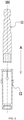
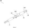
- a connecting rod assembly 100 may include a connecting rod 11 and a sleeve assembly 12 capable of being sleeved onto the connecting rod 11.
- the sleeve assembly 12 may be adapted to different specifications or types of the connecting rod 11, after the sleeve assembly 12 is installed on the connecting rod 11, the entirety of the sleeve assembly 12 and the connecting rod 11 is adapted to the screwdriver bit, which may realize a nail-holding effect on the screw.
- the sleeve assembly 12 is movably connected to the connecting rod 11.
- the sleeve assembly 12 is coaxially sleeved onto an end of the connecting rod 11 along a central axis 101.
- the connecting rod 11 is rotatable relative to the sleeve assembly 12 with the central axis 101 as an axis, and the connecting rod 11 is also slidable forward and backward along the central axis 101 relative to the sleeve assembly 12.
- a sleeve assembly 12 includes a sleeve body 121, a functional body 122, and a locking member 123.
- the sleeve body 121 extends along a central axis 101 and is sleeved onto an end of the connecting rod 11 facing toward a transmission slot 111 and is formed with a through hole 1211 through which a screwdriver bit passes.
- the functional body 122 is fixedly connected to the sleeve body 121.
- the locking member 123 is coaxially and movably sleeved onto the sleeve body 121, and has a locking position and an unlocking position relative to the sleeve body 121.
- the sleeve assembly 12 and the connecting rod 11 form a non-detachable connection when the sleeve assembly is subjected to an axial force less than a first axial force; and when the locking member is in the unlocking position, the sleeve assembly and the connecting rod form a detachable connection when the sleeve assembly is subjected to a axial force greater than a second axial force, where the first axial force is greater than the second axial force.
- the sleeve body 12 is made of plastic.
- An elastic portion 1212 capable of having elastic deformation in a direction perpendicular to the central axis 101 is connected or formed at an end of the sleeve body 121 facing toward the through hole 1211.
- the elastic portion 1212 is a part of the sleeve body 121, and the elastic portion 1212 may be integrally formed with the sleeve body 121 or may be fixedly or detachably connected to the sleeve body 121.
- the elastic portion 1212 includes an opening 12121 and a claw portion 12122. The opening 12121 and the claw portion 12122 are spaced apart along a circumferential direction of the sleeve body 121.
- a plurality of openings 12121 and a plurality of claw portions 12122 are symmetrical about the central axis 101 and are uniformly arranged in the circumferential direction of the sleeve body 121, respectively.
- the plurality of claw portions 12122 extend along the central axis 101 and are generally arc-shaped, and are fixedly connected to the sleeve body 121.
- the opening 12121 forms a hollow as shown in FIG. 4 on a surface of the sleeve body 121, and enables the elastic portion 1212 to have greater elastic deformation with the center axis 101 as a center.
- the elastic portion 1212 expands outward with the center axis 101 as the center.
- the locking member 123 switches from the locking position to the unlocking position, the elastic portion 1212 shrinks inward with the center axis 101 as the center, that is, after the screwdriver bit and the connecting rod 11 are inserted into the sleeve body 121, the locking member 123 is in the locking position, and the elastic portion 1212 shrinks inward with the center axis 101 as the center. Therefore, a relative position of the connecting rod 11 and the sleeve body 121 is locked by interaction of the elastic portion 1212 and the connecting rod 11, thereby locking a position of the screwdriver bit.
- the elastic portion 1212 is made of plastic.
- the sleeve body 121 is further connected to or formed with a stopper 1213'for stopping the locking member 123 from disengaging from the sleeve body 121 along the central axis 101, and the stopper 1213' circumferentially surrounds the sleeve body 121 and radially protrudes outward from the sleeve body 121 to form a convex edge.
- Two stoppers 1213' are spaced up and down from each other along the central axis 101 at a certain distance to form a sliding groove 1213.
- the sliding groove 1213 is located on an outer surface of the sleeve body 121, the locking member 123 is slidably disposed in the sliding groove 1213, and is slidable relative to the sleeve body 121 in the sliding groove 1213 along the central axis 101 to the locking position, the unlocking position, and any position between the locking position and the unlocking position.
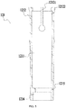
- the connecting rod 11 is an inactive connecting rod. An end of the connecting rod 11 facing toward the transmission groove 111 and an end of the connecting rod 11 facing toward the transmission shank 112 are fixedly connected, and the connecting rod 11 is formed with a stepped structure.
- the elastic portion 1212 is formed with a stopper 1214 that is fitted with the stepped structure to prevent the sleeve assembly 12 from disengaging from the connecting rod 11 along the central axis 101.
- the locking member 123 slides to the locking position along the central axis 101 while the elastic portion 1212 contracts inward with the central axis 101 as the center; under the action of the locking member 123, the stopper 1214 abuts against a surface of the connecting rod 11; and when the connecting rod 11 is subject to a force in a direction opposite to a first direction A or the sleeve body 121 is subject to a force parallel to the first direction A, the connecting rod 11 moves relative to the sleeve body 121 along the direction of the force.
- the stopper 1214 is clamped to the stepped structure of the connecting rod 11, thereby preventing the sleeve assembly 12 from disengaging from the connecting rod 11 along the central axis 101.
- the connecting rod 11 is inserted into the sleeve body 121 along the first direction A parallel to the central axis 101.
- the sleeve body 121 is also connected to or formed with a limiting portion 1215 that prevents the connecting rod 11 from continuing to move along the first direction A relative to the sleeve body 121, that is, during a process of the connecting rod 11 being inserted into the sleeve body 121 along the first direction A parallel to the central axis 101, the connecting rod 11 is blocked by the limiting portion 1215, thereby abutting against the limiting portion 1215.
- the limiting portion 1215 is an annular body arranged inside the sleeve body 121, the annular body is coaxial with and integrated with the sleeve body 121, and an inner diameter of the annular body is less than an outer diameter of the connecting rod 11, so as to prevent the connecting rod 11 from disengaging from the sleeve body 121 along the first direction A.
- the functional body 122 at least includes a magnetic portion capable of attracting the screwdriver bit.
- the functional body 122 includes a magnet, such as a ring magnet, capable of attracting the screwdriver bit.
- An end of the sleeve body 121 facing away from the elastic portion 1212 is further formed with an accommodation portion 1216 for accommodating the functional body 122, that is, the functional body 122 is located at an end of the sleeve main body 121 and the elastic portion 1212 is located at another end of the sleeve main body 121.
- the functional body 122 is embedded in the accommodation portion 1216, and is coaxially and fixedly connected to the sleeve body 121, and an end surface of the functional body 122 and an end surface of the sleeve body 121 are on a same plane.
- a connection form of the functional body 122 and the accommodation portion 1216 is not limited to a fixed connection, and is not limited to the above-mentioned mosaic structure.
- the functional body 122 may attract the screw so that the screw does not shake or disengage relative to the screwdriver bit, so as to realize the nail-holding effect, enabling an operator to complete work with only one hand, without holding the screw with one hand and operating the connecting rod 11 with another hand.
- the structural form of the magnetic portion is not limited to the single integral circular ring magnet structure in the present embodiment, but may also be other integral or split structures that are symmetrical relative to the central axis.
- Part of the connecting rod 11 is located inside the sleeve body 121, and the connecting rod 11 at least has a first position and a second position relative to the sleeve assembly 12 along the central axis 101.
- the connecting rod 11 When the connecting rod 11 is in the first position relative to the sleeve assembly 12, an end of the connecting rod 11 abuts against the limiting portion 1215; and when the connecting rod 11 is in the second position relative to the sleeve assembly 12, the connecting rod 11 is disengaged from the limiting portion 1215.
- the magnetic portion generates a magnetic force that may drive the connecting rod 11 to move toward the first position.
- the functional body 122 generates the magnetic force that drives the connecting rod 11 to move toward the first position; when there is no external axial force along the central axis 101, the connecting rod 11 keeps in the first position relative to the sleeve assembly 12, that is, an end of the connecting rod 11 facing toward the transmission groove 111 is in contact with the limiting portion 1215 and is maintained at the contact position; when the connecting rod 11 is subjected to an external force that is greater than the second axial force and less than the first axial force and is opposite to the first direction A, the connecting rod 11 is disengaged from the limiting portion 1215.
- the connecting rod 11 may be disengaged from the sleeve assembly 12 under the external force; and if the locking member 123 is in the locking position, the connecting rod 11 moves farthest to the second position relative to the sleeve assembly 12 under the action of the external force but cannot be disengaged from the sleeve assembly 12.
- the connecting rod 11 may move relative to the sleeve assembly 12 to any position between the first position and the second position under the external force.
- the screwdriver bit at least has a connection position and a disengagement position relative to the connecting rod 11.
- the screwdriver bit When the screwdriver bit is in the connection position, the screwdriver bit is accommodated in the transmission slot 111 and abuts against the connecting rod 11; and when the screwdriver bit is in the disengagement position, the screwdriver bit is disengaged from the connecting rod 11.
- the connecting rod 11 generates the magnetic force that may drive the screwdriver bit to move toward the connection position, that is to say, the connecting rod 11 is made of a magnetic material capable of attracting the screwdriver bit, so that the connecting rod 11 always has a magnetic attraction to the screwdriver bit, so that the screwdriver bit may be tightly mounted to the connecting rod 11.
- the screwdriver bit may overcome the magnetic attraction to move to the disengagement position under the action of external force.
- part of the connecting rod 11 is made of the magnetic material.
- the transmission groove 111 is connected to or integrally formed with the magnetic material capable of attracting the screwdriver bit.
- the sleeve assembly 12 is formed with a stopping portion 124 for preventing the screwdriver bit from disengaging from the connecting rod 11, and a distance between the stopping portion 124 and the central axis 101 is less than 3 mm.
- the stopping portion 124 limits the screwdriver bit in the first direction A so that only part of the screwdriver bit may pass a screwdriver bit hole 124, preventing the screwdriver bit from disengaging from the connecting rod 11 and the sleeve assembly 12 from the first direction A.
- the locking member 123 prevents the screwdriver bit from disengaging from the connecting rod 11 and the sleeve assembly 12 from the direction opposite to the first direction A, thereby realizing the function of locking the screwdriver bit.
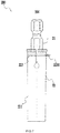
- FIG. 7 illustrates a connecting rod assembly 200 according to a second embodiment.
- the connecting rod assembly 200 may have a connecting rod 21 having the same structure as that of the second embodiment, except that the structures of the locking member 223 and the sleeve body 221 of the sleeve assembly 22 in the present embodiment are different.
- the portions of the first embodiment that are compatible with the present embodiment may be applied to the present embodiment. Only the differences between the present embodiment and the first embodiment will be described below.
- the sleeve assembly 22 includes the sleeve body 221, the magnetic portion (not shown in the figure), and a locking sleeve 223; where the locking sleeve 223 is fixedly connected to the sleeve body 221, and the locking sleeve 223 includes an adjusting portion 2231 that may extend relative to the sleeve body 221 in a plane perpendicular to the central axis 201 so as to adjust the tightness of the connection between the locking sleeve 223 and the sleeve body 221.
- the locking sleeve 223 has the locked state and the unlocked state relative to the sleeve body 221.
- connection manner between the locking sleeve 223 and the sleeve body 221 may also be a movable connection manner.
- the sleeve body 221 does not include the sliding groove 1213 and the similar movable connection structure in the first embodiment, but it can be understood that in the present embodiment, the locking sleeve 223 and the sleeve body 221 may also form a movable connection, and the sleeve body 221 may also form a limit structure for the locking sleeve 223.
- the locking member may also be other structural members having the locking function, and the connection manner between the sleeve body and the locking member is also not limited to the preferred modes in the above-mentioned two embodiments.
- the present disclosure provides a connecting rod assembly for a screwdriver bit, so that a sleeve of the connecting rod assembly is detachable and the connecting rod assembly has a function of locking a screwdriver bit.
Landscapes
- Engineering & Computer Science (AREA)
- Mechanical Engineering (AREA)
- Mutual Connection Of Rods And Tubes (AREA)
- Details Of Spanners, Wrenches, And Screw Drivers And Accessories (AREA)
- Toys (AREA)
Applications Claiming Priority (2)
| Application Number | Priority Date | Filing Date | Title |
|---|---|---|---|
| CN201820542835.3U CN208262717U (zh) | 2018-04-16 | 2018-04-16 | 适用于批头的接杆组件以及适用于接杆的套筒组件 |
| PCT/CN2019/079986 WO2019201069A1 (zh) | 2018-04-16 | 2019-03-28 | 用于批头的接杆组件以及适用于接杆的套筒组件 |
Publications (2)
| Publication Number | Publication Date |
|---|---|
| EP3753677A1 true EP3753677A1 (de) | 2020-12-23 |
| EP3753677A4 EP3753677A4 (de) | 2021-05-19 |
Family
ID=64677416
Family Applications (1)
| Application Number | Title | Priority Date | Filing Date |
|---|---|---|---|
| EP19787757.4A Withdrawn EP3753677A4 (de) | 2018-04-16 | 2019-03-28 | Verbindungsgestänge für schraubbohrmeissel und an eine pleuelstange angepasste hülsenanordnung |
Country Status (4)
| Country | Link |
|---|---|
| US (1) | US20200290185A1 (de) |
| EP (1) | EP3753677A4 (de) |
| CN (1) | CN208262717U (de) |
| WO (1) | WO2019201069A1 (de) |
Families Citing this family (5)
| Publication number | Priority date | Publication date | Assignee | Title |
|---|---|---|---|---|
| CN208262717U (zh) * | 2018-04-16 | 2018-12-21 | 南京德朔实业有限公司 | 适用于批头的接杆组件以及适用于接杆的套筒组件 |
| CN112809598B (zh) * | 2019-11-15 | 2023-10-13 | 汉达精密电子(昆山)有限公司 | 一种套筒结构 |
| CN115205502B (zh) * | 2022-09-16 | 2022-12-27 | 杭州申昊科技股份有限公司 | 刀闸操作方法及装置、电子设备 |
| TWI840190B (zh) * | 2023-04-12 | 2024-04-21 | 薪螢企業有限公司 | 磁力驅動裝置 |
| TWI907203B (zh) * | 2024-12-11 | 2025-12-01 | 薪螢企業有限公司 | 夾頭接桿 |
Family Cites Families (10)
| Publication number | Priority date | Publication date | Assignee | Title |
|---|---|---|---|---|
| KR880004381Y1 (ko) * | 1985-07-05 | 1988-12-12 | 김사현 | 도라이바 |
| US20080184853A1 (en) * | 2007-02-06 | 2008-08-07 | Shiou-E Chen | Screw Positioning Sleeve Assembly |
| US20080216618A1 (en) * | 2007-02-06 | 2008-09-11 | Shiou-E Chen | Screw Positioning Sleeve Assembly |
| US8070377B2 (en) * | 2008-03-07 | 2011-12-06 | Tzu-Chien Wang | Quick-release coupler |
| CN101745885A (zh) * | 2008-12-02 | 2010-06-23 | 谢智庆 | 卡扣及释放套筒的连接装置 |
| US9156147B2 (en) * | 2012-02-15 | 2015-10-13 | Black & Decker Inc. | Quick change bit holder with ring magnet |
| CN202943564U (zh) * | 2012-12-04 | 2013-05-22 | 上海索尔装饰成套制品有限公司 | 装配工具 |
| CN204171940U (zh) * | 2014-07-15 | 2015-02-25 | 南京德朔实业有限公司 | 适用于批头的配件及具有该配件的批头组件 |
| TW201702022A (zh) * | 2015-07-15 | 2017-01-16 | Hong Ann Tool Industries Co Ltd | 工具接桿 |
| CN208262717U (zh) * | 2018-04-16 | 2018-12-21 | 南京德朔实业有限公司 | 适用于批头的接杆组件以及适用于接杆的套筒组件 |
-
2018
- 2018-04-16 CN CN201820542835.3U patent/CN208262717U/zh not_active Expired - Fee Related
-
2019
- 2019-03-28 WO PCT/CN2019/079986 patent/WO2019201069A1/zh not_active Ceased
- 2019-03-28 EP EP19787757.4A patent/EP3753677A4/de not_active Withdrawn
-
2020
- 2020-06-02 US US16/889,927 patent/US20200290185A1/en not_active Abandoned
Also Published As
| Publication number | Publication date |
|---|---|
| CN208262717U (zh) | 2018-12-21 |
| US20200290185A1 (en) | 2020-09-17 |
| WO2019201069A1 (zh) | 2019-10-24 |
| EP3753677A4 (de) | 2021-05-19 |
Similar Documents
| Publication | Publication Date | Title |
|---|---|---|
| EP3753677A1 (de) | Verbindungsgestänge für schraubbohrmeissel und an eine pleuelstange angepasste hülsenanordnung | |
| AU2021254603B2 (en) | Connection structure of operation rod | |
| EP1967326B1 (de) | Vorrichtungen zur Montage eines Bohrmeißels | |
| USRE47515E1 (en) | Rotary shaver with improved support structure for shaving heads | |
| US9233424B2 (en) | Adapter for holding a hole saw on a power tool | |
| EP3366424B1 (de) | Schnell lösbarer und einstellbarer magnetischer sitz für eine hülse | |
| EP3352946B1 (de) | Befestigungspatrone | |
| US20150107865A1 (en) | Auxiliary handle and electric tool having the same | |
| JPH03503990A (ja) | 構成部品を適宣のキャリア部材に取外し可能に固定する連結器 | |
| CN111163888B (zh) | 具有抗振特征的锁定夹头 | |
| CN110382147B (zh) | 卡盘机构 | |
| JP6033823B2 (ja) | 継手及びこれに装着する一組の分割カラー | |
| CN213906540U (zh) | 直连安装的电机快换结构 | |
| CN112542917B (zh) | 直连安装的电机快换结构 | |
| CN213906485U (zh) | 直连安装的电机快换结构 | |
| CN112510963B (zh) | 直连安装的电机快换结构 | |
| CN109202798B (zh) | 螺丝刀 | |
| CN214367123U (zh) | 快速锁紧销 | |
| CN108237498B (zh) | 夹头 | |
| WO2024234217A1 (en) | Chuck with quick connect spindle interface | |
| US20260124683A1 (en) | Chuck with quick connect spindle interface | |
| US20230216368A1 (en) | Drive unit | |
| EP3764193B1 (de) | Griffvorrichtung und stanzmaschine | |
| CN111278590B (zh) | 一种与具有可旋转驱动轴的动力驱动器一起使用的夹头 | |
| KR20250031953A (ko) | 양용 슬리브 |
Legal Events
| Date | Code | Title | Description |
|---|---|---|---|
| STAA | Information on the status of an ep patent application or granted ep patent |
Free format text: STATUS: THE INTERNATIONAL PUBLICATION HAS BEEN MADE |
|
| PUAI | Public reference made under article 153(3) epc to a published international application that has entered the european phase |
Free format text: ORIGINAL CODE: 0009012 |
|
| STAA | Information on the status of an ep patent application or granted ep patent |
Free format text: STATUS: REQUEST FOR EXAMINATION WAS MADE |
|
| 17P | Request for examination filed |
Effective date: 20200602 |
|
| AK | Designated contracting states |
Kind code of ref document: A1 Designated state(s): AL AT BE BG CH CY CZ DE DK EE ES FI FR GB GR HR HU IE IS IT LI LT LU LV MC MK MT NL NO PL PT RO RS SE SI SK SM TR |
|
| AX | Request for extension of the european patent |
Extension state: BA ME |
|
| A4 | Supplementary search report drawn up and despatched |
Effective date: 20210421 |
|
| RIC1 | Information provided on ipc code assigned before grant |
Ipc: B25B 23/00 20060101AFI20210415BHEP Ipc: B25B 23/12 20060101ALI20210415BHEP |
|
| DAV | Request for validation of the european patent (deleted) | ||
| DAX | Request for extension of the european patent (deleted) | ||
| STAA | Information on the status of an ep patent application or granted ep patent |
Free format text: STATUS: THE APPLICATION HAS BEEN WITHDRAWN |
|
| 18W | Application withdrawn |
Effective date: 20210923 |