EP3754818B1 - Carcasse d'une machine électrique - Google Patents
Carcasse d'une machine électrique Download PDFInfo
- Publication number
- EP3754818B1 EP3754818B1 EP19181405.2A EP19181405A EP3754818B1 EP 3754818 B1 EP3754818 B1 EP 3754818B1 EP 19181405 A EP19181405 A EP 19181405A EP 3754818 B1 EP3754818 B1 EP 3754818B1
- Authority
- EP
- European Patent Office
- Prior art keywords
- frame
- electric machine
- modules
- axial
- iec
- Prior art date
- Legal status (The legal status is an assumption and is not a legal conclusion. Google has not performed a legal analysis and makes no representation as to the accuracy of the status listed.)
- Active
Links
Images
Classifications
-
- H—ELECTRICITY
- H02—GENERATION; CONVERSION OR DISTRIBUTION OF ELECTRIC POWER
- H02K—DYNAMO-ELECTRIC MACHINES
- H02K15/00—Processes or apparatus specially adapted for manufacturing, assembling, maintaining or repairing of dynamo-electric machines
- H02K15/14—Casings; Enclosures; Supports
-
- H—ELECTRICITY
- H02—GENERATION; CONVERSION OR DISTRIBUTION OF ELECTRIC POWER
- H02K—DYNAMO-ELECTRIC MACHINES
- H02K5/00—Casings; Enclosures; Supports
- H02K5/04—Casings or enclosures characterised by the shape, form or construction thereof
- H02K5/20—Casings or enclosures characterised by the shape, form or construction thereof with channels or ducts for flow of cooling medium
- H02K5/203—Casings or enclosures characterised by the shape, form or construction thereof with channels or ducts for flow of cooling medium specially adapted for liquids, e.g. cooling jackets
-
- H—ELECTRICITY
- H02—GENERATION; CONVERSION OR DISTRIBUTION OF ELECTRIC POWER
- H02K—DYNAMO-ELECTRIC MACHINES
- H02K2213/00—Specific aspects, not otherwise provided for and not covered by codes H02K2201/00 - H02K2211/00
- H02K2213/03—Machines characterised by numerical values, ranges, mathematical expressions or similar information
-
- H—ELECTRICITY
- H02—GENERATION; CONVERSION OR DISTRIBUTION OF ELECTRIC POWER
- H02K—DYNAMO-ELECTRIC MACHINES
- H02K2213/00—Specific aspects, not otherwise provided for and not covered by codes H02K2201/00 - H02K2211/00
- H02K2213/12—Machines characterised by the modularity of some components
-
- H—ELECTRICITY
- H02—GENERATION; CONVERSION OR DISTRIBUTION OF ELECTRIC POWER
- H02K—DYNAMO-ELECTRIC MACHINES
- H02K9/00—Arrangements for cooling or ventilating
Definitions
- the invention relates to a frame of an electric machine.
- Electric machines i.e. electric motors and electric generators are used in many applications. Electric motors are used to drive different kinds of machines and electric generators are used to produce electric power.
- An electric machine may comprise a rotating shaft, a rotor on the shaft, a stationary stator and a frame.
- the rotor may be provided with a rotor winding e.g. a squirrel cage or with permanent magnets.
- the stator may comprise a stator core with a stator winding.
- the shaft may be supported via bearings on end plates, said end plates being attached to the frame.
- the electric machine may be cooled with liquid e.g. water passing in cooling ducts in the frame.
- liquid e.g. water passing in cooling ducts in the frame.
- Water cooled frames have traditionally been manufactured by casting or by using a welded construction. Steel tubes have been embedded in the casting to provide a flow channel for the cooling media. These manufacturing methods might not be the most cost effective especially for smaller electric machines. This is due to the high amount of manual work and/or the high tooling costs. This applies e.g. to electric machines being smaller than IEC 250 i.e. a standard prepared by the International Electrotechnical Commission (IEC) for the frame size of electric machines. The electric machine is in this standard standardized in view of essential parameters of the electric machine.
- IEC 250 i.e. a standard prepared by the International Electrotechnical Commission (IEC) for the frame size of electric machines.
- IEC International Electrotechnical Commission
- the frame could be made e.g. from an extruded tubular profile with integrated water cooling channels, whereby the problem of investing in a new tool for different lengths of the electric machine would be solved. This is due to the fact that the extruded tubular profile may be cut to any desired length. The tooling costs for each separate inner diameter would, however, still remain.
- US 2010/0007227 discloses a cooling jacket for a drive motor.
- the cooling jacket includes an extruded jacket body having an outer peripheral surface, an inner peripheral surface, and a plurality of discrete cooling passages located between the inner and the outer peripheral surfaces that provided multi-directional fluid flow.
- a fluid inlet is provided to direct cooling fluid into the jacket body and a fluid outlet to direct heated fluid awai from the jacket body.
- An object of the present invention is to achieve an improved frame of an electric machine.
- the method comprises
- the invention makes it possible to use one simple inexpensive extrusion tool in order to manufacture the frame module with the at least one axial cooling duct.
- the use of the frame module makes it possible to manufacture a frame of a desired length and with a desired diameter.
- the frame module or the complete frame comprising several frame modules may easily be cut to a desired length.
- a desired frame in accordance with the corresponding IEC standard may easily be achieved by varying the number of frame modules used in the frame.
- the electric machine may be a liquid cooled electric machine.
- the liquid may be e.g. water or oil.
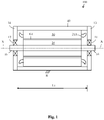
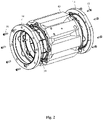
- Fig. 1 shows a side view of an electric machine and figure 2 shows an axonometric view of an electric machine.
- the electric machine 100 may comprise a longitudinal centre axis X-X, a shaft 10, a rotor 20 attached to a centre portion of the shaft 10, a stator 30 surrounding the rotor 20, and a frame 40 surrounding the stator 30.
- the rotor 20 and the stator 30 may be cylindrical.
- Each end of the shaft 10 may be rotatably supported on a bearing 11, 12.
- Each bearing 11, 12 may be supported in a bearing house in a respective end plate 13, 14 of the electric machine 100.
- the end plates 13, 14 may be attached to a respective end of the frame 40.
- the rotor 20 may be provided with a rotor winding (not shown in the figure).
- the stator 30 may comprise a stator core surrounding the rotor 20.
- the stator 30 core may be provided with a stator winding. The figure shows only the winding ends 21A of the stator winding.
- the frame 40 may be supported on a support structure R at the installation site of the electric machine 100.
- the frame 40 may be supported on the support structure R through support feet attached to the outer surface of the frame 40 or through support feet attached to the end plates 13, 14.
- the support feet may be attached e.g. by welding to the frame 40 or to the end plates 13, 14.
- the frame 40 may be attached to the stator 30 with a press-on fit.
- the frame 40 has an axial length L1.
- the frame 40 may be made of a material suitable to be welded. Suitable materials are e.g. steel and aluminium.
- the end plates 13, 14 may be attached with fastening means 15, 16 e.g. screws to the frame 40.
- the screws 15, 16 may extend in the axial X-X direction through the end plates 13, 14 to the end of the frame 40.
- the electric machine 100 can be an electric motor or an electric generator.
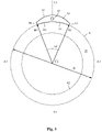
- Fig. 3 shows a transverse cross section of a frame of the electric machine.
- the outer broken line A1 in the figure represents the outer circumference of the stator core 30 in the electric machine.
- the inner broken line A2 in the figure represents the inner circumference of the stator core 30 in the electric machine.
- the outer circumference A1 of the stator core 30 corresponds to the inner circumference of the frame 40 of the electric machine.
- the figure shows only one frame module 50 of the frame 40.
- the inner diameter D of the frame 40 is indicated in the figure.
- the frame module 50 comprises an inner surface 51 forming an arc coinciding with the inner circumference A1 of the frame 40, an outer surface 52, and two side edges 53, 54 extending between the ends of the inner surface 51 and the outer surface 52.
- the side edges 53, 54 of the frame module 50 may extend in a radial direction outwards from the circumference A1 of the frame 40.
- the side edges 53, 54 of the frame module 50 may on the other hand extend in an axial direction X-X along the axial length L1 of the frame 40.
- the frame module 50 may further comprise at least one axial cooling duct 55 passing through the frame module 50 in the axial direction.
- the axial cooling duct 55 may be a liquid e.g. water cooling duct.
- the outer surface 52 of the frame module 50 may have any suitable form.
- the outer surface 52 of the frame module 50 may be formed of smooth curves or of angular curves or of a combination of these.
- the inner surface 51 of the frame module 50 may be seated against the outer surface of the stator 30.
- the frame module 50 may be manufactured by extrusion. Extrusion allows for a free adjustment of the axial length of the frame module 50.
- the frame 40 comprises in this embodiment eight identical frame modules 50. Adjacent frame modules 50 may be attached to each other by welding the opposite side edges 53, 54 of the frame modules 50 together along the axial length of the side edges 53, 54 of the frame modules 50. A uniform frame 40 may thus be formed of several frame modules 50.
- An angle ⁇ 1 between a first radius R1 extending from a centre C1 of the inner circumference A1 of the frame 40 to a first side edge 53 of the frame module 50 and a second radius R2 extending from the centre C1 of the inner circumference A1 of the frame 40 to a second side edge 54 of the frame module 50 is thus 45 degrees.
- the centre C1 of the frame 40 coincides with the centre of the electric machine.
- the centre of the frame 40 is situated on the longitudinal centre axis X-X of the electric machine.
- the figure shows also a horizontal centre line X1-X1 of the cross section of the frame 40 and a vertical centre line Y1-Y1 of the cross section of the frame 40.
- the inner diameters of frames 40 for electric machines according to the International Electrotechnical Commission (IEC) frame size standard form nearly an arithmetic series.
- the frame 40 is manufactured from frame modules 50 so that 8 modules 50 are used for IEC frame 160, 9 modules 50 for IEC frame 180 and 10 modules for IEC 200.
- the arc length of the inner surface 51 of one module 50 in the frame 40 when N modules are used to form the frame 40 is thus ⁇ * 20 [mm].
- the frame modules 50 are welded together along the axially extending side edges 53, 54 of the frame modules 50.
- the curvature of the inner surface 51 of the arc-shaped frame modules 50 will not initially match the circumference of the stator opening. Machining allowance may therefore be added to the profile of the frame module 50.
- the welded frame 40 is then finally machined in order to achieve a desired circular inner opening of the frame 40.
- the axial cooling ducts 55 may be connected together at each end of the frame 40. This may be done by machining grooves in a circumferential direction between adjacent cooling ducts 55 at the ends of the frame 40. Another possibility would be to attach an end flange to each end surface of the frame 40.
- the end flange could comprise a circumferential cooling fluid groove machined into the end surface of the end flange that will seat against the end of the frame 40.
- the circumferential centre line of the cooling fluid groove in the end frame may correspond to the circumferential centre line connecting the centres of the axial ducts 55 at the end of the frame 40.
- the fluid inlet passage and the fluid outlet passage could on the other hand be arranged through a frame module 50.
- a radial bore could extend from the outer surface of the frame module 50 to the end of the axial inlet fluid duct.
- a coupling piece could be screwed into the radial bore forming a connection for the inlet for cooling fluid to the machine.
- a radial bore could extend from the outer surface of the frame module 50 to the end of the axial outlet fluid duct.
- a coupling piece could be screwed into the radial bore forming a connection for the outlet for cooling fluid from the machine.
- the frame of the electric machine is produced by a method comprising
- the electric machine may be a liquid cooled electric machine.
- the liquid may be e.g. water or oil.
Landscapes
- Engineering & Computer Science (AREA)
- Power Engineering (AREA)
- Manufacturing & Machinery (AREA)
- Motor Or Generator Frames (AREA)
- Motor Or Generator Cooling System (AREA)
Claims (6)
- Procédé de production d'une carcasse d'une machine électrique, le procédé comprenant :la production de modules de carcasse (50) ayant une surface interne en forme d'arc (51), les modules de carcasse (50) s'étendant dans la direction axiale (X-X) sur une longueur (L1) de la carcasse (40) et dans la direction circonférentielle (A) sur une partie de la circonférence de la carcasse (40), chaque module de carcasse (50) comprenant au moins un conduit de refroidissement coaxial (55) passant dans la direction axiale à travers le module de carcasse (50),la détermination du numéro de carcasse IEC à produire,la détermination de N, dans lequel N = 8 pour une taille de carcasse IEC de 160, N = 9 pour une taille de carcasse IEC de 180 et N = 10 pour une taille de carcasse IEC de 200, etc.,le positionnement de N modules de carcasse identiques (50) adjacents les uns aux autres de façon que la surface interne en forme d'arc (51) des modules de carcasse (50) soit assise sur une circonférence interne (A1) de la carcasse (40),le soudage de modules de carcasse adjacents (50) les uns aux autres à partir des bords (53, 54) des modules de carcasse (50) par le soudage conjoint des bords latéraux opposés (53, 54), dans la direction circonférentielle, de modules de carcasse adjacents (50) le long de la direction axiale des bords latéraux (53, 54) des modules de carcasse (50) afin de former une carcasse circulaire continue (40),l'usinage d'une surface interne de la carcasse (40) afin d'obtenir une ouverture interne circulaire d'un diamètre souhaité dans la carcasse (40),dans lequel un diamètre interne de la carcasse (40) est déterminé selon l'équation suivante D = 20*N mm et dans lequel une longueur d'arc (A1) de la surface interne en forme d'arc (51) des modules de carcasse (50) est égale à n*20 mm.
- Carcasse pour une machine électrique fabriquée selon le procédé de la revendication 1.
- Carcasse selon la revendication 2, dans laquelle les conduits de refroidissement axiaux (55) sont reliés à chaque extrémité axiale (X-X) de la carcasse (40) par une rainure circonférentielle à l'extrémité axiale (X-X) de la carcasse (40).
- Machine électrique comprenant une carcasse (40) selon l'une quelconque des revendications 2 à 3.
- Machine électrique selon la revendication 4, dans laquelle la machine électrique comprend un rotor (20) et un stator (30) entourant le rotor (20), la carcasse entourant le stator (30).
- Machine électrique selon la revendication 5, dans laquelle le rotor (20) et le stator (30) ont une forme cylindrique.
Priority Applications (2)
| Application Number | Priority Date | Filing Date | Title |
|---|---|---|---|
| EP19181405.2A EP3754818B1 (fr) | 2019-06-20 | 2019-06-20 | Carcasse d'une machine électrique |
| PCT/EP2020/066713 WO2020254374A1 (fr) | 2019-06-20 | 2020-06-17 | Cadre de machine électrique |
Applications Claiming Priority (1)
| Application Number | Priority Date | Filing Date | Title |
|---|---|---|---|
| EP19181405.2A EP3754818B1 (fr) | 2019-06-20 | 2019-06-20 | Carcasse d'une machine électrique |
Publications (2)
| Publication Number | Publication Date |
|---|---|
| EP3754818A1 EP3754818A1 (fr) | 2020-12-23 |
| EP3754818B1 true EP3754818B1 (fr) | 2022-08-24 |
Family
ID=66999685
Family Applications (1)
| Application Number | Title | Priority Date | Filing Date |
|---|---|---|---|
| EP19181405.2A Active EP3754818B1 (fr) | 2019-06-20 | 2019-06-20 | Carcasse d'une machine électrique |
Country Status (2)
| Country | Link |
|---|---|
| EP (1) | EP3754818B1 (fr) |
| WO (1) | WO2020254374A1 (fr) |
Family Cites Families (1)
| Publication number | Priority date | Publication date | Assignee | Title |
|---|---|---|---|---|
| US8161643B2 (en) * | 2007-09-20 | 2012-04-24 | Arvinmeritor Technology, Llc | Method for forming a cooling jacket for an electric motor |
-
2019
- 2019-06-20 EP EP19181405.2A patent/EP3754818B1/fr active Active
-
2020
- 2020-06-17 WO PCT/EP2020/066713 patent/WO2020254374A1/fr not_active Ceased
Also Published As
| Publication number | Publication date |
|---|---|
| WO2020254374A1 (fr) | 2020-12-24 |
| WO2020254374A8 (fr) | 2021-02-25 |
| EP3754818A1 (fr) | 2020-12-23 |
Similar Documents
| Publication | Publication Date | Title |
|---|---|---|
| US8183723B2 (en) | Cooling jacket and stator assembly for rotary electric device | |
| US7626292B2 (en) | Cast groove electric motor/generator cooling mechanism | |
| US8067865B2 (en) | Electric motor/generator low hydraulic resistance cooling mechanism | |
| EP1953897A2 (fr) | Chemise de refroidissement pour moteur électrique | |
| HK1255433A1 (zh) | 用於电机的铸造冷却装置 | |
| US12088149B2 (en) | Cooling system for an electric machine | |
| US12034336B2 (en) | Cooling system for an electric machine having a wound field rotor | |
| US5592039A (en) | AC and DC motor-generator set having stators with annular end plate water cooling channels | |
| JP6730233B2 (ja) | 回転子、回転電機及び回転子の製造方法 | |
| DE102005002897B4 (de) | Flüssigkeitsgekühlte elektrische Maschine mit Gussgehäuse | |
| EP3754818B1 (fr) | Carcasse d'une machine électrique | |
| CN107925313B (zh) | 压缩机 | |
| EP3900160A1 (fr) | Moteur électrique doté d'une partie boîtier de stator | |
| JPH0522901A (ja) | 電動機の液冷手段とその製造方法 | |
| EP1484518B1 (fr) | Dispositif de lubrification de paliers de moteur électrique | |
| EP0918936B1 (fr) | Dispositif d'entrainement, tel qu'une machine a anneau liquide, et procede d'entrainement associe, tel qu'un transfert de fluide | |
| CN114123630A (zh) | 电主轴轴芯、电主轴及电机 | |
| DE19828406A1 (de) | Elektromotor | |
| EP3070816B1 (fr) | Procédé et dispositif pour refroidir une machine électrique | |
| US20230268797A1 (en) | Cooling jacket for electric motor having configuration for reducing electromagnetic noise | |
| JPS61170254A (ja) | 液冷モ−タ | |
| EP2920867B1 (fr) | Moteur électrique doté d'un stator | |
| CN110732689A (zh) | 一种加工中心用高精度运转电主轴 | |
| EP4687269A1 (fr) | Système de refroidissement pour stators de machines électriques tournantes, procédé de fabrication d'une plaque de refroidissement et machine électrique tournante correspondante | |
| CN215805217U (zh) | 一种带大推力水润滑轴承结构的叶轮内置式潜水贯流泵 |
Legal Events
| Date | Code | Title | Description |
|---|---|---|---|
| PUAI | Public reference made under article 153(3) epc to a published international application that has entered the european phase |
Free format text: ORIGINAL CODE: 0009012 |
|
| STAA | Information on the status of an ep patent application or granted ep patent |
Free format text: STATUS: THE APPLICATION HAS BEEN PUBLISHED |
|
| AK | Designated contracting states |
Kind code of ref document: A1 Designated state(s): AL AT BE BG CH CY CZ DE DK EE ES FI FR GB GR HR HU IE IS IT LI LT LU LV MC MK MT NL NO PL PT RO RS SE SI SK SM TR |
|
| AX | Request for extension of the european patent |
Extension state: BA ME |
|
| STAA | Information on the status of an ep patent application or granted ep patent |
Free format text: STATUS: REQUEST FOR EXAMINATION WAS MADE |
|
| STAA | Information on the status of an ep patent application or granted ep patent |
Free format text: STATUS: EXAMINATION IS IN PROGRESS |
|
| 17P | Request for examination filed |
Effective date: 20210525 |
|
| RBV | Designated contracting states (corrected) |
Designated state(s): AL AT BE BG CH CY CZ DE DK EE ES FI FR GB GR HR HU IE IS IT LI LT LU LV MC MK MT NL NO PL PT RO RS SE SI SK SM TR |
|
| 17Q | First examination report despatched |
Effective date: 20210629 |
|
| RIC1 | Information provided on ipc code assigned before grant |
Ipc: H02K 9/00 20060101ALN20220203BHEP Ipc: H02K 15/14 20060101ALI20220203BHEP Ipc: H02K 5/20 20060101AFI20220203BHEP |
|
| RIC1 | Information provided on ipc code assigned before grant |
Ipc: H02K 9/00 20060101ALN20220217BHEP Ipc: H02K 15/14 20060101ALI20220217BHEP Ipc: H02K 5/20 20060101AFI20220217BHEP |
|
| GRAP | Despatch of communication of intention to grant a patent |
Free format text: ORIGINAL CODE: EPIDOSNIGR1 |
|
| STAA | Information on the status of an ep patent application or granted ep patent |
Free format text: STATUS: GRANT OF PATENT IS INTENDED |
|
| RIC1 | Information provided on ipc code assigned before grant |
Ipc: H02K 9/00 20060101ALN20220221BHEP Ipc: H02K 15/14 20060101ALI20220221BHEP Ipc: H02K 5/20 20060101AFI20220221BHEP |
|
| RIC1 | Information provided on ipc code assigned before grant |
Ipc: H02K 9/00 20060101ALN20220301BHEP Ipc: H02K 15/14 20060101ALI20220301BHEP Ipc: H02K 5/20 20060101AFI20220301BHEP |
|
| INTG | Intention to grant announced |
Effective date: 20220328 |
|
| RAP3 | Party data changed (applicant data changed or rights of an application transferred) |
Owner name: ABB SCHWEIZ AG |
|
| GRAS | Grant fee paid |
Free format text: ORIGINAL CODE: EPIDOSNIGR3 |
|
| GRAA | (expected) grant |
Free format text: ORIGINAL CODE: 0009210 |
|
| STAA | Information on the status of an ep patent application or granted ep patent |
Free format text: STATUS: THE PATENT HAS BEEN GRANTED |
|
| AK | Designated contracting states |
Kind code of ref document: B1 Designated state(s): AL AT BE BG CH CY CZ DE DK EE ES FI FR GB GR HR HU IE IS IT LI LT LU LV MC MK MT NL NO PL PT RO RS SE SI SK SM TR |
|
| REG | Reference to a national code |
Ref country code: CH Ref legal event code: EP |
|
| REG | Reference to a national code |
Ref country code: DE Ref legal event code: R096 Ref document number: 602019018559 Country of ref document: DE |
|
| REG | Reference to a national code |
Ref country code: IE Ref legal event code: FG4D |
|
| REG | Reference to a national code |
Ref country code: AT Ref legal event code: REF Ref document number: 1514351 Country of ref document: AT Kind code of ref document: T Effective date: 20220915 |
|
| REG | Reference to a national code |
Ref country code: LT Ref legal event code: MG9D |
|
| REG | Reference to a national code |
Ref country code: NL Ref legal event code: MP Effective date: 20220824 |
|
| PG25 | Lapsed in a contracting state [announced via postgrant information from national office to epo] |
Ref country code: SE Free format text: LAPSE BECAUSE OF FAILURE TO SUBMIT A TRANSLATION OF THE DESCRIPTION OR TO PAY THE FEE WITHIN THE PRESCRIBED TIME-LIMIT Effective date: 20220824 Ref country code: RS Free format text: LAPSE BECAUSE OF FAILURE TO SUBMIT A TRANSLATION OF THE DESCRIPTION OR TO PAY THE FEE WITHIN THE PRESCRIBED TIME-LIMIT Effective date: 20220824 Ref country code: PT Free format text: LAPSE BECAUSE OF FAILURE TO SUBMIT A TRANSLATION OF THE DESCRIPTION OR TO PAY THE FEE WITHIN THE PRESCRIBED TIME-LIMIT Effective date: 20221226 Ref country code: NO Free format text: LAPSE BECAUSE OF FAILURE TO SUBMIT A TRANSLATION OF THE DESCRIPTION OR TO PAY THE FEE WITHIN THE PRESCRIBED TIME-LIMIT Effective date: 20221124 Ref country code: NL Free format text: LAPSE BECAUSE OF FAILURE TO SUBMIT A TRANSLATION OF THE DESCRIPTION OR TO PAY THE FEE WITHIN THE PRESCRIBED TIME-LIMIT Effective date: 20220824 Ref country code: LV Free format text: LAPSE BECAUSE OF FAILURE TO SUBMIT A TRANSLATION OF THE DESCRIPTION OR TO PAY THE FEE WITHIN THE PRESCRIBED TIME-LIMIT Effective date: 20220824 Ref country code: LT Free format text: LAPSE BECAUSE OF FAILURE TO SUBMIT A TRANSLATION OF THE DESCRIPTION OR TO PAY THE FEE WITHIN THE PRESCRIBED TIME-LIMIT Effective date: 20220824 Ref country code: FI Free format text: LAPSE BECAUSE OF FAILURE TO SUBMIT A TRANSLATION OF THE DESCRIPTION OR TO PAY THE FEE WITHIN THE PRESCRIBED TIME-LIMIT Effective date: 20220824 |
|
| REG | Reference to a national code |
Ref country code: AT Ref legal event code: MK05 Ref document number: 1514351 Country of ref document: AT Kind code of ref document: T Effective date: 20220824 |
|
| PG25 | Lapsed in a contracting state [announced via postgrant information from national office to epo] |
Ref country code: PL Free format text: LAPSE BECAUSE OF FAILURE TO SUBMIT A TRANSLATION OF THE DESCRIPTION OR TO PAY THE FEE WITHIN THE PRESCRIBED TIME-LIMIT Effective date: 20220824 Ref country code: IS Free format text: LAPSE BECAUSE OF FAILURE TO SUBMIT A TRANSLATION OF THE DESCRIPTION OR TO PAY THE FEE WITHIN THE PRESCRIBED TIME-LIMIT Effective date: 20221224 Ref country code: HR Free format text: LAPSE BECAUSE OF FAILURE TO SUBMIT A TRANSLATION OF THE DESCRIPTION OR TO PAY THE FEE WITHIN THE PRESCRIBED TIME-LIMIT Effective date: 20220824 Ref country code: GR Free format text: LAPSE BECAUSE OF FAILURE TO SUBMIT A TRANSLATION OF THE DESCRIPTION OR TO PAY THE FEE WITHIN THE PRESCRIBED TIME-LIMIT Effective date: 20221125 |
|
| PG25 | Lapsed in a contracting state [announced via postgrant information from national office to epo] |
Ref country code: SM Free format text: LAPSE BECAUSE OF FAILURE TO SUBMIT A TRANSLATION OF THE DESCRIPTION OR TO PAY THE FEE WITHIN THE PRESCRIBED TIME-LIMIT Effective date: 20220824 Ref country code: RO Free format text: LAPSE BECAUSE OF FAILURE TO SUBMIT A TRANSLATION OF THE DESCRIPTION OR TO PAY THE FEE WITHIN THE PRESCRIBED TIME-LIMIT Effective date: 20220824 Ref country code: ES Free format text: LAPSE BECAUSE OF FAILURE TO SUBMIT A TRANSLATION OF THE DESCRIPTION OR TO PAY THE FEE WITHIN THE PRESCRIBED TIME-LIMIT Effective date: 20220824 Ref country code: DK Free format text: LAPSE BECAUSE OF FAILURE TO SUBMIT A TRANSLATION OF THE DESCRIPTION OR TO PAY THE FEE WITHIN THE PRESCRIBED TIME-LIMIT Effective date: 20220824 Ref country code: CZ Free format text: LAPSE BECAUSE OF FAILURE TO SUBMIT A TRANSLATION OF THE DESCRIPTION OR TO PAY THE FEE WITHIN THE PRESCRIBED TIME-LIMIT Effective date: 20220824 Ref country code: AT Free format text: LAPSE BECAUSE OF FAILURE TO SUBMIT A TRANSLATION OF THE DESCRIPTION OR TO PAY THE FEE WITHIN THE PRESCRIBED TIME-LIMIT Effective date: 20220824 |
|
| REG | Reference to a national code |
Ref country code: DE Ref legal event code: R097 Ref document number: 602019018559 Country of ref document: DE |
|
| PG25 | Lapsed in a contracting state [announced via postgrant information from national office to epo] |
Ref country code: SK Free format text: LAPSE BECAUSE OF FAILURE TO SUBMIT A TRANSLATION OF THE DESCRIPTION OR TO PAY THE FEE WITHIN THE PRESCRIBED TIME-LIMIT Effective date: 20220824 Ref country code: EE Free format text: LAPSE BECAUSE OF FAILURE TO SUBMIT A TRANSLATION OF THE DESCRIPTION OR TO PAY THE FEE WITHIN THE PRESCRIBED TIME-LIMIT Effective date: 20220824 |
|
| PG25 | Lapsed in a contracting state [announced via postgrant information from national office to epo] |
Ref country code: AL Free format text: LAPSE BECAUSE OF FAILURE TO SUBMIT A TRANSLATION OF THE DESCRIPTION OR TO PAY THE FEE WITHIN THE PRESCRIBED TIME-LIMIT Effective date: 20220824 |
|
| PLBE | No opposition filed within time limit |
Free format text: ORIGINAL CODE: 0009261 |
|
| STAA | Information on the status of an ep patent application or granted ep patent |
Free format text: STATUS: NO OPPOSITION FILED WITHIN TIME LIMIT |
|
| 26N | No opposition filed |
Effective date: 20230525 |
|
| PG25 | Lapsed in a contracting state [announced via postgrant information from national office to epo] |
Ref country code: SI Free format text: LAPSE BECAUSE OF FAILURE TO SUBMIT A TRANSLATION OF THE DESCRIPTION OR TO PAY THE FEE WITHIN THE PRESCRIBED TIME-LIMIT Effective date: 20220824 |
|
| PG25 | Lapsed in a contracting state [announced via postgrant information from national office to epo] |
Ref country code: MC Free format text: LAPSE BECAUSE OF FAILURE TO SUBMIT A TRANSLATION OF THE DESCRIPTION OR TO PAY THE FEE WITHIN THE PRESCRIBED TIME-LIMIT Effective date: 20220824 |
|
| PG25 | Lapsed in a contracting state [announced via postgrant information from national office to epo] |
Ref country code: MC Free format text: LAPSE BECAUSE OF FAILURE TO SUBMIT A TRANSLATION OF THE DESCRIPTION OR TO PAY THE FEE WITHIN THE PRESCRIBED TIME-LIMIT Effective date: 20220824 |
|
| REG | Reference to a national code |
Ref country code: CH Ref legal event code: PL |
|
| REG | Reference to a national code |
Ref country code: BE Ref legal event code: MM Effective date: 20230630 |
|
| PG25 | Lapsed in a contracting state [announced via postgrant information from national office to epo] |
Ref country code: LU Free format text: LAPSE BECAUSE OF NON-PAYMENT OF DUE FEES Effective date: 20230620 |
|
| REG | Reference to a national code |
Ref country code: IE Ref legal event code: MM4A |
|
| PG25 | Lapsed in a contracting state [announced via postgrant information from national office to epo] |
Ref country code: LU Free format text: LAPSE BECAUSE OF NON-PAYMENT OF DUE FEES Effective date: 20230620 |
|
| PG25 | Lapsed in a contracting state [announced via postgrant information from national office to epo] |
Ref country code: IE Free format text: LAPSE BECAUSE OF NON-PAYMENT OF DUE FEES Effective date: 20230620 |
|
| PG25 | Lapsed in a contracting state [announced via postgrant information from national office to epo] |
Ref country code: IE Free format text: LAPSE BECAUSE OF NON-PAYMENT OF DUE FEES Effective date: 20230620 Ref country code: CH Free format text: LAPSE BECAUSE OF NON-PAYMENT OF DUE FEES Effective date: 20230630 |
|
| PG25 | Lapsed in a contracting state [announced via postgrant information from national office to epo] |
Ref country code: IT Free format text: LAPSE BECAUSE OF FAILURE TO SUBMIT A TRANSLATION OF THE DESCRIPTION OR TO PAY THE FEE WITHIN THE PRESCRIBED TIME-LIMIT Effective date: 20220824 Ref country code: BE Free format text: LAPSE BECAUSE OF NON-PAYMENT OF DUE FEES Effective date: 20230630 |
|
| PG25 | Lapsed in a contracting state [announced via postgrant information from national office to epo] |
Ref country code: BG Free format text: LAPSE BECAUSE OF FAILURE TO SUBMIT A TRANSLATION OF THE DESCRIPTION OR TO PAY THE FEE WITHIN THE PRESCRIBED TIME-LIMIT Effective date: 20220824 |
|
| PG25 | Lapsed in a contracting state [announced via postgrant information from national office to epo] |
Ref country code: BG Free format text: LAPSE BECAUSE OF FAILURE TO SUBMIT A TRANSLATION OF THE DESCRIPTION OR TO PAY THE FEE WITHIN THE PRESCRIBED TIME-LIMIT Effective date: 20220824 |
|
| PGFP | Annual fee paid to national office [announced via postgrant information from national office to epo] |
Ref country code: DE Payment date: 20250618 Year of fee payment: 7 |
|
| PGFP | Annual fee paid to national office [announced via postgrant information from national office to epo] |
Ref country code: GB Payment date: 20250618 Year of fee payment: 7 |
|
| PGFP | Annual fee paid to national office [announced via postgrant information from national office to epo] |
Ref country code: FR Payment date: 20250626 Year of fee payment: 7 |
|
| PG25 | Lapsed in a contracting state [announced via postgrant information from national office to epo] |
Ref country code: CY Free format text: LAPSE BECAUSE OF FAILURE TO SUBMIT A TRANSLATION OF THE DESCRIPTION OR TO PAY THE FEE WITHIN THE PRESCRIBED TIME-LIMIT; INVALID AB INITIO Effective date: 20190620 |
|
| PG25 | Lapsed in a contracting state [announced via postgrant information from national office to epo] |
Ref country code: HU Free format text: LAPSE BECAUSE OF FAILURE TO SUBMIT A TRANSLATION OF THE DESCRIPTION OR TO PAY THE FEE WITHIN THE PRESCRIBED TIME-LIMIT; INVALID AB INITIO Effective date: 20190620 |
|
| PG25 | Lapsed in a contracting state [announced via postgrant information from national office to epo] |
Ref country code: TR Free format text: LAPSE BECAUSE OF FAILURE TO SUBMIT A TRANSLATION OF THE DESCRIPTION OR TO PAY THE FEE WITHIN THE PRESCRIBED TIME-LIMIT Effective date: 20220824 |