EP3754868A1 - Volloptischer intrakanal-multiwellenlängen-linear-zu-nichtlinearer leistungsverhältnismonitor - Google Patents
Volloptischer intrakanal-multiwellenlängen-linear-zu-nichtlinearer leistungsverhältnismonitor Download PDFInfo
- Publication number
- EP3754868A1 EP3754868A1 EP19305782.5A EP19305782A EP3754868A1 EP 3754868 A1 EP3754868 A1 EP 3754868A1 EP 19305782 A EP19305782 A EP 19305782A EP 3754868 A1 EP3754868 A1 EP 3754868A1
- Authority
- EP
- European Patent Office
- Prior art keywords
- optical
- fiber path
- optical fiber
- powers
- communication channel
- Prior art date
- Legal status (The legal status is an assumption and is not a legal conclusion. Google has not performed a legal analysis and makes no representation as to the accuracy of the status listed.)
- Withdrawn
Links
- 230000003287 optical effect Effects 0.000 claims abstract description 300
- 239000013307 optical fiber Substances 0.000 claims abstract description 92
- 238000004891 communication Methods 0.000 claims abstract description 90
- 238000000034 method Methods 0.000 claims abstract description 35
- 230000015556 catabolic process Effects 0.000 claims abstract description 34
- 238000006731 degradation reaction Methods 0.000 claims abstract description 34
- 238000001228 spectrum Methods 0.000 claims abstract description 27
- 230000001427 coherent effect Effects 0.000 claims abstract description 11
- 230000005540 biological transmission Effects 0.000 claims description 27
- 230000003595 spectral effect Effects 0.000 claims description 8
- 230000006870 function Effects 0.000 description 10
- 230000008859 change Effects 0.000 description 9
- 238000012937 correction Methods 0.000 description 8
- 239000000835 fiber Substances 0.000 description 8
- 230000010287 polarization Effects 0.000 description 7
- 238000005259 measurement Methods 0.000 description 6
- 238000010586 diagram Methods 0.000 description 5
- 239000006185 dispersion Substances 0.000 description 4
- 230000010363 phase shift Effects 0.000 description 4
- 238000012549 training Methods 0.000 description 4
- 238000011156 evaluation Methods 0.000 description 3
- 238000012545 processing Methods 0.000 description 3
- 238000012360 testing method Methods 0.000 description 3
- 239000013598 vector Substances 0.000 description 3
- 230000001419 dependent effect Effects 0.000 description 2
- 230000000694 effects Effects 0.000 description 2
- 238000012544 monitoring process Methods 0.000 description 2
- 238000005457 optimization Methods 0.000 description 2
- 230000002269 spontaneous effect Effects 0.000 description 2
- 238000001069 Raman spectroscopy Methods 0.000 description 1
- 238000007792 addition Methods 0.000 description 1
- 239000000654 additive Substances 0.000 description 1
- 230000000996 additive effect Effects 0.000 description 1
- 230000008901 benefit Effects 0.000 description 1
- 239000000969 carrier Substances 0.000 description 1
- 210000001520 comb Anatomy 0.000 description 1
- 230000003247 decreasing effect Effects 0.000 description 1
- 230000006735 deficit Effects 0.000 description 1
- 238000012217 deletion Methods 0.000 description 1
- 230000037430 deletion Effects 0.000 description 1
- 238000002474 experimental method Methods 0.000 description 1
- 238000001914 filtration Methods 0.000 description 1
- 230000005484 gravity Effects 0.000 description 1
- 238000009499 grossing Methods 0.000 description 1
- 230000006872 improvement Effects 0.000 description 1
- 230000002401 inhibitory effect Effects 0.000 description 1
- 230000010354 integration Effects 0.000 description 1
- 238000012417 linear regression Methods 0.000 description 1
- 238000012986 modification Methods 0.000 description 1
- 230000004048 modification Effects 0.000 description 1
- 230000009022 nonlinear effect Effects 0.000 description 1
- 238000010606 normalization Methods 0.000 description 1
- 238000005070 sampling Methods 0.000 description 1
- 239000004065 semiconductor Substances 0.000 description 1
- 238000006467 substitution reaction Methods 0.000 description 1
- 230000001052 transient effect Effects 0.000 description 1
- 230000007704 transition Effects 0.000 description 1
Images



Classifications
-
- H—ELECTRICITY
- H04—ELECTRIC COMMUNICATION TECHNIQUE
- H04B—TRANSMISSION
- H04B10/00—Transmission systems employing electromagnetic waves other than radio-waves, e.g. infrared, visible or ultraviolet light, or employing corpuscular radiation, e.g. quantum communication
- H04B10/25—Arrangements specific to fibre transmission
- H04B10/2507—Arrangements specific to fibre transmission for the reduction or elimination of distortion or dispersion
- H04B10/2543—Arrangements specific to fibre transmission for the reduction or elimination of distortion or dispersion due to fibre non-linearities, e.g. Kerr effect
-
- H—ELECTRICITY
- H04—ELECTRIC COMMUNICATION TECHNIQUE
- H04B—TRANSMISSION
- H04B10/00—Transmission systems employing electromagnetic waves other than radio-waves, e.g. infrared, visible or ultraviolet light, or employing corpuscular radiation, e.g. quantum communication
- H04B10/07—Arrangements for monitoring or testing transmission systems; Arrangements for fault measurement of transmission systems
- H04B10/075—Arrangements for monitoring or testing transmission systems; Arrangements for fault measurement of transmission systems using an in-service signal
- H04B10/079—Arrangements for monitoring or testing transmission systems; Arrangements for fault measurement of transmission systems using an in-service signal using measurements of the data signal
- H04B10/0795—Performance monitoring; Measurement of transmission parameters
- H04B10/07955—Monitoring or measuring power
Definitions
- This application is directed, in general, to an optical network and, more specifically, to an apparatus and method for monitoring for optical distortions and adjusting operations of the optical network.
- One embodiment is a method.
- the method can include, along an optical fiber path of a coherent optical communication system, measuring optical powers at different wavelengths of an individual wavelength communication channel of the system.
- the method can also include forming an estimate of nonlinear optical degradation of an optical data signal along the optical fiber path based on the measured optical powers at the different wavelengths.
- the measuring of optical powers can be performed at three or more different wavelengths of the individual wavelength communication channel.
- the forming of the estimate can include evaluating a function linear in the optical powers.
- the measuring of optical powers can be performed adjacent to or at different optical amplifiers along the optical fiber path.
- Any such embodiments can further include, based on the estimate, determining whether or not to send the optical data signal along the optical fiber path.
- any such embodiments can further include, based on the estimate, determining whether or not to perform one or more adjustments of: the optical powers at the different wavelengths or wavelengths of a different wavelength communication channel, an optical data transmission rate over the optical fiber path on the individual or a different wavelength communication channel, a constellation for optical symbols for optical data transmission over the optical fiber path on the individual or a different wavelength communication channel, a number of used wavelength channels for optical data transmission over the optical fiber path via the individual or a different wavelength communication channel, or, a spacing of the used wavelength channels for optical data transmission over the optical fiber path via the individual or a different wavelength communication channel.
- the one or more adjustments reduce the nonlinear optical degradation on a data wavelength-channel of the individual or the different wavelength communication channel
- the apparatus can include an optical fiber path of a coherent optical communication system.
- the optical fiber path can include one or more optical spectrum analyzers.
- Each of the optical spectrum analyzers can be connected to measure optical powers at a corresponding location along the optical fiber path.
- Each of the optical spectrum analyzers can be configured to measure values of optical powers at different wavelengths in a same individual wavelength communication channel of the optical communication system.
- the apparatus can also include a computing device connected to receive the values of optical powers measured by at least one of the optical spectrum analyzers.
- the computing device can be configured to form an estimate of nonlinear optical degradation of an optical data signal along the optical fiber path based on the measured optical powers.
- each of the optical spectrum analyzers can be configured to measure the values of optical powers at three or more of the different wavelengths of the individual wavelength communication channel.
- some of the optical spectrum analyzers can be configured to measure the values of optical powers at or adjacent to different optical amplifiers along the optical fiber path.
- the computing device can be configured to form the estimate by evaluating a function linear in the optical powers.
- the function linear in the optical powers can include a weighted sum of power spectral densities determined from the measured optical powers at the different wavelengths.
- the computing device can be configured to extract the values of optical powers measured by the optical spectrum analyzers from information received on an optical supervisory channel.
- Any such embodiments can further include a network controller.
- the network controller can be configured, based on the estimate, to determine whether or not to send the optical data signal along the optical fiber path.
- the network controller can be configured, based on the estimate, to determine whether or not to cause one or more of the above-described adjustments.
- the adjustments of the optical data transmission rate, the constellation for optical symbols, the number of used wavelength channels or the spacing of the used wavelength channels can be made by one or more optical data transceivers connected to the optical fiber path.
- Embodiments of the invention benefit from our recognition that undesirable nonlinear optical effects can be monitored by measuring optical power intensities at different sub-channels of single wavelength-channels, e.g., a set of different intra-channel wavelengths, of an individual wavelength communication channel. Additionally we recognize that such measures can provide a basis for estimating nonlinear optical degradation of an optical data signal along the optical fiber path of optical communication systems. Further these estimates can be used to determine whether or not to perform various adjustments to the optical data signal or to optical link operating parameters so that the extent of linear or nonlinear optical degradation is within acceptable limits for the optical communication system, or, determine to not use the optical fiber path. An apparatus to facilitate implementing such procedures is disclosed.
- NLT may be defined to be, e.g., the power at which a data transmission has a minimum Bit Error Ratio (BER).
- LNLR linear-to-nonlinear ratio
- PSD i is the power spectral density at wavelength i of the individual wavelengths of a communication channel as measured along an optical fiber path (e.g., in some embodiments before digital signal processing).
- (1) can be evaluated from measurements of the PSD i 's of the optical path or link. Once the offset w o and N weights w 1 ...w N have been evaluated, the ⁇ NLT and/or LNLT of the optical path can be evaluated at a different time, e.g., during operation, by re-measuring the PSDi's of the optical path or link and using eq. (1) and the pre-evaluated weights to estimate the new value of the ⁇ NLT.
- weight parameters w o ...w N can be pre-evaluated by means of an optimization algorithm (e.g., linear regression with stochastic gradient descent) to provide the desired linear fitting between the inputs (PSD) and the output targeted ⁇ NLT and/or LNLR using eqs. (1) and (2) and/or the separate evaluation of the LNLR, e.g., from a received optical signal.
- an optimization algorithm e.g., linear regression with stochastic gradient descent
- such data can be collected in a series of training measurements to explore the characteristics of the optical fiber path, including: 1) the transceiver implementation (e.g., type of transceiver and applied DSP) 2) fiber characteristics (e.g., fiber type) 3) link characteristics (e.g., dispersion compensation and/or WSS filtering) and/or 4) signal characteristics (e.g., signal rate).
- the transceiver implementation e.g., type of transceiver and applied DSP
- fiber characteristics e.g., fiber type
- link characteristics e.g., dispersion compensation and/or WSS filtering
- signal characteristics e.g., signal rate
- SNR signal-to-noise ratios
- the power maximizing the SNR is defined as the nonlinear threshold (NLT) for that optical fiber path.
- PSDs relative to the optical fiber path and power are also measured. PSDs relative to an optical fiber path and fiber are labeled with ⁇ NLT relative to that optical fiber path and power.
- the weights can be pre-determined by the collected labeled PSDs prior to regular operation and may be dynamically re-determined during operation, e.g., as needed when the conditions of optical fiber path changes. For example, such changes to conditions may include change(s) in components in the path, such as a change in the type or configuration or versions of transceivers, a new channel allocation/modulation paradigms, and/or placement of new optical fiber types.
- One embodiment is a method.
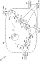
- FIG. 1 presents a flow diagram of an example method embodiment 100 of the disclosure and FIG. 2 presents an example apparatus 200 embodiment of the disclosure.
- the method includes measuring optical powers (e.g., FIG. 1 , step 105) at different wavelengths of an individual wavelength communication channel along an optical fiber path of an optical communication system (e.g., FIG. 2 , optical communication system 202, optical fiber path 205).
- the method further includes forming an estimate of nonlinear optical degradation of an optical data signal along the optical fiber path based on the measured optical powers at the different wavelengths (e.g., FIG. 1 , step 110).
- the different wavelengths can be any two or more of the sub-channels of an individual wavelength communication channel e.g., a single WDM optical channel.
- the different wavelengths are evenly distributed across the width of the individual wavelength communication channel, e.g., to facilitate collecting information about both linear and nonlinear optical degradation.
- the measuring optical powers can be performed at, e.g., 3, 10, 20, 30, 100, 200 or more different wavelengths of the individual wavelength communication channel, e.g., to improve the accuracy of the spectral information collected about linear and nonlinear optical degradation.
- the optical power measurements at the different wavelength of the individual wavelength communication channel can be made over a frequency range greater than the channel symbol-rate of the optical data signal.
- forming the estimate of nonlinear optical degradation includes evaluating a function linear in the optical powers of the individual wavelength channel (e.g., FIG. 1 , step 115).
- the function linear in the optical powers can include a weighted sum of power spectral densities determined from the measuring of the optical powers at the different wavelengths of the individual wavelength communication channel (e.g., using eqs. (1) and (2)).
- the measuring optical powers (step 105) can be performed adjacent to or at different optical amplifiers along the optical fiber path (e.g., FIG.1 , step 120, FIG. 2 , at least three different in-line optical amplifiers 210a, 210b, 210c). Alternatively or additionally, the measuring optical powers (step 105) can be performed at various nodes along the optical fiber path (e.g., FIG. 2 , nodes 225a, 225b).
- some such embodiments of the method can further include determining whether or not to send the optical data signal along the optical fiber path (e.g., FIG. 1 , step 125). For instance, if it is determined that substantial optical degradation is present, the method may include determining to not use the optical fiber path, to not add the wavelength channel thereto, to drop the wavelength channel therefrom and/or to change the modulation rate and/or format on the wavelength channel. Also, if the optical degradation cannot be reduced, e.g., even by making various adjustments to operating parameters of the optical wavelength channel, as explained below, then it may be determined, as part of step 125, to switch the optical wavelength channel to a different optical fiber path of the system 202).
- any such embodiments of the method can further include determining whether or not to perform one or more different adjustments, performed singly or in combination together, to reduce the nonlinear optical degradation on a data wavelength-channel of the individual wavelength communication channel or a different wavelength communication channel (e.g., FIG. 1 step 127). For instance, if it is determined that optical degradation would be substantially reduced by adjustments to operating parameter(s) of the optical fiber path, and then the optical fiber path would be useable for sending the optical data signal, appropriate adjustments of operating parameter(s) may be made to reduce nonlinear optical degradation over the optical fiber path.
- the method can include determining whether to adjust the optical powers (e.g., including adjusting an optical power profile) at the different wavelengths of the individual communication channel or at wavelengths of a different wavelength communication channel (e.g., FIG. 1 , step 130).
- the optical powers e.g., including adjusting an optical power profile
- the method can further include determining whether or not to adjust an optical data transmission rate over the optical fiber path on the individual or a different wavelength communication channel based on the estimate (e.g., FIG. 1 , step 135).
- the method can further include determining whether or not to change a constellation for optical symbols for optical data transmission over the optical fiber path on the individual or a different wavelength communication channel based on the estimate (e.g., FIG. 1 , step 140).
- the method can further include determining whether or not to change a number of used optical wavelength channels for optical data transmission over the optical fiber path via the individual or a different wavelength communication channel based on the estimate (e.g., FIG. 1 , step 145).
- the method can further include determining whether or not to change a spacing of used wavelength channels for optical data transmission over the optical fiber path, e.g., via the individual wavelength communication channel or a different wavelength communication channel, based on the estimate (e.g., FIG. 1 , step 150).
- ⁇ NLT may be determined to have a negative value and/or LNLR may be determined to have a value of less than 3, then substantial nonlinear optical degradation could be considered to be, e.g., present in the optical data signal.
- it could be determined (e.g., determined by a network controller such as further described in the context of FIG. 2 ) to perform one or more of the adjustments of operating parameters (e.g., FIG. 1 , to cause one or more of steps 130, 135, 140, 145, and 150).
- the optical data signal could be considered to have a nonlinear optical degradation below a threshold and it could therefore, be determined to not require adjustment(s) to be made to such operating parameters of the optical path.
- the steps in the method can be repeated at a rate that is at least as high as the expected rate of change in the optical fiber path. For instance, if it was expected that one or more optical wavelength channels would be added or dropped at a particular rate (e.g., once per minute), then it would be desirable for the power of the optical amplifiers in the optical fiber path to be, at least adjusted at a comparable rate.
- the individual wavelength communication channel can be in any of the common optical telecommunication wavelength bands, such as the Original (e.g., about 1260 to about 1360 nm), Extended (e.g., about 1360 to about 1460 nm), Short (e.g., about 1460 to about 1530 nm), Conventional (C-band, e.g., about 1530 to about 1565 nm), Long (from e.g., 1565 to about 1625 nm) or Ultralong (e.g., about 1625 to about 1675 nm) wavelength bands.
- the individual wavelength communication channel can, e.g., have a width of 50, 100, 150, or 200 GHz).
- Another embodiment is an apparatus.
- embodiments of the apparatus 200 can include an optical fiber path of an optical communication system (e.g., FIG. 2 path 205, system 202).
- the optical fiber path can include one or more optical spectrum analyzers (e.g., FIG. 2 , a plurality of OSAs 215 a ...215 e ).
- Each of the OSAs can be connected to measure optical powers at a corresponding location along the optical fiber path 205 (e.g., FIG. 1 , step 105).
- each of the OSAs can be configured to measure values of optical powers at the different wavelengths (e.g., 3, 10, 20, 30, 100, 200 or more different wavelengths) in a same individual wavelength communication channel of the optical communication system.
- the apparatus can also include a computing device (e.g., FIG. 2 , computing device 220).
- the computing device can be connected to receive the values of optical powers measured by at least one of the OSAs.
- the computing device can be configured to form an estimate of nonlinear optical degradation of an optical data signal along the optical fiber path based on the measured optical powers (e.g., FIG. 1 , step 110), e.g., based on the estimates using eq. (1) and (2).
- some of the optical spectrum analyzers can be configured to measure optical power spectra at or adjacent to different optical amplifiers along the optical fiber path (e.g., FIG. 1 , step 120; FIG. 2 , OSAs 215a, 215b, 215c at or adjacent to the three in-line optical amplifiers 210a, 210b, 210c, respectively).
- some of the optical spectrum analyzers can be configured to measure optical power spectra the optical fiber path at one or more optical nodes along the optical fiber path (e.g., OSAs 215d, 215e, at nodes 225a, 225b respectively).
- the computing device can be configured to form the estimate by evaluating a function linear in the optical powers, e.g., the function linear in the optical powers including a weighted sum of power spectral densities determined from the measuring optical powers at the different wavelengths (e.g., FIG.1 , step 115, eq. (1)).
- the computing device can include an integrated circuit (e.g., an application specific integrated circuit).
- the computing device may include a non-transient volatile memory module to store the offset weight and weight values (e.g., w o ...w N ) and the measured values of optical powers (e.g., a stored telemetry data-base) and a central processing unit that is programmed to perform operations on the offset weight and weight values and the measure values of optical powers to form the estimate of nonlinear optical degradation.
- the computing device can be part of one of the OSAs in the optical fiber path while in other embodiments; the computing device can be a separate device.
- the computing device can be connected to an optical node of the optical fiber path (e.g., FIG. 2 , monitor 220 connected to nodes 225c).
- the computing device can be configured to extract the values of optical powers measured by the OSAs from information received on an optical supervisory channel.
- the computing device is configured to send the extracted values of optical powers measured by the optical spectrum analyzers, over the optical supervisory channel, to a network controller.
- optical supervisory channels can be configured carry a variety of information about optical signals as well as information about the operating conditions along an optical path.
- each of the OSAs in the optical fiber path can be configured to send the values of optical powers via the optical supervisory channel to the computing device which can then use the sent values to form the estimate of nonlinear optical degradation.
- Some embodiments of the apparatus further include a network controller (e.g., FIG. 2 , optical network controller 230).
- a network controller e.g., FIG. 2 , optical network controller 230.
- Embodiments of the network controller can be configured, based on the estimate(s), to determine whether or not to send the optical data signal along the optical fiber path 205 (e.g., FIG. 1 , step 125).
- Embodiments of the network controller can be configured, based on the estimate(s), to determine whether or not to cause one or more adjustments of optical operating parameters to be performed (e.g., FIG. 1 step 127).
- the one of more adjustments can include adjusting the optical powers (e.g., including adjusting an optical power profile) at the different wavelengths of the individual wavelength communication channel or wavelengths of a different wavelength communication channel (step 130).
- the network controller can cause one or more amplifiers (e.g., one or more of in-line amplifiers 210a, 210b, 210c) in the optical fiber path to increase or decrease the optical power at the different wavelengths of the individual wavelength communication channel, or at wavelengths of a different wavelength communication channel, in the path 205.
- the one of more adjustments can include: adjusting an optical data transmission rate over the optical fiber path on the individual or a different wavelength communication channel (step 135); changing a constellation for optical symbols for optical data transmission over the optical fiber path on the individual or a different wavelength communication channel (step 140); changing a number of used wavelength channels for optical data transmission over the optical fiber path via the individual or a different wavelength communication channel (step 145); or adjusting a spacing of the used wavelength channels for optical data transmission over the optical fiber path via the individual or a different wavelength communication channel (step 150). Any such adjustments can be implemented to reduce the optical degradation (e.g., linear and/or non-linear optical degradation) on a data wavelength-channel of the individual or the different wavelength communication channel.
- the optical degradation e.g., linear and/or non-linear optical degradation
- the network controller can cause one or more optical data transceivers, ODTs, in the optical fiber path (e.g., FIG. 2 , ODT 235a, 235b) to make the adjustment or one or more of the optical data transmission rate, the constellation for optical symbols, the number of used wavelength channels or the spacing of the used wavelength channels the optical power in the optical path or another optical path.
- one or more optical nodes e.g., nodes 225a, 225b, 225c
- ROADM reconfigurable optical add drop multiplexers
- the network controller can cause the update and storage of the offset weight and set of weight values (w o ...w N ) in the computing device for subsequent applications to form the estimate of nonlinear optical degradation.
- Embodiments of the apparatus can include multiple spans of optical fibers (including pairs of fibers) configured to carry the individual wavelength communication channel and other wavelength communication channels. Each such optical fiber may be connected to carry such optical wavelength channel(s) in a single, or both, directions along the optical fiber path (e.g., FIG. 2 , optical fiber spans 240a..240g of path 205).
- Embodiments of the apparatus can be part of an optical network (e.g., FIG. 2 , optical network 250 under the management of an optical network controller 230) which in turn can be part of the optical communication system 202.
- Embodiments of the optical network may include part or all of long-haul, regional, or metropolitan networks for the communication of wavelength division multiplexing (WDM) transmissions via a set of the wavelength communication channels.
- WDM wavelength division multiplexing
- the optical communication system 202 can be any system where significant nonlinear optical degradation can be present.
- the optical communication system 202 can be a coherent optical communication system, in which the optical data signal is generated by phase-modulating data onto an optical carrier , e.g., according to binary phase shift keying, quadrature phase shift keying, quadrature amplitude modulation or another format for phase shift keying.
- the optical communication system 202 can be a non-coherent optical communication system.
- Embodiments of the OSA can be any device able to measure optical power at various wavelengths (e.g., two or more wavelengths) across a single optical channel to thereby provide the data to construct a PSD curve.
- the OSA can be, or be included in, an optical power monitor configured to extract several points per channel slot (e.g. about 100 points for each 50 GHz slot in some embodiments).
- embodiments of various optical amplifiers can include erbium-doped fiber amplifiers (EDFA), forward or backward Raman amplifiers, hybrid Raman-EDFA amplifiers or other optical amplifiers familiar to those skilled in the pertinent art that are capable of changing the power of the optical signal in the optical fiber path, e.g., semiconductor optical amplifiers.
- EDFA erbium-doped fiber amplifiers
- forward or backward Raman amplifiers e.g., hybrid Raman-EDFA amplifiers or other optical amplifiers familiar to those skilled in the pertinent art that are capable of changing the power of the optical signal in the optical fiber path, e.g., semiconductor optical amplifiers.
- Embodiments of the optical data transceivers include any device capable of sending information encoded with optical signals in one direction and receiving information via optical signals from the opposite direction.
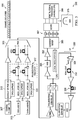
- FIG. 3 presents a block diagram of an experimental WDM optical communication system 300 and further presents example optical performance curves with varying optical path distances.
- the system 300 was configured for the transmission of 81 coherent quadrature phase-shift keying (QPSK) wavelength channels, in parallel.
- the investigated central optical wavelength channel e.g., FIG. 3 , individual channel 1
- the investigated central optical wavelength channel is surrounded by a comb of 79 wavelength channels, which may be equally wavelength-spaced.
- FIG. 3 shows a sub-comb 305 of the 80 wavelength channels, which includes the central wavelength channel 1 and 20 surrounding channels (e.g., FIG. 3 , channels labeled as 2, 3, 4, 5 Jerusalem).
- the data-carrying central channel 1 was generated by passing light from an external-cavity laser 307 (ECL) with a linewidth of about 100 KHz into polarization division multiplexed (PDM), in-phase/quadrature-phase (I/Q) optical data modulators 310 to be data-modulated.
- the investigated central channel was then multiplexed with two combs, one of 39 wavelength channels and one of 40 wavelength channels formed from optical carriers of 100 GHz-spaced distributed feedback lasers 312, which are data-modulated by dedicated optical wavelength channel, I/Q optical data modulators 315, followed by polarization emulation (via polarization emulator 317) of output optical signals therefrom, i.e., to approximately pseudo-randomly simulated polarization division multiplexing.
- each optical data modulator 315 was driven by digital-to-analog converters 320 (DACs) to produce optical data at 65 Gbit/s per polarization, e.g., from independent 216-long pseudo-random quaternary sequences (PRQSs). All optical channels were optically multiplexed via a wavelength selective switch 325 (WSS) that selected every other channel from each input port.
- WDM wavelength division multiplex light
- the wavelength division multiplex light (WDM) was sent to a looped transmission light path link 330 of several (e.g., three as illustrated) 100km-long large effective-area fiber (LEAF) spans 332, with 4.3 ps/nm/km dispersion at 1550 nm.
- the multiplex was amplified through an in-line erbium-doped fiber amplifier 334 (EDFA).
- EDFA in-line erbium-doped fiber amplifier 334
- DCF dispersion-compensating fiber 336
- RDPS residual dispersion per span
- the investigated central channel 1 was extracted with a WSS 360.
- the last optical amplifier 362 ensured an about constant optical power to feed one input of the coherent optical mixer 365 whose optical outputs were monitored with two balanced pairs of photodiodes 367.
- the photocurrents were sampled using an optical spectrum analyzer 375 (OSA) with 20 GHz electrical bandwidth. 100 ⁇ s-long series of samples were stored and processed offline on a computer 380.
- the computer 380 was programmed to perform digital signal processing (DSP) including skew adjustments and normalization, polarization demultiplexing with blind equalization based on constant-modulus algorithm, frequency offset compensation.
- DSP digital signal processing
- the PSD was estimated by using rectangular windowing with Bartlett's method ( M.S. Bartlett: 'Smoothing Periodograms from Time-Series with Continuous Spectra,' Nature, vol. 161, pp. 686-687, 1948. DOI:10.1038/161686a0 , incorporated by reference herein in its entirety).
- the experiment outcomes were used for optimizing the weights (optimization using as metric the mean-squared-error (MSE) where power correction is the dependent variable and the PSD vector entries are the explanatory variables).
- MSE mean-squared-error
- FIG. 4 presents results from an example application power correction based upon ⁇ NLT outputs in an example optical communication system (e.g., FIG. 3 , test system 300) as determined using method and apparatus embodiments of the disclosure (e.g., FIGs. 1-2 , method 100 and apparatus 200).
- the actual launch power can be corrected according to the predicted ( ⁇ NLT), resulting in eq (3):
- ⁇ SNR SNR P + ⁇ NLT ⁇ ⁇ SNR P dB
- SNR(P) correspond to the bell curve, i.e., SNR at a given power P.
- the dashed line represents the maximum achievable SNR gain according to Gaussian-noise model theory.
- FIG. 5 presents evaluated offset and weight values (e.g., using eq. 1, to evaluate w o ...w N , and an input PSD curve) of an example optical communication wavelength channel, as obtained using method and apparatus embodiments of the disclosure.
- the ⁇ NLT was evaluated according to eq (1).
- a weighted integration of the input vectors if positive, corresponds to the linear regime, and, if negative corresponds to the nonlinear regime.
- the solid line in the figure shows the shape of the input PSDi curve (e.g., the first 150 points of PSDi) and open circles and vertical lines show the relative weights (w i ) determined.
- Region A corresponds to a dark spectral region with no launched light.
- the light power found in this region corresponds to amplified spontaneous emission (ASE) noise.
- Weights in this region are positive, because they contribute to the linear region.
- Region B includes a steep slope part of the PSD curve. This region is the boundary of the modulated signal PSD and has a wavelength range that enlarges or shrinks with the nonlinear effects. The weights here are negative since they contribute to the nonlinear region. The weights are relatively high since they account for the nonlinearities in this region.
- Region C corresponds to a transition between the upper plateau and the modulation boundary.
- Region C the weights oscillate around zero and substantially sum to zero, suggesting that these weights provide, at most, limited information on the noise quality.
- Region D corresponds to an upper plateau of the PSD around the middle of the optical wavelength channel, where the PSD is high. Similar to region A, region D includes information regarding linear noise as signified by the positive weights therein.
- FIG. 6 presents an example plot of ⁇ NLT standard deviation versus number of half-spectrum PSD points obtained from an experimental optical communication system using method and apparatus embodiments of the disclosure.
- the ⁇ NLT standard deviation is a measure of the accuracy of performance improvement from power correction such as shown in FIG. 4 .
- the ⁇ NLT standard deviation decreased monotonically for an increasing number of PSD points, reaching a value about 1 dB at a PSD number, which in some embodiments, can correspond to obtaining about 1 PSD measurement per 500 MHz interval in the optical wavelength channel (e.g., sub-comb channel).
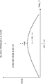
- FIG. 7 shows a relationship between the nonlinear threshold ( ⁇ NLT) and the linear-to-nonlinear ratio according to a perturbative model.
- ⁇ NLT nonlinear threshold
- GN Gaussian-noise
- SNR equals signal-to-noise ratio
- P ASE amplified spontaneous emission noise power
- P TRX transceiver impairments noise
- P NL nonlinear distortion power
- a NL nonlinear coefficient of the optical fiber path
- P is the launch power per channel.
- Eq (4) gives the bell curve shown in FIG. 7 , where the SNR is expressed as a function of the launch power, specifically FIG. 1 shows qualitative bell curve, normalized to the NLT, (e.g., the optimal launch power).
- direct measurements of the SNR as a function of the total power of and optical wavelength channel can be used during training to obtain values of ⁇ NLT so that the offset w 0 and the weights w 1 ... w N can be obtained from the solutions of eq (1).
Landscapes
- Physics & Mathematics (AREA)
- Electromagnetism (AREA)
- Engineering & Computer Science (AREA)
- Computer Networks & Wireless Communication (AREA)
- Signal Processing (AREA)
- Nonlinear Science (AREA)
- Optical Communication System (AREA)
Priority Applications (1)
| Application Number | Priority Date | Filing Date | Title |
|---|---|---|---|
| EP19305782.5A EP3754868A1 (de) | 2019-06-18 | 2019-06-18 | Volloptischer intrakanal-multiwellenlängen-linear-zu-nichtlinearer leistungsverhältnismonitor |
Applications Claiming Priority (1)
| Application Number | Priority Date | Filing Date | Title |
|---|---|---|---|
| EP19305782.5A EP3754868A1 (de) | 2019-06-18 | 2019-06-18 | Volloptischer intrakanal-multiwellenlängen-linear-zu-nichtlinearer leistungsverhältnismonitor |
Publications (1)
| Publication Number | Publication Date |
|---|---|
| EP3754868A1 true EP3754868A1 (de) | 2020-12-23 |
Family
ID=67220742
Family Applications (1)
| Application Number | Title | Priority Date | Filing Date |
|---|---|---|---|
| EP19305782.5A Withdrawn EP3754868A1 (de) | 2019-06-18 | 2019-06-18 | Volloptischer intrakanal-multiwellenlängen-linear-zu-nichtlinearer leistungsverhältnismonitor |
Country Status (1)
| Country | Link |
|---|---|
| EP (1) | EP3754868A1 (de) |
Cited By (2)
| Publication number | Priority date | Publication date | Assignee | Title |
|---|---|---|---|---|
| CN114978304A (zh) * | 2022-05-12 | 2022-08-30 | 上海交通大学 | 光放大器增益谱测量方法、系统及装置 |
| WO2024091257A1 (en) * | 2022-10-25 | 2024-05-02 | Halliburton Energy Services, Inc. | Extending fiber optic sensing |
Citations (4)
| Publication number | Priority date | Publication date | Assignee | Title |
|---|---|---|---|---|
| US20030137653A1 (en) * | 2001-11-30 | 2003-07-24 | Keisuke Kawabata | Method and apparatus for measuring wavelength dispersion value and/or nonlinear coefficient of optical fibers |
| US20040208534A1 (en) * | 2002-02-08 | 2004-10-21 | Ar Card | Method of WDM channel tagging and monitoring, and apparatus |
| WO2014019631A1 (en) * | 2012-08-03 | 2014-02-06 | Telefonaktiebolaget L M Ericsson (Publ) | Method of optimizing optical signal quality in an optical communications link, optical network element and optical communications link |
| WO2018215850A1 (en) * | 2017-05-24 | 2018-11-29 | Ciena Corporation | Adjustment of control parameters of section of optical fiber network and power control in an optical fiber network |
-
2019
- 2019-06-18 EP EP19305782.5A patent/EP3754868A1/de not_active Withdrawn
Patent Citations (4)
| Publication number | Priority date | Publication date | Assignee | Title |
|---|---|---|---|---|
| US20030137653A1 (en) * | 2001-11-30 | 2003-07-24 | Keisuke Kawabata | Method and apparatus for measuring wavelength dispersion value and/or nonlinear coefficient of optical fibers |
| US20040208534A1 (en) * | 2002-02-08 | 2004-10-21 | Ar Card | Method of WDM channel tagging and monitoring, and apparatus |
| WO2014019631A1 (en) * | 2012-08-03 | 2014-02-06 | Telefonaktiebolaget L M Ericsson (Publ) | Method of optimizing optical signal quality in an optical communications link, optical network element and optical communications link |
| WO2018215850A1 (en) * | 2017-05-24 | 2018-11-29 | Ciena Corporation | Adjustment of control parameters of section of optical fiber network and power control in an optical fiber network |
Non-Patent Citations (2)
| Title |
|---|
| M.S. BARTLETT: "Smoothing Periodograms from Time-Series with Continuous Spectra", NATURE, vol. 161, 1948, pages 686 - 687 |
| SABAPATHI T ET AL: "Mitigation of nonlinearities in fiber optic DWDM system", OPTIK, vol. 185, 1 May 2019 (2019-05-01), pages 657 - 664, XP085716374, ISSN: 0030-4026, DOI: 10.1016/J.IJLEO.2019.02.073 * |
Cited By (4)
| Publication number | Priority date | Publication date | Assignee | Title |
|---|---|---|---|---|
| CN114978304A (zh) * | 2022-05-12 | 2022-08-30 | 上海交通大学 | 光放大器增益谱测量方法、系统及装置 |
| CN114978304B (zh) * | 2022-05-12 | 2023-08-25 | 上海交通大学 | 光放大器增益谱测量方法、系统及装置 |
| WO2024091257A1 (en) * | 2022-10-25 | 2024-05-02 | Halliburton Energy Services, Inc. | Extending fiber optic sensing |
| GB2642572A (en) * | 2022-10-25 | 2026-01-14 | Halliburton Energy Services Inc | Extending fiber optic sensing |
Similar Documents
| Publication | Publication Date | Title |
|---|---|---|
| US10784980B2 (en) | Adjustment of control parameters of section of optical fiber network | |
| US20120219285A1 (en) | In-band optical signal to noise ratio monitoring technique | |
| EP3590210B1 (de) | Systeme und verfahren zur optischen leistungsüberwachung auf multiband-pilottonbasis | |
| US6934479B2 (en) | Wavelength division multiplexing optical communication system and wavelength division multiplexing optical communication method | |
| US10142022B1 (en) | Adjustment of control parameters of section of optical fiber network | |
| US8285148B2 (en) | Spectral efficiency estimation in coherent receivers | |
| US20100135663A1 (en) | Repeater and repeating method | |
| US11489597B2 (en) | Method and network control device for optimizing performance of a multi-span optical fiber network | |
| EP3544208B1 (de) | Automatische messung der rauschleistung eines transponders | |
| US9037002B2 (en) | Pre-emphasis control method and optical transmission system | |
| EP3376688B1 (de) | Verfahren zur überwachung und korrektur der nachbarkanalpenalty bei kohärenter optischer übertragung | |
| JP2004289707A (ja) | 波長多重光信号の品質監視方法および装置、並びに、それを用いた光伝送システム | |
| CN102598707A (zh) | 一种均衡链路性能的方法和装置 | |
| EP3844896B1 (de) | Überwachung der leistung eines optischen netzwerks mit niedrigleistungslücken und einem pilotton | |
| Kaeval et al. | Characterization of the optical spectrum as a service | |
| Fei et al. | Estimating EDFA output power with an efficient numerical modeling framework | |
| EP3754868A1 (de) | Volloptischer intrakanal-multiwellenlängen-linear-zu-nichtlinearer leistungsverhältnismonitor | |
| CN109196796B (zh) | 光通信 | |
| Oda et al. | Network capacity improvement by quality of transmission estimator with learning process | |
| Searcy et al. | Experimental study of bandwidth loading with modulated signals vs. ASE noise in 400ZR single-span transmission | |
| US20040208577A1 (en) | Methods for in-service wavelength upgrade and system performance optimization in WDM optical networks | |
| Kaeval et al. | Exploring channel probing to determine coherent optical transponder configurations in a long-haul network | |
| Burtsev et al. | Experimental study of closed-form GN model using real-time m-QAM transceivers with symbol rate up to 69 GBd | |
| Rahman et al. | Performance evaluation of multi-ONU customers access network using spectrum slicing and duplication techniques | |
| US20250293771A1 (en) | Optical line physical parameters calibation in presence of edfa total power monitors |
Legal Events
| Date | Code | Title | Description |
|---|---|---|---|
| PUAI | Public reference made under article 153(3) epc to a published international application that has entered the european phase |
Free format text: ORIGINAL CODE: 0009012 |
|
| STAA | Information on the status of an ep patent application or granted ep patent |
Free format text: STATUS: THE APPLICATION HAS BEEN PUBLISHED |
|
| AK | Designated contracting states |
Kind code of ref document: A1 Designated state(s): AL AT BE BG CH CY CZ DE DK EE ES FI FR GB GR HR HU IE IS IT LI LT LU LV MC MK MT NL NO PL PT RO RS SE SI SK SM TR |
|
| AX | Request for extension of the european patent |
Extension state: BA ME |
|
| STAA | Information on the status of an ep patent application or granted ep patent |
Free format text: STATUS: REQUEST FOR EXAMINATION WAS MADE |
|
| 17P | Request for examination filed |
Effective date: 20210623 |
|
| RBV | Designated contracting states (corrected) |
Designated state(s): AL AT BE BG CH CY CZ DE DK EE ES FI FR GB GR HR HU IE IS IT LI LT LU LV MC MK MT NL NO PL PT RO RS SE SI SK SM TR |
|
| STAA | Information on the status of an ep patent application or granted ep patent |
Free format text: STATUS: EXAMINATION IS IN PROGRESS |
|
| 17Q | First examination report despatched |
Effective date: 20221201 |
|
| STAA | Information on the status of an ep patent application or granted ep patent |
Free format text: STATUS: THE APPLICATION IS DEEMED TO BE WITHDRAWN |
|
| 18D | Application deemed to be withdrawn |
Effective date: 20241210 |