EP3755232B1 - Lenkbarer katheter mit piezoelektrischem wandler - Google Patents
Lenkbarer katheter mit piezoelektrischem wandler Download PDFInfo
- Publication number
- EP3755232B1 EP3755232B1 EP19703365.7A EP19703365A EP3755232B1 EP 3755232 B1 EP3755232 B1 EP 3755232B1 EP 19703365 A EP19703365 A EP 19703365A EP 3755232 B1 EP3755232 B1 EP 3755232B1
- Authority
- EP
- European Patent Office
- Prior art keywords
- pull wire
- piezoelectric transducer
- catheter
- conductive member
- disposed
- Prior art date
- Legal status (The legal status is an assumption and is not a legal conclusion. Google has not performed a legal analysis and makes no representation as to the accuracy of the status listed.)
- Active
Links
Images


Classifications
-
- A—HUMAN NECESSITIES
- A61—MEDICAL OR VETERINARY SCIENCE; HYGIENE
- A61B—DIAGNOSIS; SURGERY; IDENTIFICATION
- A61B8/00—Diagnosis using ultrasonic, sonic or infrasonic waves
- A61B8/12—Diagnosis using ultrasonic, sonic or infrasonic waves in body cavities or body tracts, e.g. by using catheters
-
- A—HUMAN NECESSITIES
- A61—MEDICAL OR VETERINARY SCIENCE; HYGIENE
- A61M—DEVICES FOR INTRODUCING MEDIA INTO, OR ONTO, THE BODY; DEVICES FOR TRANSDUCING BODY MEDIA OR FOR TAKING MEDIA FROM THE BODY; DEVICES FOR PRODUCING OR ENDING SLEEP OR STUPOR
- A61M25/00—Catheters; Hollow probes
- A61M25/01—Introducing, guiding, advancing, emplacing or holding catheters
- A61M25/0105—Steering means as part of the catheter or advancing means; Markers for positioning
- A61M25/0133—Tip steering devices
- A61M25/0147—Tip steering devices with movable mechanical means, e.g. pull wires
-
- A—HUMAN NECESSITIES
- A61—MEDICAL OR VETERINARY SCIENCE; HYGIENE
- A61B—DIAGNOSIS; SURGERY; IDENTIFICATION
- A61B8/00—Diagnosis using ultrasonic, sonic or infrasonic waves
- A61B8/44—Constructional features of the ultrasonic, sonic or infrasonic diagnostic device
- A61B8/4444—Constructional features of the ultrasonic, sonic or infrasonic diagnostic device related to the probe
- A61B8/445—Details of catheter construction
-
- A—HUMAN NECESSITIES
- A61—MEDICAL OR VETERINARY SCIENCE; HYGIENE
- A61M—DEVICES FOR INTRODUCING MEDIA INTO, OR ONTO, THE BODY; DEVICES FOR TRANSDUCING BODY MEDIA OR FOR TAKING MEDIA FROM THE BODY; DEVICES FOR PRODUCING OR ENDING SLEEP OR STUPOR
- A61M25/00—Catheters; Hollow probes
- A61M25/01—Introducing, guiding, advancing, emplacing or holding catheters
- A61M25/0105—Steering means as part of the catheter or advancing means; Markers for positioning
- A61M25/0133—Tip steering devices
- A61M25/0158—Tip steering devices with magnetic or electrical means, e.g. by using piezo materials, electroactive polymers, magnetic materials or by heating of shape memory materials
-
- A—HUMAN NECESSITIES
- A61—MEDICAL OR VETERINARY SCIENCE; HYGIENE
- A61M—DEVICES FOR INTRODUCING MEDIA INTO, OR ONTO, THE BODY; DEVICES FOR TRANSDUCING BODY MEDIA OR FOR TAKING MEDIA FROM THE BODY; DEVICES FOR PRODUCING OR ENDING SLEEP OR STUPOR
- A61M25/00—Catheters; Hollow probes
- A61M25/01—Introducing, guiding, advancing, emplacing or holding catheters
- A61M25/0105—Steering means as part of the catheter or advancing means; Markers for positioning
- A61M2025/0166—Sensors, electrodes or the like for guiding the catheter to a target zone, e.g. image guided or magnetically guided
-
- A—HUMAN NECESSITIES
- A61—MEDICAL OR VETERINARY SCIENCE; HYGIENE
- A61M—DEVICES FOR INTRODUCING MEDIA INTO, OR ONTO, THE BODY; DEVICES FOR TRANSDUCING BODY MEDIA OR FOR TAKING MEDIA FROM THE BODY; DEVICES FOR PRODUCING OR ENDING SLEEP OR STUPOR
- A61M2205/00—General characteristics of the apparatus
- A61M2205/02—General characteristics of the apparatus characterised by a particular materials
- A61M2205/0272—Electro-active or magneto-active materials
- A61M2205/0294—Piezoelectric materials
Definitions
- the invention relates to a steerable catheter for use in medical applications. More specifically the invention relates to a steerable catheter that includes a piezoelectric transducer at its distal end.
- the piezoelectric transducer may be used in various sensing and actuation applications. In one contemplated application the piezoelectric transducer may be used to track a position of a distal end of the catheter respective an ultrasound field of a beamforming ultrasound imaging probe.
- Steerable catheters are used in numerous medical diagnostic and therapeutic applications. Cardio-vascular, intravascular and pulmonary procedures are three such exemplary applications in which the steerable nature of the catheter is important in navigating the pathways in the body. Steerable catheters are often equipped with one or more so-called pull wires that extend along the length of the catheter to an anchor point at its distal end. The anchor point is offset from the longitudinal axis of the catheter such that by pulling on the pull-wire an axially-offset force imparts a curvature on the catheter's distal end. Such a catheter is described in document US6224587B1 .
- transducers for sensing and actuation during medical procedures.
- Piezoelectric materials are sometimes used in these transducers due to the wide range of transducer functions they offer.
- Specific, nonlimiting examples include the transducing, i.e. conversion of signals from one form of energy to another, of ultrasound, acoustic, vibration, and thermal energy.
- Such transducers may be used in a wide range of applications including ultrasound-based tracking, ultrasound imaging, blood flow monitoring, heart rate determination, temperature monitoring, and high frequency ultrasound "HIFU" treatment.
- an ultrasound-based position determination system is described in which a ultrasound sensor mounted on a needle is used to detect the ultrasound signals from a beamforming ultrasound imaging probe.
- a document US 2014/0257130 A1 relates to medical devices such as pull wire catheters.
- One disclosed pull wire catheter may include an elongate tubular member having a proximal end region, a distal end region and a lumen extending between the proximal end region and the distal end region.
- a therapeutic element may be disposed at the distal end region.
- a pull wire may extend through the lumen to the distal end region and may be fixed to the distal end region such that relative movement between the pull wire and the tubular member proximal region alters the distal end region.
- the pull wire may have a core comprising a first material having a first conductivity and a cladding comprising a second material having a second conductivity.
- FIG. 10 Another document US 2004/0176757 A1 relates to a cardiac ablation device for treating atrial fibrillation by directing and focusing ultrasonic waves into a ring-like ablation region.
- the device desirably is steerable and can be moved between a normal disposition, in which the ablation region lies parallel to the wall of the heart for ablating a loop-like lesion, and a canted disposition, in which the ring-like focal region is tilted relative to the wall of the heart, to ablate only a short, substantially linear lesion.
- the present invention seeks to provide a steerable medical catheter with improved electrical interconnection to a piezoelectric transducer at its distal end.
- the steerable medical catheter includes a tubular body having a longitudinal axis and a distal portion for insertion into a subject, a first pull wire, a second pull wire, and a piezoelectric transducer.
- the piezoelectric transducer includes a first electrode and a second electrode.
- the first pull wire and the second pull wire are each mechanically coupled to the tubular body at respective first and second offset positions with respect to the longitudinal axis for imparting a curvature on the distal portion of the catheter.
- the first pull wire is electrically connected to the first electrode of the piezoelectric transducer and the second pull wire is electrically connected to the second electrode of the piezoelectric transducer.
- the tubular body of the steerable catheter includes a reinforcement layer.
- the reinforcement layer includes a conductive material that surrounds and thereby electrically shields the first pull wire and the second pull wire.
- a steerable medical catheter is described with particular reference to a tracking application.
- the position of a cardio-vascular catheter is tracked by means of ultrasound signals detected by a piezoelectric transducer attached to the catheter.
- the steerable medical catheter finds application in other medical procedures including intravascular and pulmonary procedures.
- the piezoelectric transducer finds application in sensing and actuation applications beyond position-tracking, such as for example ultrasound imaging, blood flow monitoring, heart rate determination, temperature monitoring, and high frequency ultrasound "HIFU" treatment.
- Fig. 1 illustrates a steerable medical catheter 100 that includes first pull wire 104, second pull wire 105 and piezoelectric transducer 106.
- Fig. 1B shows a section through B - B' of the three-dimensional view of Fig. 1A
- Fig. 1C shows a corresponding section through distal end 103 at C - C'.
- Steerable medical catheter 100 has a tubular body 101 with longitudinal axis 102 and a distal portion 103 for insertion into a subject.
- Steerable medical catheter 100 is in general flexible, however, distal portion 103 may exhibit a greater degree of flexibility than elsewhere along its length in order to help guide the catheter through the complex pathways in the vasculature.
- Distal end 103 may be formed from a material having a higher flexibility, or with a thinner diameter, as compared to elsewhere along tubular body 101.
- Distal end 103 may alternatively include one or more cutout portions, or include a plurality of grooves or holes, for example in a criss-cross pattern, or be shaped in the form of a spiral, along distal end 103 in order to provide a greater degree of flexibility as compared to elsewhere along tubular body 101.
- first pull wire 104 and second pull wire 105 are each mechanically coupled to tubular body 101 at respective first and second offset positions 109, 110 with respect to longitudinal axis 102 for imparting a curvature on distal portion 103.
- Pull wires 104, 105 may for example each be attached to the wall of tubular body 101 or to frame 117 as described later.
- Pull wires 104, 105 are each guided within tubular body 101 by separate lumens 111, 112 that each extend parallel to longitudinal axis 102.
- the pull wires extend between a tensioning mechanism (not shown) at a proximal end of tubular body 101 and their respective first and second offset positions 109, 110.
- the pull wire lumens each include an electrically insulating wall that provides electrical isolation.
- tension on one of the pull wires provides an off-axis force at distal end 103 by means of its offset position with respect to longitudinal axis 102, thereby causing distal end 103 to adopt a curved shape.
- a user can navigate changes in direction in the vasculature and ensure a smooth passage of steerable medical catheter 100 to the intended position within the body.
- Offset positions 109, 110 are illustrated in Fig. 1 as being in diametrically opposite positions respective longitudinal axis 102 and thereby provide for a curvature in each of two opposing directions.
- offset positions 109, 110 are also contemplated, such as arranging offset positions 109, 110 with a rotational separation about longitudinal axis 102 that is for example 90 degrees, or indeed any angle between for example 5 degrees and 180 degrees.
- offset positions 109, 110 are illustrated as being equal in Fig. 1 , these off-axis radii may alternatively be unequal.
- Alternative arrangements having more than two pull wires are also contemplated.
- piezoelectric transducer 106 includes first electrode 107 and a second electrode 108. At distal portion 103, first pull wire 104 is electrically connected to first electrode 107 and second pull wire 105 is electrically connected to second electrode 108.
- first pull wire 104 is electrically connected to first electrode 107
- second pull wire 105 is electrically connected to second electrode 108.
- Piezoelectric transducer 106 is illustrated in Fig. 1C as a layer that is wrapped around a portion of tubular body 101.
- First electrode 107 and second electrode 108 are disposed on the major surfaces of this layer, and consequently in the section illustrated in Fig. 1C first electrode 107 and second electrode 108 are disposed, respectively on the inner and outer surfaces of piezoelectric transducer 106.
- Electrical contact between each electrode 107, 108 and its corresponding pull wire 104, 105 may for example be achieved using a bondwire, electrically conductive glue or paint, and so forth.
- Piezoelectric transducer 103 may for example be provided by a layer of Polyvinylidene fluoride, i.e. PVDF, or a layer of PVDF co-polymer such as polyvinylidene fluoride trifluoroethylene (P(VDF-TrFE)) or a layer of PVDF ter-polymer such as P(VDF-TrFE-CTFE).
- PVDF Polyvinylidene fluoride
- PVDF polyvinylidene fluoride trifluoroethylene
- PVDF ter-polymer such as P(VDF-TrFE-CTFE
- the exemplary PVDF layer may be disposed on a layer of pressure sensitive adhesive, i.e. PSA - coated PET in the form of a transducer strip.
- Pressure sensitive adhesives form a class of materials that form an adhesive bond upon application of pressure. Sheets of such pressure sensitive adhesives include product 2811CL made by the 3M corporation.
- Piezoelectric transducer 106 may alternatively be made from other soft, or indeed hard piezoelectric materials. Fabrication techniques including the use of dip-coating, molding, sol gel deposition are also contemplated, as is the use of pre-fabricated discrete piezoelectric elements made from polymer materials as well as conventional hard piezoelectric materials such as PZT.
- steerable medical catheter 100 may include central lumen 116.
- Central lumen 116 may be sized to receive an interventional device such as a catheter or a needle, or another medical tool for performing a procedure at the distal end of medical catheter 100.
- tubular body 101 includes inner liner 113, reinforcement layer 114, and outer sheath 115.
- Inner liner may for example be formed from fluoropolymer materials such as Fluorinated ethylene propylene, i.e. FEP, or Polytetrafluoroethylene, i.e. PTFE.
- inner liner 113 is preferably in the form of a tube having a cylindrical cross section.
- Reinforcement layer 114 serves to reinforce tubular body 101 against kinking and ovalisation of the liner during bending and may for example be in the form of a braid or one or more coils, and may be formed from materials such as type 314 or 316 stainless steel, Polyester, and Polyether ether ketone, i.e. PEEK.
- Outer sheath 115 may for example be formed from materials such as Polyether block amides such as the material known as PEBAX that is trademarked by Arkema, Colombes, France, FEP, Nylon, Polyethylene, Polyurethane, Ethylene tetrafluoroethylene, i.e. ETFE, or PTFE.
- Inner liner 113, reinforcement layer 114 and outer sheath 115 each extend coaxially along longitudinal axis 102 of catheter 100 such that reinforcement layer 114 is disposed between inner liner 113 and outer sheath 115.
- Inner liner 113 defines central lumen 116, and this is coaxial with the longitudinal axis 102. Central lumen 116 allows a medical procedure to be carried out at the distal end of catheter 100 when an interventional device inserted therein.
- first pull wire lumen 111 and second pull wire lumen 112 are each disposed in inner liner 113.
- Inner liner 113 with lumens 111, 112 may for example be formed in a single extrusion process.
- Reinforcement layer 114 may optionally include a conductive material. In the construction illustrated in Fig. 1 , reinforcement layer 114 surrounds first pull wire 104 and second pull wire 105 and thereby provides electrical shielding.
- steerable medical catheter 100 includes a steering frame.
- the steering frame includes a first anchor point disposed at first offset position 109 and a second anchor point disposed at second offset position 110.
- first pull wire 104 and second pull wire 105 are attached, respectively, to the first anchor point and the second anchor point such that the steering frame mechanically couples first pull wire 104 and second pull wire 105 to the tubular body 101.
- steering frame 117 has a cylindrical shape.
- the steering frame may alternatively have other shapes such as a plate, a cap, a bar and so forth.
- steering frame 117 is in this example formed from a unitary piece of material.
- Pull wires 104, 105 are attached to steering frame 117 at anchor points at corresponding offset positions 109, 110.
- steering frame 117 is preferably formed from an electrically insulating material. Polymers and ceramics are examples of suitable materials for steering frame 117. Materials with a high Shore Hardness value are preferred in view of providing a reproducible curve in the catheter's distal portion 103. Acrylonitrile butadiene styrene, i.e. ABS, is a suitable polymer for steering frame 117 in this respect.
- steering frame 117 may include an inner lumen 118 that is arranged coaxially with longitudinal axis 102 of tubular body 101.
- inner lumen 118 may communicate with central lumen 116 to provide a continuous lumen along the length of steerable medical catheter 100.
- steering frame 117 may have a circumference 119 and piezoelectric transducer 106 may be disposed around this circumference.
- Piezoelectric transducer 106 may alternatively be disposed around a circumference of tubular body 101. Piezoelectric transducer 106 may thereby provide sensing or actuation around the circumference of the steerable medical catheter.
- Piezoelectric transducer 106 may be form a continuous band around the circumference or include a gap, or include one or more electrically-interconnected sub-elements with a gaps between each subelement.
- piezoelectric transducer 106 may at least in part be disposed on end face 120 of steering 117 in order to provide sensing or actuation in a corresponding direction.
- Steering frame 117 may alternatively be formed from a conductive material. Various metals including stainless steel may be used, and pull wires 104, 105 securely attached thereto by my means of e.g. welding in order to facilitate a strong anchor point.
- Fig. 2 illustrates a second exemplary steering frame 117.
- the second exemplary steering frame of Fig. 2 may be used in the position of item 117 in Fig. 1A and may be held in place by for example adhesive or friction provided by compressive forces from outer sheath 115.
- frame 117 in Fig. 2 includes first conductive member 121 and second conductive member 122. The first conductive member and the second conductive member are separated by insulating layer 123.
- Insulating layer 123 consequently provides electrical isolation between pull wires 104, 105.
- Insulating layer 123 may for example be provided by an electrically insulating adhesive, a polymer, a dielectric and so forth.
- the first anchor point is disposed on the first conductive member 121 and the second anchor point is disposed on the second conductive member 122.
- first conductive member 121 is provided by a first portion of a cylindrical shell
- second conductive member 122 is provided by a second portion of a cylindrical shell. The first portion and the second portion are mechanically attached to each other along the axial extent of the steering frame 117 by insulating layer 123 to provide the cylindrical shell.
- the insulating layer extends along longitudinal axis 102 and conductive members 121, 122 are provided by two half-cylinders.
- Optional inner lumen 118 may also be included in steering frame 117, inner lumen 118 being arranged coaxially with longitudinal axis 102 of tubular body 101.
- piezoelectric transducer 106 may be disposed around the circumference of steering frame 117.
- Fig. 3 illustrates a third exemplary steering frame 117.
- first conductive member 121 and second conductive member 122 of the steering frame of Fig. 3 each include an interlocking step along longitudinal axis 102.
- the interlocking steps provide increased strength along longitudinal axis 102.
- Piezoelectric transducer 106 is omitted in Fig. 3 for ease of illustration.
- pull wires 104, 105 are both attached at a proximal end of frame 117 whereas in Fig.
- each pull wire 104, 105 is attached to an interlocking step of its respective conductive member 121, 122 such that tensile force on each pull wire 104, 105 compressively forces the interlocking steps together. This improves the strength of the joint between the conductive members 121, 122.
- Anchor points 109 and 110 may for example be positioned in end face 120 of each of conductive members 109, 110 in Fig. 3B .
- Electrical insulation between pull wire 105 that passes through opposite conductive member 121 in Fig. 3B may be achieved by for example providing pull wire 105 with an insulation layer on the wire or on the surface of the lumen, or an epoxy well around pull wire 105.
- Fig. 4 illustrates a fourth exemplary steering frame 117.
- Steering frame 117 in Fig. 4 includes first conductive member 121 that is provided by a first cylindrical member, and second conductive member 122 that is provided by a second cylindrical member.
- the first cylindrical member and the second cylindrical member are arranged coaxially such that the first cylindrical member is within the second cylindrical member.
- insulating layer 123 is disposed between the first cylindrical member and the second cylindrical member.
- piezoelectric transducer 106 is disposed around the circumference of the second cylindrical member.
- Fig. 4A piezoelectric transducer 106 is disposed around the circumference of the second cylindrical member.
- the first cylindrical member includes an extended portion 124 that extends beyond the axial extent of the second cylindrical member and piezoelectric transducer 106 is disposed around the circumference of the first cylindrical member.
- Anchor points at first and second offset positions 109, 110 are provided, respectively in first conductive member 121 and second conductive member 122.
- Electrical isolation in the form of e.g. an epoxy well around pull wire 105 may be used to electrically isolate pull wire 105 from first conductive member 121.
- an insulation layer may be provided on pull wire 105 or on the surface of its lumen.
- Fig. 5 illustrates a fifth exemplary steering frame 117.
- Steering frame 117 in Fig. 5 includes first conductive member 121 and second conductive member 122.
- First conductive member 121 is in the form of a first washer having an axis that is aligned with longitudinal axis 102
- second conductive member 122 is in the form of a second washer having an axis that is aligned with the longitudinal axis 102.
- piezoelectric transducer 106 is sandwiched between the first washer and the second washer such that first pull wire 104 is electrically connected to the first electrode 107 of the piezoelectric transducer 106 via the first washer, and such that second pull wire 105 is electrically connected to second electrode 108 of piezoelectric transducer 106 via the second washer.
- Piezoelectric transducer 106 in Fig. 5 may for example be provided by an electrode-coated PVDF layer that extends from a contact region between conductive members 121, 122 onto the circumference of frame 117 or tubular body 101.
- a hard piezoelectric material may be disposed between axially-separated conductive members 121, 122.
- one or more additional piezoelectric transducers may be disposed at axially-separated positions along longitudinal axis 102 of tubular body 101. These additional transducers may optionally be electrically connected in parallel with piezoelectric transducer 106. This provides additional transducer functionality without the need for additional electrical interconnections along the length of the catheter.
- Such parallel-connected transducers may be provided by for example electrically-interconnecting discrete piezoelectric transducers, or by disposing patterned electrodes on a continuous PVDF layer such that there are electrodes only on both sides of the layer at locations where transducers are desired.
- a steerable medical catheter that has one pull wire that is electrically connected to piezoelectric transducer 106, and an electrically conductive reinforcement layer 114.
- This steerable medical catheter includes a tubular body 101 having a longitudinal axis 102 and a distal portion 103 for insertion into a subject; a pull wire, a piezoelectric transducer 106 comprising a first electrode 107 and a second electrode 108.
- the tubular body has an inner liner 113, an electrically conductive reinforcement layer 114, and an outer sheath 115.
- the inner liner 113, the reinforcement layer 114 and the outer sheath 115 each extend coaxially along the longitudinal axis 102 of the catheter 100 such that the reinforcement layer 114 is disposed between the inner liner 113 and the outer sheath 115.
- the inner liner 113 defines a central lumen 116 that is coaxial with the longitudinal axis 102 for receiving an interventional device.
- the pull wire 104 is mechanically coupled to the tubular body at an offset positions 109 with respect to the longitudinal axis 102 for imparting a curvature on the distal portion 103 of the catheter.
- the pull wire 104 is electrically connected to the first electrode 107 of the piezoelectric transducer 106, and the electrically conductive reinforcement layer 114 is electrically connected to the second electrode 108 of the piezoelectric transducer 106.
- the steerable medical catheter is provided with a piezoelectric device that has simplified electrical interconnections.
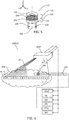
- Fig. 6 illustrates an exemplary ultrasound-based position determination system UBPDS in which the steerable medical catheters described herein may be used.
- Ultrasound-based position determination system UBPDS includes steerable medical catheter 100; a beamforming ultrasound imaging probe BUIP configured to generate an ultrasound field UF, an image reconstruction unit IRU configured to provide a reconstructed ultrasound image corresponding to the ultrasound field UF of the beamforming ultrasound imaging probe BUIP; a position determination unit PDU configured to compute a position of the piezoelectric transducer 116 of the interventional device 110 respective the ultrasound field UF based on ultrasound signals transmitted between the beamforming ultrasound imaging probe BUIP and the piezoelectric transducer 116; and an icon providing unit IPU configured to provide an icon in the reconstructed ultrasound image based on the computed position of the piezoelectric transducer 116.
- beamforming ultrasound imaging probe BUIP is in communication with image reconstruction unit IRU, imaging system processor ISP, imaging system interface ISI and display DISP.
- units BUIP, IRU, ISP, ISI and DISP may be provided by a conventional ultrasound imaging system.
- the units IRU, ISP, ISI and DISP are conventionally located in a console that is in wired or wireless communication with beamforming ultrasound imaging probe BUIP.
- Some of units IRU, ISP, ISI and DISP may alternatively be incorporated within beamforming ultrasound imaging probe BUIP.
- Beamforming ultrasound imaging probe BUIP generates ultrasound field UF.
- a 2D beamforming ultrasound imaging probe BUIP that includes a linear ultrasound transceiver array that transmits and receives ultrasound energy within an ultrasound field UF which intercepts volume of interest VOI.
- the ultrasound field is fan-shaped in Fig. 6 and includes multiple ultrasound beams B 1..k that together provide the illustrated image plane. Note that whilst a fan-shaped beam is illustrated in Fig. 6 for the purposes of illustration the invention is not limited to a particular shape of ultrasound field.
- Imaging system interface ISI An operator may plan an ultrasound procedure via imaging system interface ISI. Once an operating procedure is selected, imaging system interface ISI triggers imaging system processor ISP to execute application-specific programs that generate and interpret the signals transmitted to and detected by beamforming ultrasound imaging probe BUIP.
- a memory (not shown) may be used to store such programs. The memory may for example store ultrasound beam control software that is configured to control the sequence of ultrasound signals transmitted by and/or received by beamforming ultrasound imaging probe BUIP.
- Image reconstruction unit IRU which may alternatively form part of imaging system processor ISP. Image reconstruction unit IRU provides a reconstructed ultrasound image corresponding to ultrasound field UF of beamforming ultrasound imaging probe BUIP.
- IRU thereby provides an image corresponding to the image plane defined by ultrasound field UF and which thus intercepts volume of interest VOI.
- the image is subsequently displayed on display DISP.
- the reconstructed image may for example be an ultrasound Brightness-mode "B-mode” image, otherwise known as a "2D mode” image, a "C-mode” image or a Doppler mode image, or indeed any ultrasound image.
- piezoelectric transducer 106 may be tracked respective ultrasound field UF based on signals provided by position determination unit PDU and icon providing unit IPU.
- PDU and icon providing unit IPU are in communication with one another and units BUIP, IRU, ISP, ISI and DISP, i.e. the conventional ultrasound imaging system as illustrated by the interconnecting arrows.
- units PDU and IPU may be incorporated within a memory or a processor of the conventional ultrasound imaging system.
- the position of piezoelectric transducer 106 is computed respective ultrasound field UF by position determination unit PDU based on ultrasound signals transmitted between beamforming ultrasound imaging probe BUIP and piezoelectric transducer 106.
- piezoelectric transducer 106 is a detector that receives ultrasound signals corresponding to beams B 1..k .
- Position determination unit PDU identifies the position of piezoelectric transducer 106 by correlating the ultrasound signals emitted by beamforming ultrasound imaging probe BUIP with the ultrasound signals detected by piezoelectric transducer 106.
- Icon providing unit IPU subsequently provides an icon in the reconstructed ultrasound image based on the computed position of piezoelectric transducer 106.
- the correlation determines the best fit position of piezoelectric transducer 106 respective ultrasound field UF based on i) the amplitudes of the ultrasound signals corresponding to each beam B 1..k that are detected by piezoelectric transducer 106, and based on ii) the time delay, i.e. time of flight, between emission of each beam B 1..k and its detection by piezoelectric transducer 106.
- This may be illustrated as follows. When piezoelectric transducer 106 is in the vicinity of ultrasound field UF, ultrasound signals from the nearest of beams B 1..k to the transducer will be detected with a relatively larger amplitude whereas more distant beams will be detected with relatively smaller amplitudes.
- the beam that is detected with the largest amplitude is identified as the one that is closest to piezoelectric transducer 106.
- This beam defines the in-plane angle ⁇ IPA between beamforming ultrasound imaging probe BUIP and piezoelectric transducer 106.
- the corresponding range depends upon the time delay, i.e. the time of flight, between the emission of the largest-amplitude beam B 1..k and its subsequent detection. The range is determined by multiplying the time delay by the speed of ultrasound propagation.
- the range and corresponding in-plane angle ⁇ IPA of the beam detected with the largest amplitude can be used to identify the best-fit position of piezoelectric transducer 106 respective ultrasound field UF.
- piezoelectric transducer 106 may be an emitter that emits one or more ultrasound pulses. Such pulses may for example be emitted during tracking frames that are interleaved between the imaging frames of the conventional ultrasound imaging system.
- beamforming ultrasound imaging probe BUIP may operate in a receive-only mode in which it listens for ultrasound signals originating from the vicinity of ultrasound field UF. Beamforming ultrasound imaging probe BUIP is thus configured as a one-way receive-only beamformer during such tracking frames.
- Position determination unit PDU identifies from which beam of virtual beams B 1..k the pulse(s) originated by applying delays to the receiver elements of beamforming ultrasound imaging probe BUIP. The delays correspond to each of virtual beams B 1..k .
- position determination unit PDU may use a correlation procedure that, based on the maximum amplitude and time of flight, identifies the closest beam B 1..k to the position at which the ultrasound signal was emitted, and the corresponding range to piezoelectric transducer 106.
- Icon providing unit IPU subsequently provides an icon in the reconstructed ultrasound image based on the identified position of piezoelectric transducer 106.
- a correlation procedure may again be used to determine the best-fit position of piezoelectric transducer 106 respective ultrasound field UF for each tracking frame.
- piezoelectric transducer 106 may be configured to act as both a receiver and an emitter, or include a separate receiver and emitter. In this configuration piezoelectric transducer 106 may be triggered to emit one or more ultrasound pulses upon receipt of an ultrasound signal from beamforming ultrasound imaging probe BUIP. In this way the pulse(s) emitted by piezoelectric transducer 106 during an imaging mode are received by beamforming ultrasound imaging probe BUIP appear as an echo in the reconstructed ultrasound at an in-plane angular position, i.e. in an image line, that corresponds to the relevant beam B 1..k . Piezoelectric transducer 106 thus appears as a bright spot in the reconstructed image. Position determination unit PDU may subsequently identify this bright spot in the reconstructed image and thus compute a position of piezoelectric transducer 106 respective ultrasound field UF.
- the exemplified beamforming ultrasound imaging probe BUIP is only one example of a beamforming ultrasound imaging system in which steerable medical catheter 100 may be used.
- Steerable medical catheter 100 also finds application in ultrasound-based position determination systems that include other types of 2D or 3D beamforming ultrasound imaging systems. These may include for example a "TRUS" transrectal ultrasonography probe, an "IVUS" intravascular ultrasound probe, a "TEE” transesophageal probe, a "TTE" transthoracic probe, a “TNE” transnasal probe, an "ICE” intracardiac probe.
- the piezoelectric transducer also finds application in other sensing and actuation applications in the medical field beyond position determination.
Landscapes
- Health & Medical Sciences (AREA)
- Life Sciences & Earth Sciences (AREA)
- Engineering & Computer Science (AREA)
- Heart & Thoracic Surgery (AREA)
- Biophysics (AREA)
- Biomedical Technology (AREA)
- Animal Behavior & Ethology (AREA)
- Veterinary Medicine (AREA)
- Public Health (AREA)
- General Health & Medical Sciences (AREA)
- Hematology (AREA)
- Anesthesiology (AREA)
- Pulmonology (AREA)
- Radiology & Medical Imaging (AREA)
- Surgery (AREA)
- Molecular Biology (AREA)
- Medical Informatics (AREA)
- Physics & Mathematics (AREA)
- Pathology (AREA)
- Nuclear Medicine, Radiotherapy & Molecular Imaging (AREA)
- Mechanical Engineering (AREA)
- Ultra Sonic Daignosis Equipment (AREA)
- Surgical Instruments (AREA)
- Media Introduction/Drainage Providing Device (AREA)
Claims (11)
- Lenkbarer medizinischer Katheter (100), umfassend:einen röhrenförmigen Körper (101) mit einer Längsachse (102) und einem distalen Abschnitt (103) zum Einführen in ein Subjekt;einen ersten Zugdraht (104);einen zweiten Zugdraht (105);einen piezoelektrischen Wandler (106), umfassend eine erste Elektrode (107) und eine zweite Elektrode (108);wobei der röhrenförmige Körper (101) ein erstes Zugdrahtlumen (111) und ein zweites Zugdrahtlumen (112) umfasst, die sich jeweils parallel zur Längsachse (102) erstrecken;wobei der erste Zugdraht (104) in dem ersten Zugdrahtlumen (111) angeordnet ist;wobei der zweite Zugdraht (105) in dem zweiten Zugdrahtlumen (112) angeordnet ist; undwobei das erste Zugdrahtlumen (111) und das zweite Zugdrahtlumen (112) jeweils eine elektrisch isolierende Lumenwand enthalten;wobei am distalen Abschnitt (103) des Katheters (100) der erste Zugdraht (104) und der zweite Zugdraht (105) jeweils mechanisch mit dem röhrenförmigen Körper an den jeweiligen ersten und zweiten Versatzpositionen (109, 110) in Bezug auf die Längsachse (102) gekoppelt sind zum Verleihen einer Krümmung auf den distalen Abschnitt (103) des Katheters;wobei am distalen Abschnitt (103) des Katheters der erste Zugdraht (104) elektrisch mit der ersten Elektrode (107) des piezoelektrischen Wandlers (106) verbunden ist und der zweite Zugdraht (105) elektrisch mit der zweiten Elektrode (108) des piezoelektrischen Wandlers (106) verbunden ist;dadurch gekennzeichnet, dass:der rohrförmige Körper (101) eine Innenauskleidung (113), eine Verstärkungsschicht (114) und eine Außenhülle (115) umfasst; unddie Innenauskleidung (113), die Verstärkungsschicht (114) und die Außenhülle (115) sich jeweils koaxial entlang der Längsachse (102) des Katheters (100) erstrecken, so dass die Verstärkungsschicht (114) zwischen der Innenauskleidung (113) und der Außenhülle (115) angeordnet ist; unddie Innenauskleidung (113) ein zentrales Lumen (116) definiert, das koaxial zur Längsachse (102) ist, um eine Interventionsvorrichtung aufzunehmen; undam distalen Abschnitt (103) des Katheters (100) das erste Zugdrahtlumen (111) und das zweite Zugdrahtlumen (112) jeweils in der Innenauskleidung (113) angeordnet sind; unddie Verstärkungsschicht (114) ein leitendes Material zum elektrischen Abschirmen des ersten Zugdrahtes (104) und des zweiten Zugdrahtes (105) umfasst.
- Lenkbarer medizinischer Katheter (100) nach Anspruch 1, ferner umfassend einen Lenkrahmen (117);
wobei der Lenkrahmen (117) einen ersten Ankerpunkt umfasst, der an der ersten Versatzposition (109) angeordnet ist, und einen zweiten Ankerpunkt, der an der zweiten Versatzposition (110) angeordnet ist; und
wobei der erste Zugdraht (104) und der zweite Zugdraht (105) jeweils an dem ersten Ankerpunkt und dem zweiten Ankerpunkt angebracht sind, so dass der Lenkrahmen den ersten Zugdraht (104) und den zweiten Zugdraht (105) mechanisch zum röhrenförmigen Körper (101) koppelt. - Lenkbarer medizinischer Katheter (100) nach Anspruch 2, wobei der Lenkrahmen (117) ferner ein inneres Lumen (118) umfasst, wobei das innere Lumen koaxial zur Längsachse (102) des röhrenförmigen Körpers (101) angeordnet ist.
- Lenkbarer medizinischer Katheter (100) nach Anspruch 3, wobei der Lenkrahmen (117) einen Umfang (119) umfasst; und
wobei der piezoelektrische Wandler (106) um den Umfang des Lenkrahmens angeordnet ist. - Lenkbarer medizinischer Katheter (100) nach einem der Ansprüche 2 bis 4, wobei der Lenkrahmen (117) eine Endfläche (120) umfasst; und
wobei der piezoelektrische Wandler (106) auf der Endfläche des Lenkrahmens angeordnet ist. - Lenkbarer medizinischer Katheter (100) nach einem der Ansprüche 2 bis 5, wobei der Lenkrahmen (117) ein erstes leitendes Element (121) und ein zweites leitendes Element (122) umfasst, wobei das erste leitende Element und das zweite leitende Element durch eine Isolierschicht (123) getrennt sind;
wobei der erste Ankerpunkt auf dem ersten leitenden Element (121) angeordnet ist und der zweite Ankerpunkt auf dem zweiten leitenden Element (122) angeordnet ist. - Lenkbarer medizinischer Katheter (100) nach Anspruch 6, wobei das erste leitende Element (121) durch einen ersten Abschnitt einer zylindrischen Hülle bereitgestellt wird und wobei das zweite leitende Element (122) durch einen zweiten Abschnitt einer zylindrischen Hülle bereitgestellt wird;
wobei der erste Abschnitt und der zweite Abschnitt entlang der axialen Ausdehnung des Lenkrahmens (117) durch die Isolierschicht (123) mechanisch miteinander verbunden sind, um die zylindrische Hülle bereitzustellen; und wobei
der piezoelektrische Wandler (106) um den Umfang der zylindrischen Hülle angeordnet ist. - Lenkbarer medizinischer Katheter (100) nach Anspruch 6, wobei das erste leitende Element (121) von einem ersten zylindrischen Element bereitgestellt wird und wobei das zweite leitende Element (122) von einem zweiten zylindrischen Element bereitgestellt wird;
wobei das erste zylindrische Element und das zweite zylindrische Element koaxial angeordnet sind, so dass sich das erste zylindrische Element innerhalb des zweiten zylindrischen Elements befindet, und so dass die Isolierschicht (123) zwischen dem ersten zylindrischen Element und dem zweiten zylindrischen Element angeordnet ist; und wobei entweder:i) der piezoelektrische Wandler (106) um den Umfang des zweiten zylindrischen Elements herum angeordnet ist; oderii) wobei das erste zylindrische Element einen verlängerten Abschnitt (124) enthält, der sich über die axiale Ausdehnung des zweiten zylindrischen Elements hinaus erstreckt, und der piezoelektrische Wandler (106) um den Umfang des ersten zylindrischen Elements angeordnet ist. - Lenkbarer medizinischer Katheter (100) nach einem der Ansprüche 2 bis 5, wobei der Lenkrahmen (117) ein erstes leitendes Element (121) und ein zweites leitendes Element (122) umfasst, wobei das erste leitende Element (121) die Form einer ersten Unterlegscheibe mit einer Achse hat, die mit der Längsachse (102) ausgerichtet ist, und das zweiten leitenden Elements (122) die Form einer zweiten Unterlegscheibe mit einer Achse hat, die mit der Längsachse (102) ausgerichtet ist;
wobei der piezoelektrische Wandler (106) zwischen der ersten Unterlegscheibe und der zweiten Unterlegscheibe angeordnet ist, so dass der erste Zugdraht (104) über die erste Unterlegscheibe elektrisch mit der ersten Elektrode (107) des piezoelektrischen Wandlers (106) verbunden ist, und so dass der zweite Zugdraht (105) über die zweite Unterlegscheibe elektrisch mit der zweiten Elektrode (108) des piezoelektrischen Wandlers (106) verbunden ist. - Lenkbarer medizinischer Katheter (100) nach einem der vorhergehenden Ansprüchen, ferner umfassend mindestens einen zweiten piezoelektrischen Wandler;
wobei der piezoelektrische Wandler (106) und der mindestens zweite piezoelektrische Wandler; an axial getrennten Positionen entlang der Längsachse (102) des Rohrkörpers (101) angeordnet sind. - Lenkbarer medizinischer Katheter (100) nach Anspruch 10, wobei der piezoelektrische Wandler (106) und der mindestens zweite piezoelektrische Wandler elektrisch parallelgeschaltet sind.
Applications Claiming Priority (3)
| Application Number | Priority Date | Filing Date | Title |
|---|---|---|---|
| US201862632632P | 2018-02-20 | 2018-02-20 | |
| EP18167284.1A EP3552552A1 (de) | 2018-04-13 | 2018-04-13 | Lenkbarer katheter mit piezoelektrischem wandler |
| PCT/EP2019/053474 WO2019162150A1 (en) | 2018-02-20 | 2019-02-13 | Steerable catheter with piezoelectric transducer |
Publications (2)
| Publication Number | Publication Date |
|---|---|
| EP3755232A1 EP3755232A1 (de) | 2020-12-30 |
| EP3755232B1 true EP3755232B1 (de) | 2021-07-07 |
Family
ID=62001993
Family Applications (2)
| Application Number | Title | Priority Date | Filing Date |
|---|---|---|---|
| EP18167284.1A Withdrawn EP3552552A1 (de) | 2018-02-20 | 2018-04-13 | Lenkbarer katheter mit piezoelektrischem wandler |
| EP19703365.7A Active EP3755232B1 (de) | 2018-02-20 | 2019-02-13 | Lenkbarer katheter mit piezoelektrischem wandler |
Family Applications Before (1)
| Application Number | Title | Priority Date | Filing Date |
|---|---|---|---|
| EP18167284.1A Withdrawn EP3552552A1 (de) | 2018-02-20 | 2018-04-13 | Lenkbarer katheter mit piezoelektrischem wandler |
Country Status (4)
| Country | Link |
|---|---|
| US (1) | US11617860B2 (de) |
| EP (2) | EP3552552A1 (de) |
| JP (1) | JP6894583B2 (de) |
| CN (1) | CN111902089B (de) |
Families Citing this family (1)
| Publication number | Priority date | Publication date | Assignee | Title |
|---|---|---|---|---|
| CN221600067U (zh) | 2022-11-09 | 2024-08-27 | 巴德阿克塞斯系统股份有限公司 | 用于预防或治疗与血管通路装置相关的血栓形成的系统 |
Family Cites Families (17)
| Publication number | Priority date | Publication date | Assignee | Title |
|---|---|---|---|---|
| US4920980A (en) * | 1987-09-14 | 1990-05-01 | Cordis Corporation | Catheter with controllable tip |
| US6123699A (en) * | 1997-09-05 | 2000-09-26 | Cordis Webster, Inc. | Omni-directional steerable catheter |
| US6224587B1 (en) | 1999-11-22 | 2001-05-01 | C.R. Bard, Inc. | Steerable catheter |
| US7233820B2 (en) | 2002-04-17 | 2007-06-19 | Superdimension Ltd. | Endoscope structures and techniques for navigating to a target in branched structure |
| US7130700B2 (en) * | 2002-11-19 | 2006-10-31 | Medtronic, Inc. | Multilumen body for an implantable medical device |
| US6945956B2 (en) * | 2002-12-23 | 2005-09-20 | Medtronic, Inc. | Steerable catheter |
| WO2004073505A2 (en) * | 2003-02-20 | 2004-09-02 | Prorhythm, Inc. | Cardiac ablation devices |
| WO2005072391A2 (en) * | 2004-01-29 | 2005-08-11 | Ekos Corporation | Small vessel ultrasound catheter |
| WO2007124289A2 (en) * | 2006-04-21 | 2007-11-01 | Xtent, Inc. | Devices and methods for controlling and counting interventional elements |
| EP2355736A1 (de) * | 2008-09-02 | 2011-08-17 | Medtronic Ablation Frontiers LLC | Gespültes ablationskathetersystem und verfahren |
| FR2939139B1 (fr) | 2008-12-03 | 2012-12-21 | Arkema France | Composition comprenant du polypropylene et/ou un copolymere du propylene obtenus a partir de matieres renouvelables et utilisations |
| US8784800B2 (en) * | 2009-03-09 | 2014-07-22 | Medtronic, Inc. | Method of delivering cell therapy to a target site |
| EP2632339A4 (de) * | 2010-10-27 | 2015-04-22 | Gore Enterprise Holdings Inc | Bildgebungskatheter mit drehbarer anordnung |
| EP2455133A1 (de) * | 2010-11-18 | 2012-05-23 | Koninklijke Philips Electronics N.V. | Katheter mit kapazitiven mikrobearbeiteten Ultraschall-Transducern mit einstellbarer Brennweite |
| EP2840993A4 (de) * | 2012-04-24 | 2016-03-30 | Cibiem Inc | Endovaskuläre katheter und verfahren zur karotidkörperablation |
| US20140257130A1 (en) * | 2013-03-11 | 2014-09-11 | Boston Scientific Scimed, Inc. | Powered pull wire design for ablation catheters |
| CN105682725A (zh) * | 2013-08-23 | 2016-06-15 | 波士顿科学国际有限公司 | 导管和导管轴 |
-
2018
- 2018-04-13 EP EP18167284.1A patent/EP3552552A1/de not_active Withdrawn
-
2019
- 2019-02-13 JP JP2020543822A patent/JP6894583B2/ja not_active Expired - Fee Related
- 2019-02-13 EP EP19703365.7A patent/EP3755232B1/de active Active
- 2019-02-13 US US16/970,886 patent/US11617860B2/en active Active
- 2019-02-13 CN CN201980020631.0A patent/CN111902089B/zh active Active
Also Published As
| Publication number | Publication date |
|---|---|
| EP3552552A1 (de) | 2019-10-16 |
| JP2021511166A (ja) | 2021-05-06 |
| JP6894583B2 (ja) | 2021-06-30 |
| CN111902089A (zh) | 2020-11-06 |
| US20200376232A1 (en) | 2020-12-03 |
| US11617860B2 (en) | 2023-04-04 |
| EP3755232A1 (de) | 2020-12-30 |
| CN111902089B (zh) | 2023-03-07 |
Similar Documents
| Publication | Publication Date | Title |
|---|---|---|
| JP7430209B2 (ja) | 心臓内心エコー法(ice)用カテーテル先端アセンブリ | |
| JP7292448B2 (ja) | 十字状内部輪郭を備える内張り可変ブレード差的デュロメータ硬度複管路シャフト | |
| EP2358278B1 (de) | System und katheter zur bildführung und verfahren dafür | |
| US8412307B2 (en) | System and method for marking an anatomical structure in three-dimensional coordinate system | |
| US6277077B1 (en) | Catheter including ultrasound transducer with emissions attenuation | |
| JP4850697B2 (ja) | 多機能医療用カテーテル | |
| US9585634B2 (en) | Ultrasound catheter with rotatable transducer | |
| EP4304485B1 (de) | Katheter mit drehbarer bildanordnung | |
| US20080025145A1 (en) | Ultrasound Imaging Probe Featuring Wide Field of View | |
| EP2934334A2 (de) | Katheteranordnung mit verkürzter spitze | |
| EP3755232B1 (de) | Lenkbarer katheter mit piezoelektrischem wandler | |
| WO2019162150A1 (en) | Steerable catheter with piezoelectric transducer | |
| EP3755231B1 (de) | Interventionelle vorrichtung mit piezoelektrischem wandler | |
| JP7059438B2 (ja) | 電気接続を備える介入デバイス |
Legal Events
| Date | Code | Title | Description |
|---|---|---|---|
| STAA | Information on the status of an ep patent application or granted ep patent |
Free format text: STATUS: UNKNOWN |
|
| STAA | Information on the status of an ep patent application or granted ep patent |
Free format text: STATUS: THE INTERNATIONAL PUBLICATION HAS BEEN MADE |
|
| PUAI | Public reference made under article 153(3) epc to a published international application that has entered the european phase |
Free format text: ORIGINAL CODE: 0009012 |
|
| STAA | Information on the status of an ep patent application or granted ep patent |
Free format text: STATUS: REQUEST FOR EXAMINATION WAS MADE |
|
| 17P | Request for examination filed |
Effective date: 20200921 |
|
| AK | Designated contracting states |
Kind code of ref document: A1 Designated state(s): AL AT BE BG CH CY CZ DE DK EE ES FI FR GB GR HR HU IE IS IT LI LT LU LV MC MK MT NL NO PL PT RO RS SE SI SK SM TR |
|
| AX | Request for extension of the european patent |
Extension state: BA ME |
|
| GRAP | Despatch of communication of intention to grant a patent |
Free format text: ORIGINAL CODE: EPIDOSNIGR1 |
|
| STAA | Information on the status of an ep patent application or granted ep patent |
Free format text: STATUS: GRANT OF PATENT IS INTENDED |
|
| DAV | Request for validation of the european patent (deleted) | ||
| DAX | Request for extension of the european patent (deleted) | ||
| INTG | Intention to grant announced |
Effective date: 20210128 |
|
| GRAS | Grant fee paid |
Free format text: ORIGINAL CODE: EPIDOSNIGR3 |
|
| GRAA | (expected) grant |
Free format text: ORIGINAL CODE: 0009210 |
|
| STAA | Information on the status of an ep patent application or granted ep patent |
Free format text: STATUS: THE PATENT HAS BEEN GRANTED |
|
| AK | Designated contracting states |
Kind code of ref document: B1 Designated state(s): AL AT BE BG CH CY CZ DE DK EE ES FI FR GB GR HR HU IE IS IT LI LT LU LV MC MK MT NL NO PL PT RO RS SE SI SK SM TR |
|
| REG | Reference to a national code |
Ref country code: GB Ref legal event code: FG4D |
|
| REG | Reference to a national code |
Ref country code: AT Ref legal event code: REF Ref document number: 1407787 Country of ref document: AT Kind code of ref document: T Effective date: 20210715 |
|
| REG | Reference to a national code |
Ref country code: DE Ref legal event code: R096 Ref document number: 602019005955 Country of ref document: DE |
|
| REG | Reference to a national code |
Ref country code: IE Ref legal event code: FG4D |
|
| REG | Reference to a national code |
Ref country code: LT Ref legal event code: MG9D |
|
| REG | Reference to a national code |
Ref country code: NL Ref legal event code: MP Effective date: 20210707 |
|
| REG | Reference to a national code |
Ref country code: AT Ref legal event code: MK05 Ref document number: 1407787 Country of ref document: AT Kind code of ref document: T Effective date: 20210707 |
|
| PG25 | Lapsed in a contracting state [announced via postgrant information from national office to epo] |
Ref country code: LT Free format text: LAPSE BECAUSE OF FAILURE TO SUBMIT A TRANSLATION OF THE DESCRIPTION OR TO PAY THE FEE WITHIN THE PRESCRIBED TIME-LIMIT Effective date: 20210707 Ref country code: BG Free format text: LAPSE BECAUSE OF FAILURE TO SUBMIT A TRANSLATION OF THE DESCRIPTION OR TO PAY THE FEE WITHIN THE PRESCRIBED TIME-LIMIT Effective date: 20211007 Ref country code: AT Free format text: LAPSE BECAUSE OF FAILURE TO SUBMIT A TRANSLATION OF THE DESCRIPTION OR TO PAY THE FEE WITHIN THE PRESCRIBED TIME-LIMIT Effective date: 20210707 Ref country code: HR Free format text: LAPSE BECAUSE OF FAILURE TO SUBMIT A TRANSLATION OF THE DESCRIPTION OR TO PAY THE FEE WITHIN THE PRESCRIBED TIME-LIMIT Effective date: 20210707 Ref country code: FI Free format text: LAPSE BECAUSE OF FAILURE TO SUBMIT A TRANSLATION OF THE DESCRIPTION OR TO PAY THE FEE WITHIN THE PRESCRIBED TIME-LIMIT Effective date: 20210707 Ref country code: PT Free format text: LAPSE BECAUSE OF FAILURE TO SUBMIT A TRANSLATION OF THE DESCRIPTION OR TO PAY THE FEE WITHIN THE PRESCRIBED TIME-LIMIT Effective date: 20211108 Ref country code: NO Free format text: LAPSE BECAUSE OF FAILURE TO SUBMIT A TRANSLATION OF THE DESCRIPTION OR TO PAY THE FEE WITHIN THE PRESCRIBED TIME-LIMIT Effective date: 20211007 Ref country code: NL Free format text: LAPSE BECAUSE OF FAILURE TO SUBMIT A TRANSLATION OF THE DESCRIPTION OR TO PAY THE FEE WITHIN THE PRESCRIBED TIME-LIMIT Effective date: 20210707 Ref country code: ES Free format text: LAPSE BECAUSE OF FAILURE TO SUBMIT A TRANSLATION OF THE DESCRIPTION OR TO PAY THE FEE WITHIN THE PRESCRIBED TIME-LIMIT Effective date: 20210707 Ref country code: SE Free format text: LAPSE BECAUSE OF FAILURE TO SUBMIT A TRANSLATION OF THE DESCRIPTION OR TO PAY THE FEE WITHIN THE PRESCRIBED TIME-LIMIT Effective date: 20210707 Ref country code: RS Free format text: LAPSE BECAUSE OF FAILURE TO SUBMIT A TRANSLATION OF THE DESCRIPTION OR TO PAY THE FEE WITHIN THE PRESCRIBED TIME-LIMIT Effective date: 20210707 |
|
| PG25 | Lapsed in a contracting state [announced via postgrant information from national office to epo] |
Ref country code: PL Free format text: LAPSE BECAUSE OF FAILURE TO SUBMIT A TRANSLATION OF THE DESCRIPTION OR TO PAY THE FEE WITHIN THE PRESCRIBED TIME-LIMIT Effective date: 20210707 Ref country code: LV Free format text: LAPSE BECAUSE OF FAILURE TO SUBMIT A TRANSLATION OF THE DESCRIPTION OR TO PAY THE FEE WITHIN THE PRESCRIBED TIME-LIMIT Effective date: 20210707 Ref country code: GR Free format text: LAPSE BECAUSE OF FAILURE TO SUBMIT A TRANSLATION OF THE DESCRIPTION OR TO PAY THE FEE WITHIN THE PRESCRIBED TIME-LIMIT Effective date: 20211008 |
|
| REG | Reference to a national code |
Ref country code: DE Ref legal event code: R097 Ref document number: 602019005955 Country of ref document: DE |
|
| PG25 | Lapsed in a contracting state [announced via postgrant information from national office to epo] |
Ref country code: DK Free format text: LAPSE BECAUSE OF FAILURE TO SUBMIT A TRANSLATION OF THE DESCRIPTION OR TO PAY THE FEE WITHIN THE PRESCRIBED TIME-LIMIT Effective date: 20210707 |
|
| PLBE | No opposition filed within time limit |
Free format text: ORIGINAL CODE: 0009261 |
|
| STAA | Information on the status of an ep patent application or granted ep patent |
Free format text: STATUS: NO OPPOSITION FILED WITHIN TIME LIMIT |
|
| PG25 | Lapsed in a contracting state [announced via postgrant information from national office to epo] |
Ref country code: SM Free format text: LAPSE BECAUSE OF FAILURE TO SUBMIT A TRANSLATION OF THE DESCRIPTION OR TO PAY THE FEE WITHIN THE PRESCRIBED TIME-LIMIT Effective date: 20210707 Ref country code: SK Free format text: LAPSE BECAUSE OF FAILURE TO SUBMIT A TRANSLATION OF THE DESCRIPTION OR TO PAY THE FEE WITHIN THE PRESCRIBED TIME-LIMIT Effective date: 20210707 Ref country code: RO Free format text: LAPSE BECAUSE OF FAILURE TO SUBMIT A TRANSLATION OF THE DESCRIPTION OR TO PAY THE FEE WITHIN THE PRESCRIBED TIME-LIMIT Effective date: 20210707 Ref country code: EE Free format text: LAPSE BECAUSE OF FAILURE TO SUBMIT A TRANSLATION OF THE DESCRIPTION OR TO PAY THE FEE WITHIN THE PRESCRIBED TIME-LIMIT Effective date: 20210707 Ref country code: CZ Free format text: LAPSE BECAUSE OF FAILURE TO SUBMIT A TRANSLATION OF THE DESCRIPTION OR TO PAY THE FEE WITHIN THE PRESCRIBED TIME-LIMIT Effective date: 20210707 Ref country code: AL Free format text: LAPSE BECAUSE OF FAILURE TO SUBMIT A TRANSLATION OF THE DESCRIPTION OR TO PAY THE FEE WITHIN THE PRESCRIBED TIME-LIMIT Effective date: 20210707 |
|
| 26N | No opposition filed |
Effective date: 20220408 |
|
| PG25 | Lapsed in a contracting state [announced via postgrant information from national office to epo] |
Ref country code: IT Free format text: LAPSE BECAUSE OF FAILURE TO SUBMIT A TRANSLATION OF THE DESCRIPTION OR TO PAY THE FEE WITHIN THE PRESCRIBED TIME-LIMIT Effective date: 20210707 |
|
| PG25 | Lapsed in a contracting state [announced via postgrant information from national office to epo] |
Ref country code: MC Free format text: LAPSE BECAUSE OF FAILURE TO SUBMIT A TRANSLATION OF THE DESCRIPTION OR TO PAY THE FEE WITHIN THE PRESCRIBED TIME-LIMIT Effective date: 20210707 |
|
| REG | Reference to a national code |
Ref country code: CH Ref legal event code: PL |
|
| REG | Reference to a national code |
Ref country code: BE Ref legal event code: MM Effective date: 20220228 |
|
| PG25 | Lapsed in a contracting state [announced via postgrant information from national office to epo] |
Ref country code: LU Free format text: LAPSE BECAUSE OF NON-PAYMENT OF DUE FEES Effective date: 20220213 |
|
| PG25 | Lapsed in a contracting state [announced via postgrant information from national office to epo] |
Ref country code: LI Free format text: LAPSE BECAUSE OF NON-PAYMENT OF DUE FEES Effective date: 20220228 Ref country code: IE Free format text: LAPSE BECAUSE OF NON-PAYMENT OF DUE FEES Effective date: 20220213 Ref country code: CH Free format text: LAPSE BECAUSE OF NON-PAYMENT OF DUE FEES Effective date: 20220228 |
|
| PG25 | Lapsed in a contracting state [announced via postgrant information from national office to epo] |
Ref country code: BE Free format text: LAPSE BECAUSE OF NON-PAYMENT OF DUE FEES Effective date: 20220228 |
|
| PG25 | Lapsed in a contracting state [announced via postgrant information from national office to epo] |
Ref country code: MK Free format text: LAPSE BECAUSE OF FAILURE TO SUBMIT A TRANSLATION OF THE DESCRIPTION OR TO PAY THE FEE WITHIN THE PRESCRIBED TIME-LIMIT Effective date: 20210707 Ref country code: CY Free format text: LAPSE BECAUSE OF FAILURE TO SUBMIT A TRANSLATION OF THE DESCRIPTION OR TO PAY THE FEE WITHIN THE PRESCRIBED TIME-LIMIT Effective date: 20210707 |
|
| PG25 | Lapsed in a contracting state [announced via postgrant information from national office to epo] |
Ref country code: HU Free format text: LAPSE BECAUSE OF FAILURE TO SUBMIT A TRANSLATION OF THE DESCRIPTION OR TO PAY THE FEE WITHIN THE PRESCRIBED TIME-LIMIT; INVALID AB INITIO Effective date: 20190213 |
|
| PGFP | Annual fee paid to national office [announced via postgrant information from national office to epo] |
Ref country code: FR Payment date: 20240226 Year of fee payment: 6 |
|
| PG25 | Lapsed in a contracting state [announced via postgrant information from national office to epo] |
Ref country code: TR Free format text: LAPSE BECAUSE OF FAILURE TO SUBMIT A TRANSLATION OF THE DESCRIPTION OR TO PAY THE FEE WITHIN THE PRESCRIBED TIME-LIMIT Effective date: 20210707 |
|
| PG25 | Lapsed in a contracting state [announced via postgrant information from national office to epo] |
Ref country code: MT Free format text: LAPSE BECAUSE OF FAILURE TO SUBMIT A TRANSLATION OF THE DESCRIPTION OR TO PAY THE FEE WITHIN THE PRESCRIBED TIME-LIMIT Effective date: 20210707 |
|
| PG25 | Lapsed in a contracting state [announced via postgrant information from national office to epo] |
Ref country code: FR Free format text: LAPSE BECAUSE OF NON-PAYMENT OF DUE FEES Effective date: 20250228 |
|
| PGFP | Annual fee paid to national office [announced via postgrant information from national office to epo] |
Ref country code: GB Payment date: 20260223 Year of fee payment: 8 |
|
| PGFP | Annual fee paid to national office [announced via postgrant information from national office to epo] |
Ref country code: DE Payment date: 20260220 Year of fee payment: 8 |