EP3756231B1 - Medienzufuhrstruktur für elektrochemische vorrichtung - Google Patents
Medienzufuhrstruktur für elektrochemische vorrichtung Download PDFInfo
- Publication number
- EP3756231B1 EP3756231B1 EP19705305.1A EP19705305A EP3756231B1 EP 3756231 B1 EP3756231 B1 EP 3756231B1 EP 19705305 A EP19705305 A EP 19705305A EP 3756231 B1 EP3756231 B1 EP 3756231B1
- Authority
- EP
- European Patent Office
- Prior art keywords
- flow field
- medium channel
- channel
- mouth opening
- rim
- Prior art date
- Legal status (The legal status is an assumption and is not a legal conclusion. Google has not performed a legal analysis and makes no representation as to the accuracy of the status listed.)
- Active
Links
Images


Classifications
-
- H—ELECTRICITY
- H01—ELECTRIC ELEMENTS
- H01M—PROCESSES OR MEANS, e.g. BATTERIES, FOR THE DIRECT CONVERSION OF CHEMICAL ENERGY INTO ELECTRICAL ENERGY
- H01M8/00—Fuel cells; Manufacture thereof
- H01M8/02—Details
- H01M8/0202—Collectors; Separators, e.g. bipolar separators; Interconnectors
- H01M8/0204—Non-porous and characterised by the material
- H01M8/0206—Metals or alloys
-
- H—ELECTRICITY
- H01—ELECTRIC ELEMENTS
- H01M—PROCESSES OR MEANS, e.g. BATTERIES, FOR THE DIRECT CONVERSION OF CHEMICAL ENERGY INTO ELECTRICAL ENERGY
- H01M8/00—Fuel cells; Manufacture thereof
- H01M8/02—Details
- H01M8/0202—Collectors; Separators, e.g. bipolar separators; Interconnectors
- H01M8/0204—Non-porous and characterised by the material
- H01M8/0223—Composites
- H01M8/0228—Composites in the form of layered or coated products
-
- H—ELECTRICITY
- H01—ELECTRIC ELEMENTS
- H01M—PROCESSES OR MEANS, e.g. BATTERIES, FOR THE DIRECT CONVERSION OF CHEMICAL ENERGY INTO ELECTRICAL ENERGY
- H01M8/00—Fuel cells; Manufacture thereof
- H01M8/02—Details
- H01M8/0202—Collectors; Separators, e.g. bipolar separators; Interconnectors
- H01M8/0258—Collectors; Separators, e.g. bipolar separators; Interconnectors characterised by the configuration of channels, e.g. by the flow field of the reactant or coolant
-
- H—ELECTRICITY
- H01—ELECTRIC ELEMENTS
- H01M—PROCESSES OR MEANS, e.g. BATTERIES, FOR THE DIRECT CONVERSION OF CHEMICAL ENERGY INTO ELECTRICAL ENERGY
- H01M8/00—Fuel cells; Manufacture thereof
- H01M8/02—Details
- H01M8/0202—Collectors; Separators, e.g. bipolar separators; Interconnectors
- H01M8/0267—Collectors; Separators, e.g. bipolar separators; Interconnectors having heating or cooling means, e.g. heaters or coolant flow channels
-
- H—ELECTRICITY
- H01—ELECTRIC ELEMENTS
- H01M—PROCESSES OR MEANS, e.g. BATTERIES, FOR THE DIRECT CONVERSION OF CHEMICAL ENERGY INTO ELECTRICAL ENERGY
- H01M8/00—Fuel cells; Manufacture thereof
- H01M8/02—Details
- H01M8/0271—Sealing or supporting means around electrodes, matrices or membranes
- H01M8/0273—Sealing or supporting means around electrodes, matrices or membranes with sealing or supporting means in the form of a frame
-
- H—ELECTRICITY
- H01—ELECTRIC ELEMENTS
- H01M—PROCESSES OR MEANS, e.g. BATTERIES, FOR THE DIRECT CONVERSION OF CHEMICAL ENERGY INTO ELECTRICAL ENERGY
- H01M8/00—Fuel cells; Manufacture thereof
- H01M8/24—Grouping of fuel cells, e.g. stacking of fuel cells
- H01M8/241—Grouping of fuel cells, e.g. stacking of fuel cells with solid or matrix-supported electrolytes
-
- H—ELECTRICITY
- H01—ELECTRIC ELEMENTS
- H01M—PROCESSES OR MEANS, e.g. BATTERIES, FOR THE DIRECT CONVERSION OF CHEMICAL ENERGY INTO ELECTRICAL ENERGY
- H01M8/00—Fuel cells; Manufacture thereof
- H01M8/24—Grouping of fuel cells, e.g. stacking of fuel cells
- H01M8/2465—Details of groupings of fuel cells
- H01M8/2483—Details of groupings of fuel cells characterised by internal manifolds
-
- Y—GENERAL TAGGING OF NEW TECHNOLOGICAL DEVELOPMENTS; GENERAL TAGGING OF CROSS-SECTIONAL TECHNOLOGIES SPANNING OVER SEVERAL SECTIONS OF THE IPC; TECHNICAL SUBJECTS COVERED BY FORMER USPC CROSS-REFERENCE ART COLLECTIONS [XRACs] AND DIGESTS
- Y02—TECHNOLOGIES OR APPLICATIONS FOR MITIGATION OR ADAPTATION AGAINST CLIMATE CHANGE
- Y02E—REDUCTION OF GREENHOUSE GAS [GHG] EMISSIONS, RELATED TO ENERGY GENERATION, TRANSMISSION OR DISTRIBUTION
- Y02E60/00—Enabling technologies; Technologies with a potential or indirect contribution to GHG emissions mitigation
- Y02E60/30—Hydrogen technology
- Y02E60/50—Fuel cells
Definitions
- the DE 10 2014 104 017 A1 discloses an electrochemical device according to the preamble of claim 1.
- the US 2016/118673 A1 discloses an electrochemical device with media channels and flow fields which are in fluid communication via unspecified connecting channels, wherein edge sections on the flow field side and edge sections on the medium channel side are arranged partially offset and an orifice on the flow field side has a larger fluid passage area than an orifice on the medium channel side.
- the DE 20 2015 104 972 U1 discloses an electrochemical device in which edges of flow field-side orifices and of medium channel-side orifices of connecting channels are arranged offset from one another, wherein the flow field-side orifice has a larger fluid passage area than the medium channel-side orifice.
- the present invention is based on the object of creating an electrochemical device of the above-mentioned type in which a large volume flow of the fluid medium through the connecting channel can be achieved.
- the area of the connecting channel facing the flow field or the chemically active part of the membrane electrode assembly can be widened, thereby reducing the pressure loss in the connecting channel.
- the flow area from the connecting channel to the gas ports can be widened.
- the only requirement is that the connecting channels between separate media supply structures be lowered to the base level (e.g., the block area of the bipolar plate) in order to create a fluid-tight seal, for example, through a weld seam, in this intermediate area between two connecting channels, thus separating the fluid media conveyed in the two connecting channels from each other.
- the fluid medium guided in the medium channel, the connecting channel and the flow field can in particular be a fuel gas, an oxidizing agent or a coolant.
- the invention provides that the flow field-side mouth opening of the connecting channel has a larger fluid passage area than the medium channel-side mouth opening of the connecting channel.
- the flow field-side opening of the connecting channel opens at a corner region of the flow field.
- the connecting channel is arranged at a corner region of the active surface of the membrane electrode assembly of an electrochemical unit
- the present invention is particularly advantageous because, without an offset between at least one flow field-side edge of the flow field-side opening of the connecting channel and at least one medium channel-side edge of the medium channel-side mouth opening of the connecting channel, the flow field-side mouth opening would have a significantly smaller fluid passage area than the medium channel-side mouth opening of the connecting channel.
- the connecting channel can be widened on two sides (on the flow field side and on the medium channel side) or only on one side (on the medium channel side or, preferably, on the flow field side) or only have an offset between the flow field side orifice opening and the medium channel side orifice opening along the circumferential direction of the flow field.
- the first flow field-side edge of the flow field-side mouth opening of the connecting channel is preferably at a smaller distance from the first medium channel-side edge of the medium channel-side mouth opening of the connecting channel than from the second medium channel-side edge of the medium channel-side mouth opening.
- the second flow field-side edge of the flow field-side mouth opening of the connecting channel is preferably at a smaller distance from the second medium channel-side edge of the medium channel-side mouth opening of the connecting channel than from the first medium channel-side edge of the medium channel-side mouth opening.
- the first medium channel-side edge of the medium channel-side orifice is connected to the first flow field-side edge of the flow field-side orifice by a first edge line, which forms a first lateral boundary of the connecting channel
- the second medium channel-side edge of the medium channel-side orifice is connected to the second flow field-side edge of the flow field-side orifice by a second edge line, which forms a second lateral boundary of the connecting channel.
- first edge line and/or the second edge line is stepped.
- the connecting channel has a two-part structure and comprises a medium channel-side section and a flow field-side section, wherein a sudden change in the flow-through cross-section of the connecting channel occurs at the transition from the medium channel-side section to the flow field-side section of the connecting channel.
- the first edge line comprises a first medium-channel-side edge line section extending away from the first medium-channel-side edge of the medium-channel-side mouth opening substantially perpendicular to the circumferential direction of the flow field (and substantially perpendicular to the stacking direction) and a first flow-field-side edge line section extending away from the first flow-field-side edge of the flow-field-side mouth opening substantially perpendicular to the circumferential direction of the flow field (and perpendicular to the stacking direction).
- the second edge line comprises a second medium channel-side edge line section extending away from the second medium channel-side edge of the medium channel-side mouth opening substantially perpendicular to the circumferential direction of the flow field (and perpendicular to the stacking direction) and a second flow field-side edge line section extending away from the second flow field-side edge of the flow field-side mouth opening substantially perpendicular to the circumferential direction of the flow field (and perpendicular to the stacking direction).
- first edge line and/or the second edge line runs obliquely to the circumferential direction of the respectively associated flow field, so that the flow-through cross section of the connecting channel changes continuously, in particular increases towards the flow field-side mouth opening of the connecting channel.
- Support elements or support points in the connecting channel are not absolutely necessary.
- the design of the connecting channel according to the invention is preferably used together with a sealing arrangement which comprises separate sealing lines around at least one medium channel on the one hand and around the associated flow field on the other hand.
- a sealing line of the sealing arrangement sealing the medium channel runs over a medium channel-side section of the connecting channel and a sealing line of the sealing arrangement sealing the flow field runs over a flow field-side section of the connecting channel.
- the radius in the guidance of the sealing line around the medium channel can remain large, which simplifies the seal design.
- the bipolar plate comprises several, preferably two, layers which are at least partially spaced apart from one another in the region of the medium channel-side mouth opening and the flow field-side mouth opening of the connecting channel.
- the layers of the bipolar plate lie against one another along a contact plane and at least one of the layers has a first medium-channel-side ramp region adjoining the first medium-channel-side edge of the medium-channel-side orifice, a first flow-field-side ramp region adjoining the first flow-field-side edge of the flow-field-side orifice, a second medium-channel-side ramp region adjoining the second medium-channel-side edge of the medium-channel-side orifice and/or a second flow-field-side ramp region adjoining the second flow-field-side edge of the flow-field-side orifice, wherein the respective ramp region is inclined relative to the contact plane, preferably at an acute angle ⁇ .
- one layer of the bipolar plate has at least one ramp region which is inclined relative to the contact plane and which adjoins the same edge of an opening of the connecting channel as a ramp region of the other layer of the bipolar plate which is inclined relative to the contact plane.
- the respective ramp region is preferably inclined relative to the contact plane by an angle of at most 45°, in particular at most 30°, particularly preferably at most 20°, for example at most 10°.
- the respective ramp region is preferably inclined relative to the contact plane by an angle of at least 2°, in particular of at least 3°.
- each ramp region of one layer of the bipolar plate that is inclined relative to the contact plane is assigned a ramp region of the other layer of the bipolar plate that is adjacent to the same edge of an opening of the connecting channel and that is inclined relative to the contact plane.
- At least one support element is arranged in the connecting channel between the two layers of the bipolar plate.
- At least one of the layers of the bipolar plate is provided with one or more support areas with which the respective layer of the bipolar plate is supported on the other layer.
- Such a support area can, for example, be designed in the form of a round or elongated cup or a web.
- Such a support region or a support element comprising such a support region is preferably formed integrally with one of the layers of the bipolar plate.
- the electrochemical device shown in detail and designated as a whole by 100 for example a fuel cell stack or an electrolyzer, comprises a stack which has a plurality of electrochemical units 106, for example fuel cell units or electrolysis units, arranged successively in a stacking direction 104, and a (not shown) clamping device for applying a clamping force to the electrochemical unit directed along the stacking direction 104.
- each electrochemical unit 106 of the electrochemical device 100 comprises a bipolar plate 108 and a membrane electrode assembly (MEA) 110.
- MEA membrane electrode assembly
- the membrane electrode assembly 110 comprises, for example, a catalyst coated membrane (CCM) and two gas diffusion layers 112 and 114, wherein a first gas diffusion layer 112 is arranged on the anode side and a second gas diffusion layer 114 is arranged on the cathode side.
- CCM catalyst coated membrane
- the bipolar plate 108 is formed, for example, from a metallic material.
- the bipolar plate 108 has a plurality of medium passage openings 116, through each of which a fluid medium to be supplied to the electrochemical device 100 (in the case of a fuel cell stack, for example, a fuel gas, an oxidizing agent or a coolant) can pass through the bipolar plate 108.
- a fluid medium to be supplied to the electrochemical device 100 in the case of a fuel cell stack, for example, a fuel gas, an oxidizing agent or a coolant
- Each medium channel 118 through which a fluid medium can be supplied to the electrochemical device 100 is assigned at least one other medium channel through which the respective fluid medium can be discharged from the electrochemical device 100.
- the medium can flow from the first medium channel 118 transversely, preferably substantially perpendicularly, to the stacking direction 104 to the second medium channel.
- a medium channel 122 for a coolant of the electrochemical device 100 For example, a medium channel 122 for a coolant of the electrochemical device 100, a medium channel 124 for a fuel gas of the electrochemical device 100 and a medium channel 126 for an oxidizing agent of the electrochemical device 100 are shown.
- Each medium channel 118 is in fluid communication with the respective associated flow field 120 via a connecting channel 128.
- each bipolar plate 108 comprises a first layer 130 and a second layer 132, which are secured to one another in a fluid-tight manner along connecting lines (not shown), preferably in a material-to-material manner, in particular by welding, for example by laser welding.
- the medium channel 122 for coolant is in fluid communication with a flow field 136 for the coolant, which is formed in the intermediate space between the first layer 130 and the second layer 132 of the bipolar plate 108, via a connecting channel 134 for coolant, which is formed by a gap between the first layer 130 and the second layer 132 of the bipolar plate 108.
- the medium channel 124 for fuel gas is in fluid communication via a connecting channel 138 for fuel gas with a flow field 140 for the fuel gas, which is formed between the first layer 126 of the bipolar plate 108 and the first gas diffusion layer 112.
- the first layer 130 and the second layer 132 of the bipolar plate 108 are provided in the region of the flow fields 120 with flow guide elements (not shown), which can be designed, for example, in the form of raised beads.
- the sealing arrangement 142 comprises a flow field section 144 with one or more, in the illustrated embodiment with two, sealing lines 146, which run between the flow fields 120 on the one hand and the medium channels 118 on the other hand and cross the connecting channels 128, through which the flow fields 120 are in fluid communication with the respectively associated medium channels 118.
- the sealing arrangement 142 comprises medium channel sections 148, each with one or more sealing lines 150, in the exemplary embodiment shown in the drawing with two each, which each surround one of the medium channels 118 at least in sections and separate the respective medium channel 118 from the flow fields 120 and from an outer edge 152 of the bipolar plate 108.
- the medium channel sections 148 of the sealing arrangement 142 each comprise a sealing element 154 which is arranged between a first layer 130 of a bipolar plate 108 and a second layer 132 of a further bipolar plate (not shown) adjacent in the stacking direction 104 and extends substantially parallel to the edge 156 of a medium passage opening 116 of the respective medium channel 118.
- the sealing element 154 can be provided with one or more sealing lips 158 on each side.
- the sealing element 154 can be provided with a block area 160 (see Fig. 4 ).
- the flow field section 144 of the sealing arrangement 142 preferably comprises two sealing elements 162a and 162b, which are also arranged between the first layer 130 of the bipolar plate 108 and the second layer 132 of the adjacent bipolar plate.
- the first sealing element 162a is preferably fixed to the first gas diffusion layer 112 (for example, the anode side) and the second sealing element 162b is preferably fixed to the second gas diffusion layer 114 (for example, the cathode side) of the membrane electrode assembly 110.
- sealing elements 162a and 162b are injection-molded or cast onto the respectively associated gas diffusion layer 112 or 114.
- first sealing element 162a has one or more sealing lips 164, which bear along the sealing lines 146 against the first layer 130 of the bipolar plate 108, and with a preferably substantially planar boundary surface 166 bears against a likewise, preferably substantially planar, boundary surface 168 of the second sealing element 162b, while the second sealing element 162b has one or more sealing lips 170, with which the sealing element 162b bears along the sealing lines 146 against the second layer 132 of the adjacent bipolar plate, and with the preferably substantially planar boundary surface 168 bears against the boundary surface 166 of the first sealing element 162a.
- One of the sealing elements 162a, 162b, preferably the second sealing element 162b, can be formed integrally with the sealing element 154 of at least one of the medium channel sections 148 of the sealing arrangement 142.
- the sealing arrangement 142 can thus be formed in two parts, wherein a first part 172 of the sealing arrangement 142 comprises the first sealing element 162a of the flow field section 144 and is preferably carried by the first gas diffusion layer 112 and wherein a second part 174 of the sealing arrangement 142 comprises the second sealing element 162b of the flow field section 144 and the sealing elements 154 of the medium channel sections 148 and is preferably carried by the second gas diffusion layer 114.
- the sealing elements 162a, 162b and the sealing element 154 in this region of the sealing arrangement 142 have a total height h which is less than the total height H of the sealing arrangement 142 outside the region of the connecting channels 128.
- the total height h or H corresponds to the sum of the individual heights of the first part 172 of the sealing arrangement 142 and the second part 174 of the sealing arrangement 142.
- Each connecting channel 128 has a medium channel-side opening 176 which extends along a circumferential direction 178 of the respectively associated flow field 120 from a first medium channel-side edge 180 to a second medium channel-side edge 182.
- each connecting channel 128 has a flow field-side opening 184 which extends along the circumferential direction 178 of the flow field 120 from a first flow field-side edge 186 to a second flow field-side edge 188.
- the first flow field-side edge 186 of the flow field-side opening 184 of the connecting channel 134 for coolant in the embodiment shown in the drawing is opposite the first medium channel-side edge 180 of the medium channel-side opening 176 of the connecting channel 134 for coolant is offset along the circumferential direction 178 of the flow field 120 from the second flow field-side edge 182 of the flow field-side opening 184 of the connecting channel 134 for coolant, so that the flow field-side opening 184 projects at its first flow field-side edge 186 along the circumferential direction 178 beyond the first medium channel-side edge 180 of the medium channel-side opening 176.
- the second flow field-side edge 188 of the flow field-side opening 184 of the connecting channel 134 for coolant is offset from the first flow field-side edge 186 of the flow field-side opening 184 relative to the second medium channel-side edge 182 of the medium channel-side opening 176 of the connecting channel 134 for coolant along the circumferential direction 178 of the flow field 120, so that the flow field-side opening 184 of the connecting channel 134 for coolant projects at its second flow field-side edge 188 along the circumferential direction 178 of the flow field 120 beyond the second medium channel-side edge 182 of the medium channel-side opening 176 of the connecting channel 134 for coolant.
- the flow field-side opening 184 of the connecting channel 134 for coolant therefore has a larger fluid passage area than the medium channel-side opening 176 of the connecting channel 134 for coolant.
- the flow field-side opening 184 of the connecting channel 134 for coolant opens at a corner region 190 of the associated flow field 120, namely the flow field 136 for coolant.
- the first medium channel-side edge 180 of the medium channel-side opening 176 of the connecting channel 134 for coolant is connected to the first flow field-side edge 186 of the flow field-side opening 184 of the connecting channel 134 for coolant by a first edge line 192, which forms a first lateral boundary of the connecting channel 134 for coolant.
- the second medium channel-side edge 182 of the medium channel-side opening 176 of the connecting channel 134 for coolant is connected to the second flow field-side edge 188 of the flow field-side opening 184 of the connecting channel 134 for coolant by a second edge line 194, which forms a second lateral boundary of the connecting channel 134 for coolant.
- both the first edge line 192 and the second edge line 194 are each stepped.
- the first edge line 192 comprises a first medium-channel-side edge line section 196 extending away from the first medium-channel-side edge 180 of the medium-channel-side mouth opening 176 of the connecting channel 134 for coolant substantially perpendicular to the circumferential direction 178 of the flow field 120 and perpendicular to the stacking direction 104, and a first flow-field-side edge line section 198 extending away from the first flow-field-side edge 186 of the flow-field-side mouth opening 184 of the connecting channel 134 for coolant substantially perpendicular to the circumferential direction 178 of the flow field 120 and perpendicular to the stacking direction 104.
- the first medium channel-side edge line section 196 and the first flow field-side edge line section 198 are connected to one another by a first central edge line section 200 extending substantially parallel to the circumferential direction 178 of the flow field 120.
- the second edge line 194 comprises a second medium-channel-side edge line section 202 extending away from the second medium-channel-side edge 182 of the medium-channel-side opening 176 of the connecting channel 134 for coolant substantially perpendicular to the circumferential direction 178 of the flow field 120 and perpendicular to the stacking direction 104, and a second flow-field-side edge line section 204 extending away from the second flow-field-side edge 188 of the flow-field-side opening 184 of the connecting channel 134 for coolant substantially perpendicular to the circumferential direction 178 of the flow field 120 and perpendicular to the stacking direction 104.
- the second medium channel-side edge line section 202 is connected to the second flow field-side edge line section 204 by a second central edge line section 206 extending substantially parallel to the circumferential direction 178 of the flow field 120.
- the two layers 130 and 132 of the bipolar plate 108 lie against one another along a contact plane 208, which is oriented perpendicular to the stacking direction 104.
- each of the layers 130, 132 of the bipolar plate 108 comprises a first medium-channel-side ramp region 210 adjacent to the first medium-channel-side edge 180 of the medium-channel-side opening 176 of the connecting channel 134 for coolant, a first flow-field-side ramp region 212 adjacent to the first flow-field-side edge 186 of the flow-field-side opening 184, a second medium-channel-side ramp region 214 adjacent to the second medium-channel-side edge 182 of the medium-channel-side opening 176 of the connecting channel 134 for coolant, and a second flow-field-side ramp region 216 adjacent to the second flow-field-side edge 188 of the flow-field-side opening 184 of the connecting channel 134 for coolant.
- Each of the ramp regions 210, 212, 214 and 216 is preferably substantially planar.
- each of the ramp regions 210, 212, 214 and 216 is inclined relative to the contact plane 208 of the layers 130, 132 of the bipolar plate 108 by an angle of preferably at most 45°, in particular at most approximately 30°, particularly preferably at most approximately 20°, for example at most approximately 10°.
- each of the ramp regions 210, 212, 214 and 216 is inclined relative to the contact plane 208 of the layers 130, 132 of the bipolar plate 108 by an angle of preferably at least approximately 2°, in particular of at least approximately 3°.
- the ramp regions 210, 212, 214 and 216 of the first layer 130 of the bipolar plate 108 are preferably arranged and formed substantially mirror-symmetrically to the ramp regions 210, 212, 214 and 216 of the second layer 132 of the bipolar plate 108 with respect to the contact plane 208.
- the first flow field-side edge 186 of the flow field-side orifice 184 of the connecting channel 138 for fuel gas in the embodiment shown in the drawing is not offset along the circumferential direction 178 of the flow field 120 compared to the first medium channel-side edge 180 of the medium channel-side orifice 176 of the connecting channel 138 for fuel gas, so that the flow field-side orifice 184 ends at its first flow field-side edge 186 at the same position with respect to the circumferential direction 178 of the flow field 120 as the medium channel-side orifice 176.
- the second flow field-side edge 188 of the flow field-side orifice 184 of the connecting channel 138 for fuel gas is offset from the first flow field-side edge 186 of the flow field-side orifice 184 relative to the second medium channel-side edge 182 of the medium channel-side orifice 176 of the connecting channel 138 for fuel gas along the circumferential direction 178 of the flow field 120, so that the flow field-side orifice 184 of the connecting channel 138 for fuel gas projects at its second flow field-side edge 188 along the circumferential direction 178 of the flow field 120 beyond the second medium channel-side edge 182 of the medium channel-side orifice 176 of the connecting channel 138 for fuel gas.
- the flow field-side orifice 184 of the connecting channel 138 for fuel gas therefore has a larger fluid passage area than the medium channel-side orifice 176 of the connecting channel 138 for fuel gas.
- the first medium channel-side edge 180 of the medium channel-side orifice 176 of the connecting channel 138 for fuel gas is connected to the first flow field-side edge 186 of the flow field-side orifice 184 of the connecting channel 138 for fuel gas by a first edge line 192, which forms a first lateral boundary of the connecting channel 138 for fuel gas.
- the second medium channel-side edge 182 of the medium channel-side orifice 176 of the connecting channel 138 for fuel gas is connected to the second flow field-side edge 188 of the flow field-side orifice 184 of the connecting channel 138 for fuel gas by a second edge line 194, which forms a second lateral boundary of the connecting channel 138 for fuel gas.
- the first edge line 192 of the connecting channel 138 for fuel gas is essentially straight.
- the first edge line 192 of the connecting channel 138 for fuel gas comprises a first medium-channel-side edge line section 196 extending away from the first medium-channel-side edge 180 of the medium-channel-side mouth opening 176 substantially perpendicular to the circumferential direction 178 of the flow field 120 and perpendicular to the stacking direction 104, and a first flow-field-side edge line section 198 extending away from the first flow-field-side edge 186 of the flow-field-side mouth opening 184 of the connecting channel 138 for fuel gas substantially perpendicular to the circumferential direction 178 of the flow field 120 and perpendicular to the stacking direction 104.
- the first medium channel-side edge line section 196 and the first flow field-side edge line section 198 are substantially aligned with one another.
- the second edge line 194 of the connecting channel 138 for fuel gas comprises a second medium-channel-side edge line section 202 extending away from the second medium-channel-side edge 182 of the medium-channel-side mouth opening 176 of the connecting channel 138 for fuel gas substantially perpendicular to the circumferential direction 178 of the flow field 120 and perpendicular to the stacking direction 104, and a second flow-field-side edge line section 204 extending away from the second flow-field-side edge 188 of the flow-field-side mouth opening 184 of the connecting channel 138 for fuel gas substantially perpendicular to the circumferential direction 178 of the flow field 120 and perpendicular to the stacking direction 104.
- the second medium channel-side edge line section 202 is connected to the second flow field-side edge line section 204 by a second central edge line section 206 extending substantially parallel to the circumferential direction 178 of the flow field 120.
- each of the layers 130, 132 of the bipolar plate 108 comprises a first medium channel-side ramp region 210 adjacent to the first medium channel-side edge 180 of the medium channel-side orifice 176 of the connecting channel 138 for fuel gas, a first flow field-side ramp region 212 adjacent to the first flow field-side edge 186 of the flow field-side orifice 184 of the connecting channel 138 for fuel gas, a second medium channel-side ramp region 214 adjacent to the second medium channel-side edge 182 of the medium channel-side orifice 176 of the connecting channel 138 for fuel gas, and a second flow field-side edge 188 of the flow field-side orifice 184 of the connecting channel 138 for fuel gas.
- flow field side ramp area 216
- each of the ramp regions 210, 212, 214 and 216 of the layers 130, 132 of the bipolar plate 108 is preferably substantially planar in the region of the connecting channel 138 for fuel gas.
- each of the ramp regions 210, 212, 214 and 216 of the connecting channel 138 for fuel gas is preferably inclined relative to the contact plane 208 of the layers 130, 132 of the bipolar plate 108 by an acute angle ⁇ of preferably at most 45°, in particular at most approximately 30°, particularly preferably at most approximately 20°, for example at most approximately 10°.
- each of the ramp regions 210, 212, 214 and 216 in the region of the connecting channel 138 for fuel gas is inclined relative to the contact plane 208 of the layers 130, 132 of the bipolar plate 108 by an acute angle ⁇ of preferably at least approximately 2°, in particular of at least approximately 3°.
- the ramp regions 210, 212, 214 and 216 of the first layer 130 of the bipolar plate 108 are preferably arranged and formed substantially mirror-symmetrically to the ramp regions 210, 212, 214 and 216 of the second layer 132 of the bipolar plate 108 with respect to the contact plane 208.
- the distance between the two layers 130 and 132 of the bipolar plate 108, which delimit a connecting channel 128, is maintained even when the electrochemical units 106 of the electrochemical device 100 are braced against one another in the stacking direction 104, because one or preferably several support elements 218 are arranged in the respective connecting channel 128 between the two layers 130 and 132 of the bipolar plate 108.
- such a support element 218 comprises a support region 220a of the first layer 130 of the bipolar plate 108, which protrudes towards the second layer 132 of the bipolar plate 108, and/or comprises a support region 210b of the second layer 132 of the bipolar plate 108, which protrudes towards the first layer 130 of the bipolar plate 108.
- such a support element 218 comprises a support region 220a provided on the first layer 130 of the bipolar plate 108 and a support region 220b provided on the second layer 132 of the bipolar plate 108.
- the support regions 220a, 220b rest against one another, preferably on a support surface 222 aligned substantially parallel to the contact plane 208 of the bipolar plate 108, so that the support regions 220a, 220b rest against one another.
- the support areas 220a, 220b can be designed, for example, in the form of knobs, cups or webs.
- the support regions 220a, 220b are preferably formed integrally with one of the two supported layers 130, 132 of the bipolar plate 108 and are preferably formed on the respective layer 130 or 132 by a forming process, in particular a stamping or deep-drawing process.
- the fluid medium flowing through the connecting channel 128 preferably flows laterally past the support elements 218.
- one or more rows 224 of support elements 218 can be provided in a connecting channel 128, for example in the connecting channel 134 for coolant or in the connecting channel 138 for fuel gas, wherein each row 224 of support elements 218 comprises a plurality of support elements 218 which are successive along the circumferential direction 178 of the respectively associated flow field 120 and spaced apart from one another along the circumferential direction 178.
- a medium channel-side row 226 of support elements 218 is provided, which are arranged in the region of the medium channel-side mouth opening 176 of the connecting channel 128 and divide the medium channel-side mouth opening 176 into partial mouth openings following one another along the circumferential direction 178.
- a flow field-side row 228 of support elements 218 can be provided, which are arranged at the flow field-side mouth opening 184 of the connecting channel 128 and divide the flow field-side mouth opening 184 into partial mouth openings following one another along the circumferential direction 178.
- a central row 230 of support elements 218 can be provided, which are arranged between the medium channel-side mouth opening 176 and the flow field-side mouth opening 184 of the connecting channel 128, follow one another along the circumferential direction 178 of the flow field 120 and are spaced apart from one another along the circumferential direction 178 of the flow field 120.
- all support elements 218 of the central row 230 of support elements 218 have substantially the same distance from the medium channel-side mouth opening 176 of the connecting channel 128.
- all support elements 218 of the central row 230 of support elements 218 have substantially the same distance from the flow field-side mouth opening 184 of the connecting channel 128.
- the distance between the support elements 218 of the central row 230 of support elements 218 and the medium channel-side orifice 176 can be substantially the same as the distance between the support elements 218 of the central row 230 of support elements 218 and the flow field-side orifice 184; however, the distance between the support elements 218 of the central row 230 of support elements 218 and the medium channel-side orifice 176 can also be greater or smaller than the distance between the support elements 218 of the central row 230 of support elements 218 and the flow field-side orifice 184.
- the support elements 218 of the different rows 224 of support elements 218 may have substantially the same size or different sizes.
- the support elements 218 of the medium channel-side row 226 of support elements 218 have a smaller cross-section (taken perpendicular to the stacking direction 104) than the support elements 218 of the central row 230 of support elements 218 and/or than the support elements 218 of the flow field-side row 228 of support elements 218.
- the support elements 218 of the central row 230 of support elements 218 preferably have a cross-section (taken perpendicular to the stacking direction 104) which is larger than the cross-section (taken perpendicular to the stacking direction 104) of the support elements 218 of the medium channel-side row 226 of support elements 218 and/or smaller than the cross-section (taken perpendicular to the stacking direction 104) of the support elements 218 of the flow field-side row 228 of support elements 218.
- the support elements 218 of the flow field-side row 228 of support elements 218 preferably have a cross-section (taken perpendicular to the stacking direction 104) which is larger than the cross-section (taken perpendicular to the stacking direction 104) of the support elements 218 of the medium channel-side row 226 of support elements 218 and/or is larger than the cross-section (taken perpendicular to the stacking direction 104) of the support elements 218 of the central row 230 of support elements 218.
- the connecting channel 128 is stabilized in the stacking direction 104, so that the flow field-side mouth opening 184 of the connecting channel 128 and/or the medium channel-side mouth opening 176 of the connecting channel 128 can be enlarged and thus a larger volume flow of fluid medium through the connecting channel 128 can be achieved.
Landscapes
- Chemical & Material Sciences (AREA)
- Life Sciences & Earth Sciences (AREA)
- Engineering & Computer Science (AREA)
- Manufacturing & Machinery (AREA)
- Sustainable Development (AREA)
- Sustainable Energy (AREA)
- Chemical Kinetics & Catalysis (AREA)
- Electrochemistry (AREA)
- General Chemical & Material Sciences (AREA)
- Composite Materials (AREA)
- Fuel Cell (AREA)
- Electrolytic Production Of Non-Metals, Compounds, Apparatuses Therefor (AREA)
Description
- Die vorliegende Erfindung betrifft eine elektrochemische Vorrichtung, welche Folgendes umfasst:
- einen Stapel aus mehreren, längs einer Stapelrichtung aufeinanderfolgenden elektrochemischen Einheiten, die jeweils eine elektrochemisch aktive Membran-Elektroden-Anordnung, eine Bipolarplatte und eine Dichtungsanordnung umfassen,
- mindestens einen Mediumkanal, der sich längs der Stapelrichtung durch mehrere der elektrochemischen Einheiten hindurch erstreckt,
- mindestens ein Strömungsfeld, durch welches ein Medium aus dem Mediumkanal quer zu der Stapelrichtung von dem Mediumkanal zu einem anderen Mediumkanal strömen kann, und
- mindestens einen Verbindungskanal, durch welchen das Strömungsfeld und der Mediumkanal in Fluidverbindung miteinander stehen,
- wobei der Verbindungskanal eine mediumkanalseitige Mündungsöffnung, die sich längs einer Umfangsrichtung des Strömungsfelds von einem ersten mediumkanalseitigen Rand bis zu einem zweiten mediumkanalseitigen Rand erstreckt, und
- eine strömungsfeldseitige Mündungsöffnung, die sich längs der Umfangsrichtung des Strömungsfelds von einem ersten strömungsfeldseitigen Rand bis zu einem zweiten strömungsfeldseitigen Rand erstreckt, aufweist.
- Die
DE 10 2014 104 017 A1 offenbart eine elektrochemische Vorrichtung gemäß dem Oberbegriff von Anspruch 1. - Die
US 2016/118673 A1 offenbart eine elektrochemische Vorrichtung mit Medienkanälen und Strömungsfeldern, die über nicht näher spezifizierte Verbindungskanäle in Fluidverbindung stehen, wobei strömungsfeldseitige Randabschnitte und mediumkanalseitige Randabschnitte zum Teil versetzt angeordnet sind und eine strömungsfeldseitige Mündungsöffnung eine größere Fluiddurchtrittsfläche aufweist als eine mediumkanalseitige Mündungsöffnung. - Die
DE 20 2015 104 972 U1 offenbart eine elektrochemische Vorrichtung, bei der Ränder von strömungsfeldseitigen Mündungsöffnungen und von mediumkanalseitigen Mündungsöffnungen von Verbindungskanälen zueinander versetzt angeordnet sind, wobei die strömungsfeldseitige Mündungsöffnung eine größere Fluiddurchtrittsfläche aufweist als die mediumkanalseitige Mündungsöffnung. - Der vorliegenden Erfindung liegt die Aufgabe zugrunde, eine elektrochemische Vorrichtung der vorstehend genannten Art zu schaffen, bei welcher ein großer Volumenstrom des fluiden Mediums durch den Verbindungskanal hindurch erzielbar ist.
- Diese Aufgabe wird durch eine elektrochemische Vorrichtung nach Anspruch 1 gelöst.
- Hierdurch steht über die Durchströmungsrichtung des Verbindungskanals hinweg überall ein ausreichend großer durchströmbarer Querschnitt für die Strömungszuführung von fluidem Medium zu dem Strömungsfeld des betreffenden fluiden Mediums oder aus dem Strömungsfeld des betreffenden fluiden Mediums zur Verfügung.
- Insbesondere kann der dem Strömungsfeld beziehungsweise dem chemisch aktiven Teil der Membran-Elektroden-Anordnung zugewandte Bereich des Verbindungskanals verbreitert werden, wodurch der Druckverlust in dem Verbindungskanal reduziert wird.
- Durch die Vergrößerung der strömungsfeldseitigen Mündungsöffnung des Verbindungskanals können aus dem Verbindungskanal heraus mehr sogenannte Gasports (Durchtrittsöffnungen für den Durchtritt des fluiden Mediums durch eine Lage der Bipolarplatte hindurch) angeströmt werden, und/oder der von dem fluiden Medium durchströmbare Querschnitt des Gasportbereichs kann vergrößert werden.
- Durch den Versatz eines strömungsfeldseitigen Randes der strömungsfeldseitigen Mündungsöffnung relativ zu einem mediumkanalseitigen Rand der mediumkanalseitigen Mündungsöffnung des Verbindungskanals kann ein Versatz zwischen einem strömungsfeldseitigen Abschnitt des Verbindungskanals und einem mediumkanalseitigen Abschnitt des Verbindungskanals realisiert werden, was mehr Freiheitsgrade im Design des Verbindungskanals gestattet.
- Der Anströmungsbereich aus dem Verbindungskanal zu den Gasports kann verbreitert werden. Es besteht lediglich die Anforderung, dass die Verbindungskanäle zwischen getrennten Medienversorgungsstrukturen auf das Basisniveau (beispielsweise den Blockbereich der Bipolarplatte) herabgeführt werden, um in diesem Zwischenbereich zwischen zwei Verbindungskanälen eine fluiddichte Abdichtung, beispielsweise durch eine Schweißnaht, einbringen und so die in den beiden Verbindungskanälen geführten fluiden Medien voneinander abtrennen zu können.
- Das im Mediumkanal, dem Verbindungskanal und dem Strömungsfeld geführte fluide Medium kann insbesondere ein Brenngas, ein Oxidationsmittel oder ein Kühlmittel sein.
- Bei der Erfindung ist vorgesehen, dass die strömungsfeldseitige Mündungsöffnung des Verbindungskanals eine größere Fluiddurchtrittsfläche aufweist als die mediumkanalseitige Mündungsöffnung des Verbindungskanals.
- Bei einer besonderen Ausgestaltung der Erfindung mündet die strömungsfeldseitige Mündungsöffnung des Verbindungskanals an einem Eckbereich des Strömungsfelds. Insbesondere bei der Anordnung des Verbindungskanals an einem Eckbereich der aktiven Fläche der Membran-Elektroden-Anordnung einer elektrochemischen Einheit ist die vorliegende Erfindung besonders vorteilhaft, weil ohne einen Versatz zwischen mindestens einem strömungsfeldseitigen Rand der strömungsfeldseitigen Mündungsöffnung des Verbindungskanals und mindestens einem mediumkanalseitigen Rand der mediumkanalseitigen Mündungsöffnung des Verbindungskanals die strömungsfeldseitige Mündungsöffnung eine deutlich kleinere Fluiddurchtrittsfläche aufweisen würde als die mediumkanalseitige Mündungsöffnung des Verbindungskanals.
- Der Verbindungskanal kann zweiseitig (auf der Strömungsfeldseite und auf der Mediumkanalseite) oder auch nur einseitig (auf der Mediumkanalseite oder, vorzugsweise, auf der Strömungsfeldseite) verbreitert sein oder auch nur einen Versatz zwischen der strömungsfeldseitigen Mündungsöffnung und der mediumkanalseitigen Mündungsöffnung längs der Umfangsrichtung des Strömungsfelds aufweisen.
- Der erste strömungsfeldseitige Rand der strömungsfeldseitigen Mündungsöffnung des Verbindungskanals weist vorzugsweise von dem ersten mediumkanalseitigen Rand der mediumkanalseitigen Mündungsöffnung des Verbindungskanals einen kleineren Abstand auf als von dem zweiten mediumkanalseitigen Rand der mediumkanalseitigen Mündungsöffnung.
- Der zweite strömungsfeldseitige Rand der strömungsfeldseitigen Mündungsöffnung des Verbindungskanals weist vorzugsweise von dem zweiten mediumkanalseitigen Rand der mediumkanalseitigen Mündungsöffnung des Verbindungskanals einen kleineren Abstand auf als von dem ersten mediumkanalseitigen Rand der mediumkanalseitigen Mündungsöffnung.
- Der erste mediumkanalseitige Rand der mediumkanalseitigen Mündungsöffnung ist mit dem ersten strömungsfeldseitigen Rand der strömungsfeldseitigen Mündungsöffnung durch eine erste Randlinie verbunden, welche eine erste seitliche Begrenzung des Verbindungskanals bildet, und der zweite mediumkanalseitige Rand der mediumkanalseitigen Mündungsöffnung ist mit dem zweiten strömungsfeldseitigen Rand der strömungsfeldseitigen Mündungsöffnung durch eine zweite Randlinie verbunden, welche eine zweite seitliche Begrenzung des Verbindungskanals bildet.
- Bei einer besonderen Ausgestaltung der Erfindung ist vorgesehen, dass die erste Randlinie und/oder die zweite Randlinie gestuft ausgebildet ist.
- Hierdurch entsteht vorzugsweise eine sprunghafte Veränderung im durchströmbaren Querschnitt des Verbindungskanals (Fluidkanals) längs der Durchströmungsrichtung.
- Insbesondere kann vorgesehen sein, dass der Verbindungskanal eine zweigeteilte Struktur aufweist und einen mediumkanalseitigen Abschnitt sowie einen strömungsfeldseitigen Abschnitt umfasst, wobei am Übergang vom mediumkanalseitigen Abschnitt zum strömungsfeldseitigen Abschnitt des Verbindungskanals eine sprunghafte Veränderung des durchströmbaren Querschnitts des Verbindungskanals auftritt.
- Die erste Randlinie umfasst einen sich von dem ersten mediumkanalseitigen Rand der mediumkanalseitigen Mündungsöffnung im Wesentlichen senkrecht zu der Umfangsrichtung des Strömungsfelds (und im Wesentlichen senkrecht zu der Stapelrichtung) weg erstreckenden ersten mediumkanalseitigen Randlinienabschnitt und einen sich von dem ersten strömungsfeldseitigen Rand der strömungsfeldseitigen Mündungsöffnung im Wesentlichen senkrecht zu der Umfangsrichtung des Strömungsfelds (und senkrecht zu der Stapelrichtung) weg erstreckenden ersten strömungsfeldseitigen Randlinienabschnitt
und/oder
die zweite Randlinie umfasst einen sich von dem zweiten mediumkanalseitigen Rand der mediumkanalseitigen Mündungsöffnung im Wesentlichen senkrecht zu der Umfangsrichtung des Strömungsfelds (und senkrecht zu der Stapelrichtung) weg erstreckenden zweiten mediumkanalseitigen Randlinienabschnitt und einen sich von dem zweiten strömungsfeldseitigen Rand der strömungsfeldseitigen Mündungsöffnung im Wesentlichen senkrecht zu der Umfangsrichtung des Strömungsfelds (und senkrecht zu der Stapelrichtung) weg erstreckenden zweiten strömungsfeldseitigen Randlinienabschnitt. - Alternativ oder ergänzend zu einer gestuften Ausbildung der ersten Randlinie und/oder der zweiten Randlinie kann auch vorgesehen sein, dass die erste Randlinie und/oder die zweite Randlinie schräg zur Umfangsrichtung des jeweils zugeordneten Strömungsfelds verläuft, so dass der durchströmbare Querschnitt des Verbindungskanals sich kontinuierlich verändert, insbesondere zur strömungsfeldseitigen Mündungsöffnung des Verbindungskanals hin vergrößert.
- Abstützelemente oder Stützstellen im Verbindungskanal sind nicht zwingend erforderlich.
- Die erfindungsgemäße Ausgestaltung des Verbindungskanals wird vorzugsweise zusammen mit einer Dichtungsanordnung verwendet, welche separate Dichtlinien um mindestens einen Mediumkanal einerseits und um das zugeordnete Strömungsfeld andererseits umfasst.
- Vorzugsweise verläuft eine den Mediumkanal abdichtende Dichtlinie der Dichtungsanordnung über einen mediumkanalseitigen Abschnitt des Verbindungskanals und eine das Strömungsfeld abdichtende Dichtlinie der Dichtungsanordnung über einen strömungsfeldseitigen Abschnitt des Verbindungskanals.
- Durch den Versatz zwischen den strömungsfeldseitigen Rändern der strömungsfeldseitigen Mündungsöffnung des Verbindungskanals relativ zu den mediumkanalseitigen Rändern der mediumkanalseitigen Mündungsöffnung des Verbindungskanals kann der Radius in der Führung der Dichtlinie um den Mediumkanal groß bleiben, was die Dichtungsauslegung vereinfacht.
- Bei einer bevorzugten Ausgestaltung der Erfindung ist vorgesehen, dass die Bipolarplatte mehrere, vorzugsweise zwei, Lagen umfasst, die im Bereich der mediumkanalseitigen Mündungsöffnung und der strömungsfeldseitigen Mündungsöffnung des Verbindungskanals zumindest abschnittsweise voneinander beabstandet sind.
- Vorzugsweise liegen die Lagen der Bipolarplatte längs einer Kontaktebene aneinander an und weist mindestens eine der Lagen einen an den ersten mediumkanalseitigen Rand der mediumkanalseitigen Mündungsöffnung angrenzenden ersten mediumkanalseitigen Rampenbereich, einen an den ersten strömungsfeldseitigen Rand der strömungsfeldseitigen Mündungsöffnung angrenzenden ersten strömungsfeldseitigen Rampenbereich, einen an den zweiten mediumkanalseitigen Rand der mediumkanalseitigen Mündungsöffnung angrenzenden zweiten mediumkanalseitigen Rampenbereich und/oder einen an den zweiten strömungsfeldseitigen Rand der strömungsfeldseitigen Mündungsöffnung angrenzenden zweiten strömungsfeldseitigen Rampenbereich auf, wobei der jeweilige Rampenbereich gegenüber der Kontaktebene, vorzugsweise unter einem spitzen Winkel α, geneigt ist.
- Vorzugsweise ist vorgesehen, dass eine Lage der Bipolarplatte mindestens einen gegenüber der Kontaktebene geneigten Rampenbereich aufweist, welcher an denselben Rand einer Mündungsöffnung des Verbindungskanals angrenzt wie ein gegenüber der Kontaktebene geneigter Rampenbereich der jeweils anderen Lage der Bipolarplatte.
- Der jeweilige Rampenbereich ist vorzugsweise gegenüber der Kontaktebene um einen Winkel von höchstens 45°, insbesondere höchstens 30°, besonders bevorzugt höchstens 20°, beispielsweise höchstens 10°, geneigt.
- Ferner ist der jeweilige Rampenbereich gegenüber der Kontaktebene vorzugsweise um einen Winkel von mindestens 2°, insbesondere von mindestens 3°, geneigt.
- Besonders bevorzugt ist jedem gegenüber der Kontaktebene geneigten Rampenbereich der einen Lage der Bipolarplatte ein an denselben Rand einer Mündungsöffnung des Verbindungskanals angrenzender, gegenüber der Kontaktebene geneigter Rampenbereich der jeweils anderen Lage der Bipolarplatte zugeordnet.
- Um sicherzustellen, dass der Verbindungskanal auch nach dem Verspannen der elektrochemischen Einheiten der elektrochemischen Vorrichtung gegeneinander geöffnet bleibt, kann vorgesehen sein, dass mindestens ein Abstützelement in dem Verbindungskanal zwischen den zwei Lagen der Bipolarplatte angeordnet ist.
- Insbesondere kann vorgesehen sein, dass mindestens eine der Lagen der Bipolarplatte mit einem oder mehreren Abstützbereichen versehen ist, mit welchen die betreffende Lage der Bipolarplatte sich an der jeweils anderen Lage abstützt.
- Ein solcher Abstützbereich kann beispielsweise in Form eines runden oder länglichen Napfes oder eines Steges ausgebildet sein.
- Ein solcher Abstützbereich oder ein einen solchen Abstützbereich umfassendes Abstützelement ist vorzugsweise einstückig mit einer der Lagen der Bipolarplatte ausgebildet.
- Weitere Merkmale und Vorteile der Erfindung sind Gegenstand der nachfolgenden Beschreibung und der zeichnerischen Darstellung eines Ausführungsbeispiels.
- In den Zeichnungen zeigen:
- Fig. 1
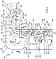
- eine ausschnittsweise Draufsicht auf eine elektrochemische Einheit einer mehrere längs einer Stapelrichtung aufeinanderfolgende elektrochemische Einheiten umfassenden elektrochemischen Vorrichtung, im Bereich einer Brenngaszufuhr und einer Kühlmittelzufuhr;
- Fig. 2
- einen Schnitt durch den Verbindungskanal zwischen einem Kühlmittel-Mediumkanal und einem Kühlmittel-Strömungsfeld der elektrochemischen Einheit aus
Fig. 1 , längs der Linie 2 - 2 inFig. 1 ; - Fig. 3
- einen weiteren Schnitt durch den Verbindungskanal zwischen dem Kühlmittel-Mediumkanal und dem Kühlmittel-Strömungsfeld der elektrochemischen Einheit aus
Fig. 1 , längs der Linie 3 - 3 inFig. 1 ; - Fig. 4
- einen Schnitt durch einen äußeren Randbereich der elektrochemischen Einheit aus
Fig. 1 im Bereich des Kühlmittel-Mediumkanals, längs der Linie 4 - 4 inFig. 1 ; - Fig. 5
- einen Schnitt durch einen Steg der elektrochemischen Einheit aus
Fig. 1 zwischen dem Brenngas-Mediumkanal und einem Oxidationsmittel-Mediumkanal, längs der Linie 5 - 5 inFig. 1 ; und - Fig. 6
- einen Schnitt durch einen mediumkanalseitigen Bereich eines Verbindungskanals zwischen dem Brenngas-Mediumkanal und dem Brenngas-Strömungsfeld der elektrochemischen Einheit aus
Fig. 1 , längs der Linie 6 - 6 inFig. 1 . - Gleiche oder funktional äquivalente Elemente sind in allen Figuren mit denselben Bezugszeichen bezeichnet.
- Eine in den
Fig. 1 bis 6 ausschnittsweise dargestellte, als Ganzes mit 100 bezeichnete elektrochemische Vorrichtung, beispielsweise ein Brennstoffzellenstapel oder ein Elektrolyseur, umfasst einen Stapel, der mehrere in einer Stapelrichtung 104 aufeinanderfolgende elektrochemische Einheiten 106, beispielsweise Brennstoffzelleneinheiten oder Elektrolyseeinheiten, und eine (nicht dargestellte) Spannvorrichtung zum Beaufschlagen der elektrochemischen Einheit mit einer längs der Stapelrichtung 104 gerichteten Spannkraft umfasst. - Wie am besten aus den
Fig. 2 und3 zu ersehen ist, umfasst jede elektrochemische Einheit 106 der elektrochemischen Vorrichtung 100 jeweils eine Bipolarplatte 108 und eine Membran-Elektroden-Anordnung (MEA) 110. - Die Membran-Elektroden-Anordnung 110 umfasst beispielsweise eine katalysatorbeschichtete Membran ("catalyst coated membrane"; CCM) und zwei Gasdiffusionslagen 112 und 114, wobei eine erste Gasdiffusionslage 112 anodenseitig und eine zweite Gasdiffusionslage 114 kathodenseitig angeordnet ist.
- Die Bipolarplatte 108 ist beispielsweise aus einem metallischen Material gebildet.
- Die Bipolarplatte 108 weist mehrere Medium-Durchtrittsöffnungen 116 auf, durch welche jeweils ein der elektrochemischen Vorrichtung 100 zuzuführendes fluides Medium (im Falle eines Brennstoffzellenstapels beispielsweise ein Brenngas, ein Oxidationsmittel oder ein Kühlmittel) durch die Bipolarplatte 108 hindurchtreten kann.
- Die Medium-Durchtrittsöffnungen 116 der im Stapel aufeinanderfolgenden Bipolarplatten 108 und die in der Stapelrichtung 104 zwischen den Medium-Durchtrittsöffnungen 116 liegenden Zwischenräume bilden zusammen jeweils einen Mediumkanal 118.
- Jedem Mediumkanal 118, durch welchen ein fluides Medium der elektrochemischen Vorrichtung 100 zuführbar ist, ist jeweils mindestens ein anderer Mediumkanal zugeordnet, durch welchen das betreffende fluide Medium aus der elektrochemischen Vorrichtung 100 abführbar ist.
- Durch ein dazwischen liegendes Strömungsfeld 120, welches vorzugsweise an einer Oberfläche einer benachbarten Bipolarplatte 108 oder (beispielsweise im Falle eines Kühlmittel-Strömungsfeldes) im Zwischenraum zwischen den Lagen einer mehrlagigen Bipolarplatte 108 ausgebildet ist, kann das Medium aus dem ersten Mediumkanal 118 quer, vorzugsweise im Wesentlichen senkrecht, zu der Stapelrichtung 104 zu dem zweiten Mediumkanal strömen.
- In
Fig. 1 ist beispielsweise ein Mediumkanal 122 für ein Kühlmittel der elektrochemischen Vorrichtung 100, ein Mediumkanal 124 für ein Brenngas der elektrochemischen Vorrichtung 100 und ein Mediumkanal 126 für ein Oxidationsmittel der elektrochemischen Vorrichtung 100 dargestellt. - Durch jeweils einen Verbindungskanal 128 steht jeder Mediumkanal 118 in Fluidverbindung mit dem jeweils zugeordneten Strömungsfeld 120.
- Jede Bipolarplatte 108 umfasst bei der in den Zeichnungen dargestellten Ausführungsform eine erste Lage 130 und eine zweite Lage 132, die längs (nicht dargestellter) Verbindungslinien, vorzugsweise stoffschlüssig, insbesondere durch Verschweißen, beispielsweise durch Laserschweißen, fluiddicht aneinander festgelegt sind.
- Wie aus
Fig. 1 zu ersehen ist, steht der Mediumkanal 122 für Kühlmittel über einen Verbindungskanal 134 für Kühlmittel, der durch einen Zwischenraum zwischen der ersten Lage 130 und der zweiten Lage 132 der Bipolarplatte 108 ausgebildet ist, in Fluidverbindung mit einem Strömungsfeld 136 für das Kühlmittel, welches im Zwischenraum zwischen der ersten Lage 130 und der zweiten Lage 132 der Bipolarplatte 108 ausgebildet ist. - Wie ferner aus
Fig. 1 zu ersehen ist, steht der Mediumkanal 124 für Brenngas über einen Verbindungskanal 138 für Brenngas in Fluidverbindung mit einem Strömungsfeld 140 für das Brenngas, welches zwischen der ersten Lage 126 der Bipolarplatte 108 und der ersten Gasdiffusionslage 112 ausgebildet ist. Um die Strömung der Medien durch die jeweils zugeordneten Strömungsfelder 120 zu führen, sind die erste Lage 130 und die zweite Lage 132 der Bipolarplatte 108 im Bereich der Strömungsfelder 120 mit (nicht dargestellten) Strömungsleitelementen versehen, welche beispielsweise in Form erhabener Sicken ausgebildet sein können. - Ein unerwünschtes Austreten der fluiden Medien aus den Mediumkanälen 118 und den Strömungsfeldern 120 der elektrochemischen Vorrichtung 100 wird durch eine Dichtungsanordnung 142 vermieden.
- Die Dichtungsanordnung 142 umfasst einen Strömungsfeld-Abschnitt 144 mit einer oder mehreren, im dargestellten Ausführungsbeispiel mit zwei, Dichtlinien 146, welche zwischen den Strömungsfeldern 120 einerseits und den Mediumkanälen 118 andererseits verlaufen und die Verbindungskanäle 128 queren, durch welche die Strömungsfelder 120 mit den jeweils zugeordneten Mediumkanälen 118 in Fluidverbindung stehen.
- Ferner umfasst die Dichtungsanordnung 142 Mediumkanal-Abschnitte 148 mit jeweils einer oder mehreren, im zeichnerisch dargestellten Ausführungsbeispiel mit jeweils zwei, Dichtlinien 150, welche jeweils einen der Mediumkanäle 118 zumindest abschnittsweise umgeben und den betreffenden Mediumkanal 118 von den Strömungsfeldern 120 und von einem äußeren Rand 152 der Bipolarplatte 108 trennen.
- Die Mediumkanal-Abschnitte 148 der Dichtungsanordnung 142 umfassen jeweils ein Dichtelement 154, welches zwischen einer ersten Lage 130 einer Bipolarplatte 108 und einer zweiten Lage 132 einer in der Stapelrichtung 104 benachbarten (nicht dargestellten) weiteren Bipolarplatte angeordnet ist und sich im Wesentlichen parallel zu dem Rand 156 einer Medium-Durchtrittsöffnung 116 des betreffenden Mediumkanals 118 erstreckt.
- Das Dichtelement 154 kann auf jeder Seite mit einer oder mehreren Dichtlippen 158 versehen sein.
- An seinem dem äußeren Rand 152 der Bipolarplatte 108 zugewandten Rand kann das Dichtelement 154 mit einem Blockbereich 160 versehen sein (siehe
Fig. 4 ). - Der Strömungsfeld-Abschnitt 144 der Dichtungsanordnung 142 umfasst vorzugsweise zwei Dichtelemente 162a und 162b, welche ebenfalls zwischen der ersten Lage 130 der Bipolarplatte 108 und der zweiten Lage 132 der benachbarten Bipolarplatte angeordnet sind.
- Dabei ist das erste Dichtelement 162a vorzugsweise an der (beispielsweise anodenseitigen) ersten Gasdiffusionslage 112 festgelegt und das zweite Dichtelement 162b vorzugsweise an der (beispielsweise kathodenseitigen) zweiten Gasdiffusionslage 114 der Membran-Elektroden-Anordnung 110 festgelegt.
- Beispielsweise kann vorgesehen sein, dass die Dichtelemente 162a und 162b an die jeweils zugeordnete Gasdiffusionslage 112 beziehungsweise 114 angespritzt oder angegossen sind.
- Dabei kann vorgesehen sein, dass das erste Dichtelement 162a eine oder mehrere Dichtlippen 164 aufweist, welche längs der Dichtlinien 146 an der ersten Lage 130 der Bipolarplatte 108 anliegen, und mit einer vorzugsweise im Wesentlichen ebenen Begrenzungsfläche 166 an einer ebenfalls, vorzugsweise im Wesentlichen ebenen, Begrenzungsfläche 168 des zweiten Dichtelements 162b anliegt, während das zweite Dichtelement 162b eine oder mehrere Dichtlippen 170 aufweist, mit denen das Dichtelement 162b längs der Dichtlinien 146 an der zweiten Lage 132 der benachbarten Bipolarplatte anliegt, und mit der, vorzugsweise im Wesentlichen ebenen, Begrenzungsfläche 168 an der Begrenzungsfläche 166 des ersten Dichtelements 162a anliegt.
- Eines der Dichtelemente 162a, 162b, vorzugsweise das zweite Dichtelement 162b, kann einstückig mit dem Dichtelement 154 mindestens eines der Mediumkanal-Abschnitte 148 der Dichtungsanordnung 142 ausgebildet sein.
- Die Dichtungsanordnung 142 kann somit zweiteilig ausgebildet sein, wobei ein erster Teil 172 der Dichtungsanordnung 142 das erste Dichtelement 162a des Strömungsfeld-Abschnitts 144 umfasst und vorzugsweise von der ersten Gasdiffusionslage 112 getragen ist und wobei ein zweiter Teil 174 der Dichtungsanordnung 142 das zweite Dichtelement 162b des Strömungsfeld-Abschnitts 144 und die Dichtelemente 154 der Mediumkanal-Abschnitte 148 umfasst und vorzugsweise von der zweiten Gasdiffusionslage 114 getragen ist.
- Da die erste Lage 130 und die zweite Lage 132 der Bipolarplatte 108 im Bereich eines Verbindungskanals 128 voneinander beabstandet sind (siehe insbesondere die
Fig. 2 ,3 und6 ), weisen die Dichtelemente 162a, 162b und das Dichtelement 154 in diesem Bereich der Dichtungsanordnung 142 eine Gesamthöhe h auf, welche geringer ist als die Gesamthöhe H der Dichtungsanordnung 142 außerhalb des Bereichs der Verbindungskanäle 128. Dabei entspricht die Gesamthöhe h beziehungsweise H der Summe der Einzelhöhen des ersten Teils 172 der Dichtungsanordnung 142 und des zweiten Teils 174 der Dichtungsanordnung 142. - Jeder Verbindungskanal 128 weist eine mediumkanalseitige Mündungsöffnung 176 auf, die sich längs einer Umfangsrichtung 178 des jeweils zugeordneten Strömungsfelds 120 von einem ersten mediumkanalseitigen Rand 180 bis zu einem zweiten mediumkanalseitigen Rand 182 erstreckt.
- Ferner weist jeder Verbindungskanal 128 eine strömungsfeldseitige Mündungsöffnung 184 auf, die sich längs der Umfangsrichtung 178 des Strömungsfelds 120 von einem ersten strömungsfeldseitigen Rand 186 bis zu einem zweiten strömungsfeldseitigen Rand 188 erstreckt.
- Wie aus
Fig. 1 zu ersehen ist, ist der erste strömungsfeldseitige Rand 186 der strömungsfeldseitigen Mündungsöffnung 184 des Verbindungskanals 134 für Kühlmittel bei der zeichnerisch dargestellten Ausführungsform gegenüber dem ersten mediumkanalseitigen Rand 180 der mediumkanalseitigen Mündungsöffnung 176 des Verbindungskanals 134 für Kühlmittel längs der Umfangsrichtung 178 des Strömungsfelds 120 von dem zweiten strömungsfeldseitigen Rand 182 der strömungsfeldseitigen Mündungsöffnung 184 des Verbindungskanals 134 für Kühlmittel weg versetzt, so dass die strömungsfeldseitige Mündungsöffnung 184 an ihrem ersten strömungsfeldseitigen Rand 186 längs der Umfangsrichtung 178 über den ersten mediumkanalseitigen Rand 180 der mediumkanalseitigen Mündungsöffnung 176 übersteht. - Ferner ist der zweite strömungsfeldseitige Rand 188 der strömungsfeldseitigen Mündungsöffnung 184 des Verbindungskanals 134 für Kühlmittel bei dieser Ausführungsform gegenüber dem zweiten mediumkanalseitigen Rand 182 der mediumkanalseitigen Mündungsöffnung 176 des Verbindungskanals 134 für Kühlmittel längs der Umfangsrichtung 178 des Strömungsfeldes 120 von dem ersten strömungsfeldseitigen Rand 186 der strömungsfeldseitigen Mündungsöffnung 184 weg versetzt, so dass die strömungsfeldseitige Mündungsöffnung 184 des Verbindungskanals 134 für Kühlmittel an ihrem zweiten strömungsfeldseitigen Rand 188 längs der Umfangsrichtung 178 des Strömungsfelds 120 über den zweiten mediumkanalseitigen Rand 182 der mediumkanalseitigen Mündungsöffnung 176 des Verbindungskanals 134 für Kühlmittel übersteht.
- Die strömungsfeldseitige Mündungsöffnung 184 des Verbindungskanals 134 für Kühlmittel weist daher eine größere Fluiddurchtrittsfläche auf als die mediumkanalseitige Mündungsöffnung 176 des Verbindungskanals 134 für Kühlmittel.
- Wie aus
Fig. 1 zu ersehen ist, mündet die strömungsfeldseitige Mündungsöffnung 184 des Verbindungskanals 134 für Kühlmittel an einem Eckbereich 190 des zugeordneten Strömungsfelds 120, nämlich des Strömungsfelds 136 für Kühlmittel. - Der erste mediumkanalseitige Rand 180 der mediumkanalseitigen Mündungsöffnung 176 des Verbindungskanals 134 für Kühlmittel ist mit dem ersten strömungsfeldseitigen Rand 186 der strömungsfeldseitigen Mündungsöffnung 184 des Verbindungskanals 134 für Kühlmittel durch eine erste Randlinie 192 verbunden, welche eine erste seitliche Begrenzung des Verbindungskanals 134 für Kühlmittel bildet.
- Der zweite mediumkanalseitige Rand 182 der mediumkanalseitigen Mündungsöffnung 176 des Verbindungskanals 134 für Kühlmittel ist mit dem zweiten strömungsfeldseitigen Rand 188 der strömungsfeldseitigen Mündungsöffnung 184 des Verbindungskanals 134 für Kühlmittel durch eine zweite Randlinie 194 verbunden, welche eine zweite seitliche Begrenzung des Verbindungskanals 134 für Kühlmittel bildet.
- Wie aus
Fig. 1 zu ersehen ist, sind sowohl die erste Randlinie 192 als auch die zweite Randlinie 194 jeweils gestuft ausgebildet. - Insbesondere umfasst die erste Randlinie 192 einen sich von dem ersten mediumkanalseitigen Rand 180 der mediumkanalseitigen Mündungsöffnung 176 des Verbindungskanals 134 für Kühlmittel im Wesentlichen senkrecht zur Umfangsrichtung 178 des Strömungsfelds 120 und senkrecht zur Stapelrichtung 104 weg erstreckenden ersten mediumkanalseitigen Randlinienabschnitt 196 und einen sich von dem ersten strömungsfeldseitigen Rand 186 der strömungsfeldseitigen Mündungsöffnung 184 des Verbindungskanals 134 für Kühlmittel im Wesentlichen senkrecht zur Umfangsrichtung 178 des Strömungsfelds 120 und senkrecht zur Stapelrichtung 104 weg erstreckenden ersten strömungsfeldseitigen Randlinienabschnitt 198.
- Der erste mediumkanalseitige Randlinienabschnitt 196 und der erste strömungsfeldseitige Randlinienabschnitt 198 sind durch einen sich im Wesentlichen parallel zur Umfangsrichtung 178 des Strömungsfelds 120 erstreckenden ersten zentralen Randlinienabschnitt 200 miteinander verbunden.
- Die zweite Randlinie 194 umfasst einen sich von dem zweiten mediumkanalseitigen Rand 182 der mediumkanalseitigen Mündungsöffnung 176 des Verbindungskanals 134 für Kühlmittel im Wesentlichen senkrecht zur Umfangsrichtung 178 des Strömungsfelds 120 und senkrecht zur Stapelrichtung 104 weg erstreckenden zweiten mediumkanalseitigen Randlinienabschnitt 202 und einen sich von dem zweiten strömungsfeldseitigen Rand 188 der strömungsfeldseitigen Mündungsöffnung 184 des Verbindungskanals 134 für Kühlmittel im Wesentlichen senkrecht zur Umfangsrichtung 178 des Strömungsfelds 120 und senkrecht zur Stapelrichtung 104 weg erstreckenden zweiten strömungsfeldseitigen Randlinienabschnitt 204.
- Der zweite mediumkanalseitige Randlinienabschnitt 202 ist mit dem zweiten strömungsfeldseitigen Randlinienabschnitt 204 durch einen sich im Wesentlichen parallel zu der Umfangsrichtung 178 des Strömungsfelds 120 erstreckenden zweiten zentralen Randlinienabschnitt 206 verbunden.
- Wie aus den
Fig. 2 ,3 und6 zu ersehen ist, liegen die beiden Lagen 130 und 132 der Bipolarplatte 108 längs einer Kontaktebene 208, welche senkrecht zur Stapelrichtung 104 ausgerichtet ist, aneinander an. - Beim zeichnerisch dargestellten Ausführungsbeispiel umfasst jede der Lagen 130, 132 der Bipolarplatte 108 jeweils einen an den ersten mediumkanalseitigen Rand 180 der mediumkanalseitigen Mündungsöffnung 176 des Verbindungskanals 134 für Kühlmittel angrenzenden ersten mediumkanalseitigen Rampenbereich 210, einen an den ersten strömungsfeldseitigen Rand 186 der strömungsfeldseitigen Mündungsöffnung 184 angrenzenden ersten strömungsfeldseitigen Rampenbereich 212, einen an den zweiten mediumkanalseitigen Rand 182 der mediumkanalseitigen Mündungsöffnung 176 des Verbindungskanals 134 für Kühlmittel angrenzenden zweiten mediumkanalseitigen Rampenbereich 214 und einen an den zweiten strömungsfeldseitigen Rand 188 der strömungsfeldseitigen Mündungsöffnung 184 des Verbindungskanals 134 für Kühlmittel angrenzenden zweiten strömungsfeldseitigen Rampenbereich 216.
- Dabei ist jeder der Rampenbereiche 210, 212, 214 und 216 vorzugsweise im Wesentlichen eben ausgebildet.
- Vorzugsweise ist jeder der Rampenbereiche 210, 212, 214 und 216 gegenüber der Kontaktebene 208 der Lagen 130, 132 der Bipolarplatte 108 um einen Winkel von vorzugsweise höchstens 45°, insbesondere höchstens ungefähr 30°, besonders bevorzugt höchstens ungefähr 20°, beispielsweise höchstens ungefähr 10°, geneigt.
- Ferner ist jeder der Rampenbereiche 210, 212, 214 und 216 gegenüber der Kontaktebene 208 der Lagen 130, 132 der Bipolarplatte 108 um einen Winkel von vorzugsweise mindestens ungefähr 2°, insbesondere von mindestens ungefähr 3°, geneigt.
- Dabei sind die Rampenbereiche 210, 212, 214 und 216 der ersten Lage 130 der Bipolarplatte 108 vorzugsweise bezüglich der Kontaktebene 208 im Wesentlichen spiegelsymmetrisch zu den Rampenbereichen 210, 212, 214 und 216 der zweiten Lage 132 der Bipolarplatte 108 angeordnet und ausgebildet.
- Wie ferner aus
Fig. 1 zu ersehen ist, ist der erste strömungsfeldseitige Rand 186 der strömungsfeldseitigen Mündungsöffnung 184 des Verbindungskanals 138 für Brenngas bei der zeichnerisch dargestellten Ausführungsform gegenüber dem ersten mediumkanalseitigen Rand 180 der mediumkanalseitigen Mündungsöffnung 176 des Verbindungskanals 138 für Brenngas nicht längs der Umfangsrichtung 178 des Strömungsfelds 120 versetzt, so dass die strömungsfeldseitige Mündungsöffnung 184 an ihrem ersten strömungsfeldseitigen Rand 186 an derselben Position bezüglich der Umfangsrichtung 178 des Strömungsfelds 120 endet wie die mediumkanalseitige Mündungsöffnung 176. - Der zweite strömungsfeldseitige Rand 188 der strömungsfeldseitigen Mündungsöffnung 184 des Verbindungskanals 138 für Brenngas ist bei dieser Ausführungsform gegenüber dem zweiten mediumkanalseitigen Rand 182 der mediumkanalseitigen Mündungsöffnung 176 des Verbindungskanals 138 für Brenngas längs der Umfangsrichtung 178 des Strömungsfeldes 120 von dem ersten strömungsfeldseitigen Rand 186 der strömungsfeldseitigen Mündungsöffnung 184 weg versetzt, so dass die strömungsfeldseitige Mündungsöffnung 184 des Verbindungskanals 138 für Brenngas an ihrem zweiten strömungsfeldseitigen Rand 188 längs der Umfangsrichtung 178 des Strömungsfelds 120 über den zweiten mediumkanalseitigen Rand 182 der mediumkanalseitigen Mündungsöffnung 176 des Verbindungskanals 138 für Brenngas übersteht.
- Die strömungsfeldseitige Mündungsöffnung 184 des Verbindungskanals 138 für Brenngas weist daher eine größere Fluiddurchtrittsfläche auf als die mediumkanalseitige Mündungsöffnung 176 des Verbindungskanals 138 für Brenngas.
- Der erste mediumkanalseitige Rand 180 der mediumkanalseitigen Mündungsöffnung 176 des Verbindungskanals 138 für Brenngas ist mit dem ersten strömungsfeldseitigen Rand 186 der strömungsfeldseitigen Mündungsöffnung 184 des Verbindungskanals 138 für Brenngas durch eine erste Randlinie 192 verbunden, welche eine erste seitliche Begrenzung des Verbindungskanals 138 für Brenngas bildet.
- Der zweite mediumkanalseitige Rand 182 der mediumkanalseitigen Mündungsöffnung 176 des Verbindungskanals 138 für Brenngas ist mit dem zweiten strömungsfeldseitigen Rand 188 der strömungsfeldseitigen Mündungsöffnung 184 des Verbindungskanals 138 für Brenngas durch eine zweite Randlinie 194 verbunden, welche eine zweite seitliche Begrenzung des Verbindungskanals 138 für Brenngas bildet.
- Wie aus
Fig. 1 zu ersehen ist, ist die erste Randlinie 192 des Verbindungskanals 138 für Brenngas im Wesentlichen geradlinig ausgebildet. - Wie aus
Fig. 1 ferner zu ersehen ist, ist die zweite Randlinie 194 des Verbindungskanals 138 für Brenngas gestuft ausgebildet. - Die erste Randlinie 192 des Verbindungskanals 138 für Brenngas umfasst einen sich von dem ersten mediumkanalseitigen Rand 180 der mediumkanalseitigen Mündungsöffnung 176 im Wesentlichen senkrecht zur Umfangsrichtung 178 des Strömungsfelds 120 und senkrecht zur Stapelrichtung 104 weg erstreckenden ersten mediumkanalseitigen Randlinienabschnitt 196 und einen sich von dem ersten strömungsfeldseitigen Rand 186 der strömungsfeldseitigen Mündungsöffnung 184 des Verbindungskanals 138 für Brenngas im Wesentlichen senkrecht zur Umfangsrichtung 178 des Strömungsfelds 120 und senkrecht zur Stapelrichtung 104 weg erstreckenden ersten strömungsfeldseitigen Randlinienabschnitt 198.
- Der erste mediumkanalseitige Randlinienabschnitt 196 und der erste strömungsfeldseitige Randlinienabschnitt 198 sind im Wesentlichen miteinander fluchtend ausgebildet.
- Die zweite Randlinie 194 des Verbindungskanals 138 für Brenngas umfasst einen sich von dem zweiten mediumkanalseitigen Rand 182 der mediumkanalseitigen Mündungsöffnung 176 des Verbindungskanals 138 für Brenngas im Wesentlichen senkrecht zur Umfangsrichtung 178 des Strömungsfelds 120 und senkrecht zur Stapelrichtung 104 weg erstreckenden zweiten mediumkanalseitigen Randlinienabschnitt 202 und einen sich von dem zweiten strömungsfeldseitigen Rand 188 der strömungsfeldseitigen Mündungsöffnung 184 des Verbindungskanals 138 für Brenngas im Wesentlichen senkrecht zur Umfangsrichtung 178 des Strömungsfelds 120 und senkrecht zur Stapelrichtung 104 weg erstreckenden zweiten strömungsfeldseitigen Randlinienabschnitt 204.
- Der zweite mediumkanalseitige Randlinienabschnitt 202 ist mit dem zweiten strömungsfeldseitigen Randlinienabschnitt 204 durch einen sich im Wesentlichen parallel zu der Umfangsrichtung 178 des Strömungsfelds 120 erstreckenden zweiten zentralen Randlinienabschnitt 206 verbunden.
- Beim zeichnerisch dargestellten Ausführungsbeispiel umfasst jede der Lagen 130, 132 der Bipolarplatte 108 jeweils einen an den ersten mediumkanalseitigen Rand 180 der mediumkanalseitigen Mündungsöffnung 176 des Verbindungskanals 138 für Brenngas angrenzenden ersten mediumkanalseitigen Rampenbereich 210, einen an den ersten strömungsfeldseitigen Rand 186 der strömungsfeldseitigen Mündungsöffnung 184 des Verbindungskanals 138 für Brenngas angrenzenden ersten strömungsfeldseitigen Rampenbereich 212, einen an den zweiten mediumkanalseitigen Rand 182 der mediumkanalseitigen Mündungsöffnung 176 des Verbindungskanals 138 für Brenngas angrenzenden zweiten mediumkanalseitigen Rampenbereich 214 und einen an den zweiten strömungsfeldseitigen Rand 188 der strömungsfeldseitigen Mündungsöffnung 184 des Verbindungskanals 138 für Brenngas angrenzenden zweiten strömungsfeldseitigen Rampenbereich 216.
- Dabei ist jeder der Rampenbereiche 210, 212, 214 und 216 der Lagen 130, 132 der Bipolarplatte 108 im Bereich des Verbindungskanals 138 für Brenngas vorzugsweise im Wesentlichen eben ausgebildet.
- Wie aus
Fig. 6 zu ersehen ist, ist vorzugsweise jeder der Rampenbereiche 210, 212, 214 und 216 des Verbindungskanals 138 für Brenngas gegenüber der Kontaktebene 208 der Lagen 130, 132 der Bipolarplatte 108 um einen spitzen Winkel α von vorzugsweise höchstens 45°, insbesondere höchstens ungefähr 30°, besonders bevorzugt höchstens ungefähr 20°, beispielsweise höchstens ungefähr 10°, geneigt. - Ferner ist jeder der Rampenbereiche 210, 212, 214 und 216 im Bereich des Verbindungskanals 138 für Brenngas gegenüber der Kontaktebene 208 der Lagen 130, 132 der Bipolarplatte 108 um einen spitzen Winkel α von vorzugsweise mindestens ungefähr 2°, insbesondere von mindestens ungefähr 3°, geneigt.
- Dabei sind die Rampenbereiche 210, 212, 214 und 216 der ersten Lage 130 der Bipolarplatte 108 vorzugsweise bezüglich der Kontaktebene 208 im Wesentlichen spiegelsymmetrisch zu den Rampenbereichen 210, 212, 214 und 216 der zweiten Lage 132 der Bipolarplatte 108 angeordnet und ausgebildet.
- Bei der zeichnerisch dargestellten Ausführungsform einer elektrochemischen Vorrichtung 100 bleibt der Abstand zwischen den beiden Lagen 130 und 132 der Bipolarplatte 108, welche einen Verbindungskanal 128 begrenzen, auch dann erhalten, wenn die elektrochemischen Einheiten 106 der elektrochemischen Vorrichtung 100 in der Stapelrichtung 104 gegeneinander verspannt werden, weil ein oder vorzugsweise mehrere Abstützelemente 218 im jeweiligen Verbindungskanal 128 zwischen den zwei Lagen 130 und 132 der Bipolarplatte 108 angeordnet sind.
- Insbesondere kann vorgesehen sein, dass ein solches Abstützelement 218 einen Abstützbereich 220a der ersten Lage 130 der Bipolarplatte 108 umfasst, welcher zu der zweiten Lage 132 der Bipolarplatte 108 hin vorspringt, und/oder einen Abstützbereich 210b der zweiten Lage 132 der Bipolarplatte 108 umfasst, welcher zu der ersten Lage 130 der Bipolarplatte 108 hin vorspringt.
- Vorzugsweise umfasst ein solches Abstützelement 218 einen an der ersten Lage 130 der Bipolarplatte 108 vorgesehenen Abstützbereich 220a und einen an der zweiten Lage 132 der Bipolarplatte 108 vorgesehenen Abstützbereich 220b.
- Dabei liegen die Abstützbereiche 220a, 220b aneinander an, vorzugweise an einer im Wesentlichen parallel zu der Kontaktebene 208 der Bipolarplatte 108 ausgerichteten Abstützfläche 222, so dass die Abstützbereiche 220a, 220b sich aneinander abstützen.
- Die Abstützbereiche 220a, 220b können beispielsweise in Form von Noppen, Näpfen oder Stegen ausgebildet sein.
- Die Abstützbereiche 220a, 220b sind vorzugsweise einstückig mit jeweils einer der beiden abgestützten Lagen 130, 132 der Bipolarplatte 108 ausgebildet und vorzugsweise durch einen Umformvorgang, insbesondere einen Präge- oder Tiefziehvorgang, an der jeweiligen Lage 130 oder 132 ausgebildet.
- Das den Verbindungskanal 128 durchströmende fluide Medium strömt vorzugsweise seitlich an den Abstützelementen 218 vorbei.
- Wie am besten aus
Fig. 1 zu ersehen ist, können in einem Verbindungskanal 128, beispielsweise im Verbindungskanal 134 für Kühlmittel oder im Verbindungskanal 138 für Brenngas, eine oder mehrere Reihen 224 von Abstützelementen 218 vorgesehen sein, wobei jede Reihe 224 von Abstützelementen 218 mehrere längs der Umfangsrichtung 178 des jeweils zugeordneten Strömungsfelds 120 aufeinanderfolgende und längs der Umfangsrichtung 178 voneinander beabstandete Abstützelemente 218 umfasst. - Insbesondere kann vorgesehen sein, dass im Bereich eines Verbindungskanals 128 eine mediumkanalseitige Reihe 226 von Abstützelementen 218 vorgesehen ist, welche im Bereich der mediumkanalseitigen Mündungsöffnung 176 des Verbindungskanals 128 angeordnet sind und die mediumkanalseitige Mündungsöffnung 176 in längs der Umfangsrichtung 178 aufeinander folgende Teil-Mündungsöffnungen unterteilen.
- Ferner kann im Bereich eines Verbindungskanals 128 eine strömungsfeldseitige Reihe 228 von Abstützelementen 218 vorgesehen sein, welche an der strömungsfeldseitigen Mündungsöffnung 184 des Verbindungskanals 128 angeordnet sind und die strömungsfeldseitige Mündungsöffnung 184 in längs der Umfangsrichtung 178 aufeinander folgende Teil-Mündungsöffnungen unterteilen.
- Ferner kann im Bereich eines Verbindungskanals 128 eine zentrale Reihe 230 von Abstützelementen 218 vorgesehen sein, welche zwischen der mediumkanalseitigen Mündungsöffnung 176 und der strömungsfeldseitigen Mündungsöffnung 184 des Verbindungskanals 128 angeordnet sind, längs der Umfangsrichtung 178 des Strömungsfelds 120 aufeinanderfolgen und längs der Umfangsrichtung 178 des Strömungsfeld 120 voneinander beabstandet sind.
- Vorzugsweise weisen alle Abstützelemente 218 der zentralen Reihe 230 von Abstützelementen 218 im Wesentlichen denselben Abstand von der mediumkanalseitigen Mündungsöffnung 176 des Verbindungskanals 128 auf.
- Ferner weisen vorzugsweise alle Abstützelemente 218 der zentralen Reihe 230 von Abstützelementen 218 im Wesentlichen denselben Abstand von der strömungsfeldseitigen Mündungsöffnung 184 des Verbindungskanals 128 auf.
- Dabei kann der Abstand der Abstützelemente 218 der zentralen Reihe 230 von Abstützelementen 218 von der mediumkanalseitigen Mündungsöffnung 176 im Wesentlichen gleich groß sein wie der Abstand der Abstützelemente 218 der zentralen Reihe 230 von Abstützelementen 218 von der strömungsfeldseitigen Mündungsöffnung 184; der Abstand der Abstützelemente 218 der zentralen Reihe 230 von Abstützelementen 218 von der mediumkanalseitigen Mündungsöffnung 176 kann aber auch größer oder kleiner sein als der Abstand der Abstützelemente 218 der zentralen Reihe 230 von Abstützelementen 218 von der strömungsfeldseitigen Mündungsöffnung 184.
- Die Abstützelemente 218 der verschiedenen Reihen 224 von Abstützelementen 218 können im Wesentlichen dieselbe Größe oder unterschiedliche Größen aufweisen.
- Wie am besten aus
Fig. 1 zu ersehen ist, kann insbesondere vorgesehen sein, dass die Abstützelemente 218 der mediumkanalseitigen Reihe 226 von Abstützelementen 218 einen kleineren (senkrecht zur Stapelrichtung 104 genommenen) Querschnitt aufweisen als die Abstützelemente 218 der zentralen Reihe 230 von Abstützelementen 218 und/oder als die Abstützelemente 218 der strömungsfeldseitigen Reihe 228 von Abstützelementen 218. - Die Abstützelemente 218 der zentralen Reihe 230 von Abstützelementen 218 weisen vorzugsweise einen (senkrecht zur Stapelrichtung 104 genommenen) Querschnitt auf, welcher größer ist als der (senkrecht zur Stapelrichtung 104 genommene) Querschnitt der Abstützelemente 218 der mediumkanalseitigen Reihe 226 von Abstützelementen 218 und/oder kleiner ist als der (senkrecht zur Stapelrichtung 104 genommene) Querschnitt der Abstützelemente 218 der strömungsfeldseitigen Reihe 228 von Abstützelementen 218.
- Die Abstützelemente 218 der strömungsfeldseitigen Reihe 228 von Abstützelementen 218 weisen vorzugsweise einen (senkrecht zur Stapelrichtung 104 genommenen) Querschnitt auf, welcher größer ist als der (senkrecht zur Stapelrichtung 104 genommene) Querschnitt der Abstützelement 218 der mediumkanalseitigen Reihe 226 von Abstützelementen 218 und/oder größer ist als der (senkrecht zur Stapelrichtung 104 genommene) Querschnitt der Abstützelemente 218 der zentralen Reihe 230 von Abstützelementen 218.
- Durch die den Verbindungskanal 128 abstützenden Abstützelemente 218 ist der Verbindungskanal 128 in der Stapelrichtung 104 stabilisiert, so dass die strömungsfeldseitige Mündungsöffnung 184 des Verbindungskanals 128 und/oder die mediumkanalseitige Mündungsöffnung 176 des Verbindungskanals 128 vergrößert werden kann und somit ein größerer Volumenstrom von fluidem Medium durch den Verbindungskanal 128 erzielt werden kann.
- Hierdurch kann der Druckverlust beim Durchströmen des Verbindungskanals 128 reduziert werden.
Claims (8)
- Elektrochemische Vorrichtung, umfassendeinen Stapel aus mehreren, längs einer Stapelrichtung (104) aufeinander folgenden elektrochemischen Einheiten (106), die jeweils eine elektrochemisch aktive Membran-Elektroden-Anordnung (110), eine Bipolarplatte (108) und eine Dichtungsanordnung (142) umfassen,mindestens einen Mediumkanal (118), der sich längs der Stapelrichtung (104) durch mehrere der elektrochemischen Einheiten (106) hindurch erstreckt,mindestens ein Strömungsfeld (120), durch welches ein Medium aus dem Mediumkanal (118) quer zu der Stapelrichtung (104) von dem Mediumkanal (118) zu einem anderen Mediumkanal strömen kann, und mindestens einen Verbindungskanal (128), durch welchen das Strömungsfeld (120) und der Mediumkanal (118) in Fluidverbindung miteinander stehen,wobei der Verbindungskanal (128) eine mediumkanalseitige Mündungsöffnung (176), die sich längs einer Umfangsrichtung (178) des Strömungsfelds (120) von einem ersten mediumkanalseitigen Rand (180) bis zu einem zweiten mediumkanalseitigen Rand (182) erstreckt, undeine strömungsfeldseitige Mündungsöffnung (184), die sich längs der Umfangsrichtung (178) des Strömungsfelds (120) von einem ersten strömungsfeldseitigen Rand (186) bis zu einem zweiten strömungsfeldseitigen Rand (188) erstreckt, aufweist,wobei der erste strömungsfeldseitige Rand (186) der strömungsfeldseitigen Mündungsöffnung (184) gegenüber dem ersten mediumkanalseitigen Rand (180) der mediumkanalseitigen Mündungsöffnung (176) längs der Umfangsrichtung (178) des Strömungsfelds (120) von dem zweiten strömungsfeldseitigen Rand (188) der strömungsfeldseitigen Mündungsöffnung (184) weg versetzt ist
und/oderder zweite strömungsfeldseitige Rand (188) der strömungsfeldseitigen Mündungsöffnung (184) gegenüber dem zweiten mediumkanalseitigen Rand (182) der mediumkanalseitigen Mündungsöffnung (176) längs der Umfangsrichtung (178) des Strömungsfelds (120) von dem ersten strömungsfeldseitigen Rand (186) der strömungsfeldseitigen Mündungsöffnung (184) weg versetzt ist,wobei der erste mediumkanalseitige Rand (180) der mediumkanalseitigen Mündungsöffnung (176) mit dem ersten strömungsfeldseitigen Rand (186) der strömungsfeldseitigen Mündungsöffnung (184) durch eine erste Randlinie (192) verbunden ist, welche eine erste seitliche Begrenzung des Verbindungskanals (128) bildet, und der zweite mediumkanalseitige Rand (182) der mediumkanalseitigen Mündungsöffnung (176) mit dem zweiten strömungsfeldseitigen Rand (188) der strömungsfeldseitigen Mündungsöffnung (184) durch eine zweite Randlinie (194) verbunden ist, welche eine zweite seitliche Begrenzung des Verbindungskanals (128) bildet, undwobei die erste Randlinie (192) einen sich von dem ersten mediumkanalseitigen Rand (180) der mediumkanalseitigen Mündungsöffnung (176) im Wesentlichen senkrecht zu der Umfangsrichtung (178) des Strömungsfelds (120) weg erstreckenden ersten mediumkanalseitigen Randlinienabschnitt (196) und einen sich von dem ersten strömungsfeldseitigen Rand (186) der strömungsfeldseitigen Mündungsöffnung (184) im Wesentlichen senkrecht zu der Umfangsrichtung (178) des Strömungsfelds (120) weg erstreckenden ersten strömungsfeldseitigen Randlinienabschnitt (198) umfasst
und/oderdie zweite Randlinie (194) einen sich von dem zweiten mediumkanalseitigen Rand (182) der mediumkanalseitigen Mündungsöffnung (176) im Wesentlichen senkrecht zu der Umfangsrichtung (178) des Strömungsfelds (120) weg erstreckenden zweiten mediumkanalseitigen Randlinienabschnitt (202) und einen sich von dem zweiten strömungsfeldseitigen Rand (188) der strömungsfeldseitigen Mündungsöffnung (184) im Wesentlichen senkrecht zu der Umfangsrichtung (178) des Strömungsfelds (120) weg erstreckenden zweiten strömungsfeldseitigen Randlinienabschnitt (204) umfasst,dadurch gekennzeichnet,dass die strömungsfeldseitige Mündungsöffnung (184) des Verbindungskanals (128) eine größere Fluiddurchtrittsfläche aufweist als die mediumkanalseitige Mündungsöffnung (176) des Verbindungskanals (128). - Elektrochemische Vorrichtung nach Anspruch 1, dadurch gekennzeichnet, dass die strömungsfeldseitige Mündungsöffnung (184) des Verbindungskanals (128) an einem Eckbereich (190) des Strömungsfelds (120) mündet.
- Elektrochemische Vorrichtung nach einem der Ansprüche 1 oder 2, dadurch gekennzeichnet, dass die erste Randlinie (192) und/oder die zweite Randlinie (194) gestuft ausgebildet ist.
- Elektrochemische Vorrichtung nach Anspruch 3, dadurch gekennzeichnet, dass der durchströmbare Querschnitt des Verbindungskanals (128) sich längs der Durchströmungsrichtung sprunghaft verändert.
- Elektrochemische Vorrichtung nach einem der Ansprüche 1 bis 4, dadurch gekennzeichnet, dass die Bipolarplatte (108) zwei Lagen (130, 132) umfasst, die im Bereich der mediumkanalseitigen Mündungsöffnung (176) und der strömungsfeldseitigen Mündungsöffnung (184) des Verbindungskanals (128) zumindest abschnittsweise voneinander beabstandet sind.
- Elektrochemische Vorrichtung nach Anspruch 5, dadurch gekennzeichnet, dass die Lagen (130, 132) der Bipolarplatte (108) längs einer Kontaktebene (208) aneinander anliegen und dass mindestens eine der Lagen (130, 132) einen an den ersten mediumkanalseitigen Rand (180) der mediumkanalseitigen Mündungsöffnung (176) angrenzenden ersten mediumkanalseitigen Rampenbereich (210),einen an den ersten strömungsfeldseitigen Rand (186) der strömungsfeldseitigen Mündungsöffnung (184) angrenzenden ersten strömungsfeldseitigen Rampenbereich (212),einen an den zweiten mediumkanalseitigen Rand (182) der mediumkanalseitigen Mündungsöffnung (176) angrenzenden zweiten mediumkanalseitigen Rampenbereich (214)
und/odereinen an den zweiten strömungsfeldseitigen Rand (188) der strömungsfeldseitigen Mündungsöffnung (184) angrenzenden zweiten strömungsfeldseitigen Rampenbereich (216) aufweist,wobei der jeweilige Rampenbereich (210, 212, 214, 216) gegenüber der Kontaktebene (208) geneigt ist. - Elektrochemische Vorrichtung nach Anspruch 6, dadurch gekennzeichnet, dass eine Lage (130) der Bipolarplatte (108) mindestens einen gegenüber der Kontaktebene (208) geneigten Rampenbereich (210, 212, 214, 216) aufweist, welcher an denselben Rand (180, 186, 182, 188) einer Mündungsöffnung (176, 184) des Verbindungskanals (128) angrenzt wie ein gegenüber der Kontaktebene (208) geneigter Rampenbereich (210, 212, 214, 216) der anderen Lage (132) der Bipolarplatte (108).
- Elektrochemische Vorrichtung nach einem der Ansprüche 5 bis 7, dadurch gekennzeichnet, dass mindestens ein Abstützelement (218) in dem Verbindungskanal (128) zwischen den zwei Lagen (130, 132) der Bipolarplatte (108) angeordnet ist.
Priority Applications (1)
| Application Number | Priority Date | Filing Date | Title |
|---|---|---|---|
| EP25176178.9A EP4576281A3 (de) | 2018-02-23 | 2019-02-08 | Medienzufuhrstruktur für elektrochemische vorrichtung |
Applications Claiming Priority (2)
| Application Number | Priority Date | Filing Date | Title |
|---|---|---|---|
| DE102018104172.1A DE102018104172A1 (de) | 2018-02-23 | 2018-02-23 | Elektrochemische Vorrichtung |
| PCT/EP2019/053112 WO2019162106A1 (de) | 2018-02-23 | 2019-02-08 | Medienzufuhrstruktur für elektrochemische vorrichtung |
Related Child Applications (2)
| Application Number | Title | Priority Date | Filing Date |
|---|---|---|---|
| EP25176178.9A Division EP4576281A3 (de) | 2018-02-23 | 2019-02-08 | Medienzufuhrstruktur für elektrochemische vorrichtung |
| EP25176178.9A Division-Into EP4576281A3 (de) | 2018-02-23 | 2019-02-08 | Medienzufuhrstruktur für elektrochemische vorrichtung |
Publications (2)
| Publication Number | Publication Date |
|---|---|
| EP3756231A1 EP3756231A1 (de) | 2020-12-30 |
| EP3756231B1 true EP3756231B1 (de) | 2025-06-25 |
Family
ID=65433646
Family Applications (2)
| Application Number | Title | Priority Date | Filing Date |
|---|---|---|---|
| EP19705305.1A Active EP3756231B1 (de) | 2018-02-23 | 2019-02-08 | Medienzufuhrstruktur für elektrochemische vorrichtung |
| EP25176178.9A Pending EP4576281A3 (de) | 2018-02-23 | 2019-02-08 | Medienzufuhrstruktur für elektrochemische vorrichtung |
Family Applications After (1)
| Application Number | Title | Priority Date | Filing Date |
|---|---|---|---|
| EP25176178.9A Pending EP4576281A3 (de) | 2018-02-23 | 2019-02-08 | Medienzufuhrstruktur für elektrochemische vorrichtung |
Country Status (5)
| Country | Link |
|---|---|
| US (1) | US12057607B2 (de) |
| EP (2) | EP3756231B1 (de) |
| CN (1) | CN111727523A (de) |
| DE (1) | DE102018104172A1 (de) |
| WO (1) | WO2019162106A1 (de) |
Families Citing this family (2)
| Publication number | Priority date | Publication date | Assignee | Title |
|---|---|---|---|---|
| DE102022126790A1 (de) * | 2022-10-13 | 2024-04-18 | Ekpo Fuel Cell Technologies Gmbh | Elektrochemische Vorrichtung |
| DE102023207321A1 (de) * | 2023-08-01 | 2025-02-06 | Robert Bosch Gesellschaft mit beschränkter Haftung | Elektrolysezellensystem |
Family Cites Families (4)
| Publication number | Priority date | Publication date | Assignee | Title |
|---|---|---|---|---|
| DE10323646B4 (de) * | 2003-05-26 | 2012-09-20 | Daimler Ag | Bipolarplatte für eine Brennstoffzellenanordnung |
| DE102013210542A1 (de) * | 2013-06-06 | 2014-12-11 | Volkswagen Ag | Bipolarplatte, Brennstoffzelle mit einer solchen und Kraftfahrzeug mit einer solchen Brennstoffzelle |
| DE102014104017A1 (de) * | 2014-03-24 | 2015-09-24 | Elringklinger Ag | Elektrochemische Vorrichtung |
| DE202015104972U1 (de) | 2015-09-18 | 2016-12-20 | Reinz-Dichtungs-Gmbh | Separatorplatte für ein elektrochemisches System |
-
2018
- 2018-02-23 DE DE102018104172.1A patent/DE102018104172A1/de active Pending
-
2019
- 2019-02-08 WO PCT/EP2019/053112 patent/WO2019162106A1/de not_active Ceased
- 2019-02-08 CN CN201980013753.7A patent/CN111727523A/zh active Pending
- 2019-02-08 EP EP19705305.1A patent/EP3756231B1/de active Active
- 2019-02-08 EP EP25176178.9A patent/EP4576281A3/de active Pending
-
2020
- 2020-08-21 US US16/999,203 patent/US12057607B2/en active Active
Also Published As
| Publication number | Publication date |
|---|---|
| WO2019162106A1 (de) | 2019-08-29 |
| US12057607B2 (en) | 2024-08-06 |
| EP4576281A2 (de) | 2025-06-25 |
| US20200381748A1 (en) | 2020-12-03 |
| EP4576281A3 (de) | 2025-09-03 |
| CN111727523A (zh) | 2020-09-29 |
| DE102018104172A1 (de) | 2019-08-29 |
| EP3756231A1 (de) | 2020-12-30 |
Similar Documents
| Publication | Publication Date | Title |
|---|---|---|
| DE102005057045B4 (de) | Bipolarplatte und deren Verwendung in einer Brennstoffzelleneinheit | |
| DE112007002407B4 (de) | Brennstoffzelle | |
| WO2018220065A1 (de) | Separatorplatte für ein elektrochemisches system | |
| EP3577708B1 (de) | Bipolarplatte mit verbesserter strömungsverteilung für eine brennstoffzelle | |
| DE202018103058U1 (de) | Separatorplatte für ein elektrochemisches System | |
| EP4566105A2 (de) | Bipolarplatte für eine elektrochemische einheit einer elektrochemischen vorrichtung und elektrochemische vorrichtung | |
| DE102022119209A1 (de) | Bipolarplatte für eine elektrochemische Einheit einer elektrochemischen Vorrichtung und elektrochemische Vorrichtung | |
| EP3756231B1 (de) | Medienzufuhrstruktur für elektrochemische vorrichtung | |
| WO2024028095A2 (de) | Verfahren zum stoffschlüssigen verbinden einer ersten bipolarplattenlage und einer zweiten bipolarplattenlage, bipolarplatte für eine elektrochemische einheit einer elektrochemischen vorrichtung und elektrochemische vorrichtung | |
| DE3516766A1 (de) | Brennstoffzelle | |
| DE102021134038A1 (de) | Verfahren zur Herstellung einer Bipolarplattenlage für eine Bipolarplatte einer elektrochemischen Einheit, Bipolarplattenlage für eine Bipolarplatte einer elektrochemischen Einheit und elektrochemische Einheit für eine elektrochemische Vorrichtung | |
| DE102022122717B3 (de) | Bipolarplatte und elektrochemische Zelle | |
| DE102022203540A1 (de) | Separatorplatte mit homogenisierter sickenkraft im portbereich | |
| DE102005057044B4 (de) | Bipolarplatte und deren Verwendung | |
| EP4128401B1 (de) | Bipolarplatte für eine elektrochemische vorrichtung | |
| DE202023105128U1 (de) | Bipolarplatte mit mindestens einer Lage und mindestens einem Einlegeteil | |
| DE10323646A1 (de) | Bipolarplatte für eine Brennstoffzellenanordnung | |
| DE102022208625A1 (de) | Separatorplatte und elektrochemische Zelle | |
| DE102023207321A1 (de) | Elektrolysezellensystem | |
| EP4566104A1 (de) | Bipolarplatte für eine elektrochemische einheit einer elektrochemischen vorrichtung und elektrochemische vorrichtung | |
| DE10107789A1 (de) | Brennstoffzelle | |
| WO2022263492A1 (de) | Strömungselement, bipolarplatte und brennstoffzelleneinrichtung | |
| DE102024130749A1 (de) | Bipolarplatte und eine Bipolarplatte umfassende elektrochemische Vorrichtung | |
| EP4293761A1 (de) | Fluidströmungsführung für das führen eines strömenden fluids und verwendungen für die fluidströmungsführung | |
| DE102024114370A1 (de) | Bipolarplatte und Brennstoffzellenvorrichtung mit einer Bipolarplatte |
Legal Events
| Date | Code | Title | Description |
|---|---|---|---|
| STAA | Information on the status of an ep patent application or granted ep patent |
Free format text: STATUS: UNKNOWN |
|
| STAA | Information on the status of an ep patent application or granted ep patent |
Free format text: STATUS: THE INTERNATIONAL PUBLICATION HAS BEEN MADE |
|
| PUAI | Public reference made under article 153(3) epc to a published international application that has entered the european phase |
Free format text: ORIGINAL CODE: 0009012 |
|
| STAA | Information on the status of an ep patent application or granted ep patent |
Free format text: STATUS: REQUEST FOR EXAMINATION WAS MADE |
|
| 17P | Request for examination filed |
Effective date: 20200820 |
|
| AK | Designated contracting states |
Kind code of ref document: A1 Designated state(s): AL AT BE BG CH CY CZ DE DK EE ES FI FR GB GR HR HU IE IS IT LI LT LU LV MC MK MT NL NO PL PT RO RS SE SI SK SM TR |
|
| AX | Request for extension of the european patent |
Extension state: BA ME |
|
| DAV | Request for validation of the european patent (deleted) | ||
| DAX | Request for extension of the european patent (deleted) | ||
| RAP1 | Party data changed (applicant data changed or rights of an application transferred) |
Owner name: EKPO FUEL CELL TECHNOLOGIES GMBH |
|
| P01 | Opt-out of the competence of the unified patent court (upc) registered |
Effective date: 20230519 |
|
| GRAP | Despatch of communication of intention to grant a patent |
Free format text: ORIGINAL CODE: EPIDOSNIGR1 |
|
| STAA | Information on the status of an ep patent application or granted ep patent |
Free format text: STATUS: GRANT OF PATENT IS INTENDED |
|
| INTG | Intention to grant announced |
Effective date: 20250115 |
|
| GRAS | Grant fee paid |
Free format text: ORIGINAL CODE: EPIDOSNIGR3 |
|
| GRAA | (expected) grant |
Free format text: ORIGINAL CODE: 0009210 |
|
| STAA | Information on the status of an ep patent application or granted ep patent |
Free format text: STATUS: THE PATENT HAS BEEN GRANTED |
|
| AK | Designated contracting states |
Kind code of ref document: B1 Designated state(s): AL AT BE BG CH CY CZ DE DK EE ES FI FR GB GR HR HU IE IS IT LI LT LU LV MC MK MT NL NO PL PT RO RS SE SI SK SM TR |
|
| REG | Reference to a national code |
Ref country code: GB Ref legal event code: FG4D Free format text: NOT ENGLISH |
|
| REG | Reference to a national code |
Ref country code: CH Ref legal event code: EP |
|
| REG | Reference to a national code |
Ref country code: DE Ref legal event code: R096 Ref document number: 502019013504 Country of ref document: DE |
|
| REG | Reference to a national code |
Ref country code: CH Ref legal event code: EP |
|
| REG | Reference to a national code |
Ref country code: IE Ref legal event code: FG4D Free format text: LANGUAGE OF EP DOCUMENT: GERMAN |
|
| PG25 | Lapsed in a contracting state [announced via postgrant information from national office to epo] |
Ref country code: FI Free format text: LAPSE BECAUSE OF FAILURE TO SUBMIT A TRANSLATION OF THE DESCRIPTION OR TO PAY THE FEE WITHIN THE PRESCRIBED TIME-LIMIT Effective date: 20250625 |
|
| REG | Reference to a national code |
Ref country code: LT Ref legal event code: MG9D |
|
| PG25 | Lapsed in a contracting state [announced via postgrant information from national office to epo] |
Ref country code: GR Free format text: LAPSE BECAUSE OF FAILURE TO SUBMIT A TRANSLATION OF THE DESCRIPTION OR TO PAY THE FEE WITHIN THE PRESCRIBED TIME-LIMIT Effective date: 20250926 Ref country code: NO Free format text: LAPSE BECAUSE OF FAILURE TO SUBMIT A TRANSLATION OF THE DESCRIPTION OR TO PAY THE FEE WITHIN THE PRESCRIBED TIME-LIMIT Effective date: 20250925 |
|
| PG25 | Lapsed in a contracting state [announced via postgrant information from national office to epo] |
Ref country code: BG Free format text: LAPSE BECAUSE OF FAILURE TO SUBMIT A TRANSLATION OF THE DESCRIPTION OR TO PAY THE FEE WITHIN THE PRESCRIBED TIME-LIMIT Effective date: 20250625 |
|
| PG25 | Lapsed in a contracting state [announced via postgrant information from national office to epo] |
Ref country code: HR Free format text: LAPSE BECAUSE OF FAILURE TO SUBMIT A TRANSLATION OF THE DESCRIPTION OR TO PAY THE FEE WITHIN THE PRESCRIBED TIME-LIMIT Effective date: 20250625 |
|
| PG25 | Lapsed in a contracting state [announced via postgrant information from national office to epo] |
Ref country code: RS Free format text: LAPSE BECAUSE OF FAILURE TO SUBMIT A TRANSLATION OF THE DESCRIPTION OR TO PAY THE FEE WITHIN THE PRESCRIBED TIME-LIMIT Effective date: 20250925 |
|
| PG25 | Lapsed in a contracting state [announced via postgrant information from national office to epo] |
Ref country code: LV Free format text: LAPSE BECAUSE OF FAILURE TO SUBMIT A TRANSLATION OF THE DESCRIPTION OR TO PAY THE FEE WITHIN THE PRESCRIBED TIME-LIMIT Effective date: 20250625 |
|
| REG | Reference to a national code |
Ref country code: NL Ref legal event code: MP Effective date: 20250625 |
|
| PG25 | Lapsed in a contracting state [announced via postgrant information from national office to epo] |
Ref country code: NL Free format text: LAPSE BECAUSE OF FAILURE TO SUBMIT A TRANSLATION OF THE DESCRIPTION OR TO PAY THE FEE WITHIN THE PRESCRIBED TIME-LIMIT Effective date: 20250625 |
|
| PG25 | Lapsed in a contracting state [announced via postgrant information from national office to epo] |
Ref country code: PT Free format text: LAPSE BECAUSE OF FAILURE TO SUBMIT A TRANSLATION OF THE DESCRIPTION OR TO PAY THE FEE WITHIN THE PRESCRIBED TIME-LIMIT Effective date: 20251027 |
|
| PG25 | Lapsed in a contracting state [announced via postgrant information from national office to epo] |
Ref country code: IS Free format text: LAPSE BECAUSE OF FAILURE TO SUBMIT A TRANSLATION OF THE DESCRIPTION OR TO PAY THE FEE WITHIN THE PRESCRIBED TIME-LIMIT Effective date: 20251025 |
|
| PG25 | Lapsed in a contracting state [announced via postgrant information from national office to epo] |
Ref country code: SM Free format text: LAPSE BECAUSE OF FAILURE TO SUBMIT A TRANSLATION OF THE DESCRIPTION OR TO PAY THE FEE WITHIN THE PRESCRIBED TIME-LIMIT Effective date: 20250625 |
|
| PG25 | Lapsed in a contracting state [announced via postgrant information from national office to epo] |
Ref country code: CZ Free format text: LAPSE BECAUSE OF FAILURE TO SUBMIT A TRANSLATION OF THE DESCRIPTION OR TO PAY THE FEE WITHIN THE PRESCRIBED TIME-LIMIT Effective date: 20250625 |
|
| PG25 | Lapsed in a contracting state [announced via postgrant information from national office to epo] |
Ref country code: PL Free format text: LAPSE BECAUSE OF FAILURE TO SUBMIT A TRANSLATION OF THE DESCRIPTION OR TO PAY THE FEE WITHIN THE PRESCRIBED TIME-LIMIT Effective date: 20250625 |
|
| PG25 | Lapsed in a contracting state [announced via postgrant information from national office to epo] |
Ref country code: EE Free format text: LAPSE BECAUSE OF FAILURE TO SUBMIT A TRANSLATION OF THE DESCRIPTION OR TO PAY THE FEE WITHIN THE PRESCRIBED TIME-LIMIT Effective date: 20250625 |
|
| PG25 | Lapsed in a contracting state [announced via postgrant information from national office to epo] |
Ref country code: SK Free format text: LAPSE BECAUSE OF FAILURE TO SUBMIT A TRANSLATION OF THE DESCRIPTION OR TO PAY THE FEE WITHIN THE PRESCRIBED TIME-LIMIT Effective date: 20250625 |
|
| PG25 | Lapsed in a contracting state [announced via postgrant information from national office to epo] |
Ref country code: ES Free format text: LAPSE BECAUSE OF FAILURE TO SUBMIT A TRANSLATION OF THE DESCRIPTION OR TO PAY THE FEE WITHIN THE PRESCRIBED TIME-LIMIT Effective date: 20250625 |
|
| PG25 | Lapsed in a contracting state [announced via postgrant information from national office to epo] |
Ref country code: DK Free format text: LAPSE BECAUSE OF FAILURE TO SUBMIT A TRANSLATION OF THE DESCRIPTION OR TO PAY THE FEE WITHIN THE PRESCRIBED TIME-LIMIT Effective date: 20250625 |
|
| PGFP | Annual fee paid to national office [announced via postgrant information from national office to epo] |
Ref country code: DE Payment date: 20260217 Year of fee payment: 8 |
|
| PG25 | Lapsed in a contracting state [announced via postgrant information from national office to epo] |
Ref country code: IT Free format text: LAPSE BECAUSE OF FAILURE TO SUBMIT A TRANSLATION OF THE DESCRIPTION OR TO PAY THE FEE WITHIN THE PRESCRIBED TIME-LIMIT Effective date: 20250625 |
|
| PGFP | Annual fee paid to national office [announced via postgrant information from national office to epo] |
Ref country code: FR Payment date: 20260219 Year of fee payment: 8 |