EP3757973B1 - Darstellung von 2d- und 3d-unterstützten visuellen trennungsinformationen - Google Patents
Darstellung von 2d- und 3d-unterstützten visuellen trennungsinformationen Download PDFInfo
- Publication number
- EP3757973B1 EP3757973B1 EP20181516.4A EP20181516A EP3757973B1 EP 3757973 B1 EP3757973 B1 EP 3757973B1 EP 20181516 A EP20181516 A EP 20181516A EP 3757973 B1 EP3757973 B1 EP 3757973B1
- Authority
- EP
- European Patent Office
- Prior art keywords
- ttf
- ownship
- traffic
- symbol
- icon
- Prior art date
- Legal status (The legal status is an assumption and is not a legal conclusion. Google has not performed a legal analysis and makes no representation as to the accuracy of the status listed.)
- Active
Links
Images




Classifications
-
- G—PHYSICS
- G08—SIGNALLING
- G08G—TRAFFIC CONTROL SYSTEMS
- G08G5/00—Traffic control systems for aircraft
- G08G5/50—Navigation or guidance aids
- G08G5/54—Navigation or guidance aids for approach or landing
-
- B—PERFORMING OPERATIONS; TRANSPORTING
- B64—AIRCRAFT; AVIATION; COSMONAUTICS
- B64D—EQUIPMENT FOR FITTING IN OR TO AIRCRAFT; FLIGHT SUITS; PARACHUTES; ARRANGEMENT OR MOUNTING OF POWER PLANTS OR PROPULSION TRANSMISSIONS IN AIRCRAFT
- B64D43/00—Arrangements or adaptations of instruments
-
- B—PERFORMING OPERATIONS; TRANSPORTING
- B64—AIRCRAFT; AVIATION; COSMONAUTICS
- B64D—EQUIPMENT FOR FITTING IN OR TO AIRCRAFT; FLIGHT SUITS; PARACHUTES; ARRANGEMENT OR MOUNTING OF POWER PLANTS OR PROPULSION TRANSMISSIONS IN AIRCRAFT
- B64D45/00—Aircraft indicators or protectors not otherwise provided for
- B64D45/04—Landing aids; Safety measures to prevent collision with earth's surface
- B64D45/08—Landing aids; Safety measures to prevent collision with earth's surface optical
-
- G—PHYSICS
- G01—MEASURING; TESTING
- G01C—MEASURING DISTANCES, LEVELS OR BEARINGS; SURVEYING; NAVIGATION; GYROSCOPIC INSTRUMENTS; PHOTOGRAMMETRY OR VIDEOGRAMMETRY
- G01C23/00—Combined instruments indicating more than one navigational value, e.g. for aircraft; Combined measuring devices for measuring two or more variables of movement, e.g. distance, speed or acceleration
-
- G—PHYSICS
- G01—MEASURING; TESTING
- G01C—MEASURING DISTANCES, LEVELS OR BEARINGS; SURVEYING; NAVIGATION; GYROSCOPIC INSTRUMENTS; PHOTOGRAMMETRY OR VIDEOGRAMMETRY
- G01C23/00—Combined instruments indicating more than one navigational value, e.g. for aircraft; Combined measuring devices for measuring two or more variables of movement, e.g. distance, speed or acceleration
- G01C23/005—Flight directors
-
- G—PHYSICS
- G06—COMPUTING OR CALCULATING; COUNTING
- G06F—ELECTRIC DIGITAL DATA PROCESSING
- G06F3/00—Input arrangements for transferring data to be processed into a form capable of being handled by the computer; Output arrangements for transferring data from processing unit to output unit, e.g. interface arrangements
- G06F3/14—Digital output to display device ; Cooperation and interconnection of the display device with other functional units
- G06F3/1423—Digital output to display device ; Cooperation and interconnection of the display device with other functional units controlling a plurality of local displays, e.g. CRT and flat panel display
-
- G—PHYSICS
- G08—SIGNALLING
- G08G—TRAFFIC CONTROL SYSTEMS
- G08G5/00—Traffic control systems for aircraft
- G08G5/20—Arrangements for acquiring, generating, sharing or displaying traffic information
- G08G5/21—Arrangements for acquiring, generating, sharing or displaying traffic information located onboard the aircraft
-
- G—PHYSICS
- G08—SIGNALLING
- G08G—TRAFFIC CONTROL SYSTEMS
- G08G5/00—Traffic control systems for aircraft
- G08G5/20—Arrangements for acquiring, generating, sharing or displaying traffic information
- G08G5/26—Transmission of traffic-related information between aircraft and ground stations
-
- G—PHYSICS
- G08—SIGNALLING
- G08G—TRAFFIC CONTROL SYSTEMS
- G08G5/00—Traffic control systems for aircraft
- G08G5/50—Navigation or guidance aids
- G08G5/53—Navigation or guidance aids for cruising
-
- G—PHYSICS
- G08—SIGNALLING
- G08G—TRAFFIC CONTROL SYSTEMS
- G08G5/00—Traffic control systems for aircraft
- G08G5/70—Arrangements for monitoring traffic-related situations or conditions
- G08G5/72—Arrangements for monitoring traffic-related situations or conditions for monitoring traffic
- G08G5/723—Arrangements for monitoring traffic-related situations or conditions for monitoring traffic from the aircraft
-
- G—PHYSICS
- G09—EDUCATION; CRYPTOGRAPHY; DISPLAY; ADVERTISING; SEALS
- G09G—ARRANGEMENTS OR CIRCUITS FOR CONTROL OF INDICATING DEVICES USING STATIC MEANS TO PRESENT VARIABLE INFORMATION
- G09G5/00—Control arrangements or circuits for visual indicators common to cathode-ray tube indicators and other visual indicators
- G09G5/22—Control arrangements or circuits for visual indicators common to cathode-ray tube indicators and other visual indicators characterised by the display of characters or indicia using display control signals derived from coded signals representing the characters or indicia, e.g. with a character-code memory
- G09G5/32—Control arrangements or circuits for visual indicators common to cathode-ray tube indicators and other visual indicators characterised by the display of characters or indicia using display control signals derived from coded signals representing the characters or indicia, e.g. with a character-code memory with means for controlling the display position
-
- G—PHYSICS
- G09—EDUCATION; CRYPTOGRAPHY; DISPLAY; ADVERTISING; SEALS
- G09G—ARRANGEMENTS OR CIRCUITS FOR CONTROL OF INDICATING DEVICES USING STATIC MEANS TO PRESENT VARIABLE INFORMATION
- G09G5/00—Control arrangements or circuits for visual indicators common to cathode-ray tube indicators and other visual indicators
- G09G5/36—Control arrangements or circuits for visual indicators common to cathode-ray tube indicators and other visual indicators characterised by the display of a graphic pattern, e.g. using an all-points-addressable [APA] memory
- G09G5/37—Details of the operation on graphic patterns
-
- G—PHYSICS
- G09—EDUCATION; CRYPTOGRAPHY; DISPLAY; ADVERTISING; SEALS
- G09G—ARRANGEMENTS OR CIRCUITS FOR CONTROL OF INDICATING DEVICES USING STATIC MEANS TO PRESENT VARIABLE INFORMATION
- G09G5/00—Control arrangements or circuits for visual indicators common to cathode-ray tube indicators and other visual indicators
- G09G5/36—Control arrangements or circuits for visual indicators common to cathode-ray tube indicators and other visual indicators characterised by the display of a graphic pattern, e.g. using an all-points-addressable [APA] memory
- G09G5/37—Details of the operation on graphic patterns
- G09G5/377—Details of the operation on graphic patterns for mixing or overlaying two or more graphic patterns
-
- G—PHYSICS
- G09—EDUCATION; CRYPTOGRAPHY; DISPLAY; ADVERTISING; SEALS
- G09G—ARRANGEMENTS OR CIRCUITS FOR CONTROL OF INDICATING DEVICES USING STATIC MEANS TO PRESENT VARIABLE INFORMATION
- G09G5/00—Control arrangements or circuits for visual indicators common to cathode-ray tube indicators and other visual indicators
- G09G5/36—Control arrangements or circuits for visual indicators common to cathode-ray tube indicators and other visual indicators characterised by the display of a graphic pattern, e.g. using an all-points-addressable [APA] memory
- G09G5/39—Control of the bit-mapped memory
- G09G5/395—Arrangements specially adapted for transferring the contents of the bit-mapped memory to the screen
- G09G5/397—Arrangements specially adapted for transferring the contents of two or more bit-mapped memories to the screen simultaneously, e.g. for mixing or overlay
-
- G—PHYSICS
- G02—OPTICS
- G02B—OPTICAL ELEMENTS, SYSTEMS OR APPARATUS
- G02B27/00—Optical systems or apparatus not provided for by any of the groups G02B1/00 - G02B26/00, G02B30/00
- G02B27/01—Head-up displays
- G02B27/0101—Head-up displays characterised by optical features
- G02B2027/0141—Head-up displays characterised by optical features characterised by the informative content of the display
-
- G—PHYSICS
- G08—SIGNALLING
- G08G—TRAFFIC CONTROL SYSTEMS
- G08G5/00—Traffic control systems for aircraft
- G08G5/50—Navigation or guidance aids
- G08G5/55—Navigation or guidance aids for a single aircraft
-
- G—PHYSICS
- G09—EDUCATION; CRYPTOGRAPHY; DISPLAY; ADVERTISING; SEALS
- G09G—ARRANGEMENTS OR CIRCUITS FOR CONTROL OF INDICATING DEVICES USING STATIC MEANS TO PRESENT VARIABLE INFORMATION
- G09G2340/00—Aspects of display data processing
- G09G2340/04—Changes in size, position or resolution of an image
- G09G2340/0464—Positioning
-
- G—PHYSICS
- G09—EDUCATION; CRYPTOGRAPHY; DISPLAY; ADVERTISING; SEALS
- G09G—ARRANGEMENTS OR CIRCUITS FOR CONTROL OF INDICATING DEVICES USING STATIC MEANS TO PRESENT VARIABLE INFORMATION
- G09G2340/00—Aspects of display data processing
- G09G2340/12—Overlay of images, i.e. displayed pixel being the result of switching between the corresponding input pixels
-
- G—PHYSICS
- G09—EDUCATION; CRYPTOGRAPHY; DISPLAY; ADVERTISING; SEALS
- G09G—ARRANGEMENTS OR CIRCUITS FOR CONTROL OF INDICATING DEVICES USING STATIC MEANS TO PRESENT VARIABLE INFORMATION
- G09G2380/00—Specific applications
- G09G2380/12—Avionics applications
Definitions
- Embodiments of the subject matter described herein relate generally to aircraft monitoring and alerting systems. More particularly, embodiments of the subject matter relate to systems and methods for monitoring and navigating aircraft during approach procedures using visual separation rules.
- CDTI Code Division Multiple Access to Vehicle
- CDTI may be provided to the flight crew via a navigation display, which can provide a two-dimensional (2D) view.
- the flight crew may, however, have other displays, such as a primary flight display (PFD), which can provide a three-dimensional (3D) view, within the flight crew's field of view during procedures when following target aircraft.
- PFD primary flight display
- 3D three-dimensional
- US 2019/019422 A1 discloses a vertical situation display (VSD), presenting visual approach; information, such as a vertical distance between the ownship and a Traffic-To-Follow (TTF) aircraft and descent rates of the ownship and the TTF aircraft.
- VSD vertical situation display
- the provided system also receives and processes user selections of target aircraft from both a lateral display and the VSD.
- EP 2 869 285 A1 discloses displaying an enhanced longitudinal scale providing user interface and awareness for executing the Cockpit Display of Traffic Information (CDTI) application Enhanced Visual Separation on Approach (VSA) to provide a required spacing between aircraft based on distance and time.
- CDTI Cockpit Display of Traffic Information
- VSA Visual Separation on Approach
- An own-ship and a reference (in-trail) aircraft are displayed in relation to a desired flight path.
- a symbol indicates the desired separation of the own-ship from the aircraft.
- a visualization assistance system for providing visual cues to flight crew on multiple displays while following a proceeding aircraft during an approach using visual separation rules.
- the visualization assistance system includes one or more processors configured by programming instructions on non-transient computer readable media.
- the visualization assistance system is configured to: position, on an SVS (synthetic vision system) display section of a primary flight display (PFD) and/or head up display (HUD), one or more traffic icons, wherein each is representative of a lead aircraft ahead of an ownship and wherein the size of each traffic icon is scaled based on proximity to the ownship; designate a lead aircraft as traffic to follow (TTF) via selection of a first traffic icon representative of one lead aircraft displayed on a navigation display (ND) or via selection of a second traffic icon representative of the same lead aircraft displayed on the SVS (on the PFD and/or HUD), wherein selection of either the first traffic icon or the second traffic icon results in designation of the selected lead aircraft as TTF and results in both the first traffic icon and the second traffic icon in being made
- a computer-implemented method in a trail aircraft for providing visual cues to flight crew on multiple displays while following a proceeding aircraft during an approach using visual separation rules includes: positioning, on an SVS (synthetic vision system) display section of a primary flight display (PFD) and/or HUD, one or more traffic icons wherein each is representative of a lead aircraft ahead of an ownship and wherein the size of each traffic icon is scaled based on proximity to the ownship; designating a lead aircraft as traffic to follow (TTF) via selection of a first traffic icon representative of one lead aircraft displayed on a navigation display (ND) or via selection of a second traffic icon representative of the same lead aircraft displayed on the SVS, wherein selection of either the first traffic icon or the second traffic icon results in designation of the selected lead aircraft as TTF and results in both the first traffic icon and the second traffic icon being made to more visually stand out; and positioning, on an HSI (horizontal situation indicator) section of the PFD, a third TTF icon representative of the lead
- module refers to any hardware, software, firmware, electronic control component, processing logic, and/or processor device, individually or in any combination, including without limitation: application specific integrated circuit (ASIC), a field-programmable gate-array (FPGA), an electronic circuit, a processor (shared, dedicated, or group) and memory that executes one or more software or firmware programs, a combinational logic circuit, and/or other suitable components that provide the described functionality.
- ASIC application specific integrated circuit
- FPGA field-programmable gate-array
- processor shared, dedicated, or group
- memory executes one or more software or firmware programs, a combinational logic circuit, and/or other suitable components that provide the described functionality.
- Embodiments of the present disclosure may be described herein in terms of functional and/or logical block components and various processing steps. It should be appreciated that such block components may be realized by any number of hardware, software, and/or firmware components configured to perform the specified functions. For example, an embodiment of the present disclosure may employ various integrated circuit components, e.g., memory elements, digital signal processing elements, logic elements, look-up tables, or the like, which may carry out a variety of functions under the control of one or more microprocessors or other control devices. In addition, those skilled in the art will appreciate that embodiments of the present disclosure may be practiced in conjunction with any number of systems, and that the systems described herein is merely exemplary embodiments of the present disclosure.
- the subject matter described herein discloses apparatus, systems, techniques and articles for increasing the situational awareness of the flight crew when using information displayed in the cockpit such as CDTI to maintain ownship separation when visual contact is lost.
- the apparatus, systems, techniques and articles provided herein can provide a simultaneous 2D and 3D presentation of designated traffic and CDTI to enhance awareness of traffic to follow, separation criteria and differential groundspeed.
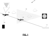
- FIG. 1 is a diagram depicting an example operating environment 100 in which visualization assistance queues may be provided for flight crew use.
- visualization assistance queues may be provided for flight crew use.
- the apparatus, systems, techniques and articles described herein provide visualization assistance queues on multiple cockpit display screens that can help the flight crew maintain separation between a target aircraft and an ownship during an approach using visual separation rules.
- air traffic control (ATC) 102 provides clearance information to the flight crew on an ownship 104 indicating the identification designation for a target aircraft 106 to follow, for example, during a landing procedure.
- the flight crew of the ownship may report "Traffic in sight" to ATC 102, designate the target aircraft 106 in its aircraft equipment, and select an alerting distance threshold (e.g., a pre-selected distance) as a minimum separation distance between the ownship 104 and the target aircraft 106 the flight crew would like to maintain.
- the flight crew of the ownship 104 may adjust the ownship aircraft speed based on an out the window view of the target aircraft 106 to maintain a desired ownship separation from the target aircraft 106.
- the flight crew may adjust the aircraft speed of the ownship 104 based on information provided by a visualization assistance system 110 to maintain ownship separation.
- Use of the visualization assistance system 110 can improve flight crew situational awareness.
- Use of the visualization assistance system 110 may end when the target aircraft 106 lands, e.g., at a runway 114.
- FIG. 2 is a block diagram of an example visualization assistance system 200.
- the example visualization assistance system 200 is configured to provide visual cues 201 to flight crew on multiple displays - a navigation display (ND) 202, a primary flight display (PFD) 204, and/or a heads up display (HUD) 205 - while an ownship follows a lead (target) aircraft during an approach procedure that requires the use of visual separation rules. This can help make the flight crew more situational aware as the flight crew adjusts its view between the window to the outside, the ND 202, the PFD 204, and/or HUD 205.
- ND navigation display
- PFD primary flight display
- HUD heads up display
- the example visualization assistance system 200 is configured to provide visual cues to both the SVS 206 and the HSI 208, to additionally improve the situational awareness of flight crew by providing four different sources of visual cues.
- the example visualization assistance system 200 is configured to retrieve traffic data from a traffic computer 210 onboard the ownship from a traffic source such as ADS-B, ADS-R, TIS-B or other data from the preceding aircraft, aircraft data from avionics systems 212 such as the FMS (flight management system), and flight crew input 214.
- the example visualization assistance system 200 is implemented using a controller.
- the controller includes at least one processor and a computer-readable storage device or media encoded with programming instructions for configuring the controller.
- the processor may be any custom-made or commercially available processor, a central processing unit (CPU), a graphics processing unit (GPU), an application specific integrated circuit (ASIC), a field programmable gate array (FPGA), an auxiliary processor among several processors associated with the controller, a semiconductor-based microprocessor (in the form of a microchip or chip set), any combination thereof, or generally any device for executing instructions.
- the computer readable storage device or media may include volatile and non-volatile storage in read-only memory (ROM), random-access memory (RAM), and keep-alive memory (KAM), for example.
- KAM is a persistent or non-volatile memory that may be used to store various operating variables while the processor is powered down.
- the computer-readable storage device or media may be implemented using any of a number of known memory devices such as PROMs (programmable read-only memory), EPROMs (electrically PROM), EEPROMs (electrically erasable PROM), flash memory, or any other electric, magnetic, optical, or combination memory devices capable of storing data, some of which represent executable programming instructions, used by the controller.
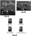
- FIGS. 3A, 3B, 3C , 3D, and 4 are diagrams depicting example visualization assistance queues that the example visualization system 200 may cause to be displayed on a ND 202 for flight crew use during an approach using visual separation rules.
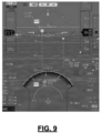
- FIGS. 5A, 5B , 6 , 7A, 7B , 8 and 9 are diagrams depicting example visualization assistance queues that the example visualization system 200 may cause to be displayed on a PFD 204 for flight crew use during an approach using visual separation rules.
- the example visualization assistance system 200 is configured to receive a selection of a target icon 302, that represents a target aircraft ahead of the ownship.
- the ND may display one or more potential target aircraft via icons.
- the selection of an icon 302 may cause the opening of a dialog box 304 from which the selected icon and the aircraft represented by the icon 302 may be designated as traffic to follow (TTF) using the example visualization assistance system 200.
- TTF traffic to follow
- the example system 200 Upon receiving a selection, the example system 200 is configured to make the selected target icon 302 become more visually pronounced, for example, by changing the color of the icon 302 (e.g. to green) and/or causing an area 306 surrounding the target icon to be displayed in a specific shape or color (e.g., green box).
- the example system 200 is configured to cause the display of a call sign (or flight ID) indicator 308 that provides the call sign/flight ID of the target aircraft, cause a display of a ground speed indicator 310 that provides the ground speed of the target aircraft, and relative numerical altitude 312 with a + sign for traffic above the ownship or - sign for traffic below the ownship. Traffic the same altitude is displayed with no preceding symbol.
- the fixed size vertical sense arrow 314 is displayed as an upward arrow for ascending traffic and a downward arrow for descending traffics.
- the example system 200 is configured to provide a range ring symbol 316 that indicates a relative distance in front of an ownship symbol on the ND and a numeric value 318 for a flight crew selected minimum range value wherein the minimum range value (threshold value) is equal to a minimum flight crew selected desired separation distance between the target aircraft and the ownship.
- the example system 200 is configured to cause the distance between the selected target icon 302, the range ring symbol 316 and an ownship symbol 320 on the ND to be proportional to the horizontal distance between the actual target aircraft, the threshold distance and the actual ownship.
- the visualization assistance system 200 is further configured to systematically adjust the position of the selected target icon 302 relative to the first range ring symbol 316 and the ownship symbol 320 on the ND.
- the example system 200 is further configured to provide a differential ground speed widget 322 that provides an alpha numeric indication of the differential ground speed (DGS) between the target aircraft and the ownship, and a differential ground speed symbol 324 that provides a graphical indication of whether the ownship is slower or faster than preceding aircraft 306.
- the differential ground speed symbol 324 is configured to provide a differential speed indicator symbol that indicates a range of differential speeds between the target and the ownship.
- a back chevron 326 below an ownship symbol 320 indicates a negative differential ground speed (e.g., the ownship speed is slower than preceding aircraft), a single chevron 328 above the ownship symbol 320 indicates a positive differential speed of 1 to 24 knots ( e.g., the ownship is slightly faster that preceding aircraft), a directional triangle 330 above the ownship symbol 320 indicates a positive differential speed of 25 to 49 knots, and a directional triangle with a chevron 332 above the ownship symbol 320 indicates a positive differential speed of 50 or more knots.
- the example visualization assistance system 200 may also be configured to cause the display of the horizontal range between the target aircraft and the ownship in a location 334 on the ND adjacent to the differential ground speed magnitude.
- the example visualization assistance system 200 is configured to cause a caution alert to be presented, for example, by changing the color of the target symbol 336 and call sign/flight ID 338 ( e.g., to an amber color), to cause the display of a label 340 ( e.g., an UNABLE label) adjacent to the traffic icon 336, and to cause the area surrounding the target icon (e.g ., area 306) to no longer be displayed in the specific shape or color in which it was displayed before the presentation of the caution alert.
- a label 340 e.g., an UNABLE label
- the example visualization assistance system 200 is configured to provide icon, widgets and symbols on the PFD 204 that are similar to those provided by the visualization assistance system 200 on the ND 202.
- the example visualization assistance system 200 is configured to position, on an SVS (a three dimensional (3D) synthetic vision system) display section of a primary flight display (PFD), one or more traffic icons 502, 503 each representative of an aircraft ahead of the ownship, wherein the size of each traffic icon 502, 503 is scaled based on proximity to the ownship, and wherein a traffic icon 503 for a first traffic aircraft is smaller than a traffic icon 502 for a second traffic aircraft when the first traffic aircraft is further away from the ownship than the second traffic aircraft.
- SVS three dimensional (3D) synthetic vision system
- the example visualization assistance system 200 is also configured to position, on an HSI (horizontal situation indicator) section of the PFD, a TTF icon 602 representative of the lead aircraft when a TTF has been designated. Similar to the traffic icon 302 on the ND, the TTF icon 602 may include a designation of the call sign/flight ID 608 for the TTF, the ground speed 610 of the TTF, and a numerical representation of an altitude difference 612 between the TTF and the ownship.
- HSI horizontal situation indicator
- the example visualization assistance system 200 is configured to cause a range ring symbol 616 that indicates a relative distance in front of an ownship and a numeric representation 618 of the flight crew selected threshold distance (similar to range ring symbol 316) to be displayed on the HSI section of the PFD.
- the distance between the TTF icon 602, the range ring symbol 616 and an ownship symbol 620 on the HSI is proportional to the horizontal distance between the actual TTF, the threshold distance and the actual ownship. Selection of either the traffic icon 302 on the ND, the traffic icon 502 on the SVS, or the TTF icon 602 allows for entry of the threshold distance from the ND, the SVS or the HSI.
- the example visualization assistance system 200 is further configured to systematically adjust ( e.g. , periodically) the position of the TTF icon 602 relative to the range ring symbol 616 and the ownship symbol 620 on the HSI.
- the example visualization assistance system 200 is configured to cause to be displayed, on the PFD, a numerical representation 622 of the differential ground speed between the TTF and the ownship and a differential ground speed symbol 624 representative of a range of differential ground speeds.
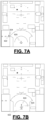
- the example visualization assistance system 200 is configured to cause to be displayed, adjacent to the ownship symbol 620 on the HSI, the numerical representation 622 of the differential ground speed difference between the TTF and the ownship, and the differential ground speed symbol 624 representative of a range of differential ground speeds as illustrated in FIGS. 6 and 7B .
- the visualization assistance system 200 is configured to cause the numerical representation 622 of the differential ground speed and the differential ground speed symbol 624 to be displayed adjacent to an existing groundspeed display on the PFD as illustrated in FIG. 7A .
- the example visualization assistance system 200 is configured to estimate an airspeed target 802 at which to fly to maintain a desired distance between the ownship and the TTF and cause the estimated airspeed target 802 to be displayed on the SVS.
- the estimated airspeed target 802 may be displayed ( e.g. , green line and diamond) in an airspeed indicator section 804 on the SVS or HUD.
- the example visualization assistance system 200 is configured to estimate the airspeed target 802 using a current ownship airspeed, wind speed and direction, current ownship groundspeed, and differential groundspeed between the TTF and the ownship. This information may be determined from information from the traffic computer 210, sensors, and avionics systems 212 on the ownship.
- the example visualization assistance system 200 is further configured to cause a vertical line 806 from the TTF icon 502 displayed on the SVS to provide an indication of the distance between the TTF and the ownship. Also, the visualization assistance system 200 could be configured to provide some or all of the features depicting in FIG. 8 based on the target platform or the personal preference of the flight crew.
- the example visualization assistance system 200 is configured to cause the state of the TTF icon 502 displayed on the SVS and the TTF icon 602 displayed on HSI to change (e.g ., different color and/or shape) when the TTF transitions to a TCAS Traffic Advisory (TA) state due to inadequate separation.
- the example visualization assistance system 200 is configured to cause an alert to be displayed on both the ND and the PFD when traffic that becomes a potential hazard is detected.
- the TFF 602 may also no longer meets minimum specified criteria, such as the threshold distance is violated or the ADS-B has dropped out.
- the example visualization assistance system 200 is configured to cause similar types of range advisory alerts to be displayed on both the ND and the PFD.
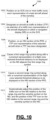
- FIG. 10 is a process flow chart depicting an example process 1000 in a trail aircraft for providing visual and aural cues to flight crew on multiple displays (e.g. , ND, PFD, and HUD) while following a proceeding aircraft during an approach using visual separation rules.
- the order of operation within the process 1000 is not limited to the sequential execution as illustrated in the figure, but may be performed in one or more varying orders as applicable and in accordance with the present disclosure.
- the example process 1000 includes positioning on an SVS (and/or HUD) one or more traffic icons, each representative of a lead aircraft ahead of the ownship (operation 1002).
- the size of each traffic icon is scaled based on proximity to ownship. For example, a traffic icon may be smaller when the lead aircraft is further away from the ownship.
- the example process 1000 includes designating an aircraft as traffic to follow (TTF) via selection of a traffic icon representative of the aircraft displayed on either a navigation display (ND) or on the SVS/HUD (operation 1004). Selection of either a traffic icon on the ND or SVS/HUD results in designation of the lead aircraft represented by the traffic icon as TTF and results in both traffic icons on the ND and SVS/HUD being made to more visually stand out (e.g., pixels surrounding the icon to be displayed in a different color or intensity or shading of the pixels representing the icon to be displayed in a different color or intensity);
- the example process 1000 includes positioning, on an HSI (horizontal situation indicator) section of the PFD, a TTF icon representative of the selected aircraft when a TTF has been designated (operation 1006).
- the TTF icon on the HSI may include a designation of the call sign/flight ID for the TTF, the ground speed of the TTF, and a numerical representation of an altitude difference between the TTF and the ownship.
- the example process 1000 includes causing a first range ring symbol along with a numerical representation of a flight crew selected threshold distance to be displayed on the ND adjacent the first range ring symbol (operation 1008).
- the threshold distance is flight crew selected as a minimum separation distance between the TTF and the ownship.
- the distance between the traffic icon, the first range ring and an ownship symbol on the ND is proportional to the horizontal distance between the actual TTF, the threshold distance and the actual ownship
- the example process 1000 includes causing a second range ring symbol along with a numerical representation of the flight crew selected threshold distance to be displayed on the HSI section of the PFD (operation 1010).
- the distance between the traffic icon, the second range ring and an ownship symbol on the HSI is proportional to the horizontal distance between the actual TTF, the threshold distance and the actual ownship. Also, selection of either the traffic icon on the ND, the traffic icon on the SVS, or the TTF icon on the HSI allows for entry of the threshold distance from the ND, the SVS or the HSI.
- the example process 1000 further includes systematically adjusting the position of the traffic icon on the ND relative to the first range ring and the ownship symbol on the ND, and the position of the TTF icon on the HSI relative to the second range ring and the ownship symbol on the HSI (operation 1012).
- Described herein are apparatus, systems, techniques and articles for increasing the situational awareness of the flight crew by providing a simultaneous two-dimensional (2D) and three-dimensional (3D) presentation of visual cues on multiple displays to enhance awareness of traffic to follow, separation criteria and/or differential ground speed.
- the visualization assistance may be configured to cause the numerical representation of the differential ground speed and the differential ground speed symbol to be displayed either adjacent to an ownship symbol on the SVS or adjacent to an existing groundspeed display on the SVS.
- the visualization assistance system may be further configured to: estimate an airspeed target at which to fly to maintain a desired distance between the ownship and the TTF; and cause the estimated airspeed target to be displayed on the SVS.
- the visualization assistance system may be configured to cause the estimated airspeed target to be displayed in an airspeed indicator section on the SVS.
- the visualization assistance system may be configured to estimate the airspeed target using a current ownship airspeed, wind speed and direction, current ownship groundspeed, and differential groundspeed between the TTF and the ownship.
- the visualization assistance system may be further configured to cause the state of the TFF symbol on SVS and the TTF symbol on the HSI to change when the TTF no longer meets minimum CAVS criteria.
- the third TTF icon may include a designation of the call sign/flight ID for the TTF, the ground speed of the TTF, and a numerical representation of an altitude difference between the TTF and the ownship.
- method may further comprise: causing to be displayed, adjacent to an ownship symbol on the ND, a numerical representation of the differential ground speed between the TTF and ownship and a differential ground speed symbol representative of a range of differential ground speeds; and causing to be displayed, on the SVS, a numerical representation of the differential ground speed between the TTF and the ownship and a differential ground speed symbol representative of a range of differential ground speeds.
- the method may comprise causing the numerical representation of the differential ground speed and the differential ground speed symbol to be displayed either adjacent to an ownship symbol on the SVS or adjacent to an existing groundspeed display on the SVS/HUD.
- the method may further comprise: estimating an airspeed target at which to fly to maintain a desired distance between the ownship and the TTF; and causing the estimated airspeed target to be displayed on the SVS/HUD.
- the method may comprise causing the estimated airspeed target to be displayed in an airspeed indicator section on the SVS/HUD.
- the method may comprise estimating the airspeed target using a current ownship airspeed, wind speed and direction, current ownship groundspeed, and differential groundspeed between the TTF and the ownship.
- the method may further comprise causing a vertical line from TTF symbol displayed on SVS to TTF symbol displayed on PFD to provide indication of how close the TTF is from ownship.
- the method may further comprise causing the state of the TFF symbol on SVS and the TTF symbol on the HSI to change when the TTF no longer meets minimum CAVS criteria.
- a non-transient computer readable media encoded with programming instructions that when executed by one or more processors in a trail aircraft causes the one or more processors to perform a method of providing visual cues to flight crew on multiple displays while the trail aircraft follows a proceeding aircraft during an approach using visual separation rules is provided.
- the method comprises: positioning, on an SVS (synthetic vision system) display section of a primary flight display (PFD) or HUD, one or more traffic icons wherein each is representative of a lead aircraft ahead of an ownship and wherein the size of each traffic icon is scaled based on proximity to the ownship; designating a lead aircraft as traffic to follow (TTF) via selection of a first traffic icon representative of one lead aircraft displayed on a navigation display (ND) or via selection of a second traffic icon representative of the same lead aircraft displayed on the SVS, wherein selection of either the first traffic icon or the second traffic icon results in designation of the selected lead aircraft as TTF and results in both the first traffic icon and the second traffic icon being made to more visually stand out; and positioning, on an HSI (horizontal situation indicator) section of the PFD, a third TTF icon representative of the lead aircraft when a TTF has been designated.
- SVS synthetic vision system
- a visualization assistance system for providing visual cues to flight crew on multiple displays (e.g. , ND and PFD) while following a proceeding aircraft during an approach using visual separation rules.
- the visualization assistance system comprises one or more processors configured by programming instructions on non-transient computer readable media.
- the visualization assistance system is configured, with respect to the ND, to: receive the selection of an icon displayed on a navigation display (ND) that represents an aircraft ahead of the ownship aircraft, designate the selected aircraft as traffic to follow (TTF), and cause the selected icon to be highlighted; cause a range ring symbol along with a designation of a flight crew selected threshold distance to be displayed on the ND, the threshold distance equal to minimum flight crew selected separation distance between the TTF and ownship; and cause the display of a numerical representation of the differential ground speed between the TTF and ownship and a differential ground speed symbol representative of a range of differential ground speeds to be displayed adjacent to an ownship symbol on the ND;
- ND navigation display
- TTF traffic to follow
- the visualization assistance system is configured, with respect to the PFD, to: position, on HSI, widget representative of TTF and range ring symbol, the TTF widget including icon representative of TTF, call sign/flight ID for TTF, ground speed of TTF, numerical representation of altitude difference between TTF and ownship, numerical representation of the differential ground speed between the TTF and ownship and a differential ground speed symbol representative of a range of differential ground speeds to be displayed adjacent to an ownship symbol on the HSI; position, on the SVS, a selectable traffic symbol representative of traffic ahead of the ownship wherein the size of the traffic symbol is scaled based on proximity to ownship; highlight a traffic symbol on SVS that is representative of an aircraft that has been designated as a TTF; designate an aircraft as a TTF responsive to selection of a traffic symbol on SVS representative of the aircraft, wherein TTF is selectable from ND, SVS and HSI and threshold distance can be entered from ND, SVS or HSI; cause the display of a numerical representation of the differential ground
- Skilled artisans may implement the described functionality in varying ways for each particular application, but such implementation decisions should not be interpreted as causing a departure from the scope of the present invention, as defined in the appended claims.
- an embodiment of a system or a component may employ various integrated circuit components, e.g., memory elements, digital signal processing elements, logic elements, look-up tables, or the like, which may carry out a variety of functions under the control of one or more microprocessors or other control devices.
- integrated circuit components e.g., memory elements, digital signal processing elements, logic elements, look-up tables, or the like, which may carry out a variety of functions under the control of one or more microprocessors or other control devices.
- DSP digital signal processor
- ASIC application specific integrated circuit
- FPGA field programmable gate array
- a general-purpose processor may be a microprocessor, but in the alternative, the processor may be any conventional processor, controller, microcontroller, or state machine.
- a processor may also be implemented as a combination of computing devices, e.g., a combination of a DSP and a microprocessor, a plurality of microprocessors, one or more microprocessors in conjunction with a DSP core, or any other such configuration.
- a software module may reside in RAM memory, flash memory, ROM memory, EPROM memory, EEPROM memory, registers, hard disk, a removable disk, a CD-ROM, or any other form of storage medium known in the art.
- An exemplary storage medium is coupled to the processor such that the processor can read information from, and write information to, the storage medium.
- the storage medium may be integral to the processor.
- the processor and the storage medium may reside in an ASIC.
- the ASIC may reside in a user terminal.
- the processor and the storage medium may reside as discrete components in a user terminal.
Landscapes
- Engineering & Computer Science (AREA)
- Physics & Mathematics (AREA)
- General Physics & Mathematics (AREA)
- Aviation & Aerospace Engineering (AREA)
- Theoretical Computer Science (AREA)
- Computer Hardware Design (AREA)
- Radar, Positioning & Navigation (AREA)
- Remote Sensing (AREA)
- Human Computer Interaction (AREA)
- General Engineering & Computer Science (AREA)
- Traffic Control Systems (AREA)
Claims (10)
- Visualisierungsassistenzsystem (110) zum Bereitstellen von visuellen Hinweisen für eine Flugbesatzung auf mehreren Anzeigen, die betriebsfähig mit dem Visualisierungsassistenzsystem (110) verbunden werden können, während des Folgens eines sich fortbewegenden Flugzeugs bei einer Annäherung unter Verwendung von visuellen Trennungsregeln, wobei das Visualisierungsassistenzsystem einen oder mehrere Prozessoren umfasst, die durch Programmieren von Anweisungen auf einem nicht flüchtigen computerlesbaren Medium konfiguriert sind, wobei das Visualisierungsassistenzsystem dazu konfiguriert ist,ein oder mehrere Verkehrsicons auf einem Ausschnitt einer synthetischen Sichtsystem-, SVS-, Anzeige (206) einer primären Fluganzeige, PFD, (204) oder einer Head-up-Anzeige, HUD, zu positionieren, wobei jedes ein führendes Flugzeug darstellt, das einem Trägerflugzeug voraus ist, und wobei die Größe jedes Verkehrsicons auf Basis einer Nähe zu dem Trägerflugzeug skaliert ist;ein oder mehrere Verkehrsicons auf einer Navigationsanzeige, ND, bereitzustellen;ein führendes Flugzeug als zu folgenden Verkehr, TTF, zu kennzeichnen, mittels einer Auswahl eines ersten Verkehrsicons (302) durch die Flugzeugbesatzung, das ein auf der ND angezeigtes führendes Flugzeug darstellt, oder mittels einer Auswahl eines zweiten Flugzeugicons durch die Flugzeugbesatzung, welches dasselbe führende Flugzeug darstellt, das auf der SVS (602) angezeigt wird, wobei eine Auswahl entweder des ersten Verkehrsicons oder des zweiten Verkehrsicons in einer Kennzeichnung des ausgewählten führenden Flugzeugs als TTF resultiert und auch darin resultiert, dass sowohl das erste Verkehrsicon als auch das zweite Verkehrsicon visuell stärker hervorgehoben werden; undauf einem horizontalen Situationsindikator-, HSI-, Ausschnitt der PFD ein drittes TTF-Icon zu positionieren, welches das führende Flugzeug darstellt, wenn ein TTF gekennzeichnet wurde.
- Visualisierungsassistenzsystem nach Anspruch 1, wobei das dritte TTF-Icon eine Kennzeichnung des Rufzeichens oder der Flug-ID (608) für das TTF, die Bodengeschwindigkeit (610) des TTF und eine numerische Darstellung einer Höhendifferenz (612) zwischen dem TTF und dem Trägerflugzeug beinhaltet.
- Visualisierungsassistenzsystem nach Anspruch 1, das ferner dazu konfiguriert ist,zu veranlassen, dass ein erstes Bereichsringsymbol (316) zusammen mit einer numerischen Darstellung (312) einer von einer Flugzeugbesatzung ausgewählten Schwellenwertentfernung auf der ND angrenzend zu dem ersten Bereichsringsymbol angezeigt wird, wobei die Schwellenwertentfernung gleich einer von einer Flugzeugbesatzung ausgewählten Mindesttrennungsentfernung zwischen dem TTF und dem Trägerflugzeug ist, und wobei die Entfernung zwischen dem ersten Verkehrsicon, dem ersten Bereichsringsymbol und einem Trägerflugzeug-Symbol auf der ND proportional zu der horizontalen Entfernung zwischen dem tatsächlichen TTF, der Schwellenwertentfernung und dem tatsächlichen Trägerflugzeug ist; undzu veranlassen, dass ein zweites Bereichsringsymbol (616) zusammen mit einer numerischen Darstellung (618) der von der Flugzeugbesatzung ausgewählten Schwellenwertentfernung auf dem HSI-Ausschnitt der PFD angezeigt wird, wobei die Entfernung zwischen dem dritten Verkehrsicon, dem zweiten Bereichsringsymbol und einem Trägerflugzeug-Symbol (620) auf dem HSI proportional zu der horizontalen Entfernung zwischen dem tatsächlichen TTF, der Schwellenwertentfernung und dem tatsächlichen Trägerflugzeug ist, und wobei eine Auswahl von entweder dem ersten Verkehrsicon, dem zweiten Verkehrsicon oder dem dritten Verkehrsicon eine Eingabe der Schwellenwertentfernung von der ND, dem SVS oder dem HSI ermöglicht.
- Visualisierungsassistenzsystem nach Anspruch 3, das ferner dazu konfiguriert ist, systematisch die Position des ersten Verkehrsicons relativ zu dem ersten Bereichsringsymbol und dem Trägerflugzeug-Symbol auf der ND sowie die Position des dritten Verkehrsicons relativ zu dem zweiten Bereichsringsymbol und dem Trägerflugzeug-Symbol auf dem HSI anzupassen.
- Visualisierungsassistenzsystem nach Anspruch 1, das ferner dazu konfiguriert ist,zu veranlassen, dass eine numerische Darstellung (322) der Differenzbodengeschwindigkeit zwischen dem TTF und einem Trägerflugzeug und ein Differenzbodengeschwindigkeitssymbol (324), das einen Bereich von Differenzbodengeschwindigkeiten darstellt, angrenzend zu einem Trägerflugzeug-Symbol auf der ND angezeigt wird; undzu veranlassen, dass eine numerische Darstellung (622) der Differenzbodengeschwindigkeit zwischen dem TTF und dem Trägerflugzeug und ein Differenzbodengeschwindigkeitssymbol (624), das einen Bereich von Differenzbodengeschwindigkeiten darstellt, auf der PFD angezeigt wird.
- Visualisierungsassistenzsystem nach Anspruch 1, das ferner dazu konfiguriert ist,ein Fluggeschwindigkeitsziel zu schätzen, mit dem geflogen werden muss, um eine gewünschte Entfernung zwischen dem Trägerflugzeug und dem TTF aufrechtzuerhalten; undzu veranlassen, dass das geschätzte Fluggeschwindigkeitsziel (802) auf dem SVS oder der HUD angezeigt wird.
- Visualisierungsassistenzsystem nach Anspruch 1, das ferner dazu konfiguriert ist, eine vertikale Linie (806) von dem auf dem SVS angezeigten TTF-Symbol zu dem auf der PFD angezeigten TTF-Symbol zu veranlassen, um eine Angabe eines TTF-Bereichs bereitzustellen.
- Computerimplementiertes Verfahren in einem verfolgenden Flugzeug zum Bereitstellen visueller Hinweise für eine Flugzeugbesatzung auf mehreren Anzeigen während des Folgens eines sich fortbewegenden Flugzeugs bei einer Annäherung unter Verwendung von visuellen Trennungsregeln, das Verfahren umfassend:Positionieren eines oder mehrerer Verkehrsicons auf einem Ausschnitt einer synthetischen Sichtsystem-, SVS-, Anzeige (206) einer primären Fluganzeige (PFD) (204) oder einer Head-up-Anzeige, HUD, wobei jedes ein führendes Flugzeug darstellt, das einem Trägerflugzeug voraus ist, und wobei die Größe jedes Verkehrsicons auf Basis einer Nähe zu dem Trägerflugzeug skaliert ist;Bereitstellen eines oder mehrerer Verkehrsicons auf einer Navigationsanzeige, ND;Kennzeichnen eines führenden Flugzeugs als zu folgenden Verkehr, TTF, mittels einer Auswahl eines ersten Verkehrsicons (302) durch die Flugzeugbesatzung, das ein auf der ND angezeigtes führendes Flugzeug darstellt, oder mittels einer Auswahl eines zweiten Flugzeugicons (602) durch die Flugzeugbesatzung, welches dasselbe führende Flugzeug darstellt, das auf der SVS angezeigt wird, wobei eine Auswahl entweder des ersten Verkehrsicons oder des zweiten Verkehrsicons in einer Kennzeichnung des ausgewählten führenden Flugzeugs als TTF resultiert und auch darin resultiert, dass sowohl das erste Verkehrsicon als auch das zweite Verkehrsicon visuell stärker hervorgehoben werden; undPositionieren auf einem horizontalen Situationsindikator-, HSI-, Ausschnitt der PFD eines dritten TTF-Icons, welches das führende Flugzeug darstellt, wenn ein TTF gekennzeichnet wurde.
- Verfahren nach Anspruch 8, ferner umfassend:Veranlassen, dass ein erstes Bereichsringsymbol (316) zusammen mit einer numerischen Darstellung (318) einer von einer Flugzeugbesatzung ausgewählten Schwellenwertentfernung auf der ND angrenzend zu dem ersten Bereichsringsymbol angezeigt wird, wobei die Schwellenwertentfernung gleich einer von einer Flugzeugbesatzung ausgewählten Mindesttrennungsentfernung zwischen dem TTF und dem Trägerflugzeug ist, und wobei die Entfernung zwischen dem ersten Verkehrsicon, dem ersten Bereichsringsymbol und einem Trägerflugzeug-Symbol (320) auf der ND proportional zu der horizontalen Entfernung zwischen dem tatsächlichen TTF, der Schwellenwertentfernung und dem tatsächlichen Trägerflugzeug ist; undVeranlassen, dass ein zweites Bereichsringsymbol (616) zusammen mit einer numerischen Darstellung (618) der von der Flugzeugbesatzung ausgewählten Schwellenwertentfernung auf dem HSI-Ausschnitt der PFD angezeigt wird, wobei die Entfernung zwischen dem dritten Verkehrsicon, dem zweiten Bereichsringsymbol und einem Trägerflugzeug-Symbol (620) auf dem HSI proportional zu der horizontalen Entfernung zwischen dem tatsächlichen TTF, der Schwellenwertentfernung und dem tatsächlichen Trägerflugzeug ist, und wobei eine Auswahl von entweder dem ersten Verkehrsicon, dem zweiten Verkehrsicon oder dem dritten Verkehrsicon eine Eingabe der Schwellenwertentfernung von der ND, dem SVS oder dem HSI ermöglicht.
- Verfahren nach Anspruch 9, ferner umfassend das systematische Anpassen der Position des ersten Verkehrsicons relativ zu dem ersten Bereichsringsymbol und dem Trägerflugzeug-Symbol auf der ND sowie der Position des dritten Verkehrsicons relativ zu dem zweiten Bereichsringsymbol und dem Trägerflugzeug-Symbol auf dem HSI.
Applications Claiming Priority (1)
| Application Number | Priority Date | Filing Date | Title |
|---|---|---|---|
| US16/456,924 US10713960B1 (en) | 2019-06-28 | 2019-06-28 | Presentation of 2D and 3D assisted visual separation information |
Publications (2)
| Publication Number | Publication Date |
|---|---|
| EP3757973A1 EP3757973A1 (de) | 2020-12-30 |
| EP3757973B1 true EP3757973B1 (de) | 2024-10-16 |
Family
ID=71130852
Family Applications (1)
| Application Number | Title | Priority Date | Filing Date |
|---|---|---|---|
| EP20181516.4A Active EP3757973B1 (de) | 2019-06-28 | 2020-06-22 | Darstellung von 2d- und 3d-unterstützten visuellen trennungsinformationen |
Country Status (2)
| Country | Link |
|---|---|
| US (1) | US10713960B1 (de) |
| EP (1) | EP3757973B1 (de) |
Families Citing this family (14)
| Publication number | Priority date | Publication date | Assignee | Title |
|---|---|---|---|---|
| US11887495B2 (en) | 2018-04-27 | 2024-01-30 | Red Six Aerospace Inc. | Augmented reality for vehicle operations |
| US11869388B2 (en) | 2018-04-27 | 2024-01-09 | Red Six Aerospace Inc. | Augmented reality for vehicle operations |
| US11508255B2 (en) | 2018-04-27 | 2022-11-22 | Red Six Aerospace Inc. | Methods, systems, apparatuses and devices for facilitating provisioning of a virtual experience |
| US11002960B2 (en) | 2019-02-21 | 2021-05-11 | Red Six Aerospace Inc. | Methods, systems, apparatuses, and devices for facilitating provisioning of a virtual experience |
| US11436932B2 (en) | 2018-04-27 | 2022-09-06 | Red Six Aerospace Inc. | Methods and systems to allow real pilots in real aircraft using augmented and virtual reality to meet in a virtual piece of airspace |
| US12260766B2 (en) | 2020-12-09 | 2025-03-25 | Rockwell Collins, Inc. | Method for interactive heads-up display and control of traffic targets |
| US11366327B1 (en) | 2020-12-09 | 2022-06-21 | Rockwell Collins, Inc. | Heads-up user interface and controls for interactive heads-up display of traffic targets |
| US11562716B2 (en) | 2020-12-09 | 2023-01-24 | Rockwell Collins, Inc. | Heads-up user interface and voice activated controls for display of traffic targets |
| USD1019671S1 (en) * | 2021-03-29 | 2024-03-26 | Gulfstream Aerospace Corporation | Avionics display screen with graphical user interface for shark tooth auto-throttle anticipation cues |
| US11787557B2 (en) * | 2021-04-30 | 2023-10-17 | Honeywell International Inc. | Methods and systems for representing a time scale on a cockpit display |
| US12456265B2 (en) * | 2022-01-28 | 2025-10-28 | The United States Of America As Represented By The Secretary Of The Army | System and method for calculation and display of formation flight information on augmented reality display device |
| USD1052599S1 (en) * | 2022-10-20 | 2024-11-26 | Archer Aviation, Inc. | Display screen with animated avionics graphical user interface |
| US12462690B2 (en) | 2023-02-17 | 2025-11-04 | Honeywell International, Inc. | System and method to display differential ground speed on a cockpit display |
| EP4418239A1 (de) * | 2023-02-17 | 2024-08-21 | Honeywell International Inc. | System und verfahren zur anzeige der differentiellen bodengeschwindigkeit auf einer cockpitanzeige |
Citations (1)
| Publication number | Priority date | Publication date | Assignee | Title |
|---|---|---|---|---|
| EP2869285A1 (de) * | 2013-10-29 | 2015-05-06 | Honeywell International Inc. | System und Verfahren zur Aufrechterhaltung des Flugzeugabstands basierend auf Entfernung oder Zeit |
Family Cites Families (25)
| Publication number | Priority date | Publication date | Assignee | Title |
|---|---|---|---|---|
| US6963291B2 (en) | 2002-05-17 | 2005-11-08 | The Board Of Trustees Of The Leland Stanford Junior University | Dynamic wake prediction and visualization with uncertainty analysis |
| FR2854129B1 (fr) * | 2003-04-28 | 2007-06-01 | Airbus France | Dispositif d'affichage dans un cockpit d'aeronef d'informations concernant le trafic environnant |
| US7796055B2 (en) * | 2006-11-02 | 2010-09-14 | The Boeing Company | Runway status indication and traffic information display and filtering |
| US8825365B2 (en) * | 2007-05-23 | 2014-09-02 | Honeywell International Inc. | Methods and systems for detecting a potential conflict between aircraft on an airport surface |
| US7755516B2 (en) * | 2007-08-20 | 2010-07-13 | The Boeing Company | Traffic display system, aircraft including the display system and method of displaying off-scale traffic in the display system |
| US8188889B2 (en) * | 2007-12-14 | 2012-05-29 | The Boeing Company | Method and system for display of traffic information in the flight deck |
| US8099201B1 (en) | 2008-08-29 | 2012-01-17 | Rockwell Collins, Inc. | Vertical profile display with enhanced temporal depiction of navigation information |
| US8175761B2 (en) | 2009-02-17 | 2012-05-08 | Honeywell International Inc. | System and method for rendering a synthetic perspective display of a designated object or location |
| US8108133B2 (en) * | 2009-09-14 | 2012-01-31 | Honeywell International Inc. | Vehicle position keeping system |
| US8600651B2 (en) * | 2009-11-24 | 2013-12-03 | The Boeing Company | Filtering of relevant traffic for display, enhancement, and/or alerting |
| US10096254B2 (en) * | 2010-03-03 | 2018-10-09 | Elbit Systems Ltd. | System for guiding an aircraft to a reference point in low visibility conditions |
| US8566012B1 (en) | 2010-06-08 | 2013-10-22 | The Boeing Company | On-board aircraft system and method for achieving and maintaining spacing |
| US8604942B2 (en) * | 2011-11-08 | 2013-12-10 | Honeywell International Inc. | System and method for displaying a velocity rate-of-change indicator |
| US8736633B2 (en) * | 2011-11-09 | 2014-05-27 | Honeywell International Inc. | Traffic symbology on airport moving map |
| US20140249701A1 (en) | 2013-03-04 | 2014-09-04 | Honeywell International Inc. | System and method for managing an interval between aircraft |
| US9478140B2 (en) * | 2014-08-29 | 2016-10-25 | Honeywell International Inc. | System and method for displaying traffic and associated alerts on a three-dimensional airport moving map display |
| US9501936B2 (en) | 2014-09-02 | 2016-11-22 | Honeywell International Inc. | Aircraft systems and methods for displaying spacing information |
| US9536434B2 (en) * | 2014-12-12 | 2017-01-03 | The Boeing Company | Aircraft turns for interval management |
| US10852157B2 (en) | 2015-07-30 | 2020-12-01 | The Boeing Company | Guidance display for controlling aircraft turns for aircraft spacing |
| US10140878B2 (en) | 2015-09-10 | 2018-11-27 | Beeper Avionics Inc. | Method and system for pilot target aircraft and target obstacle alertness and awareness |
| US9646504B2 (en) | 2015-10-08 | 2017-05-09 | The Boeing Company | Flight deck displays to enable visual separation standard |
| US10311737B2 (en) | 2015-10-16 | 2019-06-04 | Aviation Communication & Surveillance Systems Llc | Systems and methods for selecting and designating ADS-B traffic |
| SG11201810080UA (en) | 2016-07-26 | 2019-02-27 | Milian International Solutions Ltd | System and method for 3d flight path display |
| US9997078B2 (en) * | 2016-09-09 | 2018-06-12 | Garmin International, Inc. | Obstacle determination and display system |
| US10490089B2 (en) | 2017-07-12 | 2019-11-26 | Honeywell International Inc. | Cockpit display of traffic information (CDTI) assisted visual separation employing a vertical situation display |
-
2019
- 2019-06-28 US US16/456,924 patent/US10713960B1/en active Active
-
2020
- 2020-06-22 EP EP20181516.4A patent/EP3757973B1/de active Active
Patent Citations (1)
| Publication number | Priority date | Publication date | Assignee | Title |
|---|---|---|---|---|
| EP2869285A1 (de) * | 2013-10-29 | 2015-05-06 | Honeywell International Inc. | System und Verfahren zur Aufrechterhaltung des Flugzeugabstands basierend auf Entfernung oder Zeit |
Also Published As
| Publication number | Publication date |
|---|---|
| EP3757973A1 (de) | 2020-12-30 |
| US10713960B1 (en) | 2020-07-14 |
Similar Documents
| Publication | Publication Date | Title |
|---|---|---|
| EP3757973B1 (de) | Darstellung von 2d- und 3d-unterstützten visuellen trennungsinformationen | |
| EP3321634B1 (de) | System und verfahren zur anzeige von landebahnüberschreitungsinformationen | |
| EP2028633B1 (de) | Verkehrsanzeigesystem, Flugzeug mit dem Anzeigesystem und Verfahren zur Anzeige von Verkehr außerhalb des Anzeigebereichs auf dem Anzeigesystem | |
| EP1497808B1 (de) | Verfahren und system zur anzeige von zeitlichem abstand mehrerer anflüge | |
| US8099201B1 (en) | Vertical profile display with enhanced temporal depiction of navigation information | |
| CA2679910C (en) | Aircraft-centered ground maneuvering monitoring and alerting system | |
| EP3509052B1 (de) | Empfehlungen für sichere geschwindigkeit für systeme zum paarweisen anflug (pa) zur flugdeckverwaltung (fim) | |
| EP3816969A1 (de) | System und verfahren zur berechnung einer kurve, um einer spur hinter einem vorausfliegenden flugzeug zu folgen, unter einhaltung eines vorgegebenen abstandsintervalls | |
| EP1847899A1 (de) | Vorrichtung zur Anzeige von Landungsleistungsdaten | |
| EP2657923A2 (de) | System und Verfahren zum Anzeigen eines zeitweise verschobenen Landebahnschwellenwerts und Flugzeuglandungszielpunkt | |
| CN103630145B (zh) | 用于可能尾流湍流的呈现的系统和方法 | |
| CN110525669B (zh) | 通过图形可视化增强辅助目视间隔 | |
| EP3428903A1 (de) | Cdti-unterstützte visuelle trennung unter verwendung einer vertikalen situationsdarstellung | |
| EP3144637A1 (de) | Verfahren und system zur verbesserung des situationsbewusstseins unvorhergesehener gierbewegung auf einem drehflüglersystem | |
| CN105651305B (zh) | 用于集成导航的外向显示的系统和方法 | |
| EP3628976B1 (de) | Systeme und verfahren für dynamische auslesungen für primäre fluganzeigen | |
| EP2940674A1 (de) | System und verfahren zur anzeige von kontextempfindlichen notizen | |
| US20150015698A1 (en) | Methods and systems for optical aircraft detection | |
| CN104217617A (zh) | 通过在垂直位置显示器上显示高度过滤器限制线以便增加态势感知的系统和方法 | |
| AU2003234154B2 (en) | Multiple approach time domain spacing aid display method and system |
Legal Events
| Date | Code | Title | Description |
|---|---|---|---|
| PUAI | Public reference made under article 153(3) epc to a published international application that has entered the european phase |
Free format text: ORIGINAL CODE: 0009012 |
|
| STAA | Information on the status of an ep patent application or granted ep patent |
Free format text: STATUS: THE APPLICATION HAS BEEN PUBLISHED |
|
| AK | Designated contracting states |
Kind code of ref document: A1 Designated state(s): AL AT BE BG CH CY CZ DE DK EE ES FI FR GB GR HR HU IE IS IT LI LT LU LV MC MK MT NL NO PL PT RO RS SE SI SK SM TR |
|
| AX | Request for extension of the european patent |
Extension state: BA ME |
|
| STAA | Information on the status of an ep patent application or granted ep patent |
Free format text: STATUS: REQUEST FOR EXAMINATION WAS MADE |
|
| 17P | Request for examination filed |
Effective date: 20210625 |
|
| RBV | Designated contracting states (corrected) |
Designated state(s): AL AT BE BG CH CY CZ DE DK EE ES FI FR GB GR HR HU IE IS IT LI LT LU LV MC MK MT NL NO PL PT RO RS SE SI SK SM TR |
|
| RAP3 | Party data changed (applicant data changed or rights of an application transferred) |
Owner name: HONEYWELL INTERNATIONAL INC. |
|
| RIN1 | Information on inventor provided before grant (corrected) |
Inventor name: ZIARNICK, MELISSA Inventor name: BOUDA, TOMAS Inventor name: KHATWA, RATAN Inventor name: FEYEREISEN, THEA |
|
| RAP3 | Party data changed (applicant data changed or rights of an application transferred) |
Owner name: HONEYWELL INTERNATIONAL INC. |
|
| P01 | Opt-out of the competence of the unified patent court (upc) registered |
Effective date: 20230421 |
|
| GRAP | Despatch of communication of intention to grant a patent |
Free format text: ORIGINAL CODE: EPIDOSNIGR1 |
|
| STAA | Information on the status of an ep patent application or granted ep patent |
Free format text: STATUS: GRANT OF PATENT IS INTENDED |
|
| INTG | Intention to grant announced |
Effective date: 20240523 |
|
| GRAS | Grant fee paid |
Free format text: ORIGINAL CODE: EPIDOSNIGR3 |
|
| GRAA | (expected) grant |
Free format text: ORIGINAL CODE: 0009210 |
|
| STAA | Information on the status of an ep patent application or granted ep patent |
Free format text: STATUS: THE PATENT HAS BEEN GRANTED |
|
| AK | Designated contracting states |
Kind code of ref document: B1 Designated state(s): AL AT BE BG CH CY CZ DE DK EE ES FI FR GB GR HR HU IE IS IT LI LT LU LV MC MK MT NL NO PL PT RO RS SE SI SK SM TR |
|
| REG | Reference to a national code |
Ref country code: GB Ref legal event code: FG4D |
|
| REG | Reference to a national code |
Ref country code: CH Ref legal event code: EP |
|
| REG | Reference to a national code |
Ref country code: IE Ref legal event code: FG4D |
|
| REG | Reference to a national code |
Ref country code: DE Ref legal event code: R096 Ref document number: 602020039438 Country of ref document: DE |
|
| REG | Reference to a national code |
Ref country code: LT Ref legal event code: MG9D |
|
| REG | Reference to a national code |
Ref country code: NL Ref legal event code: MP Effective date: 20241016 |
|
| REG | Reference to a national code |
Ref country code: AT Ref legal event code: MK05 Ref document number: 1733584 Country of ref document: AT Kind code of ref document: T Effective date: 20241016 |
|
| PG25 | Lapsed in a contracting state [announced via postgrant information from national office to epo] |
Ref country code: NL Free format text: LAPSE BECAUSE OF FAILURE TO SUBMIT A TRANSLATION OF THE DESCRIPTION OR TO PAY THE FEE WITHIN THE PRESCRIBED TIME-LIMIT Effective date: 20241016 |
|
| PG25 | Lapsed in a contracting state [announced via postgrant information from national office to epo] |
Ref country code: NL Free format text: LAPSE BECAUSE OF FAILURE TO SUBMIT A TRANSLATION OF THE DESCRIPTION OR TO PAY THE FEE WITHIN THE PRESCRIBED TIME-LIMIT Effective date: 20241016 |
|
| PG25 | Lapsed in a contracting state [announced via postgrant information from national office to epo] |
Ref country code: IS Free format text: LAPSE BECAUSE OF FAILURE TO SUBMIT A TRANSLATION OF THE DESCRIPTION OR TO PAY THE FEE WITHIN THE PRESCRIBED TIME-LIMIT Effective date: 20250216 Ref country code: PT Free format text: LAPSE BECAUSE OF FAILURE TO SUBMIT A TRANSLATION OF THE DESCRIPTION OR TO PAY THE FEE WITHIN THE PRESCRIBED TIME-LIMIT Effective date: 20250217 Ref country code: HR Free format text: LAPSE BECAUSE OF FAILURE TO SUBMIT A TRANSLATION OF THE DESCRIPTION OR TO PAY THE FEE WITHIN THE PRESCRIBED TIME-LIMIT Effective date: 20241016 |
|
| PG25 | Lapsed in a contracting state [announced via postgrant information from national office to epo] |
Ref country code: FI Free format text: LAPSE BECAUSE OF FAILURE TO SUBMIT A TRANSLATION OF THE DESCRIPTION OR TO PAY THE FEE WITHIN THE PRESCRIBED TIME-LIMIT Effective date: 20241016 |
|
| PG25 | Lapsed in a contracting state [announced via postgrant information from national office to epo] |
Ref country code: BG Free format text: LAPSE BECAUSE OF FAILURE TO SUBMIT A TRANSLATION OF THE DESCRIPTION OR TO PAY THE FEE WITHIN THE PRESCRIBED TIME-LIMIT Effective date: 20241016 |
|
| PG25 | Lapsed in a contracting state [announced via postgrant information from national office to epo] |
Ref country code: ES Free format text: LAPSE BECAUSE OF FAILURE TO SUBMIT A TRANSLATION OF THE DESCRIPTION OR TO PAY THE FEE WITHIN THE PRESCRIBED TIME-LIMIT Effective date: 20241016 |
|
| PG25 | Lapsed in a contracting state [announced via postgrant information from national office to epo] |
Ref country code: NO Free format text: LAPSE BECAUSE OF FAILURE TO SUBMIT A TRANSLATION OF THE DESCRIPTION OR TO PAY THE FEE WITHIN THE PRESCRIBED TIME-LIMIT Effective date: 20250116 |
|
| PG25 | Lapsed in a contracting state [announced via postgrant information from national office to epo] |
Ref country code: LV Free format text: LAPSE BECAUSE OF FAILURE TO SUBMIT A TRANSLATION OF THE DESCRIPTION OR TO PAY THE FEE WITHIN THE PRESCRIBED TIME-LIMIT Effective date: 20241016 Ref country code: GR Free format text: LAPSE BECAUSE OF FAILURE TO SUBMIT A TRANSLATION OF THE DESCRIPTION OR TO PAY THE FEE WITHIN THE PRESCRIBED TIME-LIMIT Effective date: 20250117 Ref country code: AT Free format text: LAPSE BECAUSE OF FAILURE TO SUBMIT A TRANSLATION OF THE DESCRIPTION OR TO PAY THE FEE WITHIN THE PRESCRIBED TIME-LIMIT Effective date: 20241016 |
|
| PG25 | Lapsed in a contracting state [announced via postgrant information from national office to epo] |
Ref country code: PL Free format text: LAPSE BECAUSE OF FAILURE TO SUBMIT A TRANSLATION OF THE DESCRIPTION OR TO PAY THE FEE WITHIN THE PRESCRIBED TIME-LIMIT Effective date: 20241016 |
|
| PG25 | Lapsed in a contracting state [announced via postgrant information from national office to epo] |
Ref country code: RS Free format text: LAPSE BECAUSE OF FAILURE TO SUBMIT A TRANSLATION OF THE DESCRIPTION OR TO PAY THE FEE WITHIN THE PRESCRIBED TIME-LIMIT Effective date: 20250116 |
|
| PG25 | Lapsed in a contracting state [announced via postgrant information from national office to epo] |
Ref country code: SM Free format text: LAPSE BECAUSE OF FAILURE TO SUBMIT A TRANSLATION OF THE DESCRIPTION OR TO PAY THE FEE WITHIN THE PRESCRIBED TIME-LIMIT Effective date: 20241016 |
|
| PG25 | Lapsed in a contracting state [announced via postgrant information from national office to epo] |
Ref country code: DK Free format text: LAPSE BECAUSE OF FAILURE TO SUBMIT A TRANSLATION OF THE DESCRIPTION OR TO PAY THE FEE WITHIN THE PRESCRIBED TIME-LIMIT Effective date: 20241016 |
|
| PGFP | Annual fee paid to national office [announced via postgrant information from national office to epo] |
Ref country code: GB Payment date: 20250617 Year of fee payment: 6 |
|
| REG | Reference to a national code |
Ref country code: DE Ref legal event code: R097 Ref document number: 602020039438 Country of ref document: DE |
|
| PG25 | Lapsed in a contracting state [announced via postgrant information from national office to epo] |
Ref country code: EE Free format text: LAPSE BECAUSE OF FAILURE TO SUBMIT A TRANSLATION OF THE DESCRIPTION OR TO PAY THE FEE WITHIN THE PRESCRIBED TIME-LIMIT Effective date: 20241016 |
|
| PGFP | Annual fee paid to national office [announced via postgrant information from national office to epo] |
Ref country code: FR Payment date: 20250624 Year of fee payment: 6 |
|
| PG25 | Lapsed in a contracting state [announced via postgrant information from national office to epo] |
Ref country code: RO Free format text: LAPSE BECAUSE OF FAILURE TO SUBMIT A TRANSLATION OF THE DESCRIPTION OR TO PAY THE FEE WITHIN THE PRESCRIBED TIME-LIMIT Effective date: 20241016 |
|
| PG25 | Lapsed in a contracting state [announced via postgrant information from national office to epo] |
Ref country code: SK Free format text: LAPSE BECAUSE OF FAILURE TO SUBMIT A TRANSLATION OF THE DESCRIPTION OR TO PAY THE FEE WITHIN THE PRESCRIBED TIME-LIMIT Effective date: 20241016 |
|
| PG25 | Lapsed in a contracting state [announced via postgrant information from national office to epo] |
Ref country code: CZ Free format text: LAPSE BECAUSE OF FAILURE TO SUBMIT A TRANSLATION OF THE DESCRIPTION OR TO PAY THE FEE WITHIN THE PRESCRIBED TIME-LIMIT Effective date: 20241016 |
|
| PG25 | Lapsed in a contracting state [announced via postgrant information from national office to epo] |
Ref country code: IT Free format text: LAPSE BECAUSE OF FAILURE TO SUBMIT A TRANSLATION OF THE DESCRIPTION OR TO PAY THE FEE WITHIN THE PRESCRIBED TIME-LIMIT Effective date: 20241016 |
|
| PLBE | No opposition filed within time limit |
Free format text: ORIGINAL CODE: 0009261 |
|
| STAA | Information on the status of an ep patent application or granted ep patent |
Free format text: STATUS: NO OPPOSITION FILED WITHIN TIME LIMIT |
|
| PG25 | Lapsed in a contracting state [announced via postgrant information from national office to epo] |
Ref country code: SE Free format text: LAPSE BECAUSE OF FAILURE TO SUBMIT A TRANSLATION OF THE DESCRIPTION OR TO PAY THE FEE WITHIN THE PRESCRIBED TIME-LIMIT Effective date: 20241016 |
|
| 26N | No opposition filed |
Effective date: 20250717 |
|
| PGFP | Annual fee paid to national office [announced via postgrant information from national office to epo] |
Ref country code: CH Payment date: 20250701 Year of fee payment: 6 |
|
| REG | Reference to a national code |
Ref country code: DE Ref legal event code: R119 Ref document number: 602020039438 Country of ref document: DE |
|
| PG25 | Lapsed in a contracting state [announced via postgrant information from national office to epo] |
Ref country code: MC Free format text: LAPSE BECAUSE OF FAILURE TO SUBMIT A TRANSLATION OF THE DESCRIPTION OR TO PAY THE FEE WITHIN THE PRESCRIBED TIME-LIMIT Effective date: 20241016 |
|
| PG25 | Lapsed in a contracting state [announced via postgrant information from national office to epo] |
Ref country code: LU Free format text: LAPSE BECAUSE OF NON-PAYMENT OF DUE FEES Effective date: 20250622 |
|
| REG | Reference to a national code |
Ref country code: BE Ref legal event code: MM Effective date: 20250630 |
|
| PG25 | Lapsed in a contracting state [announced via postgrant information from national office to epo] |
Ref country code: IE Free format text: LAPSE BECAUSE OF NON-PAYMENT OF DUE FEES Effective date: 20250622 Ref country code: DE Free format text: LAPSE BECAUSE OF NON-PAYMENT OF DUE FEES Effective date: 20260101 |
|
| PG25 | Lapsed in a contracting state [announced via postgrant information from national office to epo] |
Ref country code: BE Free format text: LAPSE BECAUSE OF NON-PAYMENT OF DUE FEES Effective date: 20250630 |