EP3758149B1 - Conceptions de lentille de plaque à zone de fresnel pour des applications à micro-ondes - Google Patents
Conceptions de lentille de plaque à zone de fresnel pour des applications à micro-ondes Download PDFInfo
- Publication number
- EP3758149B1 EP3758149B1 EP20182092.5A EP20182092A EP3758149B1 EP 3758149 B1 EP3758149 B1 EP 3758149B1 EP 20182092 A EP20182092 A EP 20182092A EP 3758149 B1 EP3758149 B1 EP 3758149B1
- Authority
- EP
- European Patent Office
- Prior art keywords
- mask pattern
- lens plate
- antenna array
- waves
- fresnel zone
- Prior art date
- Legal status (The legal status is an assumption and is not a legal conclusion. Google has not performed a legal analysis and makes no representation as to the accuracy of the status listed.)
- Active
Links
Images


Classifications
-
- H—ELECTRICITY
- H01—ELECTRIC ELEMENTS
- H01Q—ANTENNAS, i.e. RADIO AERIALS
- H01Q19/00—Combinations of primary active antenna elements and units with secondary devices, e.g. with quasi-optical devices, for giving the antenna a desired directional characteristic
- H01Q19/06—Combinations of primary active antenna elements and units with secondary devices, e.g. with quasi-optical devices, for giving the antenna a desired directional characteristic using refracting or diffracting devices, e.g. lens
- H01Q19/062—Combinations of primary active antenna elements and units with secondary devices, e.g. with quasi-optical devices, for giving the antenna a desired directional characteristic using refracting or diffracting devices, e.g. lens for focusing
- H01Q19/065—Zone plate type antennas
-
- H—ELECTRICITY
- H01—ELECTRIC ELEMENTS
- H01Q—ANTENNAS, i.e. RADIO AERIALS
- H01Q21/00—Antenna arrays or systems
- H01Q21/0006—Particular feeding systems
- H01Q21/0031—Parallel-plate fed arrays; Lens-fed arrays
-
- H—ELECTRICITY
- H01—ELECTRIC ELEMENTS
- H01Q—ANTENNAS, i.e. RADIO AERIALS
- H01Q21/00—Antenna arrays or systems
- H01Q21/06—Arrays of individually energised antenna units similarly polarised and spaced apart
- H01Q21/061—Two dimensional planar arrays
- H01Q21/065—Patch antenna array
-
- H—ELECTRICITY
- H01—ELECTRIC ELEMENTS
- H01Q—ANTENNAS, i.e. RADIO AERIALS
- H01Q25/00—Antennas or antenna systems providing at least two radiating patterns
- H01Q25/007—Antennas or antenna systems providing at least two radiating patterns using two or more primary active elements in the focal region of a focusing device
- H01Q25/008—Antennas or antenna systems providing at least two radiating patterns using two or more primary active elements in the focal region of a focusing device lens fed multibeam arrays
Definitions
- the disclosure relates generally to an antenna unit and, in particular, to an antenna unit incorporating a variety of Fresnel zone plate lens designs utilizing patterned masks.
- Deployment of the 5G network has required the installation of many new antennas to send and receive 5G signals. Such antennas relay data throughout the network in a highly directional manner. Efficient sending and receiving of these 5G signals allows for the 5G network to be built out in an economical manner.
- JP 2002 171122 describes an antenna unit comprising a Fresnel zone plate.
- WO 2009/063384 describes an antenna unit comprising a Fresnel zone plate.
- an antenna unit may be based on a Fresnel zone plate.
- the first angle may be 0° and the mask pattern may be defined by an interference pattern produced when the Fresnel zone plate is irradiated by the second waves at the second angle.
- the mask pattern may comprise sections opaque to the first waves and to the second waves and sections transparent to the first waves and to the second waves.
- the mask pattern may comprise a difference in thickness between first sections and second sections that result in a path length difference equivalent to a wavelength of the first waves or second waves divided by two.
- the first waves and the second waves may each have a frequency in a range of 20 GHz to 100 GHz.
- a difference between the first angle and the second angle may be up to 45°.
- the Fresnel zone plate may comprise alternating rings opaque to the waves incident on the lens plate and rings transparent to the waves incident on the lens plate.
- the mask pattern may comprise a difference in thickness between first sections and second sections that result in a path length difference equivalent to a wavelength of the waves incident on the lens plate divided by two.
- the waves incident on the lens plate may have a frequency in a range of 20 GHz to 100 GHz.
- inventions of the disclosure relate to an antenna unit according to claim 6 or claim 7.
- the plurality of superimposed Fresnel zone plates may comprise at least three Fresnel zone plates that overlap along at least one of a horizontal axis or a vertical axis of the lens plate, the at least three Fresnel zone plates producing at least three focal points. Each of the at least three focal points may lie along a line.
- the plurality of superimposed Fresnel zone plates may comprise four Fresnel zone plates that overlap in such a way to produce four focal points that form a square.
- the mask pattern may comprise an obround Fresnel zone plate.
- the mask pattern may comprise two Fresnel zone plates in which a center ring of a first Fresnel zone plate overlaps with a center ring of a second Fresnel zone plate.
- Embodiments of the present disclosure relate to an antenna unit having a Fresnel zone plate lens with a mask pattern that manipulates the focal point(s) and/or direction of an incident incoming wave.
- the mask pattern allows for waves having two different incident angles to have the same focal spot on an antenna array of the antenna unit. Further, in embodiments, the mask pattern allows for the focal spot to be offset vertically and/or horizontally from the center position. In still further embodiments, the mask pattern is created by superimposing multiple Fresnel zone plates to produce multiple focal points that can be spaced out vertically and/or horizontally.
- the mask patterns disclosed herein include alternating opaque (absorbing or reflecting) and transparent sections or sections with alternating thicknesses whose spacings are dictated by the lens focal length at the specified microwave frequency.
- the mask patterns can be produced through various deposition or coating or printing techniques, such as screen printing, spray coating, slot coating, and thin film deposition techniques. Further, in embodiments, the mask patterns can be produced trough material removal or addition.
- 5G refers to signals transmitted via microwaves, in particular having a frequency of 20 GHz to 100 GHz.
- the 5G network includes many antenna units that transmit directional waves to other antenna units. Applicants have found a way to enhance the lens gain of the antenna units by focusing the waves incident upon the antenna units to specific, desired regions of an antenna array. In this way, the antenna units can transmit and receive over greater distances, thereby reducing the required number of antenna units in the network.
- Various embodiments of an antenna unit, in particular that is usable in the 5G infrastructure, are disclosed herein. These embodiments are presented by way of example and not by way of limitation.
- FIG. 1 depicts an embodiment of an antenna unit 10 having a housing 12 surrounding an antenna array 14.
- the antenna array 14 comprises a plurality of individual antennas, such as patch antennas, mounted to a ground plane.
- the patch antennas are rectangular sheets (i.e., "patches") of metal that may be connected with microstrip transmission lines so as to group the antennas into multiple phased arrays.
- the housing 12 includes a lens plate 16.
- the lens plate 16 is a planar surface arranged parallel to and spatially disposed from a plane defined by the antenna array 14.
- parallel or “substantially parallel” it is meant that the plane of the lens plate 16 is substantially geometrically parallel to within about +/- 15° to the plane of the antenna array, such as within about +/- 10°, such as within about +/- 5°, such as within about +/- 2° or for more complex geometry (e.g., slightly convex curve, etc.), the net angle is within about +/- 15°.
- the lens plate 16 focuses the intensity of electromagnetic waves incident upon the lens plate 16 onto a particular region of the antenna array 14.
- the lens plate 14 includes a mask pattern 18 including a series of first sections 20 and second sections 22.
- the mask pattern 18 focuses the incident waves via diffraction from the first sections 20 and the second sections 22.
- the first sections 20 are opaque, and the second sections 22 are transparent.
- oval it is meant that the first sections 20 block electromagnetic radiation of a particular wavelength from passing through the lens in the area of the first sections 20.
- transparent it is meant that the second sections 22 permit electromagnetic radiation of a particular wavelength to pass through the lens in the area of the second sections 22.
- the second sections 22 transmit at least 90% of electromagnetic radiation of a particular wavelength through the lens in the area of the second sections 22.
- the second sections 22 transmit at least 95% of electromagnetic radiation of a particular wavelength through the lens in the area of the second sections 22, and in still other embodiments, the second sections 22 transmit at least 98% of electromagnetic radiation of a particular wavelength through the lens in the area of the second sections 22.
- the first sections 20 have a different thickness than the second sections 22.
- a difference in thickness of the lens plate 16 is provided between the first sections 20 and the second sections 22.
- a difference in thickness between the first sections 20 and the second sections 22 is chose to result in a path length difference equivalent to the wavelength of the incident wave divided by two.
- the mask pattern 18 is based on the diffraction pattern produced by a wave of electromagnetic radiation incident on a Fresnel zone plate (FZP) as shown in FIG. 2 .
- FZP Fresnel zone plate
- the first sections 20 and the second sections 22 are a series of concentric rings that alternate between rings of the first section 20 and rings of the second section 22.
- r n is the radius of the nth ring of the FZP
- n is the integer number of rings
- ⁇ is the wavelength of the incident wave
- f is the focal length.
- the antenna array 14 would preferably be placed at the focal length f away from the lens plate 16 so that the maximum intensity of the wave is received by the antenna array 14.
- the incident angle ⁇ inc does not equal 0°
- the focal spot of the incident wave will not be directly in line with the axis perpendicular to the FZP. Instead, the focus of the obliquely incident wave will be off-center and diffuse as compared to the in-line and concentrated focal spot of an on-axis wave.
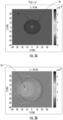
- FIG. 3A depicts an FZP for a wave with an incident angle ⁇ inc of 0°
- FIG. 3B illustrates the distribution of intensity for a diffracted wave having an incident angle ⁇ inc of 30° off the perpendicular in the x-direction.
- the focal spot of the diffracted wave is displaced more than 10 cm away from the center.
- the lens plate 16 would not diffract the incident wave to the desired region of the antenna array 14.
- the mask pattern 18 is based off the intensity distribution pattern shown in FIG. 3B . That is, the mask pattern 18 shown in FIG. 4A is substantially the same as the intensity distribution shown in FIG. 3B . As shown in FIG. 4B , when a wave is incident upon the mask pattern 18 at an incident angle of 30°, the intensity distribution has a focal spot 24 centered at 0 in the x- and y-directions with respect to the graph shown in FIG. 4B .
- the diffracted intensity distribution also has a focal spot 24 centered at 0 in the x- and y-directions as shown in FIG. 4C .
- the mask pattern 18 of FIG. 4A provides a centered and concentrated intensity for waves that are incident at both 0° ( FIG. 4C ) and 30° ( FIG. 4B ).
- the mask pattern 18 provides a centered and concentrated intensity for waves incident at angles of 0° ⁇ 5° and 30° ⁇ 5°. That is, the mask pattern 18 can concentrate the intensity of a range of incident waves centered on the desired directions of incidence. In embodiments, the degree of separation between the directions of incidence is up to 45°. Accordingly, antennas 10 utilizing such a mask pattern 18 on the lens plate 16 are able to receive signals from multiple directions, or antennas 10 that are restricted in the installation geometry can still direct an off-axis signal to a desired region of an antenna array 14.
- the mask pattern 18 can be used to deliberately move the focal spot 24 off-center.
- the embodiment discussed in relation to FIGS. 4A-4C were designed to provide an on-center focal spot in the case of an incident wave that was off-axis.
- the mask pattern 18 is configured to move the focal spot of an on-axis wave to an off-center position.
- the wave may be incident on the lens plate 16 along a first axis, and the mask pattern 18 will produce a focal spot that is not on that first axis but on another axis spatially disposed from the first axis.
- the mask pattern 18 is configured to move the focal spot, e.g., to irradiate a desired portion of an antenna array 14 (as shown in FIG. 1 ) that is not located along the axis of incidence, or to accommodate off-axis placement of the array 14.
- the mask pattern 18 is configured to move the focal spot at least 5 cm off-center.
- the mask pattern 18 is configured to move the focal spot at least 10 cm off-center, and in still another embodiment, the mask pattern 18 is configured to move the focal spot at least 20 cm off-center.
- the mask pattern is configured to move the focal spot up to 50 cm off center.
- FIG. 5A depicts a mask pattern 18 designed to move the focal spot 10 cm down in the y-direction.
- the mask pattern 18 is based on an FZP 26 in which the center ring of the FZP 26 is off-set from the geometric center of the lens plate 16.
- FIG. 5B depicts the intensity distribution for a diffracted, on-axis wave (i.e., on an axis running through the geometric center of the mask pattern 18).
- the focal point 24 is at the same position (i.e., located along the same axis) as the center ring of the FZP 26. That is, with respect to the antenna unit 10 of FIG.
- FIG. 5C depicts an offset of the FZP 26 by 20 cm, and as can be seen in FIG. 5D , the focal point 24 is also offset by 20 cm.
- the mask pattern 18 of FIGS. 5A and 5C may be useful, e.g., to accommodate deployment of the antenna unit 10 in situations where alignment of a phased antenna array with the lens plate 16 is not possible or is undesirable. Further, in embodiments, the antenna array 14 of the antenna 10 may not be centered within the housing 12. While the vertical position of the focal spot 24 was depicted as being moved in FIGS. 5A-5D , the horizontal position of the focal spot 24 could also be moved in embodiments by moving the center ring of the FZP 26 along the horizontal axis, and in other embodiments, the focal spot 24 can be moved both horizontally and vertically from the center of the mask pattern 18 by moving the center ring of the FZP 26 along both the horizontal and vertical axes.
- the mask pattern 18 is configured to provide multiple focal spots 24.
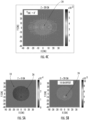
- FIG. 6A depicts an embodiment in which the mask pattern 18 comprises multiple superimposed FZP 26 across the x-direction. In general, each superimposed FZP 26 will produce its own focal spot 14.
- FIG. 6A includes three superimposed FZP 26: a central FZP 26a, a left FZP 26b, and a right FZP 26c. As shown in FIG. 6B , this pattern of FZP 26a, 26b, 26c produces three focal spots 24 in which each focal spot 24 is located at the center of each FZP 26a, 26b, 26c for an incident wave at an incident angle of 0°.
- each focal spot 24 is determined by the spacing of the FZP 26a, 26b, 26c.
- the focal spots 24 are quasi-uniform in that the intensity is slightly greater and more concentrated in the focal spot 24 behind the center FZP 26a than the intensity of the focal spots 24 behind the outer FZP 26b, 26c.
- a multi-focal spot mask pattern may be used, e.g., to focus the wave on both a primary and a backup antenna array 14 such that the antenna unit 10 easily be switched back and forth between the primary and backup antenna array if one is damaged.
- FIG. 7A depicts another embodiment in which the mask pattern 18 includes five superimposed FZP 26: a center FZP 26a, an intermediate left FZP 26b, a far left FZP 26c, an intermediate right FZP 26d, and a far right FZP 26e.
- the five, quasi-uniform focal spots 24 are produced behind the centers of each FZP 26a-26e.
- the embodiment of FIGS. 7A and 7B demonstrate that the intensity and concentration of the focal spots 24 decreases moving outward from the center focal spot 24, which is located behind the center FZP 26a.
- FIGS. 6A-6B and 7A-7B demonstrate that the focal spots 24 can be spaced along the horizontal axis of the antenna array 14.
- the focal spots 24 could instead be spaced along the vertical axis of the antenna array 14 by superimposing the FZP 26 across the vertical axis instead.
- the focal spots 24 of the embodiment depicted are all located along the same line as the other focal spots 24.
- the focal spots 24 can be arranged out of line from each other (see discussion of FIGS. 10A and 10B , below).
- FIG. 8A demonstrates another configuration of an FZP 26 that provides two horizontally separated focal spots.
- the FZP 26 in this instance is obround, comprising two semicircles separated by a rectangular section.
- the focal points 24 are located at the ends of the rectangular section between the semicircle portions.
- the obround FZP 26 can be arranged along the vertical axis instead of the horizontal axis to provide focal points spaced apart on the horizontal axis.
- the obround FZP 26 is arranged at an angle to both the horizontal and vertical axes to provide focal points 24 spaced apart diagonally.
- FIG. 9A depicts an embodiment in which a first offset FZP 26a is overlapped with a second offset FZP 26b.
- the FZP 26a, 26b are offset along the vertical axis such that the center ring of each FZP 26a, 26b is offset from the center of the lens plate 16.
- the center rings of the FZP 26a, 26b are also overlapped.
- the focal points 24 are located along the same axis as the center rings of the offset FZP 26a, 26b.
- FIG. 9C depicts another embodiment in which the center rings of FZP 26a, 26b are overlapped to a greater degree than in FIG. 9A .
- the focal points 24 are positioned closer together while still remaining offset.
- the overlapped and offset FZP 26a, 26b may be arranged along the horizontal axis instead of the vertical axis to provide focal points 24 spaced along the horizontal axis.
- FIG 10A depicts still another embodiment having multiple focal points 24 that are spaced apart.
- FIG. 10A includes four superimposed FZP 26a-26d.
- the FZP 26a-26d are arranged in a 2x2 array with overlapping quadrants.
- the focal points 24 are arranged in a square at the center of each FZP 26a-26d.
- the mask pattern 18 is fabricated using screen printing or sputter coating.
- modelled data for the mask pattern 18 can be converted to screen-printable file using pattern design software.
- the screen mesh, emulsion thickness, and tension based on the pattern resolution are determined for the screen printing process.
- the material of the lens plate e.g., glass having a thickness of 0.3-0.7 mm
- a microwave opaque material is selected for screen printing.
- the material can be absorbing or reflecting of microwaves. Examples include silver-based ink, silver nanowire-based ink.
- the screen area is flooded with the selected screen ink for the printing step, and when sufficient wetting of the screen surface is achieved, the print step is applied using varying print speed (mm/sec), gap (mm) and print pressure (KgF or psi).
- the thickness of the opaque material deposited onto the lens plate is about 10 to 15 ⁇ m thick.
- the ink is applied, it is baked or UV-cured.
- low E coating (such as those used for window applications) can be vacuum deposited on a pre-masked glass substrate and followed by the removal of the mask after deposition. Resistitivity values of 0.03-10 ⁇ /m indicate that the layer will be opaque to microwave in the frequency of interest.
Landscapes
- Aerials With Secondary Devices (AREA)
Claims (11)
- Unité d'antenne (10), comprenant :un réseau d'antennes (14) comprenant une pluralité d'antennes, le réseau d'antennes définissant un premier plan ; etune plaque de lentille (16) comprenant un motif de masque (18), la plaque de lentille définissant un second plan,ladite plaque de lentilles étant espacée du réseau d'antennes et ledit second plan de la plaque de lentilles étant sensiblement parallèle au premier plan du réseau d'antennes ;ledit motif de masque (18) étant configuré pour focaliser des premières ondes incidentes sur la plaque de lentille (16) par diffraction vers une première région du réseau d'antennes (14), les premières ondes étant incidentes sur la plaque de lentille selon un premier angle par rapport à un axe normal au second plan de la plaque de lentille ; etcaractérisée en ce quele motif de masque (18) est conçu pour focaliser des secondes ondes incidentes sur la plaque de lentille (16) par diffraction vers la première région du réseau d'antennes (14), les secondes ondes étant incidentes sur la plaque de lentille selon un second angle par rapport à l'axe, le second angle étant différent du premier angle ;
etledit motif de masque étant défini par un motif d'interférence produit par la superposition de deux motifs de masque. - Unité d'antenne (10) de la revendication 1, ledit motif de masque (18) étant basé sur une plaque à zone de Fresnel.
- Unité d'antenne (10) de la revendication 2, ledit motif de masque (18) étant défini par un motif d'interférence correspondant à des ondes avec deux angles incidents différents, ledit premier angle étant de 0°.
- Unité d'antenne (10) de l'une quelconque des revendications précédentes, ledit motif de masque (18) comprenant des sections (20) opaques aux premières ondes et aux secondes ondes et des sections (22) transparentes aux premières ondes et aux secondes ondes.
- Unité d'antenne (10) de l'une quelconque des revendications 1-3, ledit motif de masque (18) comprenant une différence d'épaisseur entre les premières sections (20) et les secondes sections (22) qui aboutissent à une différence de longueur de trajet équivalente à une longueur d'onde des premières ondes ou des secondes ondes divisées par deux.
- Unité d'antenne (10), comprenant :un réseau d'antennes (14) comprenant une pluralité d'antennes, le réseau d'antennes définissant un premier plan ; etune plaque de lentille (16) comprenant un motif de masque (18), la plaque de lentille définissant un second plan, ladite plaque de lentille étant espacée du réseau d'antennes et ledit second plan de la plaque de lentille étant sensiblement parallèle au premier plan du réseau d'antennes ;ledit motif de masque (18) étant configuré pour focaliser des ondes incidentes sur la plaque de lentille vers au moins deux foyers différents (24) à l'intérieur du réseau d'antennes, caractérisé en ce que le motif de masque comprend une plaque à zone de Fresnel oblongue.
- Unité d'antenne (10), comprenant :un réseau d'antennes (14) comprenant une pluralité d'antennes, le réseau d'antennes définissant un premier plan ; etune plaque de lentille (16) comprenant un motif de masque (18), la plaque de lentille définissant un second plan, ladite plaque de lentille étant espacée du réseau d'antennes et ledit second plan de la plaque de lentille étant sensiblement parallèle au premier plan du réseau d'antennes ;ledit motif de masque (18) étant configuré pour focaliser des ondes incidentes sur la plaque de lentille au niveau d'au moins deux foyers différents (24) à l'intérieur du réseau d'antennes, caractérisé en ce que le motif de masque comprend au moins deux plaques à zone de Fresnel superposées qui au moins partiellement se chevauchent et lesdits au moins deux foyers comprenant un foyer pour chacune des au moins deux plaques à zone de Fresnel superposées.
- Unité d'antenne (10) de la revendication 7, ladite pluralité de plaques à zone de Fresnel superposées (26) comprenant au moins trois plaques à zone de Fresnel qui se chevauchent le long d'au moins l'un d'un axe horizontal ou d'un axe vertical de la plaque de lentille, les au moins trois plaques à zone de Fresnel produisant au moins trois foyers (24).
- Unité d'antenne (10) de la revendication 8, ladite pluralité de plaques à zone de Fresnel superposées (26) comprenant quatre plaques à zone de Fresnel qui se chevauchent de telle façon à produire quatre foyers (24) qui forment un carré.
- Unité d'antenne (10) de la revendication 6, ledit motif de masque (18) comprenant deux plaques à zone de Fresnel (26) dans lesquelles un anneau central d'une première plaque à zone de Fresnel chevauche un anneau central d'une seconde plaque à zone de Fresnel.
- Unité d'antenne (10) selon l'une quelconque des revendications précédentes, ledit réseau d'antennes (14) comprenant au moins trois antennes.
Applications Claiming Priority (1)
| Application Number | Priority Date | Filing Date | Title |
|---|---|---|---|
| US201962867481P | 2019-06-27 | 2019-06-27 |
Publications (2)
| Publication Number | Publication Date |
|---|---|
| EP3758149A1 EP3758149A1 (fr) | 2020-12-30 |
| EP3758149B1 true EP3758149B1 (fr) | 2024-09-18 |
Family
ID=71143596
Family Applications (1)
| Application Number | Title | Priority Date | Filing Date |
|---|---|---|---|
| EP20182092.5A Active EP3758149B1 (fr) | 2019-06-27 | 2020-06-24 | Conceptions de lentille de plaque à zone de fresnel pour des applications à micro-ondes |
Country Status (2)
| Country | Link |
|---|---|
| US (1) | US11309635B2 (fr) |
| EP (1) | EP3758149B1 (fr) |
Families Citing this family (3)
| Publication number | Priority date | Publication date | Assignee | Title |
|---|---|---|---|---|
| KR102582009B1 (ko) * | 2021-04-02 | 2023-09-25 | 한국기계연구원 | 파동 집속 장치 및 이를 포함하는 파동 방출 장치 |
| WO2023153328A1 (fr) * | 2022-02-08 | 2023-08-17 | Agc株式会社 | Lentille plate à zone de fresnel, vitre ayant une lentille plate à zone de fresnel intégrée, et vitre équipée d'une lentille plate à zone de fresnel |
| US20240170849A1 (en) * | 2022-11-21 | 2024-05-23 | California Institute Of Technology | Multi-band metasurface antenna |
Family Cites Families (17)
| Publication number | Priority date | Publication date | Assignee | Title |
|---|---|---|---|---|
| US3273155A (en) * | 1963-09-13 | 1966-09-13 | Litton Systems Inc | Fresnel zone lens antenna |
| US3312974A (en) * | 1964-07-17 | 1967-04-04 | Radiation Inc | Fresnel zone correcting antenna having a plurality of concentric spaced conical dielectric sections |
| US5360973A (en) * | 1990-02-22 | 1994-11-01 | Innova Laboratories, Inc. | Millimeter wave beam deflector |
| US5071207A (en) | 1990-09-25 | 1991-12-10 | The United States Of America As Represented By The United States Department Of Energy | Broadband diffractive lens or imaging element |
| DE19737254C1 (de) | 1997-08-27 | 1999-03-18 | Deutsche Telekom Ag | Antenne |
| US6624934B1 (en) * | 1999-06-18 | 2003-09-23 | 3M Innovative Properties Company | Projection screen using variable power lenticular lens for asymmetric viewing angle |
| JP2002171122A (ja) * | 2000-11-30 | 2002-06-14 | Asahi Glass Co Ltd | アンテナ装置 |
| US6720936B1 (en) * | 2002-05-09 | 2004-04-13 | Bbnt Solutions Llc | Adaptive antenna system |
| JP3858873B2 (ja) * | 2002-12-02 | 2006-12-20 | 株式会社村田製作所 | アンテナ装置、無線装置およびレーダ |
| US7456803B1 (en) * | 2003-05-12 | 2008-11-25 | Hrl Laboratories, Llc | Large aperture rectenna based on planar lens structures |
| US7339551B2 (en) * | 2004-12-21 | 2008-03-04 | Northrop Grumman Corporation | Reflective fresnel lens for sub-millimeter wave power distribution |
| WO2009063384A1 (fr) * | 2007-11-16 | 2009-05-22 | Koninklijke Philips Electronics N.V. | Unité antenne à lentille diffractive |
| US20090218523A1 (en) * | 2008-02-29 | 2009-09-03 | Searete Llc, A Limited Liability Corporation Of The State Of Delaware | Electromagnetic cloaking and translation apparatus, methods, and systems |
| US9559427B2 (en) | 2013-03-13 | 2017-01-31 | Orbital Atk, Inc. | Hybrid image gathering systems, satellite system, and related methods |
| RU2626559C2 (ru) | 2013-05-27 | 2017-07-28 | Общество с ограниченной ответственностью "Радио Гигабит" | Линзовая антенна |
| US10461435B2 (en) | 2016-12-29 | 2019-10-29 | Tionesta, Llc | Multiple tuned Fresnel zone plate reflector antenna |
| US10116051B2 (en) * | 2017-03-17 | 2018-10-30 | Isotropic Systems Ltd. | Lens antenna system |
-
2020
- 2020-06-24 EP EP20182092.5A patent/EP3758149B1/fr active Active
- 2020-06-26 US US16/912,809 patent/US11309635B2/en active Active
Also Published As
| Publication number | Publication date |
|---|---|
| US11309635B2 (en) | 2022-04-19 |
| US20200412009A1 (en) | 2020-12-31 |
| EP3758149A1 (fr) | 2020-12-30 |
Similar Documents
| Publication | Publication Date | Title |
|---|---|---|
| EP3758149B1 (fr) | Conceptions de lentille de plaque à zone de fresnel pour des applications à micro-ondes | |
| US6885355B2 (en) | Spatial filtering surface operative with antenna aperture for modifying aperture electric field | |
| CN109103601B (zh) | 一种双极化双模式电磁涡旋发生器 | |
| EP2624364A1 (fr) | Réseau de réflexion à multiples faisceaux | |
| EP2022139B1 (fr) | Agencement d'antennes à deux bandes | |
| EP2431120B1 (fr) | Méthode de formation de structures périodiques dans des films minces utilisant des faisceaux laser interférants | |
| EP3309901B1 (fr) | Antenne à balayage de fréquence de type méandre et à divergence de faisceau réduite pour système de radar automatique de véhicule | |
| US20250174903A1 (en) | Frequency-selective reflecting plate and communication relay system | |
| US20110025432A1 (en) | Phase element for introducing a phase shift pattern into an electromagnetic wave | |
| WO2004008571A2 (fr) | Systeme d'antenne a surface de filtration spatiale | |
| US6720936B1 (en) | Adaptive antenna system | |
| US20240079791A1 (en) | Electromagnetic Wave Director | |
| US20230402750A1 (en) | Reflectarray and method therefor | |
| EP4228091A1 (fr) | Radôme à angle de réfraction variable en surface pour antenne réseau à commande de phase | |
| EP4518033A1 (fr) | Réflecteur sélectif en fréquence | |
| EP2711743B1 (fr) | Séparateur de faisceau à onde électromagnétique | |
| US20100001918A1 (en) | Passive repeater antenna | |
| WO2023226528A1 (fr) | Surface sélective en fréquence pour une antenne et système d'antenne | |
| JP3750887B2 (ja) | アンテナ | |
| DE3536348C2 (fr) | ||
| JP2000138527A (ja) | 偏波変換板及びそれを用いたアンテナ装置及びレーダ装置 | |
| EP0739051A1 (fr) | Antenne à couches | |
| CN103367927B (zh) | 一种静中通卫星天线 | |
| EP3965231A1 (fr) | Appareil d'antenne | |
| TW202534946A (zh) | 電波反射體 |
Legal Events
| Date | Code | Title | Description |
|---|---|---|---|
| PUAI | Public reference made under article 153(3) epc to a published international application that has entered the european phase |
Free format text: ORIGINAL CODE: 0009012 |
|
| STAA | Information on the status of an ep patent application or granted ep patent |
Free format text: STATUS: THE APPLICATION HAS BEEN PUBLISHED |
|
| AK | Designated contracting states |
Kind code of ref document: A1 Designated state(s): AL AT BE BG CH CY CZ DE DK EE ES FI FR GB GR HR HU IE IS IT LI LT LU LV MC MK MT NL NO PL PT RO RS SE SI SK SM TR |
|
| AX | Request for extension of the european patent |
Extension state: BA ME |
|
| STAA | Information on the status of an ep patent application or granted ep patent |
Free format text: STATUS: REQUEST FOR EXAMINATION WAS MADE |
|
| 17P | Request for examination filed |
Effective date: 20210630 |
|
| RBV | Designated contracting states (corrected) |
Designated state(s): AL AT BE BG CH CY CZ DE DK EE ES FI FR GB GR HR HU IE IS IT LI LT LU LV MC MK MT NL NO PL PT RO RS SE SI SK SM TR |
|
| STAA | Information on the status of an ep patent application or granted ep patent |
Free format text: STATUS: EXAMINATION IS IN PROGRESS |
|
| 17Q | First examination report despatched |
Effective date: 20220530 |
|
| GRAP | Despatch of communication of intention to grant a patent |
Free format text: ORIGINAL CODE: EPIDOSNIGR1 |
|
| STAA | Information on the status of an ep patent application or granted ep patent |
Free format text: STATUS: GRANT OF PATENT IS INTENDED |
|
| INTG | Intention to grant announced |
Effective date: 20240410 |
|
| GRAS | Grant fee paid |
Free format text: ORIGINAL CODE: EPIDOSNIGR3 |
|
| GRAA | (expected) grant |
Free format text: ORIGINAL CODE: 0009210 |
|
| STAA | Information on the status of an ep patent application or granted ep patent |
Free format text: STATUS: THE PATENT HAS BEEN GRANTED |
|
| AK | Designated contracting states |
Kind code of ref document: B1 Designated state(s): AL AT BE BG CH CY CZ DE DK EE ES FI FR GB GR HR HU IE IS IT LI LT LU LV MC MK MT NL NO PL PT RO RS SE SI SK SM TR |
|
| REG | Reference to a national code |
Ref country code: GB Ref legal event code: FG4D |
|
| REG | Reference to a national code |
Ref country code: CH Ref legal event code: EP |
|
| REG | Reference to a national code |
Ref country code: IE Ref legal event code: FG4D |
|
| REG | Reference to a national code |
Ref country code: DE Ref legal event code: R096 Ref document number: 602020037808 Country of ref document: DE |
|
| REG | Reference to a national code |
Ref country code: LT Ref legal event code: MG9D |
|
| PG25 | Lapsed in a contracting state [announced via postgrant information from national office to epo] |
Ref country code: NO Free format text: LAPSE BECAUSE OF FAILURE TO SUBMIT A TRANSLATION OF THE DESCRIPTION OR TO PAY THE FEE WITHIN THE PRESCRIBED TIME-LIMIT Effective date: 20241218 |
|
| PG25 | Lapsed in a contracting state [announced via postgrant information from national office to epo] |
Ref country code: GR Free format text: LAPSE BECAUSE OF FAILURE TO SUBMIT A TRANSLATION OF THE DESCRIPTION OR TO PAY THE FEE WITHIN THE PRESCRIBED TIME-LIMIT Effective date: 20241219 Ref country code: FI Free format text: LAPSE BECAUSE OF FAILURE TO SUBMIT A TRANSLATION OF THE DESCRIPTION OR TO PAY THE FEE WITHIN THE PRESCRIBED TIME-LIMIT Effective date: 20240918 |
|
| PG25 | Lapsed in a contracting state [announced via postgrant information from national office to epo] |
Ref country code: BG Free format text: LAPSE BECAUSE OF FAILURE TO SUBMIT A TRANSLATION OF THE DESCRIPTION OR TO PAY THE FEE WITHIN THE PRESCRIBED TIME-LIMIT Effective date: 20240918 |
|
| PG25 | Lapsed in a contracting state [announced via postgrant information from national office to epo] |
Ref country code: LV Free format text: LAPSE BECAUSE OF FAILURE TO SUBMIT A TRANSLATION OF THE DESCRIPTION OR TO PAY THE FEE WITHIN THE PRESCRIBED TIME-LIMIT Effective date: 20240918 |
|
| PG25 | Lapsed in a contracting state [announced via postgrant information from national office to epo] |
Ref country code: HR Free format text: LAPSE BECAUSE OF FAILURE TO SUBMIT A TRANSLATION OF THE DESCRIPTION OR TO PAY THE FEE WITHIN THE PRESCRIBED TIME-LIMIT Effective date: 20240918 |
|
| REG | Reference to a national code |
Ref country code: NL Ref legal event code: MP Effective date: 20240918 |
|
| PG25 | Lapsed in a contracting state [announced via postgrant information from national office to epo] |
Ref country code: RS Free format text: LAPSE BECAUSE OF FAILURE TO SUBMIT A TRANSLATION OF THE DESCRIPTION OR TO PAY THE FEE WITHIN THE PRESCRIBED TIME-LIMIT Effective date: 20241218 |
|
| PG25 | Lapsed in a contracting state [announced via postgrant information from national office to epo] |
Ref country code: RS Free format text: LAPSE BECAUSE OF FAILURE TO SUBMIT A TRANSLATION OF THE DESCRIPTION OR TO PAY THE FEE WITHIN THE PRESCRIBED TIME-LIMIT Effective date: 20241218 Ref country code: NO Free format text: LAPSE BECAUSE OF FAILURE TO SUBMIT A TRANSLATION OF THE DESCRIPTION OR TO PAY THE FEE WITHIN THE PRESCRIBED TIME-LIMIT Effective date: 20241218 Ref country code: LV Free format text: LAPSE BECAUSE OF FAILURE TO SUBMIT A TRANSLATION OF THE DESCRIPTION OR TO PAY THE FEE WITHIN THE PRESCRIBED TIME-LIMIT Effective date: 20240918 Ref country code: HR Free format text: LAPSE BECAUSE OF FAILURE TO SUBMIT A TRANSLATION OF THE DESCRIPTION OR TO PAY THE FEE WITHIN THE PRESCRIBED TIME-LIMIT Effective date: 20240918 Ref country code: GR Free format text: LAPSE BECAUSE OF FAILURE TO SUBMIT A TRANSLATION OF THE DESCRIPTION OR TO PAY THE FEE WITHIN THE PRESCRIBED TIME-LIMIT Effective date: 20241219 Ref country code: FI Free format text: LAPSE BECAUSE OF FAILURE TO SUBMIT A TRANSLATION OF THE DESCRIPTION OR TO PAY THE FEE WITHIN THE PRESCRIBED TIME-LIMIT Effective date: 20240918 Ref country code: BG Free format text: LAPSE BECAUSE OF FAILURE TO SUBMIT A TRANSLATION OF THE DESCRIPTION OR TO PAY THE FEE WITHIN THE PRESCRIBED TIME-LIMIT Effective date: 20240918 |
|
| REG | Reference to a national code |
Ref country code: AT Ref legal event code: MK05 Ref document number: 1725483 Country of ref document: AT Kind code of ref document: T Effective date: 20240918 |
|
| PG25 | Lapsed in a contracting state [announced via postgrant information from national office to epo] |
Ref country code: NL Free format text: LAPSE BECAUSE OF FAILURE TO SUBMIT A TRANSLATION OF THE DESCRIPTION OR TO PAY THE FEE WITHIN THE PRESCRIBED TIME-LIMIT Effective date: 20240918 |
|
| PG25 | Lapsed in a contracting state [announced via postgrant information from national office to epo] |
Ref country code: PT Free format text: LAPSE BECAUSE OF FAILURE TO SUBMIT A TRANSLATION OF THE DESCRIPTION OR TO PAY THE FEE WITHIN THE PRESCRIBED TIME-LIMIT Effective date: 20250120 Ref country code: IS Free format text: LAPSE BECAUSE OF FAILURE TO SUBMIT A TRANSLATION OF THE DESCRIPTION OR TO PAY THE FEE WITHIN THE PRESCRIBED TIME-LIMIT Effective date: 20250118 |
|
| PG25 | Lapsed in a contracting state [announced via postgrant information from national office to epo] |
Ref country code: RO Free format text: LAPSE BECAUSE OF FAILURE TO SUBMIT A TRANSLATION OF THE DESCRIPTION OR TO PAY THE FEE WITHIN THE PRESCRIBED TIME-LIMIT Effective date: 20240918 Ref country code: SM Free format text: LAPSE BECAUSE OF FAILURE TO SUBMIT A TRANSLATION OF THE DESCRIPTION OR TO PAY THE FEE WITHIN THE PRESCRIBED TIME-LIMIT Effective date: 20240918 |
|
| PG25 | Lapsed in a contracting state [announced via postgrant information from national office to epo] |
Ref country code: ES Free format text: LAPSE BECAUSE OF FAILURE TO SUBMIT A TRANSLATION OF THE DESCRIPTION OR TO PAY THE FEE WITHIN THE PRESCRIBED TIME-LIMIT Effective date: 20240918 |
|
| PG25 | Lapsed in a contracting state [announced via postgrant information from national office to epo] |
Ref country code: EE Free format text: LAPSE BECAUSE OF FAILURE TO SUBMIT A TRANSLATION OF THE DESCRIPTION OR TO PAY THE FEE WITHIN THE PRESCRIBED TIME-LIMIT Effective date: 20240918 Ref country code: AT Free format text: LAPSE BECAUSE OF FAILURE TO SUBMIT A TRANSLATION OF THE DESCRIPTION OR TO PAY THE FEE WITHIN THE PRESCRIBED TIME-LIMIT Effective date: 20240918 |
|
| PG25 | Lapsed in a contracting state [announced via postgrant information from national office to epo] |
Ref country code: PL Free format text: LAPSE BECAUSE OF FAILURE TO SUBMIT A TRANSLATION OF THE DESCRIPTION OR TO PAY THE FEE WITHIN THE PRESCRIBED TIME-LIMIT Effective date: 20240918 Ref country code: CZ Free format text: LAPSE BECAUSE OF FAILURE TO SUBMIT A TRANSLATION OF THE DESCRIPTION OR TO PAY THE FEE WITHIN THE PRESCRIBED TIME-LIMIT Effective date: 20240918 |
|
| PG25 | Lapsed in a contracting state [announced via postgrant information from national office to epo] |
Ref country code: SK Free format text: LAPSE BECAUSE OF FAILURE TO SUBMIT A TRANSLATION OF THE DESCRIPTION OR TO PAY THE FEE WITHIN THE PRESCRIBED TIME-LIMIT Effective date: 20240918 Ref country code: IT Free format text: LAPSE BECAUSE OF FAILURE TO SUBMIT A TRANSLATION OF THE DESCRIPTION OR TO PAY THE FEE WITHIN THE PRESCRIBED TIME-LIMIT Effective date: 20240918 |
|
| REG | Reference to a national code |
Ref country code: DE Ref legal event code: R097 Ref document number: 602020037808 Country of ref document: DE |
|
| PG25 | Lapsed in a contracting state [announced via postgrant information from national office to epo] |
Ref country code: DK Free format text: LAPSE BECAUSE OF FAILURE TO SUBMIT A TRANSLATION OF THE DESCRIPTION OR TO PAY THE FEE WITHIN THE PRESCRIBED TIME-LIMIT Effective date: 20240918 |
|
| PLBE | No opposition filed within time limit |
Free format text: ORIGINAL CODE: 0009261 |
|
| STAA | Information on the status of an ep patent application or granted ep patent |
Free format text: STATUS: NO OPPOSITION FILED WITHIN TIME LIMIT |
|
| 26N | No opposition filed |
Effective date: 20250619 |
|
| PG25 | Lapsed in a contracting state [announced via postgrant information from national office to epo] |
Ref country code: SE Free format text: LAPSE BECAUSE OF FAILURE TO SUBMIT A TRANSLATION OF THE DESCRIPTION OR TO PAY THE FEE WITHIN THE PRESCRIBED TIME-LIMIT Effective date: 20240918 |
|
| REG | Reference to a national code |
Ref country code: DE Ref legal event code: R119 Ref document number: 602020037808 Country of ref document: DE |
|
| REG | Reference to a national code |
Ref country code: CH Ref legal event code: H13 Free format text: ST27 STATUS EVENT CODE: U-0-0-H10-H13 (AS PROVIDED BY THE NATIONAL OFFICE) Effective date: 20260127 |
|
| PG25 | Lapsed in a contracting state [announced via postgrant information from national office to epo] |
Ref country code: MC Free format text: LAPSE BECAUSE OF FAILURE TO SUBMIT A TRANSLATION OF THE DESCRIPTION OR TO PAY THE FEE WITHIN THE PRESCRIBED TIME-LIMIT Effective date: 20240918 |
|
| PG25 | Lapsed in a contracting state [announced via postgrant information from national office to epo] |
Ref country code: LU Free format text: LAPSE BECAUSE OF NON-PAYMENT OF DUE FEES Effective date: 20250624 |
|
| GBPC | Gb: european patent ceased through non-payment of renewal fee |
Effective date: 20250624 |
|
| REG | Reference to a national code |
Ref country code: BE Ref legal event code: MM Effective date: 20250630 |
|
| PG25 | Lapsed in a contracting state [announced via postgrant information from national office to epo] |
Ref country code: GB Free format text: LAPSE BECAUSE OF NON-PAYMENT OF DUE FEES Effective date: 20250624 |
|
| PG25 | Lapsed in a contracting state [announced via postgrant information from national office to epo] |
Ref country code: IE Free format text: LAPSE BECAUSE OF NON-PAYMENT OF DUE FEES Effective date: 20250624 Ref country code: DE Free format text: LAPSE BECAUSE OF NON-PAYMENT OF DUE FEES Effective date: 20260101 |
|
| PG25 | Lapsed in a contracting state [announced via postgrant information from national office to epo] |
Ref country code: BE Free format text: LAPSE BECAUSE OF NON-PAYMENT OF DUE FEES Effective date: 20250630 |
|
| PG25 | Lapsed in a contracting state [announced via postgrant information from national office to epo] |
Ref country code: FR Free format text: LAPSE BECAUSE OF NON-PAYMENT OF DUE FEES Effective date: 20250630 |