EP3758558B1 - Placard - Google Patents
Placard Download PDFInfo
- Publication number
- EP3758558B1 EP3758558B1 EP19723663.1A EP19723663A EP3758558B1 EP 3758558 B1 EP3758558 B1 EP 3758558B1 EP 19723663 A EP19723663 A EP 19723663A EP 3758558 B1 EP3758558 B1 EP 3758558B1
- Authority
- EP
- European Patent Office
- Prior art keywords
- profile
- guide
- roller
- counter
- shutter
- Prior art date
- Legal status (The legal status is an assumption and is not a legal conclusion. Google has not performed a legal analysis and makes no representation as to the accuracy of the status listed.)
- Active
Links
Images

Classifications
-
- A—HUMAN NECESSITIES
- A47—FURNITURE; DOMESTIC ARTICLES OR APPLIANCES; COFFEE MILLS; SPICE MILLS; SUCTION CLEANERS IN GENERAL
- A47B—TABLES; DESKS; OFFICE FURNITURE; CABINETS; DRAWERS; GENERAL DETAILS OF FURNITURE
- A47B31/00—Service or tea tables, trolleys, or wagons
- A47B31/02—Service or tea tables, trolleys, or wagons with heating, cooling or ventilating means
-
- A—HUMAN NECESSITIES
- A47—FURNITURE; DOMESTIC ARTICLES OR APPLIANCES; COFFEE MILLS; SPICE MILLS; SUCTION CLEANERS IN GENERAL
- A47F—SPECIAL FURNITURE, FITTINGS, OR ACCESSORIES FOR SHOPS, STOREHOUSES, BARS, RESTAURANTS OR THE LIKE; PAYING COUNTERS
- A47F3/00—Show cases or show cabinets
- A47F3/04—Show cases or show cabinets air-conditioned, refrigerated
-
- A—HUMAN NECESSITIES
- A47—FURNITURE; DOMESTIC ARTICLES OR APPLIANCES; COFFEE MILLS; SPICE MILLS; SUCTION CLEANERS IN GENERAL
- A47F—SPECIAL FURNITURE, FITTINGS, OR ACCESSORIES FOR SHOPS, STOREHOUSES, BARS, RESTAURANTS OR THE LIKE; PAYING COUNTERS
- A47F3/00—Show cases or show cabinets
- A47F3/04—Show cases or show cabinets air-conditioned, refrigerated
- A47F3/0439—Cases or cabinets of the open type
- A47F3/0469—Details, e.g. night covers
-
- E—FIXED CONSTRUCTIONS
- E06—DOORS, WINDOWS, SHUTTERS, OR ROLLER BLINDS IN GENERAL; LADDERS
- E06B—FIXED OR MOVABLE CLOSURES FOR OPENINGS IN BUILDINGS, VEHICLES, FENCES OR LIKE ENCLOSURES IN GENERAL, e.g. DOORS, WINDOWS, BLINDS, GATES
- E06B9/00—Screening or protective devices for wall or similar openings, with or without operating or securing mechanisms; Closures of similar construction
- E06B9/02—Shutters, movable grilles, or other safety closing devices, e.g. against burglary
- E06B9/08—Roll-type closures
- E06B9/11—Roller shutters
- E06B9/115—Roller shutters specially adapted for furniture
-
- E—FIXED CONSTRUCTIONS
- E06—DOORS, WINDOWS, SHUTTERS, OR ROLLER BLINDS IN GENERAL; LADDERS
- E06B—FIXED OR MOVABLE CLOSURES FOR OPENINGS IN BUILDINGS, VEHICLES, FENCES OR LIKE ENCLOSURES IN GENERAL, e.g. DOORS, WINDOWS, BLINDS, GATES
- E06B9/00—Screening or protective devices for wall or similar openings, with or without operating or securing mechanisms; Closures of similar construction
- E06B9/02—Shutters, movable grilles, or other safety closing devices, e.g. against burglary
- E06B9/08—Roll-type closures
- E06B9/11—Roller shutters
- E06B9/15—Roller shutters with closing members formed of slats or the like
-
- E—FIXED CONSTRUCTIONS
- E06—DOORS, WINDOWS, SHUTTERS, OR ROLLER BLINDS IN GENERAL; LADDERS
- E06B—FIXED OR MOVABLE CLOSURES FOR OPENINGS IN BUILDINGS, VEHICLES, FENCES OR LIKE ENCLOSURES IN GENERAL, e.g. DOORS, WINDOWS, BLINDS, GATES
- E06B9/00—Screening or protective devices for wall or similar openings, with or without operating or securing mechanisms; Closures of similar construction
- E06B9/56—Operating, guiding or securing devices or arrangements for roll-type closures; Spring drums; Tape drums; Counterweighting arrangements therefor
- E06B9/58—Guiding devices
- E06B9/581—Means to prevent or induce disengagement of shutter from side rails
-
- E—FIXED CONSTRUCTIONS
- E06—DOORS, WINDOWS, SHUTTERS, OR ROLLER BLINDS IN GENERAL; LADDERS
- E06B—FIXED OR MOVABLE CLOSURES FOR OPENINGS IN BUILDINGS, VEHICLES, FENCES OR LIKE ENCLOSURES IN GENERAL, e.g. DOORS, WINDOWS, BLINDS, GATES
- E06B9/00—Screening or protective devices for wall or similar openings, with or without operating or securing mechanisms; Closures of similar construction
- E06B9/02—Shutters, movable grilles, or other safety closing devices, e.g. against burglary
- E06B9/08—Roll-type closures
- E06B9/11—Roller shutters
- E06B9/15—Roller shutters with closing members formed of slats or the like
- E06B2009/1533—Slat connections
- E06B2009/155—Slats connected by separate elements
- E06B2009/1566—Rigid elements, e.g. hinges, hooks or profiles
-
- E—FIXED CONSTRUCTIONS
- E06—DOORS, WINDOWS, SHUTTERS, OR ROLLER BLINDS IN GENERAL; LADDERS
- E06B—FIXED OR MOVABLE CLOSURES FOR OPENINGS IN BUILDINGS, VEHICLES, FENCES OR LIKE ENCLOSURES IN GENERAL, e.g. DOORS, WINDOWS, BLINDS, GATES
- E06B9/00—Screening or protective devices for wall or similar openings, with or without operating or securing mechanisms; Closures of similar construction
- E06B9/02—Shutters, movable grilles, or other safety closing devices, e.g. against burglary
- E06B9/08—Roll-type closures
- E06B9/11—Roller shutters
- E06B9/15—Roller shutters with closing members formed of slats or the like
- E06B2009/1577—Slat end pieces used for guiding shutter
Definitions
- the invention relates to a galley, comprising a roller blind device with at least one supporting slat unit, which has at least one roller blind profile and at least one roller blind guide; and a counter unit having a counter and a counter guide profile cooperating with the roller blind guide for guiding the supporting slat unit; and wherein the shade guide is movable relative to the counter runner in a horizontal direction of the counter.
- the supporting slat unit serves to (opaquely) close off an area beyond the counter, in which a work area can be located.
- the roller blind profile acts as such a privacy screen and to physically separate the work area.
- the work area can be used, for example, to prepare meals or drinks.
- Closing is done by shifting the supporting slat unit along the horizontal direction of the counter. During this shift, the roller blind guide interacts with the counter guide profile of the counter unit. As a result, the roller blind profile is guided along the counter guide profile of the counter unit.
- the load-bearing slat unit is thereby shifted accordingly; it follows the shifting of the roller blind guide.
- the movement of the load-bearing slat unit when closing the area beyond the counter follows the counter guide profile and thus also a contour of the counter. This is necessary because the counter of a galley is usually curved in a horizontal plane.
- the counter guide profile is conventionally designed as a U-profile that is embedded in the counter.
- the guidance of the load-bearing slat unit happens here via Plastic guides running in the U-profile.
- these U-profiles are subject to contamination. Liquids, food particles and other dirt collect in them.
- the load-bearing slat unit or the roller blind guide is moved, the accumulated dirt is then pushed to one end of the U-profile and compacted there. This can result in the load-bearing slat unit no longer closing the counter area properly.
- the object of the invention is now to provide a galley that is easier to clean and less sensitive to dirt.
- a galley is made available in which the roller blind guide encompasses the counter guide profile that is arranged at least partially above the counter.
- the roller blind guide is also arranged above the counter. Dirt that penetrates the roller blind guide can thus be easily removed from it or fall out of it.
- the galley has a first roller blind profile and an opposite second roller blind profile, which are formed with the roller blind guide as a U-profile.
- the counter guide profile can be accommodated between the legs of the U-profile.
- the roller blind guide can be easily constructed in such a way that it embraces the counter guide profile, as intended. No additional components have to be provided in the roller blind device for this gripping.
- the existing roller blind profiles can be used for this. This construction also saves space, since it includes existing parts.
- the roller blind guide has at least one guide roller which is arranged between the first roller blind profile and the second roller blind profile and which interacts with the counter guide profile.
- the arrangement of the guide roller between the first roller blind profile and the second roller blind profile is initially again space-saving.
- the guide roller can be accommodated in the U-profile.
- the guide roller serves to reduce the friction of the system.
- the guide roller is in contact with the counter guide profile and runs on it.
- the guide roller has a shaft. Consequently, the roller blind guide can easily be moved in the horizontal direction along the counter guide profile. The same then applies accordingly to the load-bearing slat unit.
- the counter area can be closed easily without any major friction losses.
- a roller carrier for carrying the guide roller is arranged on a side of the guide roller facing away from the counter guide profile.
- the roller carrier is therefore arranged in the space between the first roller blind profile and the second roller blind profile. It is used to carry the guide roller and can therefore be accommodated in a space-saving manner. It can be made of plastic.
- the counter guide profile is at least partially embedded in the counter.
- the counter guide profile is therefore both partially embedded in the counter and partially towers over the counter.
- the counter guide profile projects beyond the counter in a direction oriented perpendicularly to the counter.
- There will be one Length of the counter management profile, with which it is embedded in the counter be greater than a length of the counter management profile that protrudes beyond the counter in a longitudinal direction of the counter management profile.
- the section of the counter guide profile embedded in the counter serves to anchor it in the counter; the part of the counter guide profile that projects beyond the counter is brought into engagement with the roller blind guide. The result is a secure attachment of the counter guide profile in the counter and a secure engagement with the roller blind guide. Overall, this results in good running properties for the load-bearing slat unit when closing the counter area.
- the counter guide profile is formed from flat steel, which is rounded off at one end facing the roller blind profile.
- At least one supported slat unit is arranged between two supporting slat units, which has at least a third roller blind profile.
- the load-bearing slat units and the supported slat units are thus arranged alternately.
- a load-bearing slat unit follows a supported slat unit followed by a load-bearing slat unit, etc. Only the load-bearing slat units have the blind guide and at the same time the first blind profile and the second blind profile.
- the supported slat units only have a third blind profile, but no blind guide. In this way, the total number of roller blind guides and consequently the number of guide rollers can be reduced. Components can be saved, which can reduce the maintenance effort and costs of the galley.
- the Roller blind device is modularly constructed from load-bearing slat units and supported slat units.
- the third roller blind profile is brought into engagement with the two load-bearing slat units on a side facing the counter by means of a first support device for supporting the supported slat unit.
- the load-bearing slat units thus carry or support the supported slat units by means of the first support device.
- two supported slat units are then supported by a load-bearing slat unit.
- the roller blind device is stable. In this way, the total number of roller blind guides and consequently the number of guide rollers can be reduced. Components can be saved, which can reduce the maintenance effort and costs of the galley. Sometimes error-prone moving parts are also saved.
- the roller blind device is built up modularly from load-bearing slat units and supported slat units.
- the third roller blind profile is brought into engagement with the two supporting slat units on a side facing away from the counter by means of a second support device for supporting the supported slat unit.
- the load-bearing lamella units thus also carry or support the supported lamella units by means of the second support device.
- the additional second support device gives the roller blind device overall greater stability against external forces acting on it.
- the execution of the support via the first support device and the second support device also represents a redundant construction method take over the function of the damaged or failed support device (at least until the damaged or failed support device is repaired or replaced).
- the total number of roller blind guides and therefore of the guide rollers can also be reduced in this way. Components can be saved, which can reduce the maintenance effort and costs of the galley. Sometimes error-prone moving parts are also saved.
- the roller blind device is built up modularly from load-bearing slat units and supported slat units.
- first support device and/or the second support device has at least one first web, which is formed on the third roller blind profile, and which has at least one second web, which is formed on the first roller blind profile and/or the second roller blind profile and/or the blind guide is formed, is engaged.
- This design of the support device(s) represents a simple and cost-effective way of designing the first and/or second support devices.
- the first web can then, for example, rest on the second web and be connected to it (e.g. by gluing or similar). be engaged.
- the supported lamellar unit is then, as it were, "hooked" into the supporting lamellar units by means of its own gravitational force.
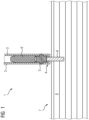
- FIG. 1 a sectional view of a roller blind device 1 according to the invention is shown.
- the roller blind device 1 has a first roller blind profile 2 and a second roller blind profile 3 .
- the first roller blind profile 2 is arranged opposite the second roller blind profile 3 .
- a roller blind guide 4 is provided at an axial end of the first roller blind profile 2 and the second roller blind profile 3 . This is formed by means of the first blind profile 2 and the second blind profile 3 in the form of a U-profile.
- a guide roller 5 is arranged between the two legs of this formed by the first blind profile 2 and the second blind profile 3 U-profile of the blind guide 4.
- the guide roller 5 has a shaft.
- the guide roller 5 is thus rotatably mounted.
- a roller carrier 6 supports the guide roller 5 . This is arranged between the first roller blind profile 2 and the second roller blind profile 3 in a space-saving manner.
- the galley according to the invention also has a counter unit 7 .
- This counter unit 7 has a counter 8 and a counter guide profile 9 .
- the counter guide profile 9 is designed to be at least partially embedded in the counter 8 . In order to ensure a stable anchoring of the bar guide profile 9 in the bar 7, the following construction is preferred.
- the bar guide profile 9 is let into the bar 8 over a larger section of its length than it projects beyond.
- the counter guide profile 9 protrudes in a direction perpendicular to the counter 8.
- roller blind guide 4 formed from the U-profile of the first roller blind profile 2 and the second roller blind profile 3 to grip around the counter guide profile 9 .
- the guide roller 5 arranged within the roller blind guide 4 can thus interact with the counter guide profile 9 .
- the guide roller 5 touches down on the counter guide profile 9 and rolls on it.
- the roller blind guide 4 can be moved along the counter guide profile 9 .
- the end of the counter guide profile 9, on which the guide roller 5 rests, will then be rounded.
- good (low-friction) running properties of the guide roller 5 on the counter guide profile 9 are achieved.
- the bar guide profile 9 will extend over the entire length of the bar 8 or at least over a large part of the bar 8 . On the one hand, this means that the galley can be closed well over the entire length of the counter 8 by means of the roller blind device 1 . On the other hand, the counter guide profile 9 also forms a snaking edge. This prevents liquids spilled on the counter 8 from running down the counter 8 .
- the bar guide profile 9 can be formed from flat steel.
- the guide roller 5 can be formed from a plastic. Overall, the features now described allow the guide roller 5 to roll off the counter guide profile 9 largely without friction. The galley can be closed easily.
- Both the guide roller 5 and the roller carrier 6 are between the first roller blind profile 2 and the second roller blind profile 3 arranged within the U-shaped roller blind guide 4 .
- the components that are present anyway can accommodate the components necessary for guiding the roller blind guide 4 .
- the present invention dispenses with guide profiles embedded in the counter 8 in a U-shape. This means that dirt and/or leftover food cannot accumulate in these profiles.
- the galley according to the invention or its roller blind device 1 is easy to keep clean and to clean. Due to the design of the roller blind guide 4 in the form of a U-profile, dirt that has penetrated the roller blind guide 4 can simply fall out of it or be removed. It can be prevented that the galley can no longer be properly closed due to dirt.
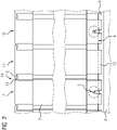
- FIG 2 a schematic partial view of a galley according to the invention is shown.
- This comprises a first supporting slat unit 10 which is arranged adjacent to a supported slat unit 11 .
- the supported slat unit 11 is in turn arranged next to a second load-bearing slat unit 12 .
- the roller blind device 1 is therefore constructed in a modular manner from alternatingly arranged load-bearing slat units 10, 12 and supported slat units 11. With this design, guide rollers 5 can be saved. The number of moving parts of the roller blind device 1 is reduced.
- the roller blind device 1 is easier to maintain and less prone to errors. It is also cheaper to produce.
- first support device 14 The attachment of the supported lamellar unit 11 to the supporting lamellar units 10, 12 can take place via a first support device 14.
- this has a first web 16 and a second web 17 in each case.
- the first ridge 16 is formed on the supported fin unit 11; the second web 17 is formed on the second load-bearing lamella unit 12 .
- the first web 16 and the second web 17 are in engagement with each other.
- the first web 16 rests on the second web 17 . He can be connected to this, for example, by gluing.
- the supported slat unit 11 is supported by the first supporting slat unit 10 and the second supporting slat unit 12 . Accordingly, a roller blind guide 4 can be dispensed with in the supported slat unit 10 .
- the first support device 14 is also arranged on a side of the blind guide 4 facing away from the counter 8 .
- the supported lamellar unit 11 is thus, as it were, "hooked" into the load-bearing lamellar units 10, 12.
- FIG 3 a further schematic partial view of a galley according to the invention is shown.
- a second support device 15 is provided. This is arranged on a side of the counter 8 facing the roller blind guide 4 .
- the second support device 15 also has a first web 16 and a second web 17 in each case. Again, the first ridge 16 and the second ridge 17 engage with each other.
- the first web 16 is arranged on the second web 17 .
- the supported slat unit 10 is, as it were, "supported” on the supporting slat units 10,12.
- the first web 16 can in turn be held in engagement with the second web 17 by gluing, for example.
- Both the first support device 14 and the second support device 15 can now be provided in the roller blind device 1 at the same time.
- the number of support devices 14, 15 can be designed to be redundant. Even if one of the support devices 14, 15 fails, the remaining intact support device 15, 14 can at least partially continue to function until a repair is made take over. A reliable function of the roller blind device 1 is guaranteed.
- the galley according to the invention can be used on board high-speed trains, for example. It is particularly easy to clean and keep clean. Overall, the galley is less sensitive to dirt of all kinds.
Landscapes
- Engineering & Computer Science (AREA)
- Structural Engineering (AREA)
- Physics & Mathematics (AREA)
- Thermal Sciences (AREA)
- Architecture (AREA)
- Civil Engineering (AREA)
- Operating, Guiding And Securing Of Roll- Type Closing Members (AREA)
- Table Devices Or Equipment (AREA)
Claims (8)
- Placard, comprenant- un système (1) à store comprenant au moins une unité (10, 12) de lamelles portantes, un premier profilé (2) de store et un deuxième profilé (3) de store opposé et au moins un guidage (4) de store ; et- une unité (7) de présentoir, comprenant un présentoir (8) et un profilé (9) de guidage de présentoir, qui coopère avec le guidage (4) de store pour guider l'unité (10, 12) à lamelles portantes ; et- dans lequel le guidage (4) de store peut être déplacé dans une direction horizontale du présentoir (8) par rapport au profilé (9) de guidage de présentoir ;- dans lequel le guidage (4) de store englobe le profilé (9) de guidage de présentoir disposé au moins en partie au-dessus du présentoir (8) ;- dans lequel le premier profilé (2) de store et le deuxième profilé (3) de store opposé sont constitués avec le guidage (4) de store sous la forme d'un profilé en U,caractérisé en ce que
le guidage (4) de store a au moins un galet (5) de guidage, qui est disposé entre le premier profilé (2) de store et le deuxième profilé (3) de store et qui coopère avec le profilé (9) de guidage de présentoir. - Placard suivant la revendication 1, dans lequel un support (6) de galet pour porter le galet (5) de guidage est disposé d'un côté, non tourné vers le profilé (9) de guidage de présentoir, du galet (5) de guidage.
- Placard suivant l'une des revendications 1 ou 2, dans lequel le profilé (9) de guidage de présentoir est encastré au moins en partie dans le présentoir (8).
- Placard suivant l'une des revendications 1 à 3, dans lequel le profilé (9) de guidage de présentoir est en un acier plat, qui est arrondi à une extrémité tournée vers le profilé (2, 3) de store.
- Placard suivant l'une des revendications 1 à 4, dans lequel au moins une unité (11) à lamelles soutenue est disposée entre deux unités (10, 12) à lamelles portantes et a au moins un troisième profilé (13) de store.
- Placard suivant la revendication 5, dans lequel le troisième profilé (13) de store est d'un côté, tourné vers le présentoir (8), mis en prise, au moyen d'un premier dispositif (14) de soutien, pour soutenir l'unité (11) à lamelles soutenue, avec les deux unités (10, 12) à lamelles portantes.
- Placard suivant l'une des revendications 5 ou 6, dans lequel le troisième profilé (13) de store est du côté, non tourné vers le présentoir (8), mis en prise, au moyen d'un deuxième dispositif (15) de soutien pour le soutien de l'unité (11) à lamelles soutenue, avec les deux unités (10, 12) à lamelles portantes.
- Placard suivant l'une des revendications 6 ou 7, dans lequel le premier dispositif (14) de soutien et/ou le deuxième dispositif (15) de soutien a au moins un premier rebord (16), qui est constitué sur le troisième profilé (13) de store et qui est en prise avec au moins un deuxième rebord (17), qui est constitué sur le premier profilé (2) de store et/ou le deuxième profilé (3) de store et/ou le guidage (4) de store.
Applications Claiming Priority (2)
| Application Number | Priority Date | Filing Date | Title |
|---|---|---|---|
| DE102018206730.9A DE102018206730A1 (de) | 2018-05-02 | 2018-05-02 | Galley |
| PCT/EP2019/060317 WO2019211119A1 (fr) | 2018-05-02 | 2019-04-23 | Placard |
Publications (2)
| Publication Number | Publication Date |
|---|---|
| EP3758558A1 EP3758558A1 (fr) | 2021-01-06 |
| EP3758558B1 true EP3758558B1 (fr) | 2023-02-15 |
Family
ID=66529960
Family Applications (1)
| Application Number | Title | Priority Date | Filing Date |
|---|---|---|---|
| EP19723663.1A Active EP3758558B1 (fr) | 2018-05-02 | 2019-04-23 | Placard |
Country Status (6)
| Country | Link |
|---|---|
| EP (1) | EP3758558B1 (fr) |
| CN (1) | CN215502210U (fr) |
| DE (1) | DE102018206730A1 (fr) |
| ES (1) | ES2943509T3 (fr) |
| RU (1) | RU203397U1 (fr) |
| WO (1) | WO2019211119A1 (fr) |
Families Citing this family (1)
| Publication number | Priority date | Publication date | Assignee | Title |
|---|---|---|---|---|
| DE102023209393B4 (de) | 2023-09-26 | 2025-05-08 | Siemens Mobility GmbH | Horizontal geführtes Rollo für eine Galley eines Schienenfahrzeugs mit verdeckter unterer Führungsschiene |
Family Cites Families (7)
| Publication number | Priority date | Publication date | Assignee | Title |
|---|---|---|---|---|
| NL8402350A (nl) * | 1984-07-26 | 1986-02-17 | Assenburg Bv | Roldeur, rolluik of dergelijke. |
| DE8520090U1 (de) * | 1985-07-11 | 1985-09-26 | Wilkhahn Wilkening + Hahne GmbH + Co, 3252 Bad Münder | Schrankartiger Behälter |
| JP2001199399A (ja) * | 2000-01-20 | 2001-07-24 | Jamco Corp | 航空機用ギャレイユニット |
| JP3970825B2 (ja) * | 2003-10-02 | 2007-09-05 | 株式会社ジャムコ | 航空機用ギャレー |
| RU2412868C2 (ru) * | 2006-02-24 | 2011-02-27 | Эирбус Дойчланд Гмбх | Бортовая кухня и способ обеспечения питанием пассажиров воздушного судна |
| WO2008111934A1 (fr) * | 2007-03-12 | 2008-09-18 | Beverage-Air Corporation | Appareil de préparation alimentaire avec couvercle coulissant |
| US11072426B2 (en) * | 2015-11-23 | 2021-07-27 | The Boeing Company | Galley system of an aircraft |
-
2018
- 2018-05-02 DE DE102018206730.9A patent/DE102018206730A1/de not_active Withdrawn
-
2019
- 2019-04-23 RU RU2020135923U patent/RU203397U1/ru active
- 2019-04-23 EP EP19723663.1A patent/EP3758558B1/fr active Active
- 2019-04-23 ES ES19723663T patent/ES2943509T3/es active Active
- 2019-04-23 WO PCT/EP2019/060317 patent/WO2019211119A1/fr not_active Ceased
- 2019-04-23 CN CN201990000690.7U patent/CN215502210U/zh active Active
Also Published As
| Publication number | Publication date |
|---|---|
| WO2019211119A1 (fr) | 2019-11-07 |
| EP3758558A1 (fr) | 2021-01-06 |
| DE102018206730A1 (de) | 2019-11-07 |
| RU203397U1 (ru) | 2021-04-02 |
| CN215502210U (zh) | 2022-01-14 |
| ES2943509T3 (es) | 2023-06-13 |
Similar Documents
| Publication | Publication Date | Title |
|---|---|---|
| DE19547049C2 (de) | Auszugsperre für übereinander angeordnete Schubladen | |
| DE3014276A1 (de) | Fuehrung fuer einen an einem tisch o.dgl. angebrachten auszug | |
| AT509540A1 (de) | Ausziehführung für schubladen | |
| WO2011137545A9 (fr) | Déverrouillage d'une porte palière d'un ascenseur | |
| DE3049241A1 (de) | Gleitschienenfuehrung fuer fahrzeugsitze | |
| EP3875717B1 (fr) | Rail de roulement sous la forme de profilé en tôle laminée | |
| DE10225360C1 (de) | Rollo mit seitlicher Führung | |
| AT517479B1 (de) | Schubladenausziehführung | |
| EP4110138B1 (fr) | Guide coulissant | |
| DE60114735T2 (de) | Reinigungsvorrichtung zur wahlweisen Reinigung von zwei oder mehreren Zylindern in einer Druckmaschine, mit einer einzigen Reinigungsvorrichtung | |
| EP2026437A1 (fr) | Dispositif à chaîne de guidage d'énergie | |
| DE202010009390U1 (de) | Palette | |
| DE102010010719B4 (de) | Fensterbetätigungsvorrichtung | |
| EP3758558A1 (fr) | Placard | |
| DE69012787T2 (de) | Lagebremse für Schiebetüren. | |
| DE2717152C3 (de) | Auszugsperre für ein mehrere übereinander angeordnete Schubkästen aufweisendes Möbelstück | |
| AT501777A2 (de) | Schubladenführung | |
| DE102016110950B3 (de) | Vorrichtung zur Umlenkung von Schubketten und Schubkette | |
| AT393070B (de) | Schubladenauszug nach differentialbauart | |
| DE29921294U1 (de) | Schrankmöbel mit einer Jalousie | |
| EP4179228B1 (fr) | Support pour une chaîne d'alimentation en énergie | |
| DE29810728U1 (de) | Dreileistenhärtereglerarretierung für Lattenroste und Betten | |
| EP1726560A1 (fr) | Table élévatrice à ciseaux | |
| DE102009025331A1 (de) | Dachstruktur für ein Kraftfahrzeug | |
| DE9406570U1 (de) | Vorrichtung zur Leitungsführung |
Legal Events
| Date | Code | Title | Description |
|---|---|---|---|
| STAA | Information on the status of an ep patent application or granted ep patent |
Free format text: STATUS: UNKNOWN |
|
| STAA | Information on the status of an ep patent application or granted ep patent |
Free format text: STATUS: THE INTERNATIONAL PUBLICATION HAS BEEN MADE |
|
| PUAI | Public reference made under article 153(3) epc to a published international application that has entered the european phase |
Free format text: ORIGINAL CODE: 0009012 |
|
| STAA | Information on the status of an ep patent application or granted ep patent |
Free format text: STATUS: REQUEST FOR EXAMINATION WAS MADE |
|
| 17P | Request for examination filed |
Effective date: 20201002 |
|
| AK | Designated contracting states |
Kind code of ref document: A1 Designated state(s): AL AT BE BG CH CY CZ DE DK EE ES FI FR GB GR HR HU IE IS IT LI LT LU LV MC MK MT NL NO PL PT RO RS SE SI SK SM TR |
|
| AX | Request for extension of the european patent |
Extension state: BA ME |
|
| DAV | Request for validation of the european patent (deleted) | ||
| DAX | Request for extension of the european patent (deleted) | ||
| GRAP | Despatch of communication of intention to grant a patent |
Free format text: ORIGINAL CODE: EPIDOSNIGR1 |
|
| STAA | Information on the status of an ep patent application or granted ep patent |
Free format text: STATUS: GRANT OF PATENT IS INTENDED |
|
| INTG | Intention to grant announced |
Effective date: 20221012 |
|
| GRAS | Grant fee paid |
Free format text: ORIGINAL CODE: EPIDOSNIGR3 |
|
| GRAA | (expected) grant |
Free format text: ORIGINAL CODE: 0009210 |
|
| STAA | Information on the status of an ep patent application or granted ep patent |
Free format text: STATUS: THE PATENT HAS BEEN GRANTED |
|
| AK | Designated contracting states |
Kind code of ref document: B1 Designated state(s): AL AT BE BG CH CY CZ DE DK EE ES FI FR GB GR HR HU IE IS IT LI LT LU LV MC MK MT NL NO PL PT RO RS SE SI SK SM TR |
|
| REG | Reference to a national code |
Ref country code: CH Ref legal event code: EP Ref country code: GB Ref legal event code: FG4D Free format text: NOT ENGLISH |
|
| REG | Reference to a national code |
Ref country code: DE Ref legal event code: R096 Ref document number: 502019006996 Country of ref document: DE |
|
| REG | Reference to a national code |
Ref country code: AT Ref legal event code: REF Ref document number: 1547796 Country of ref document: AT Kind code of ref document: T Effective date: 20230315 Ref country code: IE Ref legal event code: FG4D Free format text: LANGUAGE OF EP DOCUMENT: GERMAN |
|
| REG | Reference to a national code |
Ref country code: LT Ref legal event code: MG9D |
|
| REG | Reference to a national code |
Ref country code: ES Ref legal event code: FG2A Ref document number: 2943509 Country of ref document: ES Kind code of ref document: T3 Effective date: 20230613 |
|
| REG | Reference to a national code |
Ref country code: NL Ref legal event code: MP Effective date: 20230215 |
|
| PG25 | Lapsed in a contracting state [announced via postgrant information from national office to epo] |
Ref country code: RS Free format text: LAPSE BECAUSE OF FAILURE TO SUBMIT A TRANSLATION OF THE DESCRIPTION OR TO PAY THE FEE WITHIN THE PRESCRIBED TIME-LIMIT Effective date: 20230215 Ref country code: PT Free format text: LAPSE BECAUSE OF FAILURE TO SUBMIT A TRANSLATION OF THE DESCRIPTION OR TO PAY THE FEE WITHIN THE PRESCRIBED TIME-LIMIT Effective date: 20230615 Ref country code: NO Free format text: LAPSE BECAUSE OF FAILURE TO SUBMIT A TRANSLATION OF THE DESCRIPTION OR TO PAY THE FEE WITHIN THE PRESCRIBED TIME-LIMIT Effective date: 20230515 Ref country code: NL Free format text: LAPSE BECAUSE OF FAILURE TO SUBMIT A TRANSLATION OF THE DESCRIPTION OR TO PAY THE FEE WITHIN THE PRESCRIBED TIME-LIMIT Effective date: 20230215 Ref country code: LV Free format text: LAPSE BECAUSE OF FAILURE TO SUBMIT A TRANSLATION OF THE DESCRIPTION OR TO PAY THE FEE WITHIN THE PRESCRIBED TIME-LIMIT Effective date: 20230215 Ref country code: LT Free format text: LAPSE BECAUSE OF FAILURE TO SUBMIT A TRANSLATION OF THE DESCRIPTION OR TO PAY THE FEE WITHIN THE PRESCRIBED TIME-LIMIT Effective date: 20230215 Ref country code: HR Free format text: LAPSE BECAUSE OF FAILURE TO SUBMIT A TRANSLATION OF THE DESCRIPTION OR TO PAY THE FEE WITHIN THE PRESCRIBED TIME-LIMIT Effective date: 20230215 |
|
| PG25 | Lapsed in a contracting state [announced via postgrant information from national office to epo] |
Ref country code: SE Free format text: LAPSE BECAUSE OF FAILURE TO SUBMIT A TRANSLATION OF THE DESCRIPTION OR TO PAY THE FEE WITHIN THE PRESCRIBED TIME-LIMIT Effective date: 20230215 Ref country code: PL Free format text: LAPSE BECAUSE OF FAILURE TO SUBMIT A TRANSLATION OF THE DESCRIPTION OR TO PAY THE FEE WITHIN THE PRESCRIBED TIME-LIMIT Effective date: 20230215 Ref country code: IS Free format text: LAPSE BECAUSE OF FAILURE TO SUBMIT A TRANSLATION OF THE DESCRIPTION OR TO PAY THE FEE WITHIN THE PRESCRIBED TIME-LIMIT Effective date: 20230615 Ref country code: GR Free format text: LAPSE BECAUSE OF FAILURE TO SUBMIT A TRANSLATION OF THE DESCRIPTION OR TO PAY THE FEE WITHIN THE PRESCRIBED TIME-LIMIT Effective date: 20230516 Ref country code: FI Free format text: LAPSE BECAUSE OF FAILURE TO SUBMIT A TRANSLATION OF THE DESCRIPTION OR TO PAY THE FEE WITHIN THE PRESCRIBED TIME-LIMIT Effective date: 20230215 |
|
| PG25 | Lapsed in a contracting state [announced via postgrant information from national office to epo] |
Ref country code: SM Free format text: LAPSE BECAUSE OF FAILURE TO SUBMIT A TRANSLATION OF THE DESCRIPTION OR TO PAY THE FEE WITHIN THE PRESCRIBED TIME-LIMIT Effective date: 20230215 Ref country code: RO Free format text: LAPSE BECAUSE OF FAILURE TO SUBMIT A TRANSLATION OF THE DESCRIPTION OR TO PAY THE FEE WITHIN THE PRESCRIBED TIME-LIMIT Effective date: 20230215 Ref country code: EE Free format text: LAPSE BECAUSE OF FAILURE TO SUBMIT A TRANSLATION OF THE DESCRIPTION OR TO PAY THE FEE WITHIN THE PRESCRIBED TIME-LIMIT Effective date: 20230215 Ref country code: DK Free format text: LAPSE BECAUSE OF FAILURE TO SUBMIT A TRANSLATION OF THE DESCRIPTION OR TO PAY THE FEE WITHIN THE PRESCRIBED TIME-LIMIT Effective date: 20230215 Ref country code: CZ Free format text: LAPSE BECAUSE OF FAILURE TO SUBMIT A TRANSLATION OF THE DESCRIPTION OR TO PAY THE FEE WITHIN THE PRESCRIBED TIME-LIMIT Effective date: 20230215 |
|
| REG | Reference to a national code |
Ref country code: DE Ref legal event code: R097 Ref document number: 502019006996 Country of ref document: DE |
|
| PG25 | Lapsed in a contracting state [announced via postgrant information from national office to epo] |
Ref country code: SK Free format text: LAPSE BECAUSE OF FAILURE TO SUBMIT A TRANSLATION OF THE DESCRIPTION OR TO PAY THE FEE WITHIN THE PRESCRIBED TIME-LIMIT Effective date: 20230215 |
|
| REG | Reference to a national code |
Ref country code: CH Ref legal event code: PL |
|
| PLBE | No opposition filed within time limit |
Free format text: ORIGINAL CODE: 0009261 |
|
| STAA | Information on the status of an ep patent application or granted ep patent |
Free format text: STATUS: NO OPPOSITION FILED WITHIN TIME LIMIT |
|
| PG25 | Lapsed in a contracting state [announced via postgrant information from national office to epo] |
Ref country code: LU Free format text: LAPSE BECAUSE OF NON-PAYMENT OF DUE FEES Effective date: 20230423 |
|
| REG | Reference to a national code |
Ref country code: BE Ref legal event code: MM Effective date: 20230430 |
|
| PG25 | Lapsed in a contracting state [announced via postgrant information from national office to epo] |
Ref country code: MC Free format text: LAPSE BECAUSE OF FAILURE TO SUBMIT A TRANSLATION OF THE DESCRIPTION OR TO PAY THE FEE WITHIN THE PRESCRIBED TIME-LIMIT Effective date: 20230215 |
|
| 26N | No opposition filed |
Effective date: 20231116 |
|
| PG25 | Lapsed in a contracting state [announced via postgrant information from national office to epo] |
Ref country code: SI Free format text: LAPSE BECAUSE OF FAILURE TO SUBMIT A TRANSLATION OF THE DESCRIPTION OR TO PAY THE FEE WITHIN THE PRESCRIBED TIME-LIMIT Effective date: 20230215 Ref country code: MC Free format text: LAPSE BECAUSE OF FAILURE TO SUBMIT A TRANSLATION OF THE DESCRIPTION OR TO PAY THE FEE WITHIN THE PRESCRIBED TIME-LIMIT Effective date: 20230215 Ref country code: LI Free format text: LAPSE BECAUSE OF NON-PAYMENT OF DUE FEES Effective date: 20230430 Ref country code: CH Free format text: LAPSE BECAUSE OF NON-PAYMENT OF DUE FEES Effective date: 20230430 |
|
| REG | Reference to a national code |
Ref country code: IE Ref legal event code: MM4A |
|
| PG25 | Lapsed in a contracting state [announced via postgrant information from national office to epo] |
Ref country code: BE Free format text: LAPSE BECAUSE OF NON-PAYMENT OF DUE FEES Effective date: 20230430 |
|
| PG25 | Lapsed in a contracting state [announced via postgrant information from national office to epo] |
Ref country code: IE Free format text: LAPSE BECAUSE OF NON-PAYMENT OF DUE FEES Effective date: 20230423 |
|
| PG25 | Lapsed in a contracting state [announced via postgrant information from national office to epo] |
Ref country code: IE Free format text: LAPSE BECAUSE OF NON-PAYMENT OF DUE FEES Effective date: 20230423 |
|
| PG25 | Lapsed in a contracting state [announced via postgrant information from national office to epo] |
Ref country code: BG Free format text: LAPSE BECAUSE OF FAILURE TO SUBMIT A TRANSLATION OF THE DESCRIPTION OR TO PAY THE FEE WITHIN THE PRESCRIBED TIME-LIMIT Effective date: 20230215 |
|
| PG25 | Lapsed in a contracting state [announced via postgrant information from national office to epo] |
Ref country code: BG Free format text: LAPSE BECAUSE OF FAILURE TO SUBMIT A TRANSLATION OF THE DESCRIPTION OR TO PAY THE FEE WITHIN THE PRESCRIBED TIME-LIMIT Effective date: 20230215 |
|
| REG | Reference to a national code |
Ref country code: AT Ref legal event code: MM01 Ref document number: 1547796 Country of ref document: AT Kind code of ref document: T Effective date: 20240423 |
|
| PGFP | Annual fee paid to national office [announced via postgrant information from national office to epo] |
Ref country code: DE Payment date: 20250620 Year of fee payment: 7 |
|
| PGFP | Annual fee paid to national office [announced via postgrant information from national office to epo] |
Ref country code: GB Payment date: 20250507 Year of fee payment: 7 |
|
| PGFP | Annual fee paid to national office [announced via postgrant information from national office to epo] |
Ref country code: IT Payment date: 20250417 Year of fee payment: 7 |
|
| PGFP | Annual fee paid to national office [announced via postgrant information from national office to epo] |
Ref country code: FR Payment date: 20250411 Year of fee payment: 7 |
|
| PG25 | Lapsed in a contracting state [announced via postgrant information from national office to epo] |
Ref country code: AT Free format text: LAPSE BECAUSE OF NON-PAYMENT OF DUE FEES Effective date: 20240423 |
|
| PG25 | Lapsed in a contracting state [announced via postgrant information from national office to epo] |
Ref country code: CY Free format text: LAPSE BECAUSE OF FAILURE TO SUBMIT A TRANSLATION OF THE DESCRIPTION OR TO PAY THE FEE WITHIN THE PRESCRIBED TIME-LIMIT; INVALID AB INITIO Effective date: 20190423 |
|
| PG25 | Lapsed in a contracting state [announced via postgrant information from national office to epo] |
Ref country code: HU Free format text: LAPSE BECAUSE OF FAILURE TO SUBMIT A TRANSLATION OF THE DESCRIPTION OR TO PAY THE FEE WITHIN THE PRESCRIBED TIME-LIMIT; INVALID AB INITIO Effective date: 20190423 |
|
| REG | Reference to a national code |
Ref country code: DE Ref legal event code: R081 Ref document number: 502019006996 Country of ref document: DE Owner name: SIEMENS MOBILITY GMBH, DE Free format text: FORMER OWNER: SIEMENS MOBILITY GMBH, 81739 MUENCHEN, DE |
|
| PGFP | Annual fee paid to national office [announced via postgrant information from national office to epo] |
Ref country code: ES Payment date: 20250721 Year of fee payment: 7 |
|
| PG25 | Lapsed in a contracting state [announced via postgrant information from national office to epo] |
Ref country code: TR Free format text: LAPSE BECAUSE OF FAILURE TO SUBMIT A TRANSLATION OF THE DESCRIPTION OR TO PAY THE FEE WITHIN THE PRESCRIBED TIME-LIMIT Effective date: 20230215 |
|
| PGFP | Annual fee paid to national office [announced via postgrant information from national office to epo] |
Ref country code: AT Payment date: 20260410 Year of fee payment: 5 |