EP3759408B1 - Réfrigérateur et son procédé de commande - Google Patents
Réfrigérateur et son procédé de commande Download PDFInfo
- Publication number
- EP3759408B1 EP3759408B1 EP18906773.9A EP18906773A EP3759408B1 EP 3759408 B1 EP3759408 B1 EP 3759408B1 EP 18906773 A EP18906773 A EP 18906773A EP 3759408 B1 EP3759408 B1 EP 3759408B1
- Authority
- EP
- European Patent Office
- Prior art keywords
- evaporator
- defrosting
- temperature
- hole
- storage compartment
- Prior art date
- Legal status (The legal status is an assumption and is not a legal conclusion. Google has not performed a legal analysis and makes no representation as to the accuracy of the status listed.)
- Active
Links
Images




Classifications
-
- F—MECHANICAL ENGINEERING; LIGHTING; HEATING; WEAPONS; BLASTING
- F25—REFRIGERATION OR COOLING; COMBINED HEATING AND REFRIGERATION SYSTEMS; HEAT PUMP SYSTEMS; MANUFACTURE OR STORAGE OF ICE; LIQUEFACTION SOLIDIFICATION OF GASES
- F25D—REFRIGERATORS; COLD ROOMS; ICE-BOXES; COOLING OR FREEZING APPARATUS NOT OTHERWISE PROVIDED FOR
- F25D29/00—Arrangement or mounting of control or safety devices
-
- F—MECHANICAL ENGINEERING; LIGHTING; HEATING; WEAPONS; BLASTING
- F25—REFRIGERATION OR COOLING; COMBINED HEATING AND REFRIGERATION SYSTEMS; HEAT PUMP SYSTEMS; MANUFACTURE OR STORAGE OF ICE; LIQUEFACTION SOLIDIFICATION OF GASES
- F25D—REFRIGERATORS; COLD ROOMS; ICE-BOXES; COOLING OR FREEZING APPARATUS NOT OTHERWISE PROVIDED FOR
- F25D17/00—Arrangements for circulating cooling fluids; Arrangements for circulating gas, e.g. air, within refrigerated spaces
- F25D17/04—Arrangements for circulating cooling fluids; Arrangements for circulating gas, e.g. air, within refrigerated spaces for circulating air, e.g. by convection
- F25D17/06—Arrangements for circulating cooling fluids; Arrangements for circulating gas, e.g. air, within refrigerated spaces for circulating air, e.g. by convection by forced circulation
- F25D17/062—Arrangements for circulating cooling fluids; Arrangements for circulating gas, e.g. air, within refrigerated spaces for circulating air, e.g. by convection by forced circulation in household refrigerators
-
- F—MECHANICAL ENGINEERING; LIGHTING; HEATING; WEAPONS; BLASTING
- F25—REFRIGERATION OR COOLING; COMBINED HEATING AND REFRIGERATION SYSTEMS; HEAT PUMP SYSTEMS; MANUFACTURE OR STORAGE OF ICE; LIQUEFACTION SOLIDIFICATION OF GASES
- F25B—REFRIGERATION MACHINES, PLANTS OR SYSTEMS; COMBINED HEATING AND REFRIGERATION SYSTEMS; HEAT PUMP SYSTEMS
- F25B49/00—Arrangement or mounting of control or safety devices
- F25B49/02—Arrangement or mounting of control or safety devices for compression type machines, plants or systems
- F25B49/022—Compressor control arrangements
-
- F—MECHANICAL ENGINEERING; LIGHTING; HEATING; WEAPONS; BLASTING
- F25—REFRIGERATION OR COOLING; COMBINED HEATING AND REFRIGERATION SYSTEMS; HEAT PUMP SYSTEMS; MANUFACTURE OR STORAGE OF ICE; LIQUEFACTION SOLIDIFICATION OF GASES
- F25D—REFRIGERATORS; COLD ROOMS; ICE-BOXES; COOLING OR FREEZING APPARATUS NOT OTHERWISE PROVIDED FOR
- F25D17/00—Arrangements for circulating cooling fluids; Arrangements for circulating gas, e.g. air, within refrigerated spaces
- F25D17/04—Arrangements for circulating cooling fluids; Arrangements for circulating gas, e.g. air, within refrigerated spaces for circulating air, e.g. by convection
- F25D17/06—Arrangements for circulating cooling fluids; Arrangements for circulating gas, e.g. air, within refrigerated spaces for circulating air, e.g. by convection by forced circulation
-
- F—MECHANICAL ENGINEERING; LIGHTING; HEATING; WEAPONS; BLASTING
- F25—REFRIGERATION OR COOLING; COMBINED HEATING AND REFRIGERATION SYSTEMS; HEAT PUMP SYSTEMS; MANUFACTURE OR STORAGE OF ICE; LIQUEFACTION SOLIDIFICATION OF GASES
- F25D—REFRIGERATORS; COLD ROOMS; ICE-BOXES; COOLING OR FREEZING APPARATUS NOT OTHERWISE PROVIDED FOR
- F25D21/00—Defrosting; Preventing frosting; Removing condensed or defrost water
- F25D21/002—Defroster control
-
- F—MECHANICAL ENGINEERING; LIGHTING; HEATING; WEAPONS; BLASTING
- F25—REFRIGERATION OR COOLING; COMBINED HEATING AND REFRIGERATION SYSTEMS; HEAT PUMP SYSTEMS; MANUFACTURE OR STORAGE OF ICE; LIQUEFACTION SOLIDIFICATION OF GASES
- F25D—REFRIGERATORS; COLD ROOMS; ICE-BOXES; COOLING OR FREEZING APPARATUS NOT OTHERWISE PROVIDED FOR
- F25D21/00—Defrosting; Preventing frosting; Removing condensed or defrost water
- F25D21/002—Defroster control
- F25D21/006—Defroster control with electronic control circuits
-
- F—MECHANICAL ENGINEERING; LIGHTING; HEATING; WEAPONS; BLASTING
- F25—REFRIGERATION OR COOLING; COMBINED HEATING AND REFRIGERATION SYSTEMS; HEAT PUMP SYSTEMS; MANUFACTURE OR STORAGE OF ICE; LIQUEFACTION SOLIDIFICATION OF GASES
- F25D—REFRIGERATORS; COLD ROOMS; ICE-BOXES; COOLING OR FREEZING APPARATUS NOT OTHERWISE PROVIDED FOR
- F25D21/00—Defrosting; Preventing frosting; Removing condensed or defrost water
- F25D21/02—Detecting the presence of frost or condensate
- F25D21/025—Detecting the presence of frost or condensate using air pressure differential detectors
-
- F—MECHANICAL ENGINEERING; LIGHTING; HEATING; WEAPONS; BLASTING
- F25—REFRIGERATION OR COOLING; COMBINED HEATING AND REFRIGERATION SYSTEMS; HEAT PUMP SYSTEMS; MANUFACTURE OR STORAGE OF ICE; LIQUEFACTION SOLIDIFICATION OF GASES
- F25D—REFRIGERATORS; COLD ROOMS; ICE-BOXES; COOLING OR FREEZING APPARATUS NOT OTHERWISE PROVIDED FOR
- F25D21/00—Defrosting; Preventing frosting; Removing condensed or defrost water
- F25D21/06—Removing frost
- F25D21/08—Removing frost by electric heating
-
- F—MECHANICAL ENGINEERING; LIGHTING; HEATING; WEAPONS; BLASTING
- F25—REFRIGERATION OR COOLING; COMBINED HEATING AND REFRIGERATION SYSTEMS; HEAT PUMP SYSTEMS; MANUFACTURE OR STORAGE OF ICE; LIQUEFACTION SOLIDIFICATION OF GASES
- F25B—REFRIGERATION MACHINES, PLANTS OR SYSTEMS; COMBINED HEATING AND REFRIGERATION SYSTEMS; HEAT PUMP SYSTEMS
- F25B1/00—Compression machines, plants or systems with non-reversible cycle
-
- F—MECHANICAL ENGINEERING; LIGHTING; HEATING; WEAPONS; BLASTING
- F25—REFRIGERATION OR COOLING; COMBINED HEATING AND REFRIGERATION SYSTEMS; HEAT PUMP SYSTEMS; MANUFACTURE OR STORAGE OF ICE; LIQUEFACTION SOLIDIFICATION OF GASES
- F25B—REFRIGERATION MACHINES, PLANTS OR SYSTEMS; COMBINED HEATING AND REFRIGERATION SYSTEMS; HEAT PUMP SYSTEMS
- F25B2600/00—Control issues
- F25B2600/11—Fan speed control
- F25B2600/112—Fan speed control of evaporator fans
-
- F—MECHANICAL ENGINEERING; LIGHTING; HEATING; WEAPONS; BLASTING
- F25—REFRIGERATION OR COOLING; COMBINED HEATING AND REFRIGERATION SYSTEMS; HEAT PUMP SYSTEMS; MANUFACTURE OR STORAGE OF ICE; LIQUEFACTION SOLIDIFICATION OF GASES
- F25B—REFRIGERATION MACHINES, PLANTS OR SYSTEMS; COMBINED HEATING AND REFRIGERATION SYSTEMS; HEAT PUMP SYSTEMS
- F25B2700/00—Sensing or detecting of parameters; Sensors therefor
- F25B2700/19—Pressures
-
- F—MECHANICAL ENGINEERING; LIGHTING; HEATING; WEAPONS; BLASTING
- F25—REFRIGERATION OR COOLING; COMBINED HEATING AND REFRIGERATION SYSTEMS; HEAT PUMP SYSTEMS; MANUFACTURE OR STORAGE OF ICE; LIQUEFACTION SOLIDIFICATION OF GASES
- F25D—REFRIGERATORS; COLD ROOMS; ICE-BOXES; COOLING OR FREEZING APPARATUS NOT OTHERWISE PROVIDED FOR
- F25D2700/00—Means for sensing or measuring; Sensors therefor
- F25D2700/02—Sensors detecting door opening
-
- F—MECHANICAL ENGINEERING; LIGHTING; HEATING; WEAPONS; BLASTING
- F25—REFRIGERATION OR COOLING; COMBINED HEATING AND REFRIGERATION SYSTEMS; HEAT PUMP SYSTEMS; MANUFACTURE OR STORAGE OF ICE; LIQUEFACTION SOLIDIFICATION OF GASES
- F25D—REFRIGERATORS; COLD ROOMS; ICE-BOXES; COOLING OR FREEZING APPARATUS NOT OTHERWISE PROVIDED FOR
- F25D2700/00—Means for sensing or measuring; Sensors therefor
- F25D2700/10—Sensors measuring the temperature of the evaporator
-
- F—MECHANICAL ENGINEERING; LIGHTING; HEATING; WEAPONS; BLASTING
- F25—REFRIGERATION OR COOLING; COMBINED HEATING AND REFRIGERATION SYSTEMS; HEAT PUMP SYSTEMS; MANUFACTURE OR STORAGE OF ICE; LIQUEFACTION SOLIDIFICATION OF GASES
- F25D—REFRIGERATORS; COLD ROOMS; ICE-BOXES; COOLING OR FREEZING APPARATUS NOT OTHERWISE PROVIDED FOR
- F25D2700/00—Means for sensing or measuring; Sensors therefor
- F25D2700/12—Sensors measuring the inside temperature
Definitions
- Embodiments of the present disclosure relate to a refrigerator and a control method for the same, more particularly, a refrigerator having enhanced energy efficiency and a control method for the same.
- a freeze cycling mechanism is installed in the mechanical chamber of the refrigerator.
- the freeze cycling mechanism is configured to preserve foods fresh by keeping an inner space of the refrigerator on being in a freezer or refrigerator state, using a property of a refrigerant that absorbing external heat while a low-pressure liquid refrigerant is converted into a gas refrigerant.
- the compressor When the compressor is driving, the temperature of the evaporator falls and ice is stuck to the evaporator. Once more ice is stuck to the evaporator, heat-exchange efficiency between the evaporator and air deteriorates enough to make it difficult to chill and generate a sufficient cold air which is supplied to storage compartments. Accordingly, the compressor has to be driving more frequently for a longer time period, which is disadvantageous.
- Another object of the present invention is to provide a refrigerator which may perform a secondary defrosting process after a first defrosting process, unless the first defrosting process is performed sufficiently, and a controlling method for the same.
- the present invention also provides a refrigerator according to claim 12.
- the storage compartments 6 and 8 may include a first storage compartment 6 and a second storage compartment 8.
- the first and second storage compartments 6 and 8 may realize a refrigerator compartment and a freezer compartment, respectively, or vice versa.
- the first and second storage compartments 6 and 8 may realize one refrigerator or freezer compartment.
- An inlet pipe 30 is provided in the inlet hole 32 to guide the air into the case 35 such that an air channel may be formed by connecting the storage compartments 6 and 8 to the case 35.
- the evaporator 20 may be mounted in the case 35 and configured to generate cold air by vaporizing the refrigerant compressed by a compressor 60.
- the air inside the case 35 is chilled while exchanging heat with the evaporator 20.
- An evaporator temperature sensor 92 is provided in the evaporator 20 to measure the temperature of the evaporator 20.
- the evaporator temperature sensor 92 is able to sense a preset low temperature when the refrigerant penetrating the evaporator 20 is vaporized and a preset high temperature when the heater 50 is driving.
- the differential pressure sensor 100 includes a first through-hole 110 arranged between the evaporator 20 and the inlet hole 32; and a second through-hole 120 arranged between the evaporator 20 and the outlet hole 38.
- FIG. 4 is a control block diagram according to the present invention.
- the refrigerator includes a compressor 60 configured to compress a refrigerant.
- the control unit 96 is implemented to drive the compressor 60 when it is necessary to chill the storage compartments and supply a cold air to the storage compartment.
- the control unit 96 is provided with information about the driving of the compressor 60.
- a door switch 70 is provided to acquire information about the opening and closing of the door to open and close the storage compartments.
- a door switch 70 is provided in the doors, respectively, to sense whether the doors open or close the storage compartment, respectively.
- a timer 80 is provided to sense the elapsed time. The time measured by the timer 80 is transmitted to the control unit 96. For example, the control unit 96 acquires a signal indicating that the door 4 closed the storage compartment from the door switch 70 and it is then provided with information about the elapsed time after the door 4 closed the storage compartment by the timer 80.
- the information on the temperature of the storage compartment measured by the storage compartment temperature sensor 90 may be transmitted to the control unit 96.
- the information about the temperature of the storage compartment measured by the storage compartment temperature sensor 90 may be also transmitted to the control unit 96.
- the control unit 96 may end the defrosting for the evaporator according to the information about the temperature measured by the evaporator temperature sensor 92.
- the information measured by the differential pressure sensor 100 is transmitted to the control unit 96.
- the controlling method includes a step S40 of controlling one differential pressure sensor 100 to sense a difference between the pressures in the first through-hole 110 arranged between the inlet hole 32 for drawing air from the storage compartments 6 and 8 and the evaporator 20 and the second through-hole 120 arranged between the outlet hole 38 for discharging air into the storage compartments 6 and 8 and the evaporator 20; and a step of defrosting the evaporator by driving the heater 50 when the pressure difference is larger than a preset pressure.
- the pressure difference used in the present invention may mean a pressure difference value that is measured one time or an average of the pressure differences that is measured several times.
- the pressure measured by the differential pressure sensor 100 is likely to be calculated as an abnormal value by various external factors temporarily. In case of using the average of the pressure differences, the pressure difference measured by the differential pressure sensor 100 may become more reliable.
- the pressure difference measured by the differential pressure sensor 100 is larger than a preset pressure, it means that the pressure difference between the first through-hole 110 and the second through-hole 120 becomes larger.
- the larger pressure difference may mean that the amount of the ice formed on the evaporator 20 increases enough to makes it difficult for the evaporator 20 to perform heat-exchange. Accordingly, the cold air supply to the storage compartments 6 and 8 from the evaporator 20 cannot be performed smoothly such that the defrosting may be needed.
- the differential pressure sensor 100 may not measure the pressure difference.
- the door switch 70 may determine whether a preset time period elapses after the door 4 closes the storage compartments 6 and 8. Unless the preset time period elapses, the differential pressure sensor 100 may not measure the pressure difference S30. It is also possible for the door switch 70 to determine the door 4 is closed before the timer 80 measures the elapsed time and the elapsed time may be measured after that. At this time, the elapsed time may mean approximately 1 minute or be changed variously.
- the air flow in the case 35 may be different the air flow in a state where the case 35 is closed.
- the differential pressure sensor 100 measures the pressure difference in this instance, it is difficult to say that the measured pressure difference reflects the pressure in the case 35. If a point of time for the defrosting for the evaporator is determined by using such wrong information, the heater 50 might be driven unnecessarily often or the evaporator 20 may not be defrosted by driving the heater 50 at a necessary point of time.
- the differential pressure sensor 100 may measure the pressure difference between the first through hole 110 and the second through-hole 120 S40. At this time, the information about the measured pressure difference may be transmitted to the control unit 96.
- the control unit 96 compares the measured pressure difference, in other words, the differential pressure with a preset pressure (P1) S50.
- P1 preset pressure
- the preset pressure (P1) may be set as approximately 20Pa and it may be variable, considering the capacity and size of the refrigerator.
- the control unit 96 performs the defrosting while supplying heat to the evaporator 20 by driving the heater 50 S60.
- the heater 50 is driven and the temperature inside the case 35 rises only to raise the temperature inside the evaporator 20.
- the heat-exchange area where the evaporator 20 is able to directly heat-contact with air increases to enhance heat-exchange efficiency of the evaporator 20.
- the evaporator temperature sensor 92 measures the temperature of the evaporator 20.
- T1 a preset temperature
- control unit 96 may stop the driving of the heater 50.
- the fact that the temperature of the evaporator 20 is higher than the preset temperature (T1) may mean that the current condition of the evaporator 20 is able to be changed into a condition where the evaporator 20 is able to supply cold air to the storage compartments 6 and 8, rather than the condition where all of the ice formed on the evaporator is removed.
- T1 the preset temperature
- a point of time for defrosting the evaporator 20 is determined based on the differential pressure measured by the differential pressure sensor 100.
- another condition may be added to form a stable state of air flow in the case 35.
- the heater 50 is driven quite often and the electric power consumed by the heater 50 is then increased, only to lower the entire energy efficiency of the refrigerator.
- the embodiment may save the electric power unnecessarily consumed by determining the point of time for the defrosting reliably and provide the refrigerator having the enhanced energy efficiency and the controlling method for the same.
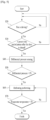
- FIG. 6 shows a step S10 of determining whether a sensing period using the differential pressure sensor 100 is satisfied before the step a step S20 of determining whether the fan is driving.
- the sensing period means a time period in which the differential pressure is measured by using the differential pressure sensor 100.
- the sensing period may be set as 20 seconds or set as variable time periods according to various conditions.
- the differential pressure sensor 100 when the pressure difference is measured by using the differential pressure sensor 100, the differential pressure sensor 100 senses the pressure difference in the sensing period, in other words, at preset time intervals. Accordingly, the electric power consumed by the differential pressure sensor 100 may be reduced.
- the differential pressure sensor 100 continuously measures pressure differences without the sensing period, it takes more electric power in transmitting the information measured by the differential pressure sensor 100 to the control unit 96 rather than the electric power consumed by the differential pressure sensor 100.
- the differential pressure sensor 100 may measure the pressure differences in the sensing periods to improve the energy efficiency of the refrigerator.
- this embodiment illustrates that the evaporator independently includes two evaporators configured of one refrigerator evaporator and the other freezer evaporator.
- the point of time when the defrosting for the freezer evaporator is performed may be the same with the point of time when the defrosting for the refrigerator evaporator.
- the points may be irrelevant.
- the defrosting is performed for the freezer evaporator, the defrosting is performed for the refrigerator evaporator at the same time.
- the defrosting may be performed for the refrigerator evaporator without regard to the start point of the defrosting for the freezer evaporator.
- the condition in which the defrosting for the freezer evaporator starts may be the point of time when a specific time, for example, the actuation time of the freezer compartment is reduced from 43 hours to 7 hours.
- the maximum 43 hours is the reference time period. In a state where the freezer door is open for 1 second, 7 minutes is reduced.
- the actuation time reaches 7 hours, the defrosting for the freezer evaporator may be performed.
- the defrosting for the refrigerator evaporator may be performed together with the defrosting for the freezer evaporator, when the condition for starting the defrosting for the refrigerator evaporator is satisfied.
- the defrosting for the refrigerator evaporator may be performed to belong to the defrosting for the freezer evaporator.
- the defrosting for the refrigerator evaporator may be performed together.
- the defrosting for the refrigerator evaporator may be independently performed without regard to the defrosting for the freezer evaporator.
- the defrosting for the freezer evaporator is performed.
- the defrosting for the refrigerator evaporator may be performed.
- the defrosting for the freezer evaporator and the defrosting for refrigerator evaporator are independently only to perform the defrosting for the evaporators. In this instance, unless the condition for defrosting the freezer evaporator is satisfied even though the heater is driven to defrost the freezer evaporator, the defrosting for the refrigerator evaporator may not be performed.
- the condition for starting the defrosting for the freezer evaporator and the condition for starting the defrosting for the refrigerator evaporator may be configured independently.
- the point of time when the defrosting for the freezer evaporator is performed may set equal to the point of time when the defrosting for the refrigerator evaporator is performed.
- the point of time when the defrosting for the refrigerator evaporator is performed may be set equal to the point of time when the defrosting for the freezer evaporator is performed.
- a degree of the ice-formation on the evaporator is sensed.
- the defrosting logic is optimized and the power consumption may be improved.
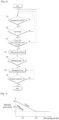
- the defrosting start condition shown in FIG. 7 may be set in consideration of the driving time of the compressor 60 to chill the storage compartments and the open time of the door 4.
- the defrosting start condition may be set in other methods and the defrosting start condition may be determined by using the differential pressure sensor 100.
- the differential pressure sensor 100 senses the pressure difference.
- the control unit 96 it is determined whether the measured pressure difference is a specific pressure value or more S120.
- the specific pressure may be variable by the user or worker diversely.
- a first defrosting is performed S130.
- the heater 50 may be driven to melt the ice formed on the evaporator 20.
- control unit 96 may heat the evaporator to have a preset temperature by using the heater 50.
- the first preset temperature may be approximately 5°C.
- control unit96 may drive the heater 50 until the temperature of the evaporator 20 rises to the first preset temperature, when the pressure difference measured by the differential pressure sensor 100 is the specific pressure or more.
- the heater 50 may be continuously driven until the step S130 finishes, in other words, until the temperature measured by the evaporator temperature sensor 92 rises to the first preset temperature.
- the control unit 95 may keep an ON-state of the heater 50 without switching off the heater 50 until the temperature measured by the evaporator temperature sensor 92 rises to the first preset temperature and the ice formed on the evaporator 20 may be eliminated.
- the heater 50 may be driven to melt the ice formed on the evaporator 20.
- the amount of the ice formed on the evaporator 20 is expected by the differential pressure sensor 100.
- the evaporator 20 is heated to a relatively high temperature.
- the evaporator 20 may be heated to a relatively low temperature.
- the heater 50 is intermittently driven while being switched into on and off.
- the heater 50 is repeatedly switched on and off to save the energy consumed by the heater 50.
- the first normal operation step means a process of chilling the storage compartments.
- the first normal operation step may mean that the storage compartments are primarily chilled to a preset temperature after the first defrosting is completed.
- the preset temperature may mean the temperature set by the user or the temperature which is somewhat different from the temperature of the storage compartment.
- the compressor 60 may be driven at a relatively high driving rpm to generate a stronger cooling power and cool the evaporator 20 rapidly.
- the second normal operation step means a process of chilling the storage compartments.
- the second normal operation step may mean that the storage compartments are primarily cooled to a preset temperature after the second defrosting.
- the preset temperature may mean the temperature of the storage compartments set by the user or the temperature which is a little different from the storage compartment temperature.
- the heater 50 supplies less heat in the second defrosting to finish the defrosting. Also, as the temperature of the evaporator 20 is relatively low in the second defrosting, the temperature of the storage compartments is not likely to rise in comparison with the first defrosting.
- the compressor 60 generates a relatively low cooling power and the energy efficiency may be enhanced.
- the control unit 96 drives the compressor 60 at a relatively low driving rpm and cools the evaporator 20 slowly.
- the evaporator temperature sensor 92 measures the temperature of the evaporator 20 and it is determined whether the measured temperature reaches a first temperature S220.
- the second defrosting step S270 and S280 may not be performed but the operation step is performed.
- the operation step is performed after the second defrosting step S270 and S280 is performed.
- the fan 40 is driven to supply the air heat-exchanged in the evaporator 20 to the storage compartments.
- the refrigerant compressed by the compressor 60 is re-supplied to the evaporator 20 and the air is cooled while exchanging heat with the evaporator 20.
- the cooled air is guided towards the storage compartments by the fan 40.
- the second temperature of the second defrosting step performed in S270 may be equal to the first temperature of the first defrosting step performed in S210.
- the temperature of the evaporator 20 is lowered while exchanging heat with the air drawn from the storage compartments.
- the heater 50 may be controlled to heat the evaporator 20 until the temperature of the evaporator 20 reaches the second temperature that is equal to the first temperature.
- the second temperature of the second defrosting step performed in S270 may be higher than the first temperature of the first defrosting step performed in S210.
- the heater 50 supplies more heat to the evaporator 20 to provide an environment where the residual ice is eliminated from the evaporator 20.
- the ice not eliminated in the first defrosting step may be eliminated. Accordingly, the reliability on the evaporator 20 may be enhanced.
- the evaporator 20 may be exposed to the higher temperature than in the first defrosting step. Moreover, the evaporator is provided with the time for melting the ice during the first defrosting step and during the second defrosting step. Accordingly, the entire time for melting the ice may be increased.
- the ice formed on the evaporator 20 may be secondarily eliminated in the second defrosting step and the reliability of the defrosting may be enhanced.
- S250 may be performed after the step of driving the fan 40 is performed for a specific time period.
- air flow is unstable in the case 35 and a high noise value could be measured by the differential pressure sensor 100. Accordingly, it is preferred that the amount of the residual ice in the evaporator 20 is sensed by using the pressure difference value measured by the differential pressure sensor 100 after the fan 40 is driven for a specific time period, for example, approximately 5 seconds.
- the driving of the fan 40 starts in a preset time period, for example, in a pause period of approximately 1 minute after the first defrosting is completed, in other words, the heater 50 is switched off. Accordingly, the air heated by the heater 50 may be prevented from being supplied to the storage compartments, without melting the ice formed on the evaporator 20.
- the fan 40 is not driven.
Landscapes
- Engineering & Computer Science (AREA)
- Physics & Mathematics (AREA)
- Mechanical Engineering (AREA)
- Thermal Sciences (AREA)
- General Engineering & Computer Science (AREA)
- Chemical & Material Sciences (AREA)
- Combustion & Propulsion (AREA)
- Defrosting Systems (AREA)
- Cold Air Circulating Systems And Constructional Details In Refrigerators (AREA)
- Devices That Are Associated With Refrigeration Equipment (AREA)
Claims (15)
- Procédé de commande d'un réfrigérateur, comprenant :la détermination si une condition de déclenchement de dégivrage d'un évaporateur (20) est satisfaite ;une première étape de dégivrage de l'évaporateur (20), ladite première étape de dégivrage se terminant lorsque la température de l'évaporateur (20) atteint une première température (S220);une étape de détection de différentiel de pression (S250) consistant à mesurer une différence entre la pression dans un premier trou traversant (110) disposé entre un trou d'entrée (32) pour aspirer l'air d'un compartiment de stockage (6, 8) et l'évaporateur (20), et la pression dans un deuxième trou traversant (120) disposé entre un trou de sortie (38) pour évacuer l'air vers le compartiment de stockage (6, 8) et l'évaporateur (20), au moyen d'un capteur de pression différentielle (100) ; etune deuxième étape de dégivrage (S270) consistant à effectuer un dégivrage supplémentaire de l'évaporateur (20) lorsque la différence de pression mesurée est égale ou supérieure à une pression prédéfinie (S260),où la condition de déclenchement de dégivrage est définie en fonction du temps de fonctionnement d'un compresseur (60) et du temps d'ouverture d'une porte (4).
- Procédé de commande selon la revendication 1, comprenant en outre :
une étape d'activation consistant à activer le compresseur (60) prévu pour refroidir le compartiment de stockage (6, 8) si la différence de pression mesurée est égale ou inférieure à la pression prédéfinie. - Procédé de commande selon la revendication 1 ou la revendication 2, où l'étape d'activation est exécutée à l'issue de la deuxième étape de dégivrage, si la différence de pression mesurée est supérieure à la pression prédéfinie.
- Procédé de commande selon la revendication 2, où, lors de l'étape d'activation, un ventilateur (40) est activé pour refouler l'air soumis à échange de chaleur avec l'évaporateur (20) vers le compartiment de stockage (6, 8).
- Procédé de commande selon la revendication 1, où un élément chauffant (50) est activé pour chauffer l'évaporateur (20) lors de la première étape de dégivrage et de la deuxième étape de dégivrage.
- Procédé de commande selon la revendication 1, où la première température est inférieure à la deuxième température.
- Procédé de commande selon la revendication 1, où la première température est égale à la deuxième température.
- Procédé de commande selon la revendication 1, comprenant en outre :
une étape d'activation de ventilateur (S240) pour refouler l'air soumis à échange de chaleur dans l'évaporateur (20) vers le compartiment de stockage (6, 8), ladite étape d'activation de ventilateur (S240) étant intercalée entre la première étape de dégivrage et l'étape de détection de différentiel de pression (S250). - Procédé de commande selon la revendication 8, où la différence de pression est mesurée (S250) après exécution de l'étape d'activation de ventilateur (S240) pendant une période spécifique.
- Procédé de commande selon la revendication 8, où l'étape d'activation de ventilateur (S240) est exécutée pendant une période prédéfinie à l'issue de la première étape de dégivrage.
- Procédé de commande selon la revendication 1, où, lors de la première étape de dégivrage et de la deuxième étape de dégivrage (S270), le ventilateur (40) prévu pour refouler vers le compartiment de stockage (6, 8) l'air soumis à échange de chaleur dans l'évaporateur (20) n'est pas activé.
- Réfrigérateur, comprenant :une carrosserie (2) où est prévu un compartiment de stockage (6, 8) ;une porte (4) prévue pour ouvrir et fermer le compartiment de stockage (6, 8) ;un boîtier (35) où se trouve un évaporateur (20), ledit boîtier (35) présentant un trou d'entrée (32) formé pour aspirer l'air du compartiment de stockage (6, 8) et un trou de sortie (38) formé pour évacuer l'air vers le compartiment de stockage (6, 8) ;un ventilateur (40) prévu pour générer un flux d'air aspiré par l'orifice d'entrée (32) et évacué par l'orifice de sortie (38) ;un capteur de pression différentielle (100) disposé dans le boîtier (35) ; etune unité de commande (96) prévue pour déterminer s'il convient d'effectuer un dégivrage supplémentaire de l'évaporateur (20) en fonction de la différence de pression détectée par le capteur de pression différentielle (100),caractérisé en ce quel'unité de commande (96) est prévue pour déterminer une condition de déclenchement de dégivrage de l'évaporateur (20), et en ce que ladite condition de déclenchement de dégivrage est définie en fonction du temps d'activation d'un compresseur (60) et du temps d'ouverture de la porte (4).
- Réfrigérateur selon la revendication 12, comprenant en outre :
un élément de chauffage (50) prévu pour chauffer l'évaporateur (20). - Réfrigérateur selon la revendication 12, où l'unité de commande (96) mesure la différence de pression après exécution du dégivrage pour chauffer l'évaporateur (20).
- Réfrigérateur selon la revendication 12, où le capteur de pression différentielle (100) présenteun premier trou traversant (110) disposé entre l'évaporateur (20) et le trou d'entrée (32) ;un deuxième trou traversant (120) disposé entre l'évaporateur (20) et le trou de sortie (38) ; etun corps prévu pour raccorder le premier trou traversant (110) au deuxième trou traversant (120), etoù le capteur de pression différentielle (100) détecte une différence entre la pression de l'air pénétrant dans le premier trou traversant (110) et la pression de l'air pénétrant dans le deuxième trou traversant (120).
Applications Claiming Priority (2)
| Application Number | Priority Date | Filing Date | Title |
|---|---|---|---|
| KR1020180022682A KR102572457B1 (ko) | 2018-02-26 | 2018-02-26 | 냉장고 및 냉장고의 제어 방법 |
| PCT/KR2018/016458 WO2019164115A1 (fr) | 2018-02-26 | 2018-12-21 | Réfrigérateur et son procédé de commande |
Publications (3)
| Publication Number | Publication Date |
|---|---|
| EP3759408A1 EP3759408A1 (fr) | 2021-01-06 |
| EP3759408A4 EP3759408A4 (fr) | 2021-11-17 |
| EP3759408B1 true EP3759408B1 (fr) | 2024-07-10 |
Family
ID=67687134
Family Applications (1)
| Application Number | Title | Priority Date | Filing Date |
|---|---|---|---|
| EP18906773.9A Active EP3759408B1 (fr) | 2018-02-26 | 2018-12-21 | Réfrigérateur et son procédé de commande |
Country Status (4)
| Country | Link |
|---|---|
| US (1) | US11549740B2 (fr) |
| EP (1) | EP3759408B1 (fr) |
| KR (1) | KR102572457B1 (fr) |
| WO (1) | WO2019164115A1 (fr) |
Families Citing this family (3)
| Publication number | Priority date | Publication date | Assignee | Title |
|---|---|---|---|---|
| CN110822787B (zh) * | 2019-10-15 | 2021-06-11 | 海信(山东)冰箱有限公司 | 一种多系统冰箱及控制方法 |
| US20210285664A1 (en) * | 2020-03-10 | 2021-09-16 | Standex International Corporation | Environmentally controlled chamber system utilizing hydrocarbon refrigerants |
| CN115930530A (zh) * | 2022-12-05 | 2023-04-07 | 珠海格力电器股份有限公司 | 一种冰箱化霜控制方法及电路 |
Family Cites Families (23)
| Publication number | Priority date | Publication date | Assignee | Title |
|---|---|---|---|---|
| US2975611A (en) | 1959-08-31 | 1961-03-21 | Gen Electric | Control system for air conditioning units |
| US3299237A (en) | 1964-03-02 | 1967-01-17 | Robertshaw Controls Co | Defroster control or the like |
| US3309887A (en) | 1965-10-18 | 1967-03-21 | Gen Electric | Household refrigerator including defrost control means |
| US3377817A (en) * | 1966-12-27 | 1968-04-16 | Trane Co | Defrost control for heating and cooling refrigeration systems |
| SE7406316L (sv) | 1974-05-10 | 1975-11-11 | Projectus Ind Produkter Ab | Forfarande och anordning for avfrostning av forangare till vermepumpar. |
| KR950001997B1 (ko) * | 1991-08-29 | 1995-03-08 | 삼성전자주식회사 | 압축기의 과부하 제어장치 |
| KR0120536B1 (ko) * | 1992-11-11 | 1997-10-22 | 윤종용 | 냉장고의 성에제거방법 및 그 장치 |
| CA2118994A1 (fr) * | 1993-06-21 | 1994-12-22 | Claude L. Bertin | Boitier cubique isole par un polyimide pour puces de dispositifs a semiconducteur empilees |
| KR0182133B1 (ko) * | 1996-07-12 | 1999-05-01 | 삼성전자주식회사 | 냉장고의 압축기 구동 제어방법 및 압축기 구동 제어장치 |
| KR980010300A (ko) | 1996-07-24 | 1998-04-30 | 구자홍 | 냉장고의 제상주기 제어방법 및 그 장치 |
| KR0170887B1 (ko) * | 1996-09-13 | 1999-03-20 | 김광호 | 냉장고 |
| KR19990003687U (ko) * | 1997-06-30 | 1999-01-25 | 배순훈 | 냉장고의 부하변동 대응장치 |
| KR100304907B1 (ko) | 1999-02-26 | 2001-09-24 | 구자홍 | 가스온풍기의 운전 제어장치 및 그 방법 |
| KR100652775B1 (ko) | 2000-01-28 | 2006-12-01 | 주식회사 엘지이아이 | 냉장고 및 그의 제상시기 결정방법 |
| KR20050096338A (ko) * | 2004-03-30 | 2005-10-06 | 삼성전자주식회사 | 냉장고 및 그 제어방법 |
| KR100719241B1 (ko) * | 2005-08-10 | 2007-05-17 | 주식회사 대우일렉트로닉스 | 인버터 냉장고의 운전 제어방법 |
| KR101275182B1 (ko) * | 2007-05-25 | 2013-06-18 | 엘지전자 주식회사 | 냉동시스템의 제어방법 |
| WO2013082401A1 (fr) * | 2011-12-02 | 2013-06-06 | Welbilt Walk-Ins, Lp | Appareil et méthode de réfrigération |
| KR101463041B1 (ko) | 2013-06-03 | 2014-11-27 | 유한회사 이지시스템 | 진공압을 이용한 제상시스템 |
| CN108885049B (zh) | 2016-01-29 | 2021-07-06 | Lg电子株式会社 | 冰箱 |
| CN105783387B (zh) | 2016-04-29 | 2018-08-28 | 合肥美的电冰箱有限公司 | 化霜控制方法、化霜控制装置和冰箱 |
| KR102725964B1 (ko) | 2016-11-10 | 2024-11-05 | 엘지전자 주식회사 | 냉장고 및 냉장고의 제어 방법 |
| KR102723276B1 (ko) | 2016-11-10 | 2024-10-31 | 엘지전자 주식회사 | 냉장고 및 냉장고의 제어 방법 |
-
2018
- 2018-02-26 KR KR1020180022682A patent/KR102572457B1/ko active Active
- 2018-12-21 US US16/965,273 patent/US11549740B2/en active Active
- 2018-12-21 EP EP18906773.9A patent/EP3759408B1/fr active Active
- 2018-12-21 WO PCT/KR2018/016458 patent/WO2019164115A1/fr not_active Ceased
Also Published As
| Publication number | Publication date |
|---|---|
| KR20190102378A (ko) | 2019-09-04 |
| EP3759408A4 (fr) | 2021-11-17 |
| KR102572457B1 (ko) | 2023-08-30 |
| US20210071931A1 (en) | 2021-03-11 |
| US11549740B2 (en) | 2023-01-10 |
| EP3759408A1 (fr) | 2021-01-06 |
| WO2019164115A1 (fr) | 2019-08-29 |
Similar Documents
| Publication | Publication Date | Title |
|---|---|---|
| EP2354736B1 (fr) | Procédé de contrôle de réfrigérateur | |
| EP3540342B1 (fr) | Réfrigérateur et procédé de commande de réfrigérateur | |
| US11940200B2 (en) | Refrigerator and control method of refrigerator | |
| JP4367570B1 (ja) | 冷蔵庫 | |
| EP3759408B1 (fr) | Réfrigérateur et son procédé de commande | |
| KR101668302B1 (ko) | 냉장고 | |
| KR101658233B1 (ko) | 냉장고의 제상 운전 제어방법 | |
| JP4364098B2 (ja) | 冷蔵庫 | |
| JP2009014313A (ja) | 冷蔵庫 | |
| KR100708622B1 (ko) | 냉장고의 제상방법 | |
| JP2006105407A (ja) | 冷蔵庫 | |
| JP5262244B2 (ja) | 冷蔵庫 | |
| CN103958990B (zh) | 单回路式制冷器具 | |
| KR20090074292A (ko) | 냉장고 및 그 제어방법 | |
| JP2012251749A (ja) | 冷蔵庫 | |
| JP2025019673A (ja) | 冷蔵庫 | |
| CN120444842A (zh) | 蒸发器化霜控制方法、计算机存储介质以及制冷设备 | |
| JP2024138688A (ja) | 冷蔵庫 | |
| JP5262245B2 (ja) | 冷蔵庫 | |
| JP2009243776A (ja) | 冷蔵庫 |
Legal Events
| Date | Code | Title | Description |
|---|---|---|---|
| STAA | Information on the status of an ep patent application or granted ep patent |
Free format text: STATUS: THE INTERNATIONAL PUBLICATION HAS BEEN MADE |
|
| PUAI | Public reference made under article 153(3) epc to a published international application that has entered the european phase |
Free format text: ORIGINAL CODE: 0009012 |
|
| STAA | Information on the status of an ep patent application or granted ep patent |
Free format text: STATUS: REQUEST FOR EXAMINATION WAS MADE |
|
| 17P | Request for examination filed |
Effective date: 20200921 |
|
| AK | Designated contracting states |
Kind code of ref document: A1 Designated state(s): AL AT BE BG CH CY CZ DE DK EE ES FI FR GB GR HR HU IE IS IT LI LT LU LV MC MK MT NL NO PL PT RO RS SE SI SK SM TR |
|
| AX | Request for extension of the european patent |
Extension state: BA ME |
|
| DAV | Request for validation of the european patent (deleted) | ||
| DAX | Request for extension of the european patent (deleted) | ||
| REG | Reference to a national code |
Ref legal event code: R079 Ipc: F25D0021020000 Ref country code: DE Ref document number: 602018071721 Country of ref document: DE Free format text: PREVIOUS MAIN CLASS: F25D0029000000 |
|
| A4 | Supplementary search report drawn up and despatched |
Effective date: 20211020 |
|
| RIC1 | Information provided on ipc code assigned before grant |
Ipc: F25B 49/02 20060101ALI20211014BHEP Ipc: F25D 21/02 20060101AFI20211014BHEP |
|
| GRAP | Despatch of communication of intention to grant a patent |
Free format text: ORIGINAL CODE: EPIDOSNIGR1 |
|
| STAA | Information on the status of an ep patent application or granted ep patent |
Free format text: STATUS: GRANT OF PATENT IS INTENDED |
|
| INTG | Intention to grant announced |
Effective date: 20240130 |
|
| GRAS | Grant fee paid |
Free format text: ORIGINAL CODE: EPIDOSNIGR3 |
|
| GRAA | (expected) grant |
Free format text: ORIGINAL CODE: 0009210 |
|
| STAA | Information on the status of an ep patent application or granted ep patent |
Free format text: STATUS: THE PATENT HAS BEEN GRANTED |
|
| AK | Designated contracting states |
Kind code of ref document: B1 Designated state(s): AL AT BE BG CH CY CZ DE DK EE ES FI FR GB GR HR HU IE IS IT LI LT LU LV MC MK MT NL NO PL PT RO RS SE SI SK SM TR |
|
| REG | Reference to a national code |
Ref country code: CH Ref legal event code: EP |
|
| REG | Reference to a national code |
Ref country code: DE Ref legal event code: R096 Ref document number: 602018071721 Country of ref document: DE |
|
| REG | Reference to a national code |
Ref country code: LT Ref legal event code: MG9D |
|
| REG | Reference to a national code |
Ref country code: NL Ref legal event code: MP Effective date: 20240710 |
|
| PG25 | Lapsed in a contracting state [announced via postgrant information from national office to epo] |
Ref country code: PT Free format text: LAPSE BECAUSE OF FAILURE TO SUBMIT A TRANSLATION OF THE DESCRIPTION OR TO PAY THE FEE WITHIN THE PRESCRIBED TIME-LIMIT Effective date: 20241111 |
|
| REG | Reference to a national code |
Ref country code: AT Ref legal event code: MK05 Ref document number: 1702345 Country of ref document: AT Kind code of ref document: T Effective date: 20240710 |
|
| PG25 | Lapsed in a contracting state [announced via postgrant information from national office to epo] |
Ref country code: NL Free format text: LAPSE BECAUSE OF FAILURE TO SUBMIT A TRANSLATION OF THE DESCRIPTION OR TO PAY THE FEE WITHIN THE PRESCRIBED TIME-LIMIT Effective date: 20240710 |
|
| PG25 | Lapsed in a contracting state [announced via postgrant information from national office to epo] |
Ref country code: PT Free format text: LAPSE BECAUSE OF FAILURE TO SUBMIT A TRANSLATION OF THE DESCRIPTION OR TO PAY THE FEE WITHIN THE PRESCRIBED TIME-LIMIT Effective date: 20241111 Ref country code: NL Free format text: LAPSE BECAUSE OF FAILURE TO SUBMIT A TRANSLATION OF THE DESCRIPTION OR TO PAY THE FEE WITHIN THE PRESCRIBED TIME-LIMIT Effective date: 20240710 |
|
| PG25 | Lapsed in a contracting state [announced via postgrant information from national office to epo] |
Ref country code: NO Free format text: LAPSE BECAUSE OF FAILURE TO SUBMIT A TRANSLATION OF THE DESCRIPTION OR TO PAY THE FEE WITHIN THE PRESCRIBED TIME-LIMIT Effective date: 20241010 |
|
| PG25 | Lapsed in a contracting state [announced via postgrant information from national office to epo] |
Ref country code: FI Free format text: LAPSE BECAUSE OF FAILURE TO SUBMIT A TRANSLATION OF THE DESCRIPTION OR TO PAY THE FEE WITHIN THE PRESCRIBED TIME-LIMIT Effective date: 20240710 Ref country code: PL Free format text: LAPSE BECAUSE OF FAILURE TO SUBMIT A TRANSLATION OF THE DESCRIPTION OR TO PAY THE FEE WITHIN THE PRESCRIBED TIME-LIMIT Effective date: 20240710 Ref country code: GR Free format text: LAPSE BECAUSE OF FAILURE TO SUBMIT A TRANSLATION OF THE DESCRIPTION OR TO PAY THE FEE WITHIN THE PRESCRIBED TIME-LIMIT Effective date: 20241011 |
|
| PG25 | Lapsed in a contracting state [announced via postgrant information from national office to epo] |
Ref country code: BG Free format text: LAPSE BECAUSE OF FAILURE TO SUBMIT A TRANSLATION OF THE DESCRIPTION OR TO PAY THE FEE WITHIN THE PRESCRIBED TIME-LIMIT Effective date: 20240710 |
|
| PG25 | Lapsed in a contracting state [announced via postgrant information from national office to epo] |
Ref country code: LV Free format text: LAPSE BECAUSE OF FAILURE TO SUBMIT A TRANSLATION OF THE DESCRIPTION OR TO PAY THE FEE WITHIN THE PRESCRIBED TIME-LIMIT Effective date: 20240710 |
|
| PG25 | Lapsed in a contracting state [announced via postgrant information from national office to epo] |
Ref country code: IS Free format text: LAPSE BECAUSE OF FAILURE TO SUBMIT A TRANSLATION OF THE DESCRIPTION OR TO PAY THE FEE WITHIN THE PRESCRIBED TIME-LIMIT Effective date: 20241110 Ref country code: AT Free format text: LAPSE BECAUSE OF FAILURE TO SUBMIT A TRANSLATION OF THE DESCRIPTION OR TO PAY THE FEE WITHIN THE PRESCRIBED TIME-LIMIT Effective date: 20240710 |
|
| PG25 | Lapsed in a contracting state [announced via postgrant information from national office to epo] |
Ref country code: HR Free format text: LAPSE BECAUSE OF FAILURE TO SUBMIT A TRANSLATION OF THE DESCRIPTION OR TO PAY THE FEE WITHIN THE PRESCRIBED TIME-LIMIT Effective date: 20240710 |
|
| PG25 | Lapsed in a contracting state [announced via postgrant information from national office to epo] |
Ref country code: ES Free format text: LAPSE BECAUSE OF FAILURE TO SUBMIT A TRANSLATION OF THE DESCRIPTION OR TO PAY THE FEE WITHIN THE PRESCRIBED TIME-LIMIT Effective date: 20240710 Ref country code: RS Free format text: LAPSE BECAUSE OF FAILURE TO SUBMIT A TRANSLATION OF THE DESCRIPTION OR TO PAY THE FEE WITHIN THE PRESCRIBED TIME-LIMIT Effective date: 20241010 |
|
| PG25 | Lapsed in a contracting state [announced via postgrant information from national office to epo] |
Ref country code: RS Free format text: LAPSE BECAUSE OF FAILURE TO SUBMIT A TRANSLATION OF THE DESCRIPTION OR TO PAY THE FEE WITHIN THE PRESCRIBED TIME-LIMIT Effective date: 20241010 Ref country code: PL Free format text: LAPSE BECAUSE OF FAILURE TO SUBMIT A TRANSLATION OF THE DESCRIPTION OR TO PAY THE FEE WITHIN THE PRESCRIBED TIME-LIMIT Effective date: 20240710 Ref country code: NO Free format text: LAPSE BECAUSE OF FAILURE TO SUBMIT A TRANSLATION OF THE DESCRIPTION OR TO PAY THE FEE WITHIN THE PRESCRIBED TIME-LIMIT Effective date: 20241010 Ref country code: LV Free format text: LAPSE BECAUSE OF FAILURE TO SUBMIT A TRANSLATION OF THE DESCRIPTION OR TO PAY THE FEE WITHIN THE PRESCRIBED TIME-LIMIT Effective date: 20240710 Ref country code: IS Free format text: LAPSE BECAUSE OF FAILURE TO SUBMIT A TRANSLATION OF THE DESCRIPTION OR TO PAY THE FEE WITHIN THE PRESCRIBED TIME-LIMIT Effective date: 20241110 Ref country code: HR Free format text: LAPSE BECAUSE OF FAILURE TO SUBMIT A TRANSLATION OF THE DESCRIPTION OR TO PAY THE FEE WITHIN THE PRESCRIBED TIME-LIMIT Effective date: 20240710 Ref country code: GR Free format text: LAPSE BECAUSE OF FAILURE TO SUBMIT A TRANSLATION OF THE DESCRIPTION OR TO PAY THE FEE WITHIN THE PRESCRIBED TIME-LIMIT Effective date: 20241011 Ref country code: FI Free format text: LAPSE BECAUSE OF FAILURE TO SUBMIT A TRANSLATION OF THE DESCRIPTION OR TO PAY THE FEE WITHIN THE PRESCRIBED TIME-LIMIT Effective date: 20240710 Ref country code: ES Free format text: LAPSE BECAUSE OF FAILURE TO SUBMIT A TRANSLATION OF THE DESCRIPTION OR TO PAY THE FEE WITHIN THE PRESCRIBED TIME-LIMIT Effective date: 20240710 Ref country code: BG Free format text: LAPSE BECAUSE OF FAILURE TO SUBMIT A TRANSLATION OF THE DESCRIPTION OR TO PAY THE FEE WITHIN THE PRESCRIBED TIME-LIMIT Effective date: 20240710 Ref country code: AT Free format text: LAPSE BECAUSE OF FAILURE TO SUBMIT A TRANSLATION OF THE DESCRIPTION OR TO PAY THE FEE WITHIN THE PRESCRIBED TIME-LIMIT Effective date: 20240710 |
|
| REG | Reference to a national code |
Ref country code: DE Ref legal event code: R097 Ref document number: 602018071721 Country of ref document: DE |
|
| PG25 | Lapsed in a contracting state [announced via postgrant information from national office to epo] |
Ref country code: RO Free format text: LAPSE BECAUSE OF FAILURE TO SUBMIT A TRANSLATION OF THE DESCRIPTION OR TO PAY THE FEE WITHIN THE PRESCRIBED TIME-LIMIT Effective date: 20240710 Ref country code: SM Free format text: LAPSE BECAUSE OF FAILURE TO SUBMIT A TRANSLATION OF THE DESCRIPTION OR TO PAY THE FEE WITHIN THE PRESCRIBED TIME-LIMIT Effective date: 20240710 Ref country code: DK Free format text: LAPSE BECAUSE OF FAILURE TO SUBMIT A TRANSLATION OF THE DESCRIPTION OR TO PAY THE FEE WITHIN THE PRESCRIBED TIME-LIMIT Effective date: 20240710 |
|
| PG25 | Lapsed in a contracting state [announced via postgrant information from national office to epo] |
Ref country code: EE Free format text: LAPSE BECAUSE OF FAILURE TO SUBMIT A TRANSLATION OF THE DESCRIPTION OR TO PAY THE FEE WITHIN THE PRESCRIBED TIME-LIMIT Effective date: 20240710 |
|
| PG25 | Lapsed in a contracting state [announced via postgrant information from national office to epo] |
Ref country code: CZ Free format text: LAPSE BECAUSE OF FAILURE TO SUBMIT A TRANSLATION OF THE DESCRIPTION OR TO PAY THE FEE WITHIN THE PRESCRIBED TIME-LIMIT Effective date: 20240710 |
|
| PG25 | Lapsed in a contracting state [announced via postgrant information from national office to epo] |
Ref country code: SK Free format text: LAPSE BECAUSE OF FAILURE TO SUBMIT A TRANSLATION OF THE DESCRIPTION OR TO PAY THE FEE WITHIN THE PRESCRIBED TIME-LIMIT Effective date: 20240710 Ref country code: IT Free format text: LAPSE BECAUSE OF FAILURE TO SUBMIT A TRANSLATION OF THE DESCRIPTION OR TO PAY THE FEE WITHIN THE PRESCRIBED TIME-LIMIT Effective date: 20240710 |
|
| PLBE | No opposition filed within time limit |
Free format text: ORIGINAL CODE: 0009261 |
|
| STAA | Information on the status of an ep patent application or granted ep patent |
Free format text: STATUS: NO OPPOSITION FILED WITHIN TIME LIMIT |
|
| 26N | No opposition filed |
Effective date: 20250411 |
|
| PG25 | Lapsed in a contracting state [announced via postgrant information from national office to epo] |
Ref country code: MC Free format text: LAPSE BECAUSE OF FAILURE TO SUBMIT A TRANSLATION OF THE DESCRIPTION OR TO PAY THE FEE WITHIN THE PRESCRIBED TIME-LIMIT Effective date: 20240710 |
|
| REG | Reference to a national code |
Ref country code: CH Ref legal event code: PL |
|
| PG25 | Lapsed in a contracting state [announced via postgrant information from national office to epo] |
Ref country code: LU Free format text: LAPSE BECAUSE OF NON-PAYMENT OF DUE FEES Effective date: 20241221 |
|
| GBPC | Gb: european patent ceased through non-payment of renewal fee |
Effective date: 20241221 |
|
| PG25 | Lapsed in a contracting state [announced via postgrant information from national office to epo] |
Ref country code: SE Free format text: LAPSE BECAUSE OF FAILURE TO SUBMIT A TRANSLATION OF THE DESCRIPTION OR TO PAY THE FEE WITHIN THE PRESCRIBED TIME-LIMIT Effective date: 20240710 |
|
| REG | Reference to a national code |
Ref country code: BE Ref legal event code: MM Effective date: 20241231 |
|
| PG25 | Lapsed in a contracting state [announced via postgrant information from national office to epo] |
Ref country code: GB Free format text: LAPSE BECAUSE OF NON-PAYMENT OF DUE FEES Effective date: 20241221 Ref country code: BE Free format text: LAPSE BECAUSE OF NON-PAYMENT OF DUE FEES Effective date: 20241231 |
|
| PG25 | Lapsed in a contracting state [announced via postgrant information from national office to epo] |
Ref country code: FR Free format text: LAPSE BECAUSE OF NON-PAYMENT OF DUE FEES Effective date: 20241231 |
|
| PG25 | Lapsed in a contracting state [announced via postgrant information from national office to epo] |
Ref country code: CH Free format text: LAPSE BECAUSE OF NON-PAYMENT OF DUE FEES Effective date: 20241231 |
|
| PG25 | Lapsed in a contracting state [announced via postgrant information from national office to epo] |
Ref country code: IE Free format text: LAPSE BECAUSE OF NON-PAYMENT OF DUE FEES Effective date: 20241221 |
|
| PGFP | Annual fee paid to national office [announced via postgrant information from national office to epo] |
Ref country code: DE Payment date: 20251105 Year of fee payment: 8 |