EP3760094A2 - Appareil de traitement de sol à guidage manuel - Google Patents
Appareil de traitement de sol à guidage manuel Download PDFInfo
- Publication number
- EP3760094A2 EP3760094A2 EP20185144.1A EP20185144A EP3760094A2 EP 3760094 A2 EP3760094 A2 EP 3760094A2 EP 20185144 A EP20185144 A EP 20185144A EP 3760094 A2 EP3760094 A2 EP 3760094A2
- Authority
- EP
- European Patent Office
- Prior art keywords
- soil cultivation
- cultivation device
- liquid
- guide part
- bottom part
- Prior art date
- Legal status (The legal status is an assumption and is not a legal conclusion. Google has not performed a legal analysis and makes no representation as to the accuracy of the status listed.)
- Granted
Links
Images


Classifications
-
- A—HUMAN NECESSITIES
- A47—FURNITURE; DOMESTIC ARTICLES OR APPLIANCES; COFFEE MILLS; SPICE MILLS; SUCTION CLEANERS IN GENERAL
- A47L—DOMESTIC WASHING OR CLEANING; SUCTION CLEANERS IN GENERAL
- A47L11/00—Machines for cleaning floors, carpets, furniture, walls, or wall coverings
- A47L11/29—Floor-scrubbing machines characterised by means for taking-up dirty liquid
- A47L11/30—Floor-scrubbing machines characterised by means for taking-up dirty liquid by suction
- A47L11/302—Floor-scrubbing machines characterised by means for taking-up dirty liquid by suction having rotary tools
- A47L11/305—Floor-scrubbing machines characterised by means for taking-up dirty liquid by suction having rotary tools the tools being disc brushes
-
- A—HUMAN NECESSITIES
- A47—FURNITURE; DOMESTIC ARTICLES OR APPLIANCES; COFFEE MILLS; SPICE MILLS; SUCTION CLEANERS IN GENERAL
- A47L—DOMESTIC WASHING OR CLEANING; SUCTION CLEANERS IN GENERAL
- A47L11/00—Machines for cleaning floors, carpets, furniture, walls, or wall coverings
- A47L11/40—Parts or details of machines not provided for in groups A47L11/02 - A47L11/38, or not restricted to one of these groups, e.g. handles, arrangements of switches, skirts, buffers, levers
-
- A—HUMAN NECESSITIES
- A47—FURNITURE; DOMESTIC ARTICLES OR APPLIANCES; COFFEE MILLS; SPICE MILLS; SUCTION CLEANERS IN GENERAL
- A47L—DOMESTIC WASHING OR CLEANING; SUCTION CLEANERS IN GENERAL
- A47L11/00—Machines for cleaning floors, carpets, furniture, walls, or wall coverings
- A47L11/02—Floor surfacing or polishing machines
- A47L11/10—Floor surfacing or polishing machines motor-driven
- A47L11/14—Floor surfacing or polishing machines motor-driven with rotating tools
- A47L11/16—Floor surfacing or polishing machines motor-driven with rotating tools the tools being disc brushes
- A47L11/161—Floor surfacing or polishing machines motor-driven with rotating tools the tools being disc brushes with supply of cleaning agents
-
- A—HUMAN NECESSITIES
- A47—FURNITURE; DOMESTIC ARTICLES OR APPLIANCES; COFFEE MILLS; SPICE MILLS; SUCTION CLEANERS IN GENERAL
- A47L—DOMESTIC WASHING OR CLEANING; SUCTION CLEANERS IN GENERAL
- A47L11/00—Machines for cleaning floors, carpets, furniture, walls, or wall coverings
- A47L11/40—Parts or details of machines not provided for in groups A47L11/02 - A47L11/38, or not restricted to one of these groups, e.g. handles, arrangements of switches, skirts, buffers, levers
- A47L11/4002—Installations of electric equipment
- A47L11/4005—Arrangements of batteries or cells; Electric power supply arrangements
-
- A—HUMAN NECESSITIES
- A47—FURNITURE; DOMESTIC ARTICLES OR APPLIANCES; COFFEE MILLS; SPICE MILLS; SUCTION CLEANERS IN GENERAL
- A47L—DOMESTIC WASHING OR CLEANING; SUCTION CLEANERS IN GENERAL
- A47L11/00—Machines for cleaning floors, carpets, furniture, walls, or wall coverings
- A47L11/40—Parts or details of machines not provided for in groups A47L11/02 - A47L11/38, or not restricted to one of these groups, e.g. handles, arrangements of switches, skirts, buffers, levers
- A47L11/4013—Contaminants collecting devices, i.e. hoppers, tanks or the like
- A47L11/4016—Contaminants collecting devices, i.e. hoppers, tanks or the like specially adapted for collecting fluids
- A47L11/4022—Contaminants collecting devices, i.e. hoppers, tanks or the like specially adapted for collecting fluids with means for recycling the dirty liquid
-
- A—HUMAN NECESSITIES
- A47—FURNITURE; DOMESTIC ARTICLES OR APPLIANCES; COFFEE MILLS; SPICE MILLS; SUCTION CLEANERS IN GENERAL
- A47L—DOMESTIC WASHING OR CLEANING; SUCTION CLEANERS IN GENERAL
- A47L11/00—Machines for cleaning floors, carpets, furniture, walls, or wall coverings
- A47L11/40—Parts or details of machines not provided for in groups A47L11/02 - A47L11/38, or not restricted to one of these groups, e.g. handles, arrangements of switches, skirts, buffers, levers
- A47L11/4036—Parts or details of the surface treating tools
- A47L11/4044—Vacuuming or pick-up tools; Squeegees
-
- A—HUMAN NECESSITIES
- A47—FURNITURE; DOMESTIC ARTICLES OR APPLIANCES; COFFEE MILLS; SPICE MILLS; SUCTION CLEANERS IN GENERAL
- A47L—DOMESTIC WASHING OR CLEANING; SUCTION CLEANERS IN GENERAL
- A47L11/00—Machines for cleaning floors, carpets, furniture, walls, or wall coverings
- A47L11/40—Parts or details of machines not provided for in groups A47L11/02 - A47L11/38, or not restricted to one of these groups, e.g. handles, arrangements of switches, skirts, buffers, levers
- A47L11/4052—Movement of the tools or the like perpendicular to the cleaning surface
-
- A—HUMAN NECESSITIES
- A47—FURNITURE; DOMESTIC ARTICLES OR APPLIANCES; COFFEE MILLS; SPICE MILLS; SUCTION CLEANERS IN GENERAL
- A47L—DOMESTIC WASHING OR CLEANING; SUCTION CLEANERS IN GENERAL
- A47L11/00—Machines for cleaning floors, carpets, furniture, walls, or wall coverings
- A47L11/40—Parts or details of machines not provided for in groups A47L11/02 - A47L11/38, or not restricted to one of these groups, e.g. handles, arrangements of switches, skirts, buffers, levers
- A47L11/4061—Steering means; Means for avoiding obstacles; Details related to the place where the driver is accommodated
-
- A—HUMAN NECESSITIES
- A47—FURNITURE; DOMESTIC ARTICLES OR APPLIANCES; COFFEE MILLS; SPICE MILLS; SUCTION CLEANERS IN GENERAL
- A47L—DOMESTIC WASHING OR CLEANING; SUCTION CLEANERS IN GENERAL
- A47L11/00—Machines for cleaning floors, carpets, furniture, walls, or wall coverings
- A47L11/40—Parts or details of machines not provided for in groups A47L11/02 - A47L11/38, or not restricted to one of these groups, e.g. handles, arrangements of switches, skirts, buffers, levers
- A47L11/4075—Handles; levers
-
- A—HUMAN NECESSITIES
- A47—FURNITURE; DOMESTIC ARTICLES OR APPLIANCES; COFFEE MILLS; SPICE MILLS; SUCTION CLEANERS IN GENERAL
- A47L—DOMESTIC WASHING OR CLEANING; SUCTION CLEANERS IN GENERAL
- A47L11/00—Machines for cleaning floors, carpets, furniture, walls, or wall coverings
- A47L11/40—Parts or details of machines not provided for in groups A47L11/02 - A47L11/38, or not restricted to one of these groups, e.g. handles, arrangements of switches, skirts, buffers, levers
- A47L11/4077—Skirts or splash guards
-
- A—HUMAN NECESSITIES
- A47—FURNITURE; DOMESTIC ARTICLES OR APPLIANCES; COFFEE MILLS; SPICE MILLS; SUCTION CLEANERS IN GENERAL
- A47L—DOMESTIC WASHING OR CLEANING; SUCTION CLEANERS IN GENERAL
- A47L11/00—Machines for cleaning floors, carpets, furniture, walls, or wall coverings
- A47L11/40—Parts or details of machines not provided for in groups A47L11/02 - A47L11/38, or not restricted to one of these groups, e.g. handles, arrangements of switches, skirts, buffers, levers
- A47L11/408—Means for supplying cleaning or surface treating agents
- A47L11/4083—Liquid supply reservoirs; Preparation of the agents, e.g. mixing devices
-
- A—HUMAN NECESSITIES
- A47—FURNITURE; DOMESTIC ARTICLES OR APPLIANCES; COFFEE MILLS; SPICE MILLS; SUCTION CLEANERS IN GENERAL
- A47L—DOMESTIC WASHING OR CLEANING; SUCTION CLEANERS IN GENERAL
- A47L11/00—Machines for cleaning floors, carpets, furniture, walls, or wall coverings
- A47L11/40—Parts or details of machines not provided for in groups A47L11/02 - A47L11/38, or not restricted to one of these groups, e.g. handles, arrangements of switches, skirts, buffers, levers
- A47L11/408—Means for supplying cleaning or surface treating agents
- A47L11/4088—Supply pumps; Spraying devices; Supply conduits
-
- B—PERFORMING OPERATIONS; TRANSPORTING
- B24—GRINDING; POLISHING
- B24B—MACHINES, DEVICES, OR PROCESSES FOR GRINDING OR POLISHING; DRESSING OR CONDITIONING OF ABRADING SURFACES; FEEDING OF GRINDING, POLISHING, OR LAPPING AGENTS
- B24B55/00—Safety devices for grinding or polishing machines; Accessories fitted to grinding or polishing machines for keeping tools or parts of the machine in good working condition
- B24B55/12—Devices for exhausting mist of oil or coolant; Devices for collecting or recovering materials resulting from grinding or polishing, e.g. of precious metals, precious stones, diamonds or the like
-
- B—PERFORMING OPERATIONS; TRANSPORTING
- B24—GRINDING; POLISHING
- B24B—MACHINES, DEVICES, OR PROCESSES FOR GRINDING OR POLISHING; DRESSING OR CONDITIONING OF ABRADING SURFACES; FEEDING OF GRINDING, POLISHING, OR LAPPING AGENTS
- B24B7/00—Machines or devices designed for grinding plane surfaces on work, including polishing plane glass surfaces; Accessories therefor
- B24B7/10—Single-purpose machines or devices
- B24B7/18—Single-purpose machines or devices for grinding floorings, walls, ceilings or the like
Definitions
- the invention relates to a hand-held soil cultivation device for cultivating soils by scrubbing, polishing or grinding.
- a device for treating surfaces is known, in particular for cleaning and polishing, which provides a joint that is movable in at least two directions between a holding device and the base part.
- This joint enables the user to adjust the grip height to the user's personal size by tilting the holding device and to move the device back and forth in the processing direction, as well as to perform lateral movements with the device.
- the joint is arranged laterally on the bottom part and the bottom part has protruding parts, the lateral mobility is limited.
- a steam scrubbing machine is known with a handle part which is movable in the machining direction with respect to the base part and which has a water tank, a water pump, a heater and a steam distributor on the base part.
- a vacuum cleaner unit which is likewise attached to the bottom part and comprises a suction space, a suction pump, a suction channel and a suction opening is disclosed for dry cleaning.
- Back vacuum cleaners with a back unit and a support frame are also known, in which the back unit comprises at least one suction pump and one suction space.
- the back unit comprises at least one suction pump and one suction space.
- an energy store for supplying energy to the pump can also be provided in the back unit.
- the DE 196 22 856 A1 discloses a hand-operated surface scrubbing device which has at least one, preferably two plate brushes, and at least one roller brush, and which is moved supported on wheels. Furthermore, a suction strip is provided, which is preferably attached to the rear end of the cleaning device and which is connected to a receptacle for dirty water via a hose. A container for cleaning fluid is also attached to the surface scrubber.
- This surface scrubbing device however, has the disadvantage that its weight is increased by the liquid containers attached to the device itself, and that the wheels allow easy movement in a linear direction, but do not allow any real mobility in the lateral direction.
- a lip for a mopping device which has projections on its one side surface along its length with non-protruding spaces between the projections extending upwards from the lower edge, the other side surface being smooth. If this lip is moved with its smooth side over a floor, it forms a seal with the floor that does not let water through. If the lip with the side surface having projections is moved over the floor, water can flow through the aforementioned spaces. As a result, a suction unit consisting of two corresponding lips can take up water in two directions, back and forth.
- the invention is based on the object of providing a soil cultivation device which, in addition to polishing or grinding, also enables wet cleaning and can be easily moved and operated by hand.
- the inventive hand-held soil cultivation device has a base part with at least one tool for soil cultivation and a motor for driving the at least one tool, as well as a guide part with a handle part, the guide part via a first joint adjustable in the processing direction with a joint axis transverse to the processing direction with the Bottom part is connected.
- the bottom part has a liquid supply and a liquid intake.
- a structurally separate suction unit is provided, which comprises at least one suction turbine for taking up liquid.
- the suction unit as a separate, structurally separate unit makes it possible to keep the weight of the bottom part and the guide part low and thus to ensure that the bottom part can be moved as easily and without resistance as possible by means of the guide part.
- the structurally separate suction unit comprises at least the suction turbine.
- a container for the absorbed liquid is advantageously arranged on the base part and / or on the guide part and connected to the structurally separate suction unit via a hose.
- the structural separation of the container for the absorbed liquid from the suction turbine makes it possible to ensure in a simple manner that the suction turbine does not come into contact with liquid.
- Providing the container for the absorbed liquid on the bottom part has the further advantage that the path for the water to be absorbed from the floor into the container for the absorbed liquid is as short as possible, which increases the effective suction power of the suction turbine.
- the container for the absorbed liquid is elongated along the guide part.
- the liquid always remains in the container for the absorbed liquid, even if the guide part is inclined close to the guide part, as a result of which the movement of the bottom part by means of the guide part is not unnecessarily made difficult by the weight of the liquid.
- the structurally separate suction unit advantageously has a container for the absorbed liquid.
- the bottom part and the guide part are not weighed down by the weight of the absorbed liquid and their mobility is not restricted as a result.
- the container for the absorbed liquid advantageously has an outlet opening and an outlet connection connecting to the outlet opening or an outlet hose with a closure.
- the closure should be designed as simply as possible so that the contamination contained in the absorbed liquid does not impair the sealing ability of the closure. Furthermore, a large cover can be provided, which enables the container for the absorbed liquid to be emptied quickly and easily and also to be cleaned easily.
- the suction unit is advantageously designed as a further base unit.
- Another floor unit which for example has wheels and can be pulled behind the floor cultivation device by means of a traction device, can be implemented easily and inexpensively, since the size of a floor unit is not very critical.
- a floor unit does not have to be particularly small in order to be easy to pull on wheels and in order not to interfere with the work of the user.
- the suction unit is advantageously designed as a unit to be fastened to the body of a user.
- a unit to be attached to the body restricts the user only slightly in his freedom of movement and enables easy mobility of the base part by means of the guide part due to the lower weight of the base part and the guide part.
- the unit to be fastened to the body it is advisable to design it as a back unit or to provide a unit to be fastened around the hips or in front of the stomach.
- the unit to be fastened to the body is advantageously provided with a support frame.
- the unit to be fastened to the body can be carried comfortably by the user on the body.
- the support frame can for example be designed like the frame of a rucksack, so that the unit to be attached to the body can be comfortably carried on the back.
- the outlet opening of the container for the absorbed liquid, which is arranged on the unit to be fastened to the body, is advantageously arranged in the bottom area, wherein the outlet nozzle or the outlet tube with the closure is arranged so that it is possible for the user, while wearing the unit to be fastened to the body, to drain off the absorbed liquid.
- Discharging the absorbed liquid while the user is still wearing the unit to be attached to the body on the body has the advantage that the unit to be attached to the body does not have to be removed with the additional weight of the absorbed water, which could be cumbersome.
- the unit which is designed as a back unit and is to be fastened to the body, does not have to be removed with additional weight, since the water absorbed as additional weight can simply be drained off again beforehand.
- the bottom part is advantageously supported exclusively on the tool for soil cultivation.
- An additional support device can be dispensed with due to the low weight of the base part and the guide part.
- the soil cultivation device advantageously has at least one energy store and / or a power cable to an external energy supply for supplying the at least one tool for soil cultivation and / or the suction turbine.
- An external energy supply for the soil cultivation device connected by means of a power cable has the advantage that the soil cultivation device can be operated without an energy storage device attached to the bottom part or the guide part, which makes it possible to keep the weight of the bottom part and the guide part very low, whereby the bottom part is very manoeuvrable and easily movable by means of the guide part.
- the connection to an external power supply enables an unlimited operating time of the tillage implement.
- An energy storage device makes it possible to operate the soil cultivation device without a connection to an external energy supply and thereby increases the range of motion of the soil cultivation device. This enables, for example, the cleaning of stairwells by means of the soil cultivation device according to the invention.
- an energy store can be provided on the soil cultivation device or a power cable for connection to an external energy supply.
- At least one energy store is advantageously attached in a removable manner.
- At least one energy store is advantageously attached to the base part and / or to the guide part.
- the energy storage device can be attached to the base part and / or to the guide part in order to ensure that the base part can be moved as easily as possible by means of the guide part.
- At least one energy store is advantageously provided on the structurally separate suction unit and / or the structurally separate suction unit is connected to the base part, the guide part or the handle part via a power and / or control cable.
- An energy supply accommodated in the suction unit which supplies both the suction turbine and the at least one tool for soil cultivation, has the advantage that its weight does not restrict the movability of the base part by means of the guide part.
- the energy supply for the suction turbine is arranged on the suction unit and the energy supply for the at least one tool is attached to the base part or the guide part, no power cable needs to be provided between the suction unit and the base part, guide part or handle part.
- the base part advantageously has a loosely suspended splash guard ring which is movable in height relative to the base part and at least in sections surrounds the tool for soil cultivation.
- a splash guard ring that extends as far as possible or all the way around the tool for soil cultivation is advantageous. Because the splash guard is loosely suspended and variable in height with respect to the bottom part, it is ensured that the splash guard ring always rests flat on the working surface regardless of the movements of the bottom part and thus avoids splashing water.
- a liquid tank is advantageously provided for the liquid supply.
- the advantage is that no external water supply has to be connected, and a corresponding hose would restrict the range of motion of the soil cultivation implement.
- the liquid tank is advantageously attached to the guide part.
- the container for the absorbed liquid is also arranged on the guide part and / or on the bottom part, the total weight of the bottom part and the guide part remains largely constant, whereby a constant pressure on the tools carrying the bottom part can be ensured. This enables a constant quality of cleaning by the tools for tillage.
- the liquid tank attached to the guide part is elongated along the guide part.
- the container for the absorbed liquid is also attached in an elongated manner along the guide part, it may be possible to shape these two liquid containers identically, which enables more cost-effective production.
- the liquid tank is advantageously accommodated in the structurally separate suction unit.
- the guide part has a lower weight, which enables the user to move the base part with less effort by means of the guide part.
- the tool for soil cultivation advantageously consists of at least two counter-rotating and essentially horizontally rotating drive plates with processing attachments or of at least two counter-rotating rollers with bristles.
- the processing attachments can advantageously be brushes, plates for pads or grinding disks.
- the liquid is advantageously supplied in an area under the base part within the splash guard and / or centrally through the drive plate, which enables the liquid to be distributed as uniformly as possible.
- the liquid receptacle has a suction bar with two sealing lips, which extends at least over half the width, preferably over the entire width of the bottom part and bent around the brush, transversely to the processing direction and, viewed in the direction of movement, is arranged behind the tool for soil cultivation, wherein preferably the front sealing lip in the direction of movement is corrugated or has openings.
- the suction bar with the two sealing lips enables the liquid to be picked up directly.
- the corrugation or the openings of the front sealing lip enable the liquid to reach the area between the sealing lips and there, by means of the negative pressure generated by the suction unit, is sucked into the container for the liquid that has been taken up.
- the suction strip with the two sealing lips of the liquid receptacle is loosely attached and can be moved vertically relative to the base part.
- the height of the suction bar with the sealing lips is freely variable regardless of the vertical movements of the base part, it can be ensured that the sealing lips always sit on the working surface, so that efficient liquid absorption is made possible.
- the splash guard is arranged correspondingly loosely and independently of the vertical movements of the bottom part, it is possible, for example, to attach the squeegee with the sealing lips to the splash guard.
- the guide part at the lower end below the center but above the base part has a further joint with a further joint axis running transversely to the first joint axis, around which the guide part can be adjusted transversely to the machining direction so that the floor part is parallel to the machining surface from a user can be rotated about a vertical axis of the bottom part by at least ⁇ 45 °.
- This further joint forms a universal joint with the first joint and enables the user to rotate the base part within the working plane, even if the guide part is about the first joint axis relative to the vertical axis of the base part is inclined. This makes it easier to work on corners or niches, for example.
- the bottom part can advantageously be rotated by the user parallel to the processing surface around the vertical axis of the bottom part by at least ⁇ 270 °.
- the user can rotate the working direction of the soil working device from the standing position by 270 °, even if the guide part is inclined about the first hinge axis to the vertical axis of the base part.
- This enables the user to first operate the soil cultivation device in a direction pointing away from the user, then to rotate the bottom part by 180 ° and to move the soil cultivation device back in a direction pointing towards the user.
- the user can turn the bottom part even further while he is moving it towards himself again, so he still has full mobility in the lateral direction even when the bottom part is moved towards the user.
- This mobility enables corners, niches or protrusions to be cleaned, for example under stairs or tables.
- the mobility enables cleaning both in the forward and backward direction, as well as in the lateral direction, whereby the soil cultivation device can always be moved in the cultivation direction, which is a prerequisite for regular absorption of the liquid.
- the liquid tank for the liquid supply and / or the container for the absorbed liquid is advantageously attached around the guide part above the further joint.
- the liquid supply, the at least one tool for soil cultivation and the suction unit of the soil cultivation device can advantageously be switched separately from one another and combined as required.
- the invention relates to a hand-held soil cultivation device, which has a bottom part with at least one tool for soil cultivation and a motor for driving the at least one tool, as well as a bracket which at least partially encompasses the bottom part and transversely via a first joint that is adjustable in the processing direction and has a joint axis is connected to the processing direction with the bottom part, and has a guide part attached to the bracket with a handle part.
- the guide part has at the lower end, below the middle, but above the base part, another joint with a joint that is transverse to the first joint axis extending further joint axis, around which the guide part is adjustable transversely to the machining direction in such a way that the bottom part can be rotated by a user parallel to the machining surface about a vertical axis of the bottom part by at least ⁇ 45 °.
- the further joint forms a universal joint with the first joint and enables a user to rotate the base part within the working plane, even if the guide part is inclined about the first joint axis to the vertical axis of the base part, which enables the base part to be highly mobile.
- the machining direction of the bottom part can be pivoted parallel to the floor even when the guide part is inclined and allows corners or niches or under projections to be machined easily.
- the bottom part can advantageously be rotated by the user parallel to the processing surface around the vertical axis of the bottom part by at least ⁇ 270 °.
- the mobility enables cleaning both in the forward and backward direction, as well as in the lateral direction, even if the guide part is inclined about the first joint axis to the vertical axis of the base part, whereby the soil cultivation device can always be moved in the processing direction, which is a prerequisite for represents a regular intake of the liquid.
- the bottom part is advantageously supported exclusively on the tool for soil cultivation. As a result, the mobility of the base part is not restricted by a support device.
- the tool for soil cultivation advantageously consists of at least two counter-rotating and essentially horizontally rotating drive plates with processing attachments or of at least two counter-rotating rollers with bristles.
- the counter-rotation of two drive plates attached symmetrically around the center of the soil cultivation device leads to an even number of drive plates in a force-neutral state of the bottom part and enables a light, resistance-free state
- the base part can be guided over the floor by means of the guide part. The same applies to rollers.
- the processing attachments can advantageously be brushes, plates for pads or grinding disks.
- the tillage device can be used for a wide variety of jobs such as polishing, scrubbing or grinding.
- the soil cultivation device advantageously has at least one energy store and / or a power cable to an external energy supply to supply the tool.
- the soil cultivation device By connecting the soil cultivation device to an external energy supply by means of a power cable, an unlimited operating time is possible. Furthermore, the weight of the base part can thereby be kept low, which enables the user to easily move and guide the base part by means of the guide part.
- An energy store attached to the soil cultivation device makes it possible to dispense with the power cable to an external energy supply, which enables a greater radius of movement of the soil cultivation device. This makes it possible, for example, to use the tillage device for cleaning stairwells.
- the at least one energy store is advantageously attached to the base part and / or to the guide part.
- the at least one energy store is advantageously attached in a removable manner.
- the energy storage device can be changed and a longer operating time is made possible. Furthermore, it is possible to remove the energy store and thus to reduce the weight of the base part and / or the guide part when the soil cultivation device is connected to an external power supply, for example, so that the base part can be moved and guided more easily by means of the guide part.
- the bottom part advantageously has a loosely suspended splash guard which is movable in height relative to the bottom part and which surrounds the tool for soil cultivation at least in sections.
- the splash guard Due to the loose, vertically movable arrangement of the splash guard, it can always sit flat on the processing surface regardless of the movements of the bottom part and thus avoid splashing water.
- the base part advantageously has a liquid feed. This means that the soil cultivation device can also be used for wet scrubbing.
- the liquid is advantageously supplied in an area below the bottom part within the splash guard and / or in the center through the drive plate and the Processing attachments through. This ensures an even, areal distribution of the liquid.
- a liquid tank is advantageously provided for the liquid supply.
- the soil cultivation device does not have to be connected to an external water supply, which would restrict the range of motion of the soil cultivation device.
- the liquid tank is advantageously attached to the base part or to the guide part above the further joint. As a result, the mobility of the bottom part is restricted as little as possible by means of the guide part.
- the liquid tank attached to the guide part is elongated along the guide part.
- the liquid is as close as possible to the guide part, so that the weight of the liquid makes it as difficult as possible to move the guide part.
- the soil cultivation device advantageously has a liquid intake and a structurally separate suction unit which contains at least one suction turbine for sucking off the liquid.
- the weight of the bottom part and the guide part can be kept low, so that the bottom part can be easily moved and guided by means of the guide part.
- a container for the absorbed liquid is advantageously arranged on the base part and / or on the guide part and connected to the structurally separate suction unit via a hose.
- the structural separation of the container for the absorbed liquid from the suction turbine makes it possible to ensure in a simple manner that the suction turbine does not come into contact with liquid.
- Providing the container for the absorbed liquid on the bottom part has the further advantage that the path for the water to be absorbed from the floor into the container for the absorbed liquid is as short as possible, which increases the effective suction power of the suction turbine.
- the container for the absorbed liquid is advantageously attached to the guide part above the further joint and is elongated along the guide part.
- the structurally separate suction unit advantageously has a container for the absorbed liquid.
- the bottom part or the guide part is not made difficult by the weight of the absorbed liquid, which enables easier maneuverability.
- the suction unit is advantageously designed as a further base unit. Since a floor unit does not have to be particularly small in order to easily pull it, for example on wheels, and in order not to particularly impair the user's work, a further floor unit, which can be pulled behind the soil cultivation device for example by means of a traction device, is simple and inexpensive actionable.
- the suction unit is advantageously designed as a unit to be fastened to the body of the user.
- a unit to be attached to the body restricts the user only slightly in his freedom of movement and at the same time enables easy mobility of the base part by means of the guide part due to the lower weight of the base part and the guide part.
- it can be designed so that it can be worn either on the back, around the hips or in front of the stomach.
- the unit to be fastened to the body is advantageously provided with a support frame.
- a support frame As a result, the weight of the suction unit can be comfortably carried on the body by the user.
- a rucksack-like carrying frame can be provided so that the suction unit can be carried on the back.
- the container for the absorbed liquid is advantageously arranged in the unit to be fastened to the body and has an outlet opening and an outlet connection connecting to the outlet opening or an outlet hose with a closure.
- the bottom part and the guide part are not made more difficult by the weight of the liquid taken up.
- the closure of the outlet connection or the outlet hose should be designed as simply as possible so that the contamination contained in the absorbed liquid does not impair the sealing ability of the closure. Furthermore, a large cover can be provided, which enables emptying and also simple cleaning of the container for the liquid that has been taken up.
- the outlet opening is advantageously arranged in the bottom area, the outlet nozzle or the outlet hose with the closure being arranged in such a way that the user is able to drain the absorbed liquid while wearing the unit to be attached to the body.
- the suction unit is designed as a unit that is to be attached to the body, then the absorbed liquid has to be drained off while the one to be attached to the body is being worn Unit on the body has the advantage that later weaning is not made more difficult by the additional weight of the fluid absorbed.
- the liquid receptacle advantageously has a suction bar with two sealing lips, which extends at least over half the width, preferably over the entire width of the bottom part and curved around the tool for soil cultivation, transversely to the processing direction and, viewed in the direction of movement, arranged behind the tool for soil cultivation is, wherein preferably the front sealing lip in the direction of movement is corrugated or has openings.
- the suction bar with the sealing lips enables the liquid to be picked up directly.
- the corrugation or the openings in the front sealing lip enable the liquid to reach the area of the suction strip between the sealing lips and be sucked off there.
- the suction strip with the sealing lips of the liquid receptacle is loosely attached and can be moved vertically relative to the base part.
- the suction bar with the sealing lips is attached independently of the vertical movements of the bottom part, it can be ensured that the sealing lips always sit on the working surface, so that efficient liquid absorption is made possible.
- the splash guard is arranged correspondingly loosely and independently of the vertical movements of the bottom part, it is possible, for example, to attach the squeegee with the sealing lips to the splash guard.
- the liquid tank is advantageously attached to the structurally separate suction unit. As a result, the weight of the bottom part and / or the guide part can be kept low, which ensures that these parts can be moved more easily.
- the liquid supply, the tools for soil cultivation and the structurally separate suction unit of the soil cultivation device can be switched separately from one another and combined as required.
- the structurally separate suction unit advantageously has an energy store and a switch for supplying the suction turbine and / or the tool and / or is connected to the base part, the guide part or the handle part via a power and control cable.
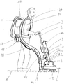
- a soil cultivation device according to the invention is shown.
- a bottom part 1 can be guided by a user P via a guide part 2 and a handle part 3, the guide part 2 being connected to the bottom part 1 via two joints which together form a universal joint.
- a first joint 4 consists of a bracket 5 and an in Fig. 3 shown, attached to the bottom part 1 axis 30, wherein a hinge axis G1, the in Fig. 3 is shown, runs along the axis 30 parallel to a machining surface B and transversely to the machining direction 6 and the bracket 5 can be moved around the axis G1 in the direction indicated by the arrow 7.
- a second joint 8 connects the guide part 2 to the bracket 5, a joint axis G2 running transversely to the joint axis G1 and the guide part being able to be moved about the axis G2 in the direction indicated by the arrow 9.
- This enables the user P to rotate the base part 1 parallel to the processing surface B about its vertical axis A1 even when the guide part 2 is inclined.
- the user P can thus rotate the machining direction 6 parallel to the machining surface B.
- the user P can, for example, first move the bottom part away from himself and then after rotating the bottom part 180 ° towards himself, the processing direction 6 accordingly first moving away from him and then towards him.
- the soil cultivation device according to the invention has a liquid tank 10 for the liquid supply, which is for example above the second joint 8 on the Guide part 2 can be attached and is connected to the bottom part 1 via a liquid feed 11.
- the liquid tank 10 it is advantageous to design the liquid tank 10 so that it extends at least partially around the guide part 2 and its dimensions are as small as possible in the direction transverse to the guide part 2, while the dimensions along the guide part 2 can be larger. As a result, the movement of the guide part 2 is made as little difficult as possible by the liquid also moving in the liquid tank 10.
- the soil cultivation device has a splash guard 12 which is arranged on the outside of the base part 1 and extends as far as possible around the base part 1.
- the splash guard 12 has bristles or lips towards the processing surface B and is arranged in such a way that its height above the processing surface B can be moved relative to the base part 1, so that its bristles or lips are always seated on the processing surface B.
- the bottom part 1 has a liquid receptacle 13 on its underside, which extends transversely to the processing direction 6 as far as possible over the width of the bottom part 1 and is arranged in the direction of movement 6 behind the bottom part 1 and attached to the splash guard 12 without the freedom of movement in height of the splash guard 12 with respect to the bottom part 1.
- the structurally separate suction unit is designed as a unit 15 to be attached to the body by a user P.
- This unit 15 to be fastened to the body is also designed as a back unit and is connected to the liquid receptacle 13 via a hose 14.
- the back unit 15 has a container 16 for the liquid taken up by the bottom surface B and a suction turbine 17 which can be driven by a motor 18 which is also arranged in the back unit 15.
- the motor 18 is connected directly to the base part 1 via a power cable and possibly also via a control cable 19, whereby a connection can be provided on the back part 15 or on the base part 1 so that this connection between the back part 15 and the base part 1 is released can.
- the power and control cable 19 can also be guided via the handle part 3 and / or the guide part to the base part 1, or a connection can be provided on the handle part 3 or on the guide part 2 to which the power and control cable 19 can be connected.
- the container 16 for the liquid absorbed by the bottom surface B can also be advantageous to arrange the container 16 for the liquid absorbed by the bottom surface B, for example, on the guide part 2 and to connect it to the liquid receptacle 13 and the suction turbine 17 via a hose each, since this enables a very short suction path, which results in the effective suction power of the Suction turbine 17 improved. It is advantageous here to shape the container 16 for the absorbed liquid elongated along the guide part 2 so that the absorbed liquid is always as close as possible to the guide part 2 and the mobility of the guide part 2 is not unnecessarily burdened by the weight of the absorbed liquid .
- both the liquid tank for the liquid supply and the container 16 for the absorbed liquid are arranged on the guide part 2 and / or on the base part 1, the total weight of the base unit consisting of base part 1 and guide part 2 remains essentially constant during soil cultivation. This makes it possible to keep the pressure on the at least one tool 31 for soil cultivation constant and thus to guarantee a constant and reliable mode of operation.
- the provision of the container 16 for the absorbed liquid on the bottom part 1 and / or on the guide part 2 has the advantage that when the hose connecting the container 16 for the absorbed liquid to the suction turbine 17 is loosened, no residual liquid remaining in the hose can run out , since the liquid remains in the lower-lying container 16 for the absorbed liquid.
- the back unit 15 has a support frame 20, as a result of which it can be carried comfortably on the back by the user P.
- support frames adapted to the type of wearing can be provided, and the shape of the unit to be fastened to the body is also to be adapted to the type of wearing.
- a back unit can, for example, have an elongated flat design and be provided with a backpack-like carrying frame. If the unit to be attached to the body is to be worn around the waist, it must be made correspondingly smaller and provided with a hip belt. For example, a unit to be fastened in front of the stomach cannot be made as long as is possible with a back unit.
- the back unit is off Fig. 1 shown in cross section.
- the container 16 for the absorbed liquid has an outlet opening 21 in the bottom area, to which an outlet hose 22 or also an outlet nozzle with a closure 23 is attached.
- the outlet hose 22 and the closure 23 are arranged in such a way that the shut-off valve 23 is operated by the user P and the absorbed liquid from the container 16 for the absorbed liquid via the drainage tube 22 can be lowered while the user P carries the back unit 15 on his back.
- a connection with a coupling can be provided for the hose 14 so that this connection of the back unit 15 to the base part 1 can be released.
- a connection piece can also be provided on the base part 1.
- the hose or socket on the bottom part can also be designed as a siphon, which prevents residual water from leaking out.
- the back unit 15 has an energy supply 24 for the motor 18 and a switch 25 for switching the suction turbine 17 on and off.
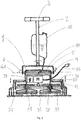
- FIG. 2 the bottom part 1 of the inventive soil cultivation device shown from below without a processing attachment.
- a motor 26 drives two drive plates 27 in opposite directions and essentially horizontally.
- the liquid receptacle 13 is attached to the splash guard 12, which in this embodiment variant extends in a ring around the entire bottom part 1, so that the free movement of the splash guard 12 is not impaired in its height above the processing surface relative to the bottom part 1.
- the liquid receptacle 13 has a suction bar 49 with two sealing lips 28, 29 spaced apart from one another in the machining direction 6, the front lip 28 in the machining direction 6 being as corrugated as possible or having openings through which, when the bottom part 1 is moved in the machining direction 6, the liquid to be absorbed into the Area x between the two sealing lips 28, 29 can get.
- This area x of the suction strip 49 between the sealing lips 28, 29 is connected via the hose 14 to the suction unit designed as a back unit 15, so that liquid can be sucked up.
- the Fig. 3 shows a cross section of the bottom part 1 with guide part 2 and handle part 3 of the soil cultivation device Fig. 1 .
- the joint 4 is shown again, which consists of the bracket 5 and the axis 30 which is fastened to the base part 1, the joint 4 being able to be moved about the joint axis G1 in the direction indicated by the arrow 7.
- the base part 1 has a tool 31 for soil cultivation, which comprises the drive plate 27 and processing attachments 32 such as brushes shown, for example, the base part 1 being supported exclusively on the tool 31.
- the processing attachments 32 arranged on the drive plates 27 are driven by the motor 26, which is supplied by an energy store 33.
- This energy store 33 is attached to the base part 1 so that it can be removed as possible and can be charged, for example, via a power cable.
- the motor 26 also has a power cable 35 if possible, which makes it possible to dispense with the energy store 33 and to connect the motor 26 to an external energy supply.
- the liquid supply 11 of the liquid from the liquid tank 10 takes place centrally through the drive plate 27.
- the splash guard 12 can be loosely connected to the base part 1 with at least one bracket 36 reaching over the base part 1, so that it is freely movable in height during processing, i.e. in the direction of the arrow 37, but when the base part 1 is lifted remains connected to the base part 1 via the at least one bracket 36.
- the user P can lift and move the base part 1 and the splash guard 12 at the same time and does not have to move the splash guard 12 additionally.
- the energy store for supplying the motor driving the suction turbine can also be arranged on the guide part, the energy store advantageously being attached below the tank 19 but above the joint 8.
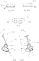
- FIG. 4 further variants of the tool 31 for soil cultivation are shown.
- the Figure 4A shows a drive plate 27 with a processing attachment 32 in the form of a plate 48 for pads 38
- FIG Figure 4B a drive plate 27 with a grinding wheel 39 is shown as a machining attachment.
- the Figure 4C shows a bottom part 1 of a soil cultivation device according to the invention, which has rollers 40 with bristles 41 on its underside as a tool 32 for soil cultivation.
- Fig. 5 A, B is shown how the bottom part 1 of the soil cultivation device according to the invention can be rotated by means of the joints 4 and 8 around the vertical axis A1 of the bottom part 1, which is essentially perpendicular to the processing surface B, with the guide part 2 inclined.
- the bottom part is also rotated by 90 ° about the vertical axis A1, with the bracket 5 moving from a starting position inclined against the first machining direction 6 to a position about the axis G1 is brought parallel to the axis A1 and the guide part 2 is moved about the further joint axis G2 from an initial alignment parallel to a longitudinal axis A3 of the bracket 5 to an alignment oblique to the longitudinal axis A3 of the bracket 5.
- the base part 1 can also be rotated by a further 90 ° by turning the handle part 3 by a further 90 °, so that the processing direction 6, which originally points away from the user P, is now directed towards the user P, according to the direction indicated by arrow 6 '.
- Fig. 6 shows a soil cultivation device according to the invention as shown in FIG Fig. 1 is shown, with the difference that the structurally separate suction unit is designed as a further base unit 42.
- the base unit 42 has a container 43 for the liquid taken up by the base area B and a suction turbine 44 which can be driven by a motor 45 which is also arranged in the base unit 42.
- the motor 42 is connected directly to the base part 1 via a power cable and possibly also via a control cable 46, with one connection can be provided on the base unit 42, on the base part 1, on the guide part 2 or on the handle part 3, so that this connection between the base unit 42 and the base part 1 can be released.
- the power and / or control cable 46 can also be guided via the handle part 3 and / or the guide part to the bottom part 1, or a connection can be provided on the handle part 3 or on the guide part 2 to which the power and / or control cable 46 can be connected.
- the base unit 42 can also have a power cable which enables the motor 45 to be connected to an external power supply.
- the base unit 42 can also have its own energy store 47 for supplying energy to the motor 45.
Landscapes
- Engineering & Computer Science (AREA)
- Mechanical Engineering (AREA)
- Life Sciences & Earth Sciences (AREA)
- Environmental & Geological Engineering (AREA)
- Sustainable Development (AREA)
- Soil Working Implements (AREA)
- Cultivation Receptacles Or Flower-Pots, Or Pots For Seedlings (AREA)
- Catching Or Destruction (AREA)
- Cleaning By Liquid Or Steam (AREA)
- Cleaning Implements For Floors, Carpets, Furniture, Walls, And The Like (AREA)
- Brushes (AREA)
- Cleaning In General (AREA)
- Processing Of Solid Wastes (AREA)
- Excavating Of Shafts Or Tunnels (AREA)
- Road Paving Machines (AREA)
- Floor Finish (AREA)
Priority Applications (1)
| Application Number | Priority Date | Filing Date | Title |
|---|---|---|---|
| EP23200915.9A EP4275571A3 (fr) | 2009-08-27 | 2010-08-25 | Appareil de traitement de sol à guidage manuel |
Applications Claiming Priority (3)
| Application Number | Priority Date | Filing Date | Title |
|---|---|---|---|
| DE102009028944A DE102009028944A1 (de) | 2009-08-27 | 2009-08-27 | Handgeführtes Bodenbearbeitungsgerät |
| EP10766222.3A EP2470055B1 (fr) | 2009-08-27 | 2010-08-25 | Appareil de traitement de sol à guidage manuel |
| PCT/DE2010/000987 WO2011023169A2 (fr) | 2009-08-27 | 2010-08-25 | Appareil de traitement de sol à guidage manuel |
Related Parent Applications (1)
| Application Number | Title | Priority Date | Filing Date |
|---|---|---|---|
| EP10766222.3A Division EP2470055B1 (fr) | 2009-08-27 | 2010-08-25 | Appareil de traitement de sol à guidage manuel |
Related Child Applications (2)
| Application Number | Title | Priority Date | Filing Date |
|---|---|---|---|
| EP23200915.9A Division-Into EP4275571A3 (fr) | 2009-08-27 | 2010-08-25 | Appareil de traitement de sol à guidage manuel |
| EP23200915.9A Division EP4275571A3 (fr) | 2009-08-27 | 2010-08-25 | Appareil de traitement de sol à guidage manuel |
Publications (4)
| Publication Number | Publication Date |
|---|---|
| EP3760094A2 true EP3760094A2 (fr) | 2021-01-06 |
| EP3760094A3 EP3760094A3 (fr) | 2021-04-21 |
| EP3760094B1 EP3760094B1 (fr) | 2023-11-08 |
| EP3760094C0 EP3760094C0 (fr) | 2023-11-08 |
Family
ID=43382445
Family Applications (7)
| Application Number | Title | Priority Date | Filing Date |
|---|---|---|---|
| EP15179868.3A Active EP2962614B1 (fr) | 2009-08-27 | 2010-08-25 | Appareil de traitement de sol à guidage manuel |
| EP23200915.9A Pending EP4275571A3 (fr) | 2009-08-27 | 2010-08-25 | Appareil de traitement de sol à guidage manuel |
| EP10766222.3A Active EP2470055B1 (fr) | 2009-08-27 | 2010-08-25 | Appareil de traitement de sol à guidage manuel |
| EP16153854.1A Active EP3033984B1 (fr) | 2009-08-27 | 2010-08-25 | Appareil de traitement de sol a guidage manuel |
| EP19209902.6A Active EP3632285B1 (fr) | 2009-08-27 | 2010-08-25 | Appareil de traitement de sol à guidage manuel |
| EP20185144.1A Active EP3760094B1 (fr) | 2009-08-27 | 2010-08-25 | Appareil de traitement de sol à guidage manuel |
| EP19155564.8A Active EP3508106B1 (fr) | 2009-08-27 | 2010-08-25 | Appareil de traitement de sol à guidage manuel |
Family Applications Before (5)
| Application Number | Title | Priority Date | Filing Date |
|---|---|---|---|
| EP15179868.3A Active EP2962614B1 (fr) | 2009-08-27 | 2010-08-25 | Appareil de traitement de sol à guidage manuel |
| EP23200915.9A Pending EP4275571A3 (fr) | 2009-08-27 | 2010-08-25 | Appareil de traitement de sol à guidage manuel |
| EP10766222.3A Active EP2470055B1 (fr) | 2009-08-27 | 2010-08-25 | Appareil de traitement de sol à guidage manuel |
| EP16153854.1A Active EP3033984B1 (fr) | 2009-08-27 | 2010-08-25 | Appareil de traitement de sol a guidage manuel |
| EP19209902.6A Active EP3632285B1 (fr) | 2009-08-27 | 2010-08-25 | Appareil de traitement de sol à guidage manuel |
Family Applications After (1)
| Application Number | Title | Priority Date | Filing Date |
|---|---|---|---|
| EP19155564.8A Active EP3508106B1 (fr) | 2009-08-27 | 2010-08-25 | Appareil de traitement de sol à guidage manuel |
Country Status (10)
| Country | Link |
|---|---|
| US (1) | US8887348B2 (fr) |
| EP (7) | EP2962614B1 (fr) |
| DE (1) | DE102009028944A1 (fr) |
| DK (5) | DK2470055T3 (fr) |
| ES (6) | ES2896239T3 (fr) |
| FI (1) | FI3632285T3 (fr) |
| HU (6) | HUE065335T2 (fr) |
| PL (6) | PL3632285T3 (fr) |
| SI (1) | SI2962614T1 (fr) |
| WO (1) | WO2011023169A2 (fr) |
Families Citing this family (34)
| Publication number | Priority date | Publication date | Assignee | Title |
|---|---|---|---|---|
| DE102009028944A1 (de) | 2009-08-27 | 2011-03-03 | Rudolf Franke | Handgeführtes Bodenbearbeitungsgerät |
| CN105143557B (zh) * | 2013-04-22 | 2018-06-12 | 胡斯华纳有限公司 | 真空连接件、真空设备及将鼓风机转换为真空设备的用途 |
| DE102013022770B4 (de) * | 2013-08-02 | 2025-11-20 | I-Mop Gmbh | Handgeführtes Bodenbearbeitungsgerät |
| DE102013215198A1 (de) | 2013-08-02 | 2015-02-05 | I-Mop Gmbh | Handgeführtes Bodenbearbeitungsgerät |
| DE102016208895A1 (de) * | 2016-05-23 | 2017-11-23 | Rudolf Franke | Bodenbearbeitungsmodul sowie Bodenbearbeitungsmaschine mit einem solchen Bodenbearbeitungsmodul |
| SE540214C2 (en) * | 2016-06-03 | 2018-05-02 | Htc Sweden Ab | Floor grinding machine, method of operating floor |
| DE102017212873A1 (de) * | 2017-07-26 | 2019-01-31 | Hawig Maschinenfabrik Gesellschaft mit beschränkter Haftung | Flächenbearbeitungsgerät |
| GB2573134B (en) * | 2018-04-25 | 2022-04-27 | Numatic Int Ltd | Floor scrubber dryer |
| DE102018207435A1 (de) * | 2018-05-14 | 2019-11-14 | Hawig Maschinenfabrik Gesellschaft mit beschränkter Haftung | Nassreinigungsvorrichtung zur Nassreinigung einer Bodenfläche |
| EP3721776B1 (fr) * | 2019-04-09 | 2024-05-29 | Hilti Aktiengesellschaft | Aspirateur humide et agencement de composants dans un tel aspirateur humide |
| CN114174014B (zh) * | 2019-07-31 | 2023-12-15 | Lg电子株式会社 | 移动机器人 |
| US11432695B2 (en) * | 2019-07-31 | 2022-09-06 | Lg Electronics Inc. | Mobile robot |
| DE102020004413A1 (de) * | 2020-07-22 | 2022-01-27 | I-Mop Gmbh | Bodenreinigungsvorrichtung, insbesondere Scheuer-Saug-Bodenreinigungsvorrichtung, mit verbesserten Manövriereigenschaften |
| NL2026276B1 (en) | 2020-08-17 | 2022-04-14 | Wensch Holding B V | Self-propelled cleaning device |
| US11771292B1 (en) | 2020-09-10 | 2023-10-03 | Karma 360, Inc. | Floor scrubber apparatus with releasably locking handle |
| US11618121B2 (en) * | 2020-09-23 | 2023-04-04 | SlurryMonster, LLC | Assembly for a floor processing machine |
| ES3038264T3 (en) | 2021-03-26 | 2025-10-10 | Dextron Tech Ltd | Surface treatment tool |
| CN117795212A (zh) | 2021-06-26 | 2024-03-29 | 坦南特公司 | 扭矩传递球接头 |
| DE102021116686B3 (de) | 2021-06-29 | 2022-08-25 | Hako Gmbh | Bodenreinigungsmaschine |
| DE102021116683B4 (de) | 2021-06-29 | 2023-03-23 | Hako Gmbh | Bodenreinigungsmaschine |
| DE212021000578U1 (de) | 2021-11-05 | 2024-05-06 | Numatic International Limited | Bodenbehandlungsmaschine |
| DE102021129923B4 (de) | 2021-11-16 | 2024-07-04 | Hako Gmbh | Handgeführte Bodenreinigungsmaschine |
| GB2615080A (en) | 2022-01-26 | 2023-08-02 | Numatic Int Ltd | Floor treatment machine |
| GB2622398B (en) | 2022-09-14 | 2025-05-14 | Numatic Int Ltd | Floor treatment machine |
| US11858698B1 (en) * | 2022-10-24 | 2024-01-02 | The Procter & Gamble Company | Coupling shell for a floor treatment composition dispensing package |
| USD1105672S1 (en) | 2023-08-30 | 2025-12-09 | Sharkninja Operating Llc | Vacuum cleaner and vacuum nozzle |
| WO2025168842A2 (fr) * | 2024-02-09 | 2025-08-14 | I-Mop Gmbh | Appareil de nettoyage de surfaces, réservoir de fluide pour un appareil de nettoyage de surfaces, système de nettoyage de surfaces et procédé de nettoyage de surfaces |
| DE102024105791A1 (de) * | 2024-02-29 | 2025-09-04 | Alfred Kärcher SE & Co. KG | Bodenreinigungsmaschine mit Gebläseeinrichtung am Bodenkopf |
| GB2640707A (en) | 2024-05-02 | 2025-11-05 | Numatic Int Ltd | Floor treatment machine |
| DE102024113192A1 (de) * | 2024-05-10 | 2025-11-13 | I-Mop Gmbh | Flächenreinigungskopf für ein Flächenreinigungsgerät |
| NL2037675B1 (en) | 2024-05-13 | 2025-11-25 | Wensch Holding B V | Scrubber-drier |
| USD1113019S1 (en) | 2024-05-31 | 2026-02-10 | Sharkninja Operating Llc | Steam cleaner |
| US20260102876A1 (en) * | 2024-07-19 | 2026-04-16 | Ceramtec Gmbh | Device for Collecting Machining Suspensions with Material Removal and/or Tool Wear Used During the Machining of Workpiece Parts |
| WO2026052955A1 (fr) | 2024-09-05 | 2026-03-12 | Numatic International Limited | Machine de traitement de sols |
Citations (9)
| Publication number | Priority date | Publication date | Assignee | Title |
|---|---|---|---|---|
| US2541812A (en) | 1947-10-30 | 1951-02-13 | Walter S Finnell | Floor processing machine |
| DE2139156A1 (de) | 1971-08-05 | 1973-02-15 | Andrae P Kg | Verteilerscheibe zum auftragen fluessiger reinigungsmittel |
| US3943591A (en) | 1973-06-14 | 1976-03-16 | Marie Marguerite Lanusse | Fluid-product projection apparatus for maintenance of various articles |
| EP0560523A2 (fr) | 1992-03-13 | 1993-09-15 | Tennant Company | Lame pour raclette |
| DE19622856A1 (de) | 1995-06-23 | 1997-01-02 | Cleanfix Reinigungssysteme Ag | Flächenschrubbgerät |
| WO1999005955A1 (fr) | 1997-07-29 | 1999-02-11 | Stig Olsson | Dispositif pour machine a nettoyer |
| EP0978249A2 (fr) | 1998-08-04 | 2000-02-09 | Kenter, Rainer | Appareil de traitement de surfaces |
| DE20302630U1 (de) | 2003-02-18 | 2003-04-30 | Hsu, Bill, Shinjuang, Taipeh | Dampfschrubbmaschine |
| WO2011023169A2 (fr) | 2009-08-27 | 2011-03-03 | Rainer Kenter | Appareil de traitement de sol à guidage manuel |
Family Cites Families (61)
| Publication number | Priority date | Publication date | Assignee | Title |
|---|---|---|---|---|
| US2923956A (en) | 1960-02-09 | bixler | ||
| GB470192A (en) | 1936-03-04 | 1937-08-11 | Frederick William Taylor | Improvements in or relating to portable machines for treating floors and articles laid thereon |
| US2495686A (en) | 1947-11-24 | 1950-01-31 | Berberian Edward | Surface cleaning and shampooing machine |
| US2635278A (en) * | 1951-08-18 | 1953-04-21 | William J Belknap | Floor drying apparatus containing baffle structure for separation of entrained liquid |
| US3013287A (en) | 1959-05-26 | 1961-12-19 | Electrolux Ab | Floor polisher |
| US3101505A (en) | 1961-07-18 | 1963-08-27 | Electrolux Corp | Surface treating machine |
| US3107387A (en) * | 1962-02-26 | 1963-10-22 | Katt Sam | Double action squeegee |
| GB1023394A (en) | 1964-04-27 | 1966-03-23 | R G Dixon And Company Ltd | Improvements in or relating to floor cleaning liquid pick-up devices |
| US3778860A (en) | 1972-07-06 | 1973-12-18 | Minnesota Mining & Mfg | Mop frame assembly |
| US4146944A (en) | 1977-08-19 | 1979-04-03 | General Signal Corporation | Carpet cleaning machine |
| JPS5654050U (fr) | 1979-10-01 | 1981-05-12 | ||
| DE8027356U1 (de) * | 1980-10-14 | 1981-03-12 | Alfred Kärcher GmbH & Co, 7057 Winnenden | Bodenreinigungskopf |
| US4339841A (en) | 1980-11-12 | 1982-07-20 | Wetrok, Inc. | Squeegee support assembly for automatic floor cleaning machines |
| US4499624A (en) * | 1983-02-25 | 1985-02-19 | The Kartridg Pak Company | Portable polisher |
| US4570278A (en) * | 1983-02-25 | 1986-02-18 | The Kartridg Pak Co. | Portable polisher and buffs therefor |
| DE3542631A1 (de) * | 1985-12-03 | 1987-06-04 | Kaercher Gmbh & Co Alfred | Reinigungsgeraet fuer hartflaechen |
| US4817233A (en) | 1988-04-22 | 1989-04-04 | Tennant Company | Scrubber squeegees for scrubbing forward and backward |
| US4937911A (en) * | 1988-06-03 | 1990-07-03 | Picchietti Sr Remo | Bowling alley lane cleaning apparatus |
| AU636137B2 (en) * | 1989-03-09 | 1993-04-22 | Bo Vilhelm Lilja | A machine for treating floor surfaces |
| JPH08256960A (ja) | 1995-01-24 | 1996-10-08 | Minolta Co Ltd | 作業装置 |
| US5735959A (en) | 1994-06-15 | 1998-04-07 | Minolta Co, Ltd. | Apparatus spreading fluid on floor while moving |
| CH690396A5 (de) | 1994-10-17 | 2000-08-31 | Thomas Robert Metall Elektro | Staubsauger. |
| US5545080A (en) * | 1995-02-16 | 1996-08-13 | Porter-Cable Corporation | Motorized sander having a sanding head mounted by a pivotal joint |
| US5596787A (en) * | 1995-08-08 | 1997-01-28 | Stevens; Elwood L. | Wiping device for interior surfaces of vehicle windshield glass |
| JP3366187B2 (ja) | 1996-05-17 | 2003-01-14 | アマノ株式会社 | 床面洗浄機用スキージ |
| US5706549A (en) | 1996-06-25 | 1998-01-13 | Advance Machine Company | Rotary disc floor cleaning apparatus |
| CN1194129A (zh) | 1996-12-31 | 1998-09-30 | 皇家用具制造公司 | 电池式湿拖把和真空装置 |
| AU2333699A (en) | 1998-01-23 | 1999-08-09 | Interface, Inc. | Combination carpet cleaning brush unit, vacuum and pile lifter |
| DE29813950U1 (de) | 1998-08-04 | 1999-01-07 | Kenter, Rainer, 89312 Günzburg | Vorrichtung zum Behandeln von Oberflächen |
| DE19838072A1 (de) * | 1998-08-21 | 2000-03-02 | Dornier Tech Gmbh & Co | Reinigungsvorrichtung für Fenster-, Dach- und Fassadenflächen |
| DE10025447A1 (de) | 2000-05-23 | 2001-11-29 | Bsh Bosch Siemens Hausgeraete | Reinigungsgerät |
| JP3781947B2 (ja) | 2000-05-25 | 2006-06-07 | アマノ株式会社 | 床面洗浄清掃機 |
| US20010049854A1 (en) | 2000-06-05 | 2001-12-13 | Dalbey Jay Scott | Portable steam cleaner with back harness |
| TW558430B (en) * | 2000-11-01 | 2003-10-21 | Kao Corp | Cleaning device |
| JP2002143064A (ja) | 2000-11-07 | 2002-05-21 | Amano Corp | 床面洗浄装置 |
| US6572711B2 (en) * | 2000-12-01 | 2003-06-03 | The Hoover Company | Multi-purpose position sensitive floor cleaning device |
| JP3871888B2 (ja) | 2001-02-14 | 2007-01-24 | アマノ株式会社 | 床面洗浄機用スキージ |
| JP3737380B2 (ja) | 2001-04-12 | 2006-01-18 | 日本原子力発電株式会社 | 原子力施設等で用いる床面除染装置 |
| KR100442940B1 (ko) | 2002-04-03 | 2004-08-04 | 정석동 | 스팀 발생기가 장착된 회전형 진공청소기 |
| GB2391459A (en) | 2002-08-09 | 2004-02-11 | Dyson Ltd | A surface treating appliance with increased manoeuverability |
| US20040034953A1 (en) | 2002-08-26 | 2004-02-26 | Huang Chu Lan | Electric mop |
| JP2004105592A (ja) | 2002-09-20 | 2004-04-08 | Seidensha:Kk | 角型たわし状ブラシを用いた床清掃装置 |
| JP2006516423A (ja) * | 2003-01-10 | 2006-07-06 | ロイヤル アプライアンス マニュファクチュアリング カンパニー | 吸入式ウェット・ジェットモップ |
| US7823250B2 (en) | 2003-08-26 | 2010-11-02 | Bissell Homecare, Inc. | Bare floor cleaner |
| CA3001182C (fr) * | 2003-09-03 | 2020-03-24 | The Procter & Gamble Company | Outil de nettoyage polyvalent |
| SE0400642D0 (sv) * | 2004-03-15 | 2004-03-15 | Electrolux Ab | Floor cleaning implement |
| US20060112513A1 (en) * | 2004-11-29 | 2006-06-01 | Tetteh Albert E | Indoor/outdoor cleaning system |
| US7811022B2 (en) | 2005-06-29 | 2010-10-12 | Electrolux Home Care Products, Inc. | Flexible floor cleaning device |
| DE102005032488A1 (de) | 2005-07-04 | 2007-01-11 | Alfred Kärcher Gmbh & Co. Kg | Fahrbares Bodenreinigungsgerät |
| JP2007054405A (ja) | 2005-08-25 | 2007-03-08 | Kao Corp | 清掃具 |
| US7770254B2 (en) * | 2005-11-21 | 2010-08-10 | Fna Ip Holdings, Inc. | Floor scrubber |
| JP2007175244A (ja) | 2005-12-27 | 2007-07-12 | Kao Corp | ブラシ体 |
| US20080040883A1 (en) * | 2006-04-10 | 2008-02-21 | Jonas Beskow | Air Flow Losses in a Vacuum Cleaners |
| ITPN20060086A1 (it) | 2006-11-03 | 2008-05-04 | Cfm Nilfisk Advance S P A | Macchina lava pavimenti |
| EP2117402B1 (fr) | 2006-12-13 | 2015-05-27 | Aktiebolaget Electrolux | Dispositif de nettoyage du sol humide/sec |
| DE102007010303A1 (de) * | 2007-02-22 | 2008-08-28 | Flex-Elektrowerkzeuge Gmbh | Handgehaltene Reinigungs-/Schleifmaschine |
| CA2695815A1 (fr) | 2007-08-06 | 2009-02-12 | Dovia International Limited | Dispositif pour eliminer des debris de surface |
| CN201094599Y (zh) | 2007-09-14 | 2008-08-06 | 上海富培贸易有限公司 | 电动扫地机 |
| KR100864697B1 (ko) * | 2007-10-30 | 2008-10-23 | 안봉주 | 물걸레 청소기 |
| KR20090071509A (ko) * | 2007-12-27 | 2009-07-01 | 이인태 | 회전형 청소기와 이를 위한 물통 |
| US8161595B1 (en) * | 2008-04-17 | 2012-04-24 | Wilson Javan E | Vacuum cleaner with scrubbers |
-
2009
- 2009-08-27 DE DE102009028944A patent/DE102009028944A1/de active Pending
-
2010
- 2010-08-25 DK DK10766222.3T patent/DK2470055T3/da active
- 2010-08-25 HU HUE20185144A patent/HUE065335T2/hu unknown
- 2010-08-25 EP EP15179868.3A patent/EP2962614B1/fr active Active
- 2010-08-25 PL PL19209902.6T patent/PL3632285T3/pl unknown
- 2010-08-25 EP EP23200915.9A patent/EP4275571A3/fr active Pending
- 2010-08-25 ES ES16153854T patent/ES2896239T3/es active Active
- 2010-08-25 EP EP10766222.3A patent/EP2470055B1/fr active Active
- 2010-08-25 HU HUE19209902A patent/HUE062174T2/hu unknown
- 2010-08-25 ES ES20185144T patent/ES2969333T3/es active Active
- 2010-08-25 EP EP16153854.1A patent/EP3033984B1/fr active Active
- 2010-08-25 SI SI201031626T patent/SI2962614T1/en unknown
- 2010-08-25 FI FIEP19209902.6T patent/FI3632285T3/fi active
- 2010-08-25 ES ES15179868.3T patent/ES2655252T3/es active Active
- 2010-08-25 EP EP19209902.6A patent/EP3632285B1/fr active Active
- 2010-08-25 ES ES19209902T patent/ES2948241T3/es active Active
- 2010-08-25 DK DK19209902.6T patent/DK3632285T3/da active
- 2010-08-25 PL PL10766222T patent/PL2470055T3/pl unknown
- 2010-08-25 PL PL20185144.1T patent/PL3760094T3/pl unknown
- 2010-08-25 HU HUE19155564A patent/HUE056481T2/hu unknown
- 2010-08-25 US US13/392,122 patent/US8887348B2/en active Active
- 2010-08-25 ES ES10766222T patent/ES2822106T3/es active Active
- 2010-08-25 HU HUE10766222A patent/HUE051131T2/hu unknown
- 2010-08-25 EP EP20185144.1A patent/EP3760094B1/fr active Active
- 2010-08-25 HU HUE16153854A patent/HUE056475T2/hu unknown
- 2010-08-25 PL PL15179868T patent/PL2962614T3/pl unknown
- 2010-08-25 DK DK15179868.3T patent/DK2962614T3/en active
- 2010-08-25 DK DK19155564.8T patent/DK3508106T3/da active
- 2010-08-25 ES ES19155564T patent/ES2897908T3/es active Active
- 2010-08-25 WO PCT/DE2010/000987 patent/WO2011023169A2/fr not_active Ceased
- 2010-08-25 DK DK16153854.1T patent/DK3033984T3/da active
- 2010-08-25 PL PL16153854T patent/PL3033984T3/pl unknown
- 2010-08-25 EP EP19155564.8A patent/EP3508106B1/fr active Active
- 2010-08-25 PL PL19155564T patent/PL3508106T3/pl unknown
- 2010-08-25 HU HUE15179868A patent/HUE035851T2/en unknown
Patent Citations (9)
| Publication number | Priority date | Publication date | Assignee | Title |
|---|---|---|---|---|
| US2541812A (en) | 1947-10-30 | 1951-02-13 | Walter S Finnell | Floor processing machine |
| DE2139156A1 (de) | 1971-08-05 | 1973-02-15 | Andrae P Kg | Verteilerscheibe zum auftragen fluessiger reinigungsmittel |
| US3943591A (en) | 1973-06-14 | 1976-03-16 | Marie Marguerite Lanusse | Fluid-product projection apparatus for maintenance of various articles |
| EP0560523A2 (fr) | 1992-03-13 | 1993-09-15 | Tennant Company | Lame pour raclette |
| DE19622856A1 (de) | 1995-06-23 | 1997-01-02 | Cleanfix Reinigungssysteme Ag | Flächenschrubbgerät |
| WO1999005955A1 (fr) | 1997-07-29 | 1999-02-11 | Stig Olsson | Dispositif pour machine a nettoyer |
| EP0978249A2 (fr) | 1998-08-04 | 2000-02-09 | Kenter, Rainer | Appareil de traitement de surfaces |
| DE20302630U1 (de) | 2003-02-18 | 2003-04-30 | Hsu, Bill, Shinjuang, Taipeh | Dampfschrubbmaschine |
| WO2011023169A2 (fr) | 2009-08-27 | 2011-03-03 | Rainer Kenter | Appareil de traitement de sol à guidage manuel |
Also Published As
Similar Documents
| Publication | Publication Date | Title |
|---|---|---|
| EP3760094B1 (fr) | Appareil de traitement de sol à guidage manuel | |
| DE69502840T2 (de) | Reinigungsvorrichtung zum Auftragen und Wiederaufsaugen von Reinigungsflüssigkeit | |
| EP3426124B1 (fr) | Nouveau dispositif de nettoyage et procédé de nettoyage | |
| DE202005022120U1 (de) | Vorrichtung zur Bodenreinigung und -behandlung | |
| DE102014114809A1 (de) | Flächen-Reinigungsmaschine mit Befeuchtungseinrichtung | |
| EP2160125A1 (fr) | Appareil de nettoyage de sol comprenant un réservoir de liquide de nettoyage et un réservoir de liquide sale | |
| DE102010038422A1 (de) | Bodenreinigungsgerät | |
| EP2773254A1 (fr) | Machine de nettoyage des sols guidée à la main | |
| DE102024103715A1 (de) | Flächenreinigungsgerät, Fluidtank für ein Flächenreinigungsgerät, Flächenreinigungssystem und Verfahren zur Flächenreinigung | |
| DE202023104662U1 (de) | Autonomer Bodenreiniger mit Scheuerriemen | |
| EP0292900B1 (fr) | Appareil d'arrosage et d'extraction | |
| DE102023136195A1 (de) | Flächenbehandlungssystem | |
| DE102023136194A1 (de) | Flächenbehandlungssystem | |
| EP4257025A2 (fr) | Appareil de traitement du sol guidé à la main, unité d'alimentation pour un appareil de traitement du sol guidé à la main, procédé de fabrication d'un appareil de traitement du sol guidé à la main et procédé de nettoyage du sol | |
| WO2025181218A1 (fr) | Machine de nettoyage de sols avec dispositif de ventilation | |
| EP3048943B1 (fr) | Suceur d'aspirateur pour appareil de nettoyage et appareil de nettoyage | |
| DE102021134552A1 (de) | Bodenreinigungsmaschine mit Schwenkgelenk und Verfahren zum Betreiben einer Bodenreinigungsmaschine | |
| DE202024002650U1 (de) | Flächenreinigungsgerät | |
| DE202006001258U1 (de) | Fahrbares Reinigungsgerät, insbesondere für landwirtschaftliche Spaltböden | |
| DE102013022770B4 (de) | Handgeführtes Bodenbearbeitungsgerät | |
| WO2025168842A2 (fr) | Appareil de nettoyage de surfaces, réservoir de fluide pour un appareil de nettoyage de surfaces, système de nettoyage de surfaces et procédé de nettoyage de surfaces | |
| DE202024106594U1 (de) | Autonomer Reinigungsroboter mit Reinigungsvorrichtung | |
| DE827437C (de) | Elektrisch betriebenes Putzgeraet fuer Pferde und Rinder | |
| EP4201283A1 (fr) | Machine de nettoyage du sol dotée d'au moins un élément de support | |
| DE1559110A1 (de) | Vorrichtung zum Entfernen von Schlamm aus Schwimmbecken od.dgl. |
Legal Events
| Date | Code | Title | Description |
|---|---|---|---|
| PUAI | Public reference made under article 153(3) epc to a published international application that has entered the european phase |
Free format text: ORIGINAL CODE: 0009012 |
|
| STAA | Information on the status of an ep patent application or granted ep patent |
Free format text: STATUS: THE APPLICATION HAS BEEN PUBLISHED |
|
| AC | Divisional application: reference to earlier application |
Ref document number: 2470055 Country of ref document: EP Kind code of ref document: P |
|
| AK | Designated contracting states |
Kind code of ref document: A2 Designated state(s): AL AT BE BG CH CY CZ DE DK EE ES FI FR GB GR HR HU IE IS IT LI LT LU LV MC MK MT NL NO PL PT RO SE SI SK SM TR |
|
| PUAL | Search report despatched |
Free format text: ORIGINAL CODE: 0009013 |
|
| AK | Designated contracting states |
Kind code of ref document: A3 Designated state(s): AL AT BE BG CH CY CZ DE DK EE ES FI FR GB GR HR HU IE IS IT LI LT LU LV MC MK MT NL NO PL PT RO SE SI SK SM TR |
|
| RIC1 | Information provided on ipc code assigned before grant |
Ipc: A47L 11/40 20060101AFI20210316BHEP |
|
| STAA | Information on the status of an ep patent application or granted ep patent |
Free format text: STATUS: REQUEST FOR EXAMINATION WAS MADE |
|
| 17P | Request for examination filed |
Effective date: 20211013 |
|
| RBV | Designated contracting states (corrected) |
Designated state(s): AL AT BE BG CH CY CZ DE DK EE ES FI FR GB GR HR HU IE IS IT LI LT LU LV MC MK MT NL NO PL PT RO SE SI SK SM TR |
|
| STAA | Information on the status of an ep patent application or granted ep patent |
Free format text: STATUS: EXAMINATION IS IN PROGRESS |
|
| 17Q | First examination report despatched |
Effective date: 20221216 |
|
| TPAC | Observations filed by third parties |
Free format text: ORIGINAL CODE: EPIDOSNTIPA |
|
| P01 | Opt-out of the competence of the unified patent court (upc) registered |
Effective date: 20230519 |
|
| GRAP | Despatch of communication of intention to grant a patent |
Free format text: ORIGINAL CODE: EPIDOSNIGR1 |
|
| STAA | Information on the status of an ep patent application or granted ep patent |
Free format text: STATUS: GRANT OF PATENT IS INTENDED |
|
| GRAS | Grant fee paid |
Free format text: ORIGINAL CODE: EPIDOSNIGR3 |
|
| GRAA | (expected) grant |
Free format text: ORIGINAL CODE: 0009210 |
|
| STAA | Information on the status of an ep patent application or granted ep patent |
Free format text: STATUS: THE PATENT HAS BEEN GRANTED |
|
| INTG | Intention to grant announced |
Effective date: 20230914 |
|
| AC | Divisional application: reference to earlier application |
Ref document number: 2470055 Country of ref document: EP Kind code of ref document: P |
|
| AK | Designated contracting states |
Kind code of ref document: B1 Designated state(s): AL AT BE BG CH CY CZ DE DK EE ES FI FR GB GR HR HU IE IS IT LI LT LU LV MC MK MT NL NO PL PT RO SE SI SK SM TR |
|
| REG | Reference to a national code |
Ref country code: GB Ref legal event code: FG4D Free format text: NOT ENGLISH |
|
| REG | Reference to a national code |
Ref country code: CH Ref legal event code: EP |
|
| REG | Reference to a national code |
Ref country code: DE Ref legal event code: R026 Ref document number: 502010017073 Country of ref document: DE |
|
| REG | Reference to a national code |
Ref country code: DE Ref legal event code: R096 Ref document number: 502010017073 Country of ref document: DE |
|
| PLBI | Opposition filed |
Free format text: ORIGINAL CODE: 0009260 |
|
| REG | Reference to a national code |
Ref country code: IE Ref legal event code: FG4D Free format text: LANGUAGE OF EP DOCUMENT: GERMAN |
|
| P04 | Withdrawal of opt-out of the competence of the unified patent court (upc) registered |
Effective date: 20231114 |
|
| U01 | Request for unitary effect filed |
Effective date: 20231113 |
|
| U07 | Unitary effect registered |
Designated state(s): AT BE BG DE DK EE FI FR IT LT LU LV MT NL PT SE SI Effective date: 20231117 |
|
| 26 | Opposition filed |
Opponent name: NUMATIC INTERNATIONAL LIMITED / NUMATIC INTERNATIONAL GMBH / NUMATIC INTERNATIONAL B.V. Effective date: 20231117 |
|
| PLBI | Opposition filed |
Free format text: ORIGINAL CODE: 0009260 |
|
| PLAB | Opposition data, opponent's data or that of the opponent's representative modified |
Free format text: ORIGINAL CODE: 0009299OPPO |
|
| 26 | Opposition filed |
Opponent name: 4CLEANPRO S.R.L. Effective date: 20231222 |
|
| R26 | Opposition filed (corrected) |
Opponent name: 4CLEANPRO S.R.L. Effective date: 20231222 Opponent name: NUMATIC INTERNATIONAL LIMITED / NUMATIC INTERNATIONAL GMBH / NUMATIC INTERNATIONAL B.V. Effective date: 20231117 |
|
| PG25 | Lapsed in a contracting state [announced via postgrant information from national office to epo] |
Ref country code: GR Free format text: LAPSE BECAUSE OF FAILURE TO SUBMIT A TRANSLATION OF THE DESCRIPTION OR TO PAY THE FEE WITHIN THE PRESCRIBED TIME-LIMIT Effective date: 20240209 |
|
| PG25 | Lapsed in a contracting state [announced via postgrant information from national office to epo] |
Ref country code: IS Free format text: LAPSE BECAUSE OF FAILURE TO SUBMIT A TRANSLATION OF THE DESCRIPTION OR TO PAY THE FEE WITHIN THE PRESCRIBED TIME-LIMIT Effective date: 20240308 |
|
| PG25 | Lapsed in a contracting state [announced via postgrant information from national office to epo] |
Ref country code: IS Free format text: LAPSE BECAUSE OF FAILURE TO SUBMIT A TRANSLATION OF THE DESCRIPTION OR TO PAY THE FEE WITHIN THE PRESCRIBED TIME-LIMIT Effective date: 20240308 Ref country code: GR Free format text: LAPSE BECAUSE OF FAILURE TO SUBMIT A TRANSLATION OF THE DESCRIPTION OR TO PAY THE FEE WITHIN THE PRESCRIBED TIME-LIMIT Effective date: 20240209 |
|
| REG | Reference to a national code |
Ref country code: ES Ref legal event code: FG2A Ref document number: 2969333 Country of ref document: ES Kind code of ref document: T3 Effective date: 20240517 |
|
| REG | Reference to a national code |
Ref country code: HU Ref legal event code: AG4A Ref document number: E065335 Country of ref document: HU |
|
| PG25 | Lapsed in a contracting state [announced via postgrant information from national office to epo] |
Ref country code: HR Free format text: LAPSE BECAUSE OF FAILURE TO SUBMIT A TRANSLATION OF THE DESCRIPTION OR TO PAY THE FEE WITHIN THE PRESCRIBED TIME-LIMIT Effective date: 20231108 |
|
| U30 | Action lodged before the upc [information provided by the upc] |
Free format text: ACTION-TYPE: INFRINGEMENT ACTION; CASE-NUMBER: ACT_22922/2024 Effective date: 20240425 |
|
| PG25 | Lapsed in a contracting state [announced via postgrant information from national office to epo] |
Ref country code: SK Free format text: LAPSE BECAUSE OF FAILURE TO SUBMIT A TRANSLATION OF THE DESCRIPTION OR TO PAY THE FEE WITHIN THE PRESCRIBED TIME-LIMIT Effective date: 20231108 |
|
| PG25 | Lapsed in a contracting state [announced via postgrant information from national office to epo] |
Ref country code: SM Free format text: LAPSE BECAUSE OF FAILURE TO SUBMIT A TRANSLATION OF THE DESCRIPTION OR TO PAY THE FEE WITHIN THE PRESCRIBED TIME-LIMIT Effective date: 20231108 Ref country code: SK Free format text: LAPSE BECAUSE OF FAILURE TO SUBMIT A TRANSLATION OF THE DESCRIPTION OR TO PAY THE FEE WITHIN THE PRESCRIBED TIME-LIMIT Effective date: 20231108 Ref country code: RO Free format text: LAPSE BECAUSE OF FAILURE TO SUBMIT A TRANSLATION OF THE DESCRIPTION OR TO PAY THE FEE WITHIN THE PRESCRIBED TIME-LIMIT Effective date: 20231108 |
|
| PLBI | Opposition filed |
Free format text: ORIGINAL CODE: 0009260 |
|
| PLAB | Opposition data, opponent's data or that of the opponent's representative modified |
Free format text: ORIGINAL CODE: 0009299OPPO |
|
| 26 | Opposition filed |
Opponent name: ALFRED KAERCHER SE & CO. KG Effective date: 20240808 Opponent name: STAR TEKNIK SERVIS HIZMETLERI SAN. VE TIC.LTD. STI. Effective date: 20240807 |
|
| R26 | Opposition filed (corrected) |
Opponent name: ALFRED KAERCHER SE & CO. KG Effective date: 20240808 |
|
| U20 | Renewal fee for the european patent with unitary effect paid |
Year of fee payment: 15 Effective date: 20240821 |
|
| PLAX | Notice of opposition and request to file observation + time limit sent |
Free format text: ORIGINAL CODE: EPIDOSNOBS2 |
|
| PLAB | Opposition data, opponent's data or that of the opponent's representative modified |
Free format text: ORIGINAL CODE: 0009299OPPO |
|
| R26 | Opposition filed (corrected) |
Opponent name: NUMATIC INTERNATIONAL LIMITED / NUMATICINTERNATIONAL GMBH / NUMATIC INTERNATIONAL B.V. Effective date: 20231117 |
|
| U31 | Action lodged before the upc changed [information provided by the upc] |
Free format text: ACTION-TYPE: INFRINGEMENT ACTION; CASE-NUMBER: ACT_22922/2024 Effective date: 20240426 |
|
| P05 | Withdrawal of opt-out of the competence of the unified patent court (upc) changed |
Free format text: CASE NUMBER: APP_587215/2023 Effective date: 20231117 |
|
| PLBB | Reply of patent proprietor to notice(s) of opposition received |
Free format text: ORIGINAL CODE: EPIDOSNOBS3 |
|
| PG25 | Lapsed in a contracting state [announced via postgrant information from national office to epo] |
Ref country code: MC Free format text: LAPSE BECAUSE OF FAILURE TO SUBMIT A TRANSLATION OF THE DESCRIPTION OR TO PAY THE FEE WITHIN THE PRESCRIBED TIME-LIMIT Effective date: 20231108 |
|
| PLBP | Opposition withdrawn |
Free format text: ORIGINAL CODE: 0009264 |
|
| PG25 | Lapsed in a contracting state [announced via postgrant information from national office to epo] |
Ref country code: IE Free format text: LAPSE BECAUSE OF NON-PAYMENT OF DUE FEES Effective date: 20240825 |
|
| PGFP | Annual fee paid to national office [announced via postgrant information from national office to epo] |
Ref country code: HU Payment date: 20250822 Year of fee payment: 16 |
|
| U20 | Renewal fee for the european patent with unitary effect paid |
Year of fee payment: 16 Effective date: 20250819 |
|
| U1N | Appointed representative for the unitary patent procedure changed after the registration of the unitary effect |
Representative=s name: THUM & PARTNER I THUM MOETSCH WEICKERTPATENTANWAELTE PARTG MBB; DE |
|
| PGFP | Annual fee paid to national office [announced via postgrant information from national office to epo] |
Ref country code: ES Payment date: 20250917 Year of fee payment: 16 |
|
| PGFP | Annual fee paid to national office [announced via postgrant information from national office to epo] |
Ref country code: NO Payment date: 20250820 Year of fee payment: 16 |
|
| PGFP | Annual fee paid to national office [announced via postgrant information from national office to epo] |
Ref country code: TR Payment date: 20250814 Year of fee payment: 16 Ref country code: PL Payment date: 20250728 Year of fee payment: 16 |
|
| PGFP | Annual fee paid to national office [announced via postgrant information from national office to epo] |
Ref country code: GB Payment date: 20250818 Year of fee payment: 16 |
|
| PGFP | Annual fee paid to national office [announced via postgrant information from national office to epo] |
Ref country code: CH Payment date: 20250901 Year of fee payment: 16 |
|
| PGFP | Annual fee paid to national office [announced via postgrant information from national office to epo] |
Ref country code: CZ Payment date: 20250812 Year of fee payment: 16 |
|
| PG25 | Lapsed in a contracting state [announced via postgrant information from national office to epo] |
Ref country code: CY Free format text: LAPSE BECAUSE OF FAILURE TO SUBMIT A TRANSLATION OF THE DESCRIPTION OR TO PAY THE FEE WITHIN THE PRESCRIBED TIME-LIMIT; INVALID AB INITIO Effective date: 20100825 |
|
| APAH | Appeal reference modified |
Free format text: ORIGINAL CODE: EPIDOSCREFNO |
|
| APBP | Date of receipt of notice of appeal recorded |
Free format text: ORIGINAL CODE: EPIDOSNNOA2O |
|
| APBM | Appeal reference recorded |
Free format text: ORIGINAL CODE: EPIDOSNREFNO |
|
| APBP | Date of receipt of notice of appeal recorded |
Free format text: ORIGINAL CODE: EPIDOSNNOA2O |
|
| APBM | Appeal reference recorded |
Free format text: ORIGINAL CODE: EPIDOSNREFNO |
|
| APBP | Date of receipt of notice of appeal recorded |
Free format text: ORIGINAL CODE: EPIDOSNNOA2O |