EP3760141A1 - Jeu de lames de micro-scie pour des scies chirurgicales de coupe d'os - Google Patents
Jeu de lames de micro-scie pour des scies chirurgicales de coupe d'os Download PDFInfo
- Publication number
- EP3760141A1 EP3760141A1 EP20188879.9A EP20188879A EP3760141A1 EP 3760141 A1 EP3760141 A1 EP 3760141A1 EP 20188879 A EP20188879 A EP 20188879A EP 3760141 A1 EP3760141 A1 EP 3760141A1
- Authority
- EP
- European Patent Office
- Prior art keywords
- cutting blade
- proximal end
- blade
- cutting
- protrusions
- Prior art date
- Legal status (The legal status is an assumption and is not a legal conclusion. Google has not performed a legal analysis and makes no representation as to the accuracy of the status listed.)
- Withdrawn
Links
- 239000000463 material Substances 0.000 claims abstract description 42
- 210000000988 bone and bone Anatomy 0.000 claims abstract description 7
- 230000036346 tooth eruption Effects 0.000 claims abstract description 6
- 238000007373 indentation Methods 0.000 claims abstract 4
- 239000002861 polymer material Substances 0.000 claims description 2
- 229910000811 surgical stainless steel Inorganic materials 0.000 claims description 2
- 229910000831 Steel Inorganic materials 0.000 claims 1
- 229920000642 polymer Polymers 0.000 claims 1
- 239000010959 steel Substances 0.000 claims 1
- 238000012986 modification Methods 0.000 description 4
- 230000004048 modification Effects 0.000 description 4
- 230000004075 alteration Effects 0.000 description 2
- 230000008878 coupling Effects 0.000 description 2
- 238000010168 coupling process Methods 0.000 description 2
- 238000005859 coupling reaction Methods 0.000 description 2
- 238000004519 manufacturing process Methods 0.000 description 2
- 230000007704 transition Effects 0.000 description 2
- 239000004743 Polypropylene Substances 0.000 description 1
- 230000009286 beneficial effect Effects 0.000 description 1
- 239000000560 biocompatible material Substances 0.000 description 1
- 238000010276 construction Methods 0.000 description 1
- 230000003247 decreasing effect Effects 0.000 description 1
- 230000001419 dependent effect Effects 0.000 description 1
- 229920001971 elastomer Polymers 0.000 description 1
- 239000000806 elastomer Substances 0.000 description 1
- 208000014674 injury Diseases 0.000 description 1
- 230000001788 irregular Effects 0.000 description 1
- 229920001684 low density polyethylene Polymers 0.000 description 1
- 239000004702 low-density polyethylene Substances 0.000 description 1
- 238000000034 method Methods 0.000 description 1
- 239000000203 mixture Substances 0.000 description 1
- 239000002991 molded plastic Substances 0.000 description 1
- 230000010355 oscillation Effects 0.000 description 1
- -1 polypropylene Polymers 0.000 description 1
- 229920001155 polypropylene Polymers 0.000 description 1
- 230000001737 promoting effect Effects 0.000 description 1
- 238000011084 recovery Methods 0.000 description 1
- 230000000087 stabilizing effect Effects 0.000 description 1
- 238000006467 substitution reaction Methods 0.000 description 1
- 230000008733 trauma Effects 0.000 description 1
- 210000000707 wrist Anatomy 0.000 description 1
Images


Classifications
-
- A—HUMAN NECESSITIES
- A61—MEDICAL OR VETERINARY SCIENCE; HYGIENE
- A61B—DIAGNOSIS; SURGERY; IDENTIFICATION
- A61B17/00—Surgical instruments, devices or methods
- A61B17/16—Instruments for performing osteoclasis; Drills or chisels for bones; Trepans
- A61B17/1613—Component parts
-
- A—HUMAN NECESSITIES
- A61—MEDICAL OR VETERINARY SCIENCE; HYGIENE
- A61C—DENTISTRY; APPARATUS OR METHODS FOR ORAL OR DENTAL HYGIENE
- A61C3/00—Dental tools or instruments
- A61C3/12—Tooth saws
-
- A—HUMAN NECESSITIES
- A61—MEDICAL OR VETERINARY SCIENCE; HYGIENE
- A61B—DIAGNOSIS; SURGERY; IDENTIFICATION
- A61B17/00—Surgical instruments, devices or methods
- A61B17/14—Surgical saws
- A61B17/142—Surgical saws with reciprocating saw blades, e.g. with cutting edges at the distal end of the saw blades
-
- B—PERFORMING OPERATIONS; TRANSPORTING
- B23—MACHINE TOOLS; METAL-WORKING NOT OTHERWISE PROVIDED FOR
- B23D—PLANING; SLOTTING; SHEARING; BROACHING; SAWING; FILING; SCRAPING; LIKE OPERATIONS FOR WORKING METAL BY REMOVING MATERIAL, NOT OTHERWISE PROVIDED FOR
- B23D61/00—Tools for sawing machines or sawing devices; Clamping devices for these tools
- B23D61/006—Oscillating saw blades
-
- B—PERFORMING OPERATIONS; TRANSPORTING
- B23—MACHINE TOOLS; METAL-WORKING NOT OTHERWISE PROVIDED FOR
- B23D—PLANING; SLOTTING; SHEARING; BROACHING; SAWING; FILING; SCRAPING; LIKE OPERATIONS FOR WORKING METAL BY REMOVING MATERIAL, NOT OTHERWISE PROVIDED FOR
- B23D61/00—Tools for sawing machines or sawing devices; Clamping devices for these tools
- B23D61/12—Straight saw blades; Strap saw blades
- B23D61/123—Details of saw blade body
- B23D61/125—Composite body, e.g. laminated
-
- B—PERFORMING OPERATIONS; TRANSPORTING
- B27—WORKING OR PRESERVING WOOD OR SIMILAR MATERIAL; NAILING OR STAPLING MACHINES IN GENERAL
- B27B—SAWS FOR WOOD OR SIMILAR MATERIAL; COMPONENTS OR ACCESSORIES THEREFOR
- B27B19/00—Other reciprocating saws with power drive; Fret-saws
- B27B19/006—Other reciprocating saws with power drive; Fret-saws with oscillating saw blades; Hand saws with oscillating saw blades
-
- B—PERFORMING OPERATIONS; TRANSPORTING
- B27—WORKING OR PRESERVING WOOD OR SIMILAR MATERIAL; NAILING OR STAPLING MACHINES IN GENERAL
- B27B—SAWS FOR WOOD OR SIMILAR MATERIAL; COMPONENTS OR ACCESSORIES THEREFOR
- B27B33/00—Sawing tools for saw mills, sawing machines, or sawing devices
- B27B33/02—Structural design of saw blades or saw teeth
-
- B—PERFORMING OPERATIONS; TRANSPORTING
- B27—WORKING OR PRESERVING WOOD OR SIMILAR MATERIAL; NAILING OR STAPLING MACHINES IN GENERAL
- B27B—SAWS FOR WOOD OR SIMILAR MATERIAL; COMPONENTS OR ACCESSORIES THEREFOR
- B27B5/00—Sawing machines working with circular or cylindrical saw blades; Components or equipment therefor
- B27B5/29—Details; Component parts; Accessories
- B27B5/30—Details; Component parts; Accessories for mounting or securing saw blades or saw spindles
- B27B5/32—Devices for securing circular saw blades to the saw spindle
Definitions
- the present disclosure relates to a bone-cutting surgical system, and more particularly, to a micro-saw blade suitable for use with a surgical cutting saw.
- Bone-cutting surgical saws such as sagittal or oscillating type surgical saws, cut most effectively at very high speeds, such as for example, 10000-40000 cycles per minute. These high speeds introduce high levels of vibration and can cause blade wander during a cut. Accordingly, blade cuts typically have a thickness considerably greater than the width of the actual blade. For example, a cutting blade having a 0.015 inch (0.381 mm) thickness may be unable to cut a groove having a width of less than 0.030 inch (0.762 mm). In addition, because the saws operate at such high speeds, the excessive vibration can quickly fatigue a surgeon's hand or wrist. As fatigue sets in, maintaining the same preciseness and accuracy may become more difficult.
- a contributing problem is the way the blade attaches to the saw.
- Conventional systems use pins located close to the centerline of the blade attachment portion, resulting in a short moment arm for driving the blade. Accordingly, during irregular cutting, such as a while making a curved cut or a cut not along the path of the normal oscillating path of the saw blade, the blade can become dislodged, possibly causing some blade loosening. This can result in cuts having a width considerably larger than the blade width.
- the devices disclosed herein overcome one or more of short-comings in the prior art.
- the present disclosure is directed to a cutting blade set for cutting bone material as defined by claim 1.
- the present disclosure is directed to a surgical cutting blade set for cutting bone material as defined by claim 11.
- the present disclosure relates to a bone cutting surgical system including a hand-held, high-speed, bone-cutting surgical saw, such as a sagittal or oscillating saw, and a cutting micro-saw blade.
- the saw includes a collet assembly with protruding pins or nubs that mesh with or extend into openings on the cutting blade, thereby securing the blade in place in the collet assembly.
- the protrusions on the collet assembly and the openings on the saw blade are placed toward the exterior perimeter of the collet assembly and the exterior perimeter of the saw blade.
- the openings are notches formed along the exterior edge of the saw blade.
- the micro-saw blades include a dampening overmold that interfaces with the collet assembly. This too may reduce blade vibration.
- the overmold may assist with blade identification.
- the present disclosure is directed to a bone-cutting surgical system 100 including a surgical saw 102 and a selectively removable micro-saw blade 104.
- the surgical saw 102 includes a hand-piece 106, a cord 108, and a connector 110 configured to removably couple with a power source.
- the connector 110 is merely exemplary, and it should be apparent to one skilled in the art that any suitable connector may be used, and in some embodiments, the cord 108 itself may be coupled to the power source without the use of a connector.
- Additional contemplated embodiments include a power source as a part of the hand-piece 106, such as a battery powered hand-piece.
- the hand-piece 106 includes a motor assembly 112, a grip 114, and a collet assembly 116.
- the motor assembly 112 is housed within the grip 114, while in other embodiments, it is disposed adjacent to the grip 114.
- any suitable system for controlling the surgical saw 102 may be used.
- some embodiments include a trigger system disposed on the hand-piece 106 to provide hand-control of the cutting speed, or alternatively, a foot pedal associated with the hand-piece 106 through the power source to provide the controlling inputs.
- Other control systems also are contemplated.
- Figs. 2-5 show a portion of the exemplary collet assembly 116.
- the collet assembly 116 secures the saw blade 104 to the surgical saw 104 and transfers a driving force from the motor to the blade.
- it includes a driving shaft 118 and a sleeve 120 defining a longitudinal collet axis 122.
- the sleeve 120 receives and extends about the driving shaft 118 and is axially movable along the collet axis 122 relative to the driving shaft 118, enabling selective coupling with the blade 104.
- the driving shaft 118 is shown in greater detail in Figs. 3 and 4 .
- the driving shaft includes a head 124 forming a distal end of the driving shaft and a shank 126 extending proximally from the head 124. These together define a shaft axis 127 ( Fig. 4 ) extending longitudinally through the shaft.
- the head 124 includes a distally facing outer surface 128, a proximally facing blade contacting surface 130 adjacent the shank 126, and an outer perimeter 132 extending therebetween.
- the blade contacting surface 130 includes an inner edge 134, which in this embodiment is defined where the shank 126 and the blade contacting surface 130 meet. It also includes an outer edge 136, which in this embodiment is defined where the outer perimeter 132 and the blade contacting surface 130 meet.
- These inner and outer edges 134, 136 define a reference mid-line 138 half-way between them on the blade contacting surface 130.
- the blade contacting surface 130 includes a receiving opening formed therein as a receiving recess 140 for receiving one or more protrusions to be discussed below relative to the sleeve 120.
- the receiving recess 140 is formed as a single groove concentric about the shaft axis 127 and disposed closer to the outer perimeter 132 than to the shank 126. Accordingly, as shown in Fig. 4 , the receiving recess 140 is offset from the mid-line 138 defined by the inner and outer edges 134, 136 of the blade contacting surface 130. In the example shown, the outermost edge of the receiving recess 140 (edge closest to the outer perimeter 132) is located toward the outer edge 136 at least half of the distance between the mid-line 138 and the outer edge 136.
- the outermost edge of the receiving recess 140 is located toward the outer edge 136 at least three quarters or 75% of the distance from the inner edge 134 to the outer edge 136. In some embodiments, the outermost edge of the receiving recess is closer to 80% of the distance between the inner edge 134 and the outer edge 136. In the embodiment shown, the inner most edge of the receiving recess 140 (edge closest to the shank 126) is likewise located more than half the distance toward the outermost edge 136 so that the entire receiving recess 140 is disposed outwardly from the midline 138, or more than half of the distance of the inner edge 134 to the outer edge 136.
- the outermost edge of the receiving recess 140 is disposed toward the outer edge 136 more than 80% of the distance from the shaft axis 127 to the outer edge 136, and in some embodiments, more than 90% of the distance from the shaft axis 127 to the outer edge 136.
- the shank 126 includes a distal end 142 either connected to or integral with the head 124 and a proximal end 144. At the distal end 142, the shank includes a blade receiving radial groove or recess 146 ( Fig. 3 ).
- the groove 146 is formed such that the blade contacting surface 130 of the head 124 forms one side of the groove 146 while the opposing side is formed by a shoulder portion 148 ( Fig. 3 ) of the shank 126.
- the groove 146 is formed with a circular diameter sized to mate with and receive a portion of the saw blade 104.
- the groove 146 is non-circular, and may be formed, for example, of a series of flat surfaces or may be formed of, for example, two grooves formed into opposing sides of the shank 126.
- An axially elongated slot 150 extends through the shank 126. This can receive a pin (not shown) connecting the shank 126 to the sleeve 120 while still permitting limited axial sliding between the sleeve 120 and shank 126.
- the proximal end 144 includes a motor coupling feature 147 shown as a pin-receiving through passage that connects either directly or cooperatively to the motor to provide the cutting oscillation required.
- Figs. 3 and 5 show the sleeve 120 in greater detail.
- the sleeve 120 like the driving shaft 118, includes a head 152 and a shank 154, but is formed with a central bore 156 sized to receive the shank 126 of the driving shaft 118 as shown best in Fig. 3 .
- the sleeve 120 defines a sleeve axis 158 shown in Fig. 5 .
- the head 152 includes a substantially planar distally facing blade contacting surface 160, a proximally facing surface 162, and an outer perimeter 164.
- the sleeve outer perimeter 164 is sized to have substantially the same diameter as the driving shaft outer perimeter 132.
- the distally facing blade contacting surface 160 of the sleeve 120 faces the proximally facing blade contacting surface 130 of the driving shaft 118.
- the distally facing blade contacting surface 160 includes an inner edge 166, which in this embodiment is defined where the central bore 156 and the distally facing blade contacting surface 160 meet. It also includes an outer edge 168, which in this embodiment is defined where the outer perimeter 164 and the distally facing blade contacting surface 160 meet. These inner and outer edges 166, 168 define a reference midline 170 extending half-way between them on the distally facing blade contacting surface 160.
- the distally facing blade contacting surface 160 of the sleeve 120 includes a plurality of protrusions 172 formed thereon. These are symmetrically disposed about the sleeve axis 158 and are configured to interface with the saw blade 104, as is further discussed below.
- the sleeve 120 includes eight protrusions extending therefrom, spaced apart about the sleeve axis 158. It is contemplated that more or fewer protrusions may be present.
- the protrusions 172 may be integrally formed with sleeve 120 or, for manufacturing convenience, may be separate components fit, such as with an interference fit, into receiving ports 171 (shown in Fig.
- protrusions 172 are not shown in Fig. 3 , but are shown in Fig. 5 .
- these protrusions 172 are formed of cylindrical pins extending from the substantially planar distally facing blade contacting surface 160.
- the protrusions 172 have a square, rectangular, triangular or diamond-shaped cross-section. Protrusions of other shapes are also contemplated.
- the protrusions 172 are disposed offset from the mid-line 170 on the distally facing blade contacting surface 160.
- the protrusions 172 are disposed so that the outermost portion of the protrusions (portion of protrusion closest to the perimeter 164) is located toward the outer edge 1688 at least half of the distance between the midline 138 and the outer edge 168. Said another way, the outermost portions of the protrusions 172 are located toward the outer edge 168 at least three quarters or 75% of the distance from the inner edge 166 to the outer edge 168. In some embodiments, the outermost portions of the protrusions 172 are closer to 80% of the distance between the mid-line 170 and the outer edge 168.
- the inner most portions of the protrusions 172 are likewise located toward the outermost edge 136 so that the entire protrusion 172 is disposed outwardly from the midline 170, or more than half of the distance of the inner edge 166 to the outer edge 168.
- the outermost portions of the protrusions are disposed toward the outer edge 168 more than 80% of the distance from the sleeve axis 158 to the outer edge 168, and in some embodiments, more than 90% of the distance from the sleeve axis to the outer edge 168.
- the sleeve shank 154 extends from the proximally facing surface 162 ( Fig. 3 ) of the head 152 and includes a transverse through hole 174 in each side sized to receive a pin (not shown) connecting the sleeve 120 and driving shaft 118. When assembled with the driving shaft 118, the hole 174 aligns with the slot 150 in the driving shaft 118 for slidable, pinned attachment.
- the distally facing blade contacting surface 160 of the sleeve 120 and the blade contacting surface 130 of the driving shaft 118 face each other.
- the pieces may axially move apart to receive the blade 104, and then come together to clamp the blade 104 between the blade contacting surfaces.
- the shaft axis 127 ( Fig. 4 ) of the driving shaft 118 and the sleeve axis 158 ( Fig. 5 ) of the sleeve are co-axially aligned with the longitudinal collet axis 122 ( Fig. 3 ). These form a centerline about which the saw blade 104 can oscillate.
- the protrusions 172 (not shown for clarity in Fig. 3 ) extending from the distally facing blade contacting surface 160 fit within the receiving recess 140 formed in the head of the driving shaft 118 to both secure and align the saw blade 104, as discussed below.
- the receiving recess 140 is shown as a single groove formed radially about the shaft axis 127, and extending into the proximally facing blade contacting surface 130.
- the collet assembly 116 includes no receiving recess, but the protrusions extend to and abut directly against the substantially planar proximally facing blade contacting surface 130.
- Figs. 6 and 7 show the exemplary micro-saw blade 104 usable with the surgical saw 102 in Fig. 1 and securable with the collet assembly 116 in Figs. 2-5 .
- the micro-saw blade 104 includes a proximal end 180 that that facilitates interconnection with the collet assembly 116 and a distal end 182 having a cutting edge including a plurality of cutting teeth 184 formed thereon.
- the proximal end 180 is defined by a relatively bulbous head 186 that includes a slot 188 extending inwardly along a longitudinal axis 190 form the proximal end of the saw blade 104.
- the slot 188 is formed with a funnel-like opening 192 defined by substantially straight edges 194 facing toward the longitudinal axis 190. The straight edges may help guide the saw blade 104 into place on the collet assembly, and form an angle between 70 and 160 degrees, but more particularly, within a range of about 90 to 120 degrees.
- the slot 188 also includes a slot edge 196 shaped to interface with the blade receiving groove 146 on the driving shaft 118 ( Fig. 3 ).
- the slot edge 196 is formed as a semi-circle, about a center point 198 defined by the bulbous head 186, with substantially parallel sides extending proximally from the slot edge toward the funnel-like opening 192.
- the slot edge 196 at least in part defines an inner edge of the bulbous head 186.
- a partially circular outer perimeter 200 which in this embodiment is concentric with the slot edge 196, defines an outer edge of the bulbous head 188.
- the outer perimeter 200 has a diameter substantially the same as, or slightly smaller than, the diameter of the driving shaft head 124 and the sleeve head 152.
- a concentric midline 202 splits the distance between the outer perimeter 200 and the slot edge 196 in Fig. 7 .
- Openings 204 formed in the outer perimeter 200 and extending through the blade 104 permit the saw blade 104 to be secured to the surgical saw collet assembly 116.
- the openings 204 are symmetrically disposed about the center point 198.
- at least two openings 204 lie directly on opposing sides of the center point and on transverse sides of the longitudinal axis 190.
- a centrally disposed opening 206 lies along the longitudinal axis 190.
- the central opening 206 is spaced the same distance from the center point 198 as the perimeter openings 204.
- the openings 204, 206 are offset from each other by 45 degrees and are sized to match the protrusions 172 on the distally facing surface of the sleeve 120. However, other offset angles are contemplated that match the desired collet assembly.
- the openings 204, 206 are disposed offset from the mid-line 202 defined by the outer perimeter 200 and the slot edge 196 of the bulbous head 186.
- the openings 204, 206 are formed so that innermost edge portions (edge portions closest to the centerpoint 198) are disposed closer to the outer perimeter 200 than to the slot edge 196. Accordingly, the innermost edge of the opening is spaced from the slot edge 196 more than half of the distance between the outer perimeter 200 and the slot edge 196.
- the innermost edge portions of the openings 204, 206 are spaced toward the perimeter edge to be more than about 70% of the distance between the outer perimeter 200 and the slot edge.
- the innermost edge portions of the openings may be located toward the outer perimeter 200 more than 80% of the distance between the perimeter 200 and the centerpoint 198, and in other embodiments, more than 90% of the distance between the perimeter 200 and the centerpoint 198.
- Each opening 204, 206 is shaped to be slot-like, having a semi-circular inner end 208 and substantially parallel sides 210, albeit for a relatively short distance, extending from the semi-circular end 208 toward the outer perimeter 200.
- Chamfered or rounded edges 212 smooth the transition from the opening 204 to the outer perimeter 200. This reduces the chance of snagging or perforating surgical gloves on the proximal end 180 of the saw blade 104. This is particularly useful because the outer perimeter 200 may be closely aligned with, or slightly smaller than the outer perimeters of the heads of the driving shaft and sleeve. It is noted that the transition from the outer perimeter 200 to the straight edges 194 of the slot opening 192 are also chamfered or rounded.
- the bulbous head 186 includes five openings 204, 206. However, in other embodiments, more or less openings may be provided. When the funnel-like opening 192 has an angle smaller than that shown, additional openings may be included, while maintaining the 45 degree spacing shown.
- the saw blade 104 includes a shank 214 interposed between the proximal end 180 and the distal end 182.
- the distal end 182 of the saw blade 104 includes the plurality of teeth 184 formed at angles of 60 degrees, however, other angles, both larger and smaller are contemplated.
- the cutting teeth angle may be at least partially dependent on the surgical application. In the embodiment shown, tips of the teeth are formed so that together, the teeth define a circular path, indicated by the reference line 216.
- Figs. 8 and 9 respectively show the blade 104 with reference to the driving shaft 118 and the sleeve 104, respectively.
- the blade 104 is shown separately with respect to each of the shaft and sleeve, when the driving shaft 118 and the sleeve 104 are joined together to form the collet assembly 116, it is contemplated that a single blade will be used at a time, although other arrangements are possible.
- the bulbous head 186 of the blade 104 fits partially within the blade receiving groove 146.
- the slot 188 ( Fig.
- the bulbous head 186 of the saw blade 104 is substantially the same size or slightly smaller than as the outer perimeter of the head of the driving shaft. It should be noted that when the blade 104 is properly received in the receiving groove 146, the center point 198 of the blade 104 is aligned with the shaft axis 127, such that the outer perimeter 200 of the blade 104 and the outer perimeter 132 of the shaft head 124 are concentric.
- the blade 104 is first introduced into the receiving groove 146 adjacent the blade contacting surface 130 of the shaft head 124 so that the bulbous head 186 lies flush with the blade contacting surface 130, as indicated by the arrow.
- the sleeve 120 is then axially slid along the shaft 118 so that the protrusions 172 (not shown in Fig. 8 ) engage the openings 104, 106 in the blade 104.
- Fig. 9 shows the protrusions 172 of the sleeve 120 interfacing with the openings 204, 206 on the bulbous head 186 of the micro-saw blade 104, without the driving shaft 118.
- the protrusions 172 when assembled with the driving shaft 118, the protrusions 172 extend through the openings 204, 206 and extend at least partially into the receiving recess 140 on the driving shaft 116 ( Fig. 3 ).
- the protrusions 172 have a length substantially the same as the thickness of the bulbous blade head 186 such that the protrusions just abut against or lie substantially flush with the proximally facing blade contacting surface 130 of the driving shaft 118 ( Fig. 4 ).
- the saw blade 104 has only five openings and receives five protrusions 172. In other embodiments, the saw blade 104 has more or fewer openings that receive the protrusions. In one example, the blade 104 includes seven openings and receives seven protrusions. Because the protrusions are spaced 45 degrees apart, the blade 104 can be removed and secured onto the sleeve in eight different positions. In some embodiments, for example, the sleeve includes only four protrusions or six protrusions, and the openings on the blade 104 are chosen to correspond with the protrusions.
- the center point 198 of the blade 104 aligns with the sleeve axis 158, such that the outer perimeter 200 of the blade 104 and the outer perimeter 164 of the head of the sleeve 120 are concentric.
- the protrusions 172 provide a longer moment arm than conventional systems, thereby providing higher torque with the same forces. This in turn increases the torque at the distal end 182 of the saw blade 104, permitting an equivalent torque while reducing the motor force, or alternatively, using the same motor force to provide increased cutting force. In addition, by increasing the distance of the moment arm from the blade centerpoint to the protrusions, there is less moment placed on the interior portions of the blade when it is oscillating.
- Fig. 10 shows an alternative embodiment of a micro-saw blade, referenced by the reference numeral 300.
- the saw blade 300 is formed of a first material such as a single stamped material that provides the distal cutting end 302, and also formed of a second material different than the first material that forms at least a part of the proximal end 304.
- the first material forms a part of a bulbous head section 306.
- the second material is overmolded about the first material to also form a part of the bulbous head section 306.
- the second material at the bulbous head section 306 is formed of a material more compliant than the blade material.
- the overmold is a polymer material molded over a cutting blade portion formed of a surgical steel.
- materials for the overmold include, for example, biocompatible low density polyethylene or polypropylene.
- Other examples are formed of elastomers, including blends to achieve a desired strength or durability. However, any biocompatible material may be used.
- the overmold material is formed to have substantially the same profile as the cutting blade so that the protrusions on the collet assembly will securely attach the cutting blade 300 in the same manner as the cutting blade 104. Furthermore, during use, the overmold material provides some dampening and cushioning to the saw blade 300. This dampening may reduce vibration experienced by the surgeon, providing some relief to hand and arm fatigue, and also decreasing blade wobble, increasing accuracy of the cut. The overmold also provides additional protection to the surgeons fingers and surgical gloves, as the overmold may provide additional protection from sharp or rigid edges that may be located about the proximal end 304 of the saw blade 300.
- a saw blade referenced herein as 350 includes an overmold 352 forming a part of the bulbous head 354 that extends further around a slot opening 356, thereby at least partially enclosing an inner end 358 of the slot 360 in the saw blade 350.
- the slot 360 in the center of bulbous head 354 still receives the shank of the driving shaft 118.
- the overmold 352 itself extends about further, partially enclosing the slot 360. This overmold 352 deforms when the saw blade 350 is attached or detached from the collet assembly 116 to permit the shank 126 of the driving shaft 118 to enter the slot 360. In another embodiment, the overmold 352 completely encloses the slot 360 to hold the blade 350 in place by extending a full 360 degrees around the shank 126 of the driving shaft 118.
- the overmolded portion in Fig. 11 like the overmolded portion in Fig. 10 , contains openings 362 that match the raised protrusions in the collet assembly.
- the blade 350 receives seven or in some embodiments, eight of the protrusions 172.
- the collet assembly holds the blade 350 in place, yet the pliable and deformable overmold permits easy blade removable. Further, the increased contact provided by the additional material helps further frictionally secure the blade in place and may provide surgeons with more control for precise cuts.
- Fig. 12 shows an additional embodiment of an exemplary saw blade, referenced herein by the numeral 370.
- the saw blade 370 like the saw blade 300 discussed above, includes a distal cutting end 372, a proximal end 374, and a bulbous head section 376.
- Fig. 12 identifies a shank 378 and an outer perimeter 380 of the bulbous head 376.
- the second material is overmolded about the first material to also form a part of the bulbous head 376.
- the second material is formed on the blade 370 to cover primarily just the bulbous head section 376.
- the second material does not extend down the shank 378 toward the distal end 372, but has a radius 382 that substantially matches the radius 384 of the outer perimeter 380 of the bulbous head 376. Accordingly, when placed in the collet assembly 116, the second material is substantially contained between the two blade contacting surfaces, with only the shank extending outwardly from the collet assembly 116.
- the overmold in Figs. 10-12 may be formed of a material softer than the sleeve 120 and driving shaft 118 materials. Accordingly, the overmold may reduce friction wear on the sleeve 120 and driving shaft 118 by yielding before the harder materials wear. Because the sleeve 120 and driving shaft 118 of the collet assembly 116 may be more expensive to manufacture than the saw blades, preserving the collet assembly may be beneficial to customers and may prolong the useful life of the associated surgical saw.
- the overmold is colored to provide information to a surgeon regarding, for example, a blade size, tooth type, or blade thickness.
- a saw blade having a thickness of .010 inch (0.254 mm) includes a blue overmold and a blade having a thickness of 0.15 (3.81 mm) includes a red overmold.
- a surgeon may select a desired blade from a blade set of a plurality of blades, with each blade having a colored overmold corresponding to a specific thickness, size, or tooth type.
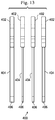
- Fig. 13 shows a side view of an exemplary blade set 400 usable with the collet assembly 116 disclosed herein.
- Each blade of the blade set 400 includes a proximal end 402 formed of a bulbous head, a shank 404, and distal cutting end 406.
- the proximal end 402 of each blade of the blade set 400 has the same thickness, but the thicknesses of the shanks 404 and cutting edges 406 varies. Because the proximal end 402 has the same thickness, the head of each of the blades of the set fits within the receiving groove 146 on the shank 126 of the driving shaft 118 with the same amount of clearance or play for consistency and repeatability.
- blade shank 404 and distal cutting edge 406 vary so that a surgeon may select a blade with the desired thickness for the particular surgical application.
- some blade sets may include blades that vary in thickness between .007 and .027 inch.
- the thickness of the proximal end 402 may be a result of an overmold as described above with respect to Figs. 10 and 11 , or alternatively, may be laminated or integrally formed of a single monolithic material.
- colored overmolding may identify the thickness of each cutting blade to permit a surgeon to distinguish one blade from another.
- Figs. 13 and 14 show components of an alternative collet assembly, with Fig. 14 showing an alternative sleeve 500 disposed about a shank 502 of a driving shaft, and with Fig. 15 showing a driving shaft head 550 separate from the shank 502.
- Protrusions 504 on the sleeve 500 and head 550 are spaced toward the respective perimeter edges 506, 552, in the manner discussed above. Accordingly, the description above regarding protrusion placement and placement of the receiving groove is equally applicable to the embodiment in Figs. 13 and 14 .
- the sleeve in Fig. 14 includes a distally facing blade contacting surface 508 having both protrusions 504 and recessed receiving openings 510 spaced toward the perimeter edge 506 in the manner discussed above.
- the protrusions 504 are rectangular or square rather than the cylindrical pins discussed above. It is contemplated that the driving shaft head 550 and the sleeve 500 would be used to secure a saw blade having corresponding shaped openings.
- the protrusions or receiving openings are on the driving shaft, while in other embodiments, the sleeve includes some protrusions and the driving shaft includes other protrusions.
- the head 550 is removable from the shank of the driving shaft, but may be attached using a fastener, such as a screw.
- the head 550 includes a proximally facing blade contacting surface 554 that includes protrusions 504 for engaging corresponding openings in a matching saw blade.
- the protrusions 504 are spaced toward the outer perimeter edge.
- Fig. 16 shows a sagittal saw 600 for driving the saw blade 104.
- the collet assembly 602 is arranged to secure the blade 104 in an axial direction relative to a saw handle 604. Accordingly, instead of having proximally and distally facing blade contacting surfaces, the collet assembly includes side-by-side blade contacting surfaces.
- the sagittal saw 600 includes protrusions disposed adjacent an exterior edge of the collet fixture, and the blade 104 is sized so that the outer perimeter of the head of the saw blade substantially corresponds to the edge of the collet assembly.
Landscapes
- Life Sciences & Earth Sciences (AREA)
- Health & Medical Sciences (AREA)
- Engineering & Computer Science (AREA)
- Mechanical Engineering (AREA)
- Surgery (AREA)
- Forests & Forestry (AREA)
- Wood Science & Technology (AREA)
- Animal Behavior & Ethology (AREA)
- Dentistry (AREA)
- Oral & Maxillofacial Surgery (AREA)
- Public Health (AREA)
- General Health & Medical Sciences (AREA)
- Veterinary Medicine (AREA)
- Heart & Thoracic Surgery (AREA)
- Medical Informatics (AREA)
- Molecular Biology (AREA)
- Biomedical Technology (AREA)
- Nuclear Medicine, Radiotherapy & Molecular Imaging (AREA)
- Epidemiology (AREA)
- Orthopedic Medicine & Surgery (AREA)
- Surgical Instruments (AREA)
Applications Claiming Priority (3)
| Application Number | Priority Date | Filing Date | Title |
|---|---|---|---|
| US12/136,956 US8920424B2 (en) | 2008-06-11 | 2008-06-11 | Micro-saw blade for bone-cutting surgical saws |
| EP09763249.1A EP2330988B1 (fr) | 2008-06-11 | 2009-05-28 | Lame de micro-scie pour des scies chirurgicales de coupe d'os |
| PCT/US2009/045378 WO2009151958A2 (fr) | 2008-06-11 | 2009-05-28 | Lame de micro-scie pour des scies chirurgicales de coupe d'os |
Related Parent Applications (2)
| Application Number | Title | Priority Date | Filing Date |
|---|---|---|---|
| EP09763249.1A Division-Into EP2330988B1 (fr) | 2008-06-11 | 2009-05-28 | Lame de micro-scie pour des scies chirurgicales de coupe d'os |
| EP09763249.1A Division EP2330988B1 (fr) | 2008-06-11 | 2009-05-28 | Lame de micro-scie pour des scies chirurgicales de coupe d'os |
Publications (1)
| Publication Number | Publication Date |
|---|---|
| EP3760141A1 true EP3760141A1 (fr) | 2021-01-06 |
Family
ID=41130172
Family Applications (3)
| Application Number | Title | Priority Date | Filing Date |
|---|---|---|---|
| EP20188879.9A Withdrawn EP3760141A1 (fr) | 2008-06-11 | 2009-05-28 | Jeu de lames de micro-scie pour des scies chirurgicales de coupe d'os |
| EP09763249.1A Active EP2330988B1 (fr) | 2008-06-11 | 2009-05-28 | Lame de micro-scie pour des scies chirurgicales de coupe d'os |
| EP20179802.2A Withdrawn EP3756592A1 (fr) | 2008-06-11 | 2009-05-28 | Lame de micro-scie pour des scies chirurgicales de coupe d'os |
Family Applications After (2)
| Application Number | Title | Priority Date | Filing Date |
|---|---|---|---|
| EP09763249.1A Active EP2330988B1 (fr) | 2008-06-11 | 2009-05-28 | Lame de micro-scie pour des scies chirurgicales de coupe d'os |
| EP20179802.2A Withdrawn EP3756592A1 (fr) | 2008-06-11 | 2009-05-28 | Lame de micro-scie pour des scies chirurgicales de coupe d'os |
Country Status (8)
| Country | Link |
|---|---|
| US (2) | US8920424B2 (fr) |
| EP (3) | EP3760141A1 (fr) |
| JP (1) | JP5731378B2 (fr) |
| CN (1) | CN102098970B (fr) |
| AU (1) | AU2009257762B2 (fr) |
| CA (3) | CA3040651C (fr) |
| ES (1) | ES2828096T3 (fr) |
| WO (1) | WO2009151958A2 (fr) |
Families Citing this family (59)
| Publication number | Priority date | Publication date | Assignee | Title |
|---|---|---|---|---|
| US8523868B2 (en) * | 2008-06-11 | 2013-09-03 | Medtronic Ps Medical, Inc. | Surgical cutting instrument with dual surface interlocking coupling arrangement |
| US8920424B2 (en) * | 2008-06-11 | 2014-12-30 | Medtronic Ps Medical, Inc. | Micro-saw blade for bone-cutting surgical saws |
| US20100186235A1 (en) * | 2009-01-26 | 2010-07-29 | Eric Davis Schwartz | Portable battery operated pipe cutter |
| US8939981B1 (en) | 2009-03-30 | 2015-01-27 | Keith Richard Anderson | Surgical saw blade for wedge osteotomies |
| WO2011083169A2 (fr) * | 2010-01-11 | 2011-07-14 | Zimmer Surgical Sa | Ensemble lame chirurgicale |
| JP5456556B2 (ja) * | 2010-04-23 | 2014-04-02 | 株式会社マキタ | 作業工具 |
| US8925931B2 (en) | 2010-04-29 | 2015-01-06 | Black & Decker Inc. | Oscillating tool |
| US9186770B2 (en) | 2010-04-29 | 2015-11-17 | Black & Decker Inc. | Oscillating tool attachment feature |
| US9073195B2 (en) | 2010-04-29 | 2015-07-07 | Black & Decker Inc. | Universal accessory for oscillating power tool |
| CN102259328B (zh) * | 2010-05-28 | 2014-07-30 | 南京德朔实业有限公司 | 用于将工作元件适配到动力工具轴端的适配器 |
| US9149923B2 (en) | 2010-11-09 | 2015-10-06 | Black & Decker Inc. | Oscillating tools and accessories |
| DE102011005821A1 (de) * | 2011-03-18 | 2012-09-20 | Robert Bosch Gmbh | Werkzeugspannvorrichtung |
| DE102012201667A1 (de) * | 2012-02-06 | 2013-08-08 | Robert Bosch Gmbh | Drehoszillationstrennwerkzeug für eine Werkzeugmaschine |
| US8936597B2 (en) * | 2012-02-06 | 2015-01-20 | Medtronic Ps Medical, Inc. | Deflectable finger connection feature on surgical saw blade |
| USD832666S1 (en) | 2012-07-16 | 2018-11-06 | Black & Decker Inc. | Oscillating saw blade |
| US9527146B2 (en) | 2013-10-04 | 2016-12-27 | Toronto Saw Works Inc. | Oscillating saw blades |
| EP3107479B1 (fr) | 2014-02-21 | 2025-08-27 | Intuitive Surgical Operations, Inc. | Articulations mécaniques, systèmes associés |
| KR102394198B1 (ko) * | 2014-04-02 | 2022-05-09 | 인튜어티브 서지컬 오퍼레이션즈 인코포레이티드 | 트위스팅 채널을 갖는 구동 부재 가이드 |
| US10549435B2 (en) * | 2014-12-31 | 2020-02-04 | Robert Bosch Tool Corporation | Oscillating tool with modified mounting interface for increasing cut depth |
| US10342553B2 (en) | 2015-01-21 | 2019-07-09 | Stryker European Holdings I, Llc | Surgical sagittal saw and complementary blade with features that fixedly hold the blade static to the saw |
| WO2016132320A1 (fr) * | 2015-02-19 | 2016-08-25 | Toronto Saw Works Inc. | Lames de scie avec des joints non-linéaire |
| EP3258859B1 (fr) * | 2015-02-19 | 2019-06-05 | Stryker Corporation | Scie et lame de scie chirurgique avec des dents de blockage deformable en montage |
| US10543000B2 (en) | 2015-07-02 | 2020-01-28 | AOD Holdings, LLC | Reciprocating surgical saw blade |
| US10011036B2 (en) * | 2015-11-09 | 2018-07-03 | Robert Bosch Tool Corporation | Blade and blade attachment system for an oscillating tool |
| CN105559848B (zh) * | 2015-12-29 | 2019-11-12 | 重庆西山科技股份有限公司 | 护鞘摆锯片 |
| CN105880732B (zh) * | 2016-05-11 | 2018-06-29 | 蔡锦霞 | 一种锯刀削切装置 |
| US10456142B2 (en) * | 2016-06-03 | 2019-10-29 | Mako Surgical Corp. | Surgical saw and saw blade for use therewith |
| USD816219S1 (en) * | 2016-08-25 | 2018-04-24 | Shukia Medical | Slap hammer |
| US10595879B1 (en) * | 2016-12-05 | 2020-03-24 | Palix Medical LLC | Blade for osteotome |
| US12508035B2 (en) * | 2016-12-05 | 2025-12-30 | Henry Schein, Inc. | Scoring blade and method for bone cement removal from intramedullary canal |
| US11364038B1 (en) * | 2016-12-05 | 2022-06-21 | Palix Medical LLC | Blades for osteotome |
| US12127749B1 (en) * | 2016-12-05 | 2024-10-29 | Henry Schein, Inc. | Cement removal blade for osteotome |
| US10265778B2 (en) | 2017-01-16 | 2019-04-23 | Black & Decker Inc. | Accessories for oscillating power tools |
| USD814900S1 (en) | 2017-01-16 | 2018-04-10 | Black & Decker Inc. | Blade for oscillating power tools |
| US10687824B2 (en) | 2017-07-21 | 2020-06-23 | Stryker European Holdings I, Llc | Surgical saw and saw blade for use therewith |
| CA3151238A1 (fr) | 2018-03-06 | 2019-09-12 | Conmed Corporation | Lame de scie chirurgicale gainee a roulements |
| WO2020003244A2 (fr) * | 2018-06-29 | 2020-01-02 | DePuy Synthes Products, Inc. | Lame de scie hybride |
| JP7382391B2 (ja) | 2018-07-27 | 2023-11-16 | ストライカー・コーポレイション | 外科用鋸ブレード及び熱管理システム |
| US11540863B2 (en) | 2018-07-31 | 2023-01-03 | GetSet Surgical SA | Spinal surgery systems and methods |
| USD931069S1 (en) | 2019-05-03 | 2021-09-21 | Tti (Macao Commercial Offshore) Limited | Blade |
| US12042209B2 (en) | 2019-05-16 | 2024-07-23 | Intuitive Surgical Operations, Inc. | Insert guide members for surgical instruments, and related devices, systems, and methods |
| USD927687S1 (en) | 2019-06-07 | 2021-08-10 | GetSet Surgical SA | Surgical instrument handle |
| USD926312S1 (en) | 2019-06-07 | 2021-07-27 | GetSet Surgical SA | Surgical instrument handle |
| USD896384S1 (en) | 2019-06-07 | 2020-09-15 | GetSet Surgical SA | Spinal fusion cage |
| USD926978S1 (en) | 2019-06-07 | 2021-08-03 | GetSet Surgical SA | Surgical instrument handle |
| USD953833S1 (en) | 2019-08-22 | 2022-06-07 | Milwaukee Electric Tool Corporation | Oscillating multi tool anchor |
| USD1101531S1 (en) | 2019-08-22 | 2025-11-11 | Milwaukee Electric Tool Corporation | Oscillating multi tool anchor |
| US11490898B2 (en) * | 2019-10-18 | 2022-11-08 | Depuy Synthes Products, Inc | Surgical saw blade |
| DE102019220365A1 (de) * | 2019-12-20 | 2021-06-24 | Robert Bosch Gesellschaft mit beschränkter Haftung | Sägewerkzeug |
| DE102019220528A1 (de) * | 2019-12-23 | 2021-06-24 | Robert Bosch Gesellschaft mit beschränkter Haftung | Werkzeugsystem |
| EP4185217A2 (fr) * | 2020-07-23 | 2023-05-31 | Stryker Corporation | Cartouche de lame de scie chirurgicale et dispositif d'accouplement associé |
| US11738398B2 (en) | 2020-11-18 | 2023-08-29 | Milwaukee Electric Tool Corporation | Accessory for an oscillating power tool |
| US12076802B2 (en) | 2021-01-22 | 2024-09-03 | Black & Decker Inc. | Accessories for oscillating power tools |
| US20230082586A1 (en) * | 2021-09-16 | 2023-03-16 | Treace Medical Concepts, Inc. | Multiple thickness saw blade for precision orthopedic cuts |
| USD1048844S1 (en) | 2022-07-22 | 2024-10-29 | Milwaukee Electric Tool Corporation | Anchor for an accessory attachable to an oscillating multi-tool |
| US12083610B2 (en) * | 2022-11-14 | 2024-09-10 | Robert Bosch Tool Corporation | Tool accessory mounting interface |
| US12194552B2 (en) * | 2022-11-14 | 2025-01-14 | Robert Bosch Tool Corporation | Tool accessory mounting interface |
| US12349925B2 (en) * | 2023-03-14 | 2025-07-08 | DePuy Synthes Products, Inc. | Powered surgical tool with an oscillating saw blade |
| US12446894B1 (en) | 2025-04-22 | 2025-10-21 | Stryker European Operations Limited | Saw blade for use in performing a medical procedure |
Citations (5)
| Publication number | Priority date | Publication date | Assignee | Title |
|---|---|---|---|---|
| US3977289A (en) * | 1973-01-08 | 1976-08-31 | National Research Development Corporation | Saws and blades therefor |
| US5366312A (en) * | 1993-08-18 | 1994-11-22 | Surgiquip, Inc. | Surgical saw blade attachment assembly |
| US5382249A (en) * | 1991-05-30 | 1995-01-17 | Synvasive Technology, Inc. | Adjustable surgical blade |
| US20060142774A1 (en) * | 2003-01-15 | 2006-06-29 | Biomet Manufacturing Corp. | Instrumentation for knee resection |
| WO2007041027A2 (fr) * | 2005-09-23 | 2007-04-12 | Synvasive Technology, Inc. | Lame de scie chirurgicale à action transversale et scie |
Family Cites Families (106)
| Publication number | Priority date | Publication date | Assignee | Title |
|---|---|---|---|---|
| US384979A (en) * | 1888-06-26 | Circular saw | ||
| US2138862A (en) * | 1936-12-22 | 1938-12-06 | Walter E Johnston | Utility tool |
| US2310409A (en) * | 1941-05-07 | 1943-02-09 | Martin M Ellman | Dental burr and hand-piece assembly |
| US2606366A (en) * | 1948-10-13 | 1952-08-12 | James B Stevens | Vibration dampening and insulating means for tools such as dental tools |
| US2685734A (en) * | 1952-03-14 | 1954-08-10 | Klein Ernest | Combined meat carving knife, bone saw, and meat fork |
| US3292237A (en) * | 1963-09-19 | 1966-12-20 | Universal American Corp | Vibration damping means for tools |
| GB1170845A (en) | 1967-08-11 | 1969-11-19 | Derouter Brothers Ltd | Improved Portable Power Operated Saw |
| US3678934A (en) | 1970-08-13 | 1972-07-25 | Stryker Corp | Power osteotome |
| GB1455566A (en) * | 1973-01-08 | 1976-11-17 | Nat Res Dev | Saws and blades therefor |
| US3927893A (en) | 1974-01-11 | 1975-12-23 | Skil Corp | Collet assembly for a reciprocating tool |
| US3905374A (en) * | 1974-01-28 | 1975-09-16 | American Sterilizer Co | Knee osteotomy blade |
| US3978862A (en) | 1974-08-26 | 1976-09-07 | Stryker Corporation | Surgical cutting device |
| US3943934A (en) | 1974-09-30 | 1976-03-16 | Minnesota Mining And Manufacturing Company | Quick release mechanism for surgical devices |
| US3952412A (en) | 1975-03-28 | 1976-04-27 | Rhodes William A | Oscillatory saw |
| US4020555A (en) * | 1976-04-12 | 1977-05-03 | Pevrick Engineering Co., Inc. | Connecting mechanism for a saw blade |
| US4106181A (en) | 1976-08-09 | 1978-08-15 | American Safety Equipment Corporation | Quick release mechanism for oscillating saw blade |
| US4386609A (en) | 1979-12-17 | 1983-06-07 | Minnesota Mining And Manufacturing Company | Attaching assembly for an osteotomy saw blade |
| CH653238A5 (de) | 1981-07-14 | 1985-12-31 | Richard Arnegger | Saegeblatt. |
| CH654196A5 (de) | 1981-10-13 | 1986-02-14 | Richard Arnegger | Saegeblatt einer oszillationssaege. |
| US4819334A (en) | 1983-05-06 | 1989-04-11 | Minnesota Mining And Manufacturing Company | Orbital saw device |
| US4617930A (en) | 1984-05-16 | 1986-10-21 | Queen's University At Kingston | Blade stiffener |
| DE8506874U1 (de) | 1985-03-09 | 1985-06-05 | Rems-Werk Christian Föll und Söhne GmbH & Co, 7050 Waiblingen | Sägeblatt für eine elektrische Stichsäge |
| AT382776B (de) * | 1985-05-07 | 1987-04-10 | Ender Hans Georg | Vorrichtung zur osteotomie und saegeblatt hiefuer |
| US4716881A (en) * | 1986-10-01 | 1988-01-05 | Silicon Technology Corporation | Blade mount for inner diameter saw blade |
| US5178626A (en) | 1989-01-13 | 1993-01-12 | Pappas Michael J | Stepped surgical saw blade |
| US5135533A (en) | 1989-02-10 | 1992-08-04 | Petersen Thomas D | Coated gall-resistant surgical saw blades |
| US5002555A (en) | 1989-02-10 | 1991-03-26 | Petersen Thomas D | Gall-resistant ribbed surgical saw blade |
| US5133728A (en) | 1990-01-05 | 1992-07-28 | Petersen Thomas D | Gall-resistant ribbed surgical saw blade |
| US5122142A (en) | 1990-09-13 | 1992-06-16 | Hall Surgical Division Of Zimmer, Inc. | Irrigating saw blade |
| DE4036904C1 (en) | 1990-11-20 | 1992-05-27 | Aesculap Ag, 7200 Tuttlingen, De | Osteotomy saw with oscillating blade retainer - which is free deposition surface, with blade locking pin compressible under deposition surface |
| USD337160S (en) | 1991-01-11 | 1993-07-06 | Stryker Corporation | Sagittal saw blade base |
| US5263972A (en) | 1991-01-11 | 1993-11-23 | Stryker Corporation | Surgical handpiece chuck and blade |
| US5092869A (en) | 1991-03-01 | 1992-03-03 | Biomet, Inc. | Oscillating surgical saw guide pins and instrumentation system |
| US5058273A (en) * | 1991-04-29 | 1991-10-22 | Streger Howell B | Vibratory carving tool kit |
| US7527628B2 (en) * | 1991-05-30 | 2009-05-05 | Synvasive Technology, Inc. | Surgical saw blade having at least one pair of opposed teeth shaped as right triangles |
| US6503253B1 (en) | 1993-11-16 | 2003-01-07 | Synvasive Technology, Inc. | Surgical saw blade |
| US6022353A (en) | 1991-05-30 | 2000-02-08 | Synasive Technology, Inc. | Surgical saw blade |
| US5265343A (en) * | 1992-01-27 | 1993-11-30 | Hall Surgical, Division Of Zimmer, Inc. | Blade collet |
| USD343247S (en) | 1992-02-03 | 1994-01-11 | Stryker Corporation | Surgical saw blade base |
| US5403318A (en) * | 1993-01-15 | 1995-04-04 | Boehringer Laboratories, Inc. | Apparatus and method for shaping bone |
| USRE36269E (en) | 1993-01-21 | 1999-08-17 | Minnesota Mining And Manufacturing Company | Saw blade retention system |
| USD346318S (en) | 1993-01-21 | 1994-04-26 | Stryker Corporation | Sagittal saw blade base |
| USD348194S (en) | 1993-04-01 | 1994-06-28 | Stryker Corporation | Sagittal saw blade base |
| US5306285A (en) | 1993-04-30 | 1994-04-26 | Komet Medical | Surgical saw blade |
| US5468247A (en) | 1993-05-26 | 1995-11-21 | Stryker Corporation | Saw blade for powered medical handpiece |
| USD353888S (en) | 1993-06-15 | 1994-12-27 | Surgiquip, Inc. | Surgical saw |
| US5507763A (en) | 1993-07-19 | 1996-04-16 | Hall Surgical | Surgical saw blade |
| EP0637433B1 (fr) * | 1993-08-03 | 1999-09-29 | Ricana AG | Lame de scie pour effectuer une coupe par oscillation ou par rotation |
| USD361029S (en) | 1994-02-07 | 1995-08-08 | Hall Sugrical | Sagittal saw blade |
| USD360946S (en) | 1994-02-18 | 1995-08-01 | Hall Surgical | Surgical saw blade hub |
| US5489285A (en) | 1994-02-23 | 1996-02-06 | Hall Surgical, Div. Of Zimmer, Inc. | Surgical saw blade and clamp |
| USD362065S (en) | 1994-05-19 | 1995-09-05 | Hall Surgical, Div. Of Zimmer, Inc. | Surgical saw blade hub |
| US5554165A (en) | 1995-02-09 | 1996-09-10 | Hall Surgical, Div. Of Zimmer, Inc. | Surgical blade and hub |
| US6944959B2 (en) | 1995-06-09 | 2005-09-20 | Black & Decker Inc. | Clamping arrangement for receiving a saw blade in multiple orientations |
| WO1997010765A1 (fr) | 1995-09-18 | 1997-03-27 | Exactech, Inc. | Scie chirurgicale a mouvements oscillatoires compenses |
| US5658304A (en) | 1995-10-18 | 1997-08-19 | Linvatec Corporation | Wrenchless and adapterless collet system for surgical blades |
| US5729904A (en) | 1995-11-01 | 1998-03-24 | Linvatec Corporation | Wrenchless collect for surgical blade |
| USD404485S (en) | 1995-11-21 | 1999-01-19 | Microaire Surgical Instruments | Surgical saw blade hub |
| US5697158A (en) | 1995-12-21 | 1997-12-16 | Minnesota Mining And Manufacturing Company | Orthopedic surgical device having a rotatable portion and lock |
| USD405177S (en) | 1995-12-22 | 1999-02-02 | Microaire Surgical Instruments, Inc. | Surgical saw blade hub |
| US5694693A (en) * | 1996-06-17 | 1997-12-09 | Microaire Surgical Instruments, Inc. | Universal saw blade hub |
| USD385164S (en) * | 1996-06-20 | 1997-10-21 | Microaire Surgical Instruments | Saw blade hub |
| USD394315S (en) | 1996-07-19 | 1998-05-12 | Fisher Michael G | Surgical saw blade hub |
| US5888200A (en) | 1996-08-02 | 1999-03-30 | Stryker Corporation | Multi-purpose surgical tool system |
| US5735866A (en) * | 1996-09-19 | 1998-04-07 | Linvatec Corporation | Adjustable length saw blade |
| US20010041524A1 (en) * | 1997-05-28 | 2001-11-15 | Marco Steiger | Material removing tool |
| US5870828A (en) * | 1997-06-04 | 1999-02-16 | Violex-Bic, S.A. | Utility knife system |
| USD406223S (en) | 1997-12-17 | 1999-03-02 | Linvatec Corporation | Oscillating saw blade |
| US6007541A (en) | 1998-01-09 | 1999-12-28 | Midas Rex, L.P. | Dual-bladed reciprocating bone saw |
| US6113619A (en) | 1998-10-05 | 2000-09-05 | Microaire Surgical Instruments | Two stage releasing interlocking system |
| USD459805S1 (en) | 1998-11-06 | 2002-07-02 | Microaire Surgical Instruments, Inc. | Surgical saw blade hub with tangs |
| USD455490S1 (en) | 1998-11-06 | 2002-04-09 | Microaire Surgical Instruments, Inc. | Surgical saw blade hub |
| US6113618A (en) | 1999-01-13 | 2000-09-05 | Stryker Corporation | Surgical saw with spring-loaded, low-noise cutting blade |
| KR100341540B1 (ko) * | 1999-08-19 | 2002-06-22 | 이희영 | 구강내 골절단용 톱 |
| US6302406B1 (en) | 2000-01-10 | 2001-10-16 | Microaire Surgical Instruments, Inc. | Connector assembly for a surgical saw blade |
| DE10010526C2 (de) | 2000-03-07 | 2002-01-17 | Thomas Hausmann | Sägeblatt für medizinische Anwendungen |
| DE10058894A1 (de) * | 2000-11-23 | 2002-06-06 | C & E Fein Gmbh & Co Kg | Werkzeug mit einem Halter zur Befestigung an einer Antriebswelle |
| JP2002166069A (ja) * | 2000-11-30 | 2002-06-11 | Ryobi Ltd | 刃物取付構造 |
| DE10112286C1 (de) * | 2001-03-14 | 2002-08-29 | Brasseler Gmbh & Co Kg Geb | Verfahren zur Herstellung eines chirurgischen Sägeblatts |
| DE10112288B4 (de) * | 2001-03-14 | 2006-09-07 | Gebr. Brasseler Gmbh & Co. Kg | Chirurgisches Sägeblatt mit Ausnehmungen im Arbeitsbereich |
| US6949110B2 (en) | 2001-06-22 | 2005-09-27 | Microaire Surgical Instruments, Inc. | Connector assembly for a surgical tool |
| US20040154133A1 (en) * | 2002-03-15 | 2004-08-12 | Trostel Specialty Elastomers Group, Inc. | Separable apparatus to cushion and dampen vibration and method |
| US20030172498A1 (en) * | 2002-03-15 | 2003-09-18 | Polzin Bruce C. | Apparatus to cushion and dampen vibration and method |
| US6656186B2 (en) | 2002-04-22 | 2003-12-02 | Molecular Metallurgy, Inc. | Bone saw blade and a method for manufacturing a bone saw blade |
| CN100506174C (zh) * | 2002-09-20 | 2009-07-01 | 医疗器械创新有限公司 | 具有可伸缩护套的外科手术刀 |
| US7833241B2 (en) * | 2002-11-12 | 2010-11-16 | Stryker Corporation | Surgical saw blade coupler |
| US7040023B2 (en) | 2002-11-25 | 2006-05-09 | Eastway Fair Company Limited | Toolless blade holder for a reciprocating tool |
| USD489823S1 (en) | 2003-01-14 | 2004-05-11 | Synvasive Technology, Inc. | Surgical saw blade hub |
| US7189239B2 (en) | 2003-01-14 | 2007-03-13 | Synvasive Technology, Inc. A California Corporation | Saw blade having a prearranged hub section |
| US7837690B2 (en) * | 2003-01-15 | 2010-11-23 | Biomet Manufacturing Corp. | Method and apparatus for less invasive knee resection |
| US7887542B2 (en) * | 2003-01-15 | 2011-02-15 | Biomet Manufacturing Corp. | Method and apparatus for less invasive knee resection |
| USD492412S1 (en) * | 2003-03-07 | 2004-06-29 | De Soutter Medical Ltd. | Surgical saw blade |
| US20040243136A1 (en) * | 2003-05-30 | 2004-12-02 | Parag Gupta | Dual cut surgical saw blade |
| WO2005056256A1 (fr) * | 2003-12-15 | 2005-06-23 | Synthes Ag Chur | Dispositif d'accouplement |
| US20050210686A1 (en) * | 2004-03-29 | 2005-09-29 | Jon Ritter | Reciprocating blade attachments including weighted balancing |
| US7497860B2 (en) | 2004-07-09 | 2009-03-03 | Stryker Corporation | Surgical sagittal saw including a handpiece and a removable blade assembly, the blade assembly including a guide bar, a blade head capable of oscillatory movement and a drive rod for actuating the blade head |
| US8062300B2 (en) * | 2006-05-04 | 2011-11-22 | Baxano, Inc. | Tissue removal with at least partially flexible devices |
| DE102004050798A1 (de) * | 2004-10-19 | 2006-04-20 | Robert Bosch Gmbh | Vorrichtung zum Befestigen eines Werkzeugs an einer oszillierend antreibbaren Antriebswelle einer Handwerkzeugmaschine |
| US20060123959A1 (en) * | 2004-11-19 | 2006-06-15 | Elite Medical Equipment, Llc | Cutter blade for cast saw |
| USD536791S1 (en) | 2005-03-09 | 2007-02-13 | Brasseler Usa Medical Llc | Tool hub |
| US20060206100A1 (en) * | 2005-03-09 | 2006-09-14 | Brasseler Usa Medical Llc | Surgical apparatus and power module for same, and a method of preparing a surgical apparatus |
| US20080119860A1 (en) * | 2006-11-21 | 2008-05-22 | Howmedica Osteonics Corp. | System for preparing bone for receiving an implant |
| KR20100127235A (ko) | 2008-02-18 | 2010-12-03 | 코닌클리즈케 필립스 일렉트로닉스 엔.브이. | 조명 기구의 국지화 |
| US8920424B2 (en) * | 2008-06-11 | 2014-12-30 | Medtronic Ps Medical, Inc. | Micro-saw blade for bone-cutting surgical saws |
| US8939981B1 (en) * | 2009-03-30 | 2015-01-27 | Keith Richard Anderson | Surgical saw blade for wedge osteotomies |
| US8672943B2 (en) * | 2009-05-12 | 2014-03-18 | Synvasive Technology, Inc. | Surgical saw blade device and system |
-
2008
- 2008-06-11 US US12/136,956 patent/US8920424B2/en active Active
-
2009
- 2009-05-28 EP EP20188879.9A patent/EP3760141A1/fr not_active Withdrawn
- 2009-05-28 AU AU2009257762A patent/AU2009257762B2/en not_active Ceased
- 2009-05-28 ES ES09763249T patent/ES2828096T3/es active Active
- 2009-05-28 CA CA3040651A patent/CA3040651C/fr not_active Expired - Fee Related
- 2009-05-28 CN CN200980128816.XA patent/CN102098970B/zh active Active
- 2009-05-28 JP JP2011513548A patent/JP5731378B2/ja not_active Expired - Fee Related
- 2009-05-28 EP EP09763249.1A patent/EP2330988B1/fr active Active
- 2009-05-28 WO PCT/US2009/045378 patent/WO2009151958A2/fr not_active Ceased
- 2009-05-28 EP EP20179802.2A patent/EP3756592A1/fr not_active Withdrawn
- 2009-05-28 CA CA2727400A patent/CA2727400C/fr not_active Expired - Fee Related
- 2009-05-28 CA CA3040660A patent/CA3040660C/fr not_active Expired - Fee Related
-
2014
- 2014-12-23 US US14/581,328 patent/US9414845B2/en active Active
Patent Citations (5)
| Publication number | Priority date | Publication date | Assignee | Title |
|---|---|---|---|---|
| US3977289A (en) * | 1973-01-08 | 1976-08-31 | National Research Development Corporation | Saws and blades therefor |
| US5382249A (en) * | 1991-05-30 | 1995-01-17 | Synvasive Technology, Inc. | Adjustable surgical blade |
| US5366312A (en) * | 1993-08-18 | 1994-11-22 | Surgiquip, Inc. | Surgical saw blade attachment assembly |
| US20060142774A1 (en) * | 2003-01-15 | 2006-06-29 | Biomet Manufacturing Corp. | Instrumentation for knee resection |
| WO2007041027A2 (fr) * | 2005-09-23 | 2007-04-12 | Synvasive Technology, Inc. | Lame de scie chirurgicale à action transversale et scie |
Also Published As
| Publication number | Publication date |
|---|---|
| EP2330988A2 (fr) | 2011-06-15 |
| WO2009151958A2 (fr) | 2009-12-17 |
| CA3040651C (fr) | 2021-09-07 |
| CN102098970B (zh) | 2014-03-12 |
| AU2009257762B2 (en) | 2015-01-22 |
| CA3040651A1 (fr) | 2009-12-17 |
| JP5731378B2 (ja) | 2015-06-10 |
| CN102098970A (zh) | 2011-06-15 |
| WO2009151958A3 (fr) | 2010-03-04 |
| CA3040660A1 (fr) | 2009-12-17 |
| ES2828096T3 (es) | 2021-05-25 |
| AU2009257762A1 (en) | 2009-12-17 |
| US20150112347A1 (en) | 2015-04-23 |
| CA2727400A1 (fr) | 2009-12-17 |
| CA2727400C (fr) | 2019-06-18 |
| EP2330988B1 (fr) | 2020-09-23 |
| EP3756592A1 (fr) | 2020-12-30 |
| CA3040660C (fr) | 2021-03-23 |
| US20090312762A1 (en) | 2009-12-17 |
| JP2011523883A (ja) | 2011-08-25 |
| US8920424B2 (en) | 2014-12-30 |
| US9414845B2 (en) | 2016-08-16 |
Similar Documents
| Publication | Publication Date | Title |
|---|---|---|
| US10856885B2 (en) | Surgical cutting instrument with near-perimeter interlocking coupling arrangement | |
| US9414845B2 (en) | Micro-saw blade for bone-cutting surgical saws | |
| EP3081175B1 (fr) | Instrument de coupe chirurgical à double surface | |
| AU2014280901B2 (en) | Micro-saw blade for bone-cutting surgical saws |
Legal Events
| Date | Code | Title | Description |
|---|---|---|---|
| PUAI | Public reference made under article 153(3) epc to a published international application that has entered the european phase |
Free format text: ORIGINAL CODE: 0009012 |
|
| STAA | Information on the status of an ep patent application or granted ep patent |
Free format text: STATUS: THE APPLICATION HAS BEEN PUBLISHED |
|
| AC | Divisional application: reference to earlier application |
Ref document number: 2330988 Country of ref document: EP Kind code of ref document: P |
|
| AK | Designated contracting states |
Kind code of ref document: A1 Designated state(s): AT BE BG CH CY CZ DE DK EE ES FI FR GB GR HR HU IE IS IT LI LT LU LV MC MK MT NL NO PL PT RO SE SI SK TR |
|
| STAA | Information on the status of an ep patent application or granted ep patent |
Free format text: STATUS: REQUEST FOR EXAMINATION WAS MADE |
|
| 17P | Request for examination filed |
Effective date: 20210706 |
|
| RBV | Designated contracting states (corrected) |
Designated state(s): AT BE BG CH CY CZ DE DK EE ES FI FR GB GR HR HU IE IS IT LI LT LU LV MC MK MT NL NO PL PT RO SE SI SK TR |
|
| GRAP | Despatch of communication of intention to grant a patent |
Free format text: ORIGINAL CODE: EPIDOSNIGR1 |
|
| STAA | Information on the status of an ep patent application or granted ep patent |
Free format text: STATUS: GRANT OF PATENT IS INTENDED |
|
| INTG | Intention to grant announced |
Effective date: 20240422 |
|
| STAA | Information on the status of an ep patent application or granted ep patent |
Free format text: STATUS: THE APPLICATION IS DEEMED TO BE WITHDRAWN |
|
| 18D | Application deemed to be withdrawn |
Effective date: 20240823 |