EP3760236B1 - Validation du nettoyage dans un dispositif de remplissage de récipients - Google Patents
Validation du nettoyage dans un dispositif de remplissage de récipients Download PDFInfo
- Publication number
- EP3760236B1 EP3760236B1 EP20184297.8A EP20184297A EP3760236B1 EP 3760236 B1 EP3760236 B1 EP 3760236B1 EP 20184297 A EP20184297 A EP 20184297A EP 3760236 B1 EP3760236 B1 EP 3760236B1
- Authority
- EP
- European Patent Office
- Prior art keywords
- filling
- temperature
- temperature sensor
- container
- treatment
- Prior art date
- Legal status (The legal status is an assumption and is not a legal conclusion. Google has not performed a legal analysis and makes no representation as to the accuracy of the status listed.)
- Active
Links
Images
Classifications
-
- B—PERFORMING OPERATIONS; TRANSPORTING
- B67—OPENING, CLOSING OR CLEANING BOTTLES, JARS OR SIMILAR CONTAINERS; LIQUID HANDLING
- B67C—CLEANING, FILLING WITH LIQUIDS OR SEMILIQUIDS, OR EMPTYING, OF BOTTLES, JARS, CANS, CASKS, BARRELS, OR SIMILAR CONTAINERS, NOT OTHERWISE PROVIDED FOR; FUNNELS
- B67C7/00—Concurrent cleaning, filling, and closing of bottles; Processes or devices for at least two of these operations
- B67C7/0073—Sterilising, aseptic filling and closing
-
- B—PERFORMING OPERATIONS; TRANSPORTING
- B67—OPENING, CLOSING OR CLEANING BOTTLES, JARS OR SIMILAR CONTAINERS; LIQUID HANDLING
- B67C—CLEANING, FILLING WITH LIQUIDS OR SEMILIQUIDS, OR EMPTYING, OF BOTTLES, JARS, CANS, CASKS, BARRELS, OR SIMILAR CONTAINERS, NOT OTHERWISE PROVIDED FOR; FUNNELS
- B67C3/00—Bottling liquids or semiliquids; Filling jars or cans with liquids or semiliquids using bottling or like apparatus; Filling casks or barrels with liquids or semiliquids
- B67C3/001—Cleaning of filling devices
- B67C3/002—Cleaning of filling devices using cups or dummies to be placed under the filling heads
-
- A—HUMAN NECESSITIES
- A61—MEDICAL OR VETERINARY SCIENCE; HYGIENE
- A61L—METHODS OR APPARATUS FOR STERILISING MATERIALS OR OBJECTS IN GENERAL; DISINFECTION, STERILISATION OR DEODORISATION OF AIR; CHEMICAL ASPECTS OF BANDAGES, DRESSINGS, ABSORBENT PADS OR SURGICAL ARTICLES; MATERIALS FOR BANDAGES, DRESSINGS, ABSORBENT PADS OR SURGICAL ARTICLES
- A61L2/00—Disinfection or sterilisation of materials or objects, in general; Accessories therefor
- A61L2/02—Disinfection or sterilisation of materials or objects, in general; Accessories therefor using physical processes
- A61L2/04—Heat
- A61L2/06—Hot gas
- A61L2/07—Steam
-
- A—HUMAN NECESSITIES
- A61—MEDICAL OR VETERINARY SCIENCE; HYGIENE
- A61L—METHODS OR APPARATUS FOR STERILISING MATERIALS OR OBJECTS IN GENERAL; DISINFECTION, STERILISATION OR DEODORISATION OF AIR; CHEMICAL ASPECTS OF BANDAGES, DRESSINGS, ABSORBENT PADS OR SURGICAL ARTICLES; MATERIALS FOR BANDAGES, DRESSINGS, ABSORBENT PADS OR SURGICAL ARTICLES
- A61L2/00—Disinfection or sterilisation of materials or objects, in general; Accessories therefor
- A61L2/26—Accessories
- A61L2/28—Devices for testing the effectiveness or completeness of sterilisation or disinfection, e.g. indicators which change colour
-
- B—PERFORMING OPERATIONS; TRANSPORTING
- B67—OPENING, CLOSING OR CLEANING BOTTLES, JARS OR SIMILAR CONTAINERS; LIQUID HANDLING
- B67C—CLEANING, FILLING WITH LIQUIDS OR SEMILIQUIDS, OR EMPTYING, OF BOTTLES, JARS, CANS, CASKS, BARRELS, OR SIMILAR CONTAINERS, NOT OTHERWISE PROVIDED FOR; FUNNELS
- B67C3/00—Bottling liquids or semiliquids; Filling jars or cans with liquids or semiliquids using bottling or like apparatus; Filling casks or barrels with liquids or semiliquids
- B67C3/001—Cleaning of filling devices
-
- B—PERFORMING OPERATIONS; TRANSPORTING
- B67—OPENING, CLOSING OR CLEANING BOTTLES, JARS OR SIMILAR CONTAINERS; LIQUID HANDLING
- B67C—CLEANING, FILLING WITH LIQUIDS OR SEMILIQUIDS, OR EMPTYING, OF BOTTLES, JARS, CANS, CASKS, BARRELS, OR SIMILAR CONTAINERS, NOT OTHERWISE PROVIDED FOR; FUNNELS
- B67C3/00—Bottling liquids or semiliquids; Filling jars or cans with liquids or semiliquids using bottling or like apparatus; Filling casks or barrels with liquids or semiliquids
- B67C3/007—Applications of control, warning or safety devices in filling machinery
-
- B—PERFORMING OPERATIONS; TRANSPORTING
- B67—OPENING, CLOSING OR CLEANING BOTTLES, JARS OR SIMILAR CONTAINERS; LIQUID HANDLING
- B67C—CLEANING, FILLING WITH LIQUIDS OR SEMILIQUIDS, OR EMPTYING, OF BOTTLES, JARS, CANS, CASKS, BARRELS, OR SIMILAR CONTAINERS, NOT OTHERWISE PROVIDED FOR; FUNNELS
- B67C3/00—Bottling liquids or semiliquids; Filling jars or cans with liquids or semiliquids using bottling or like apparatus; Filling casks or barrels with liquids or semiliquids
- B67C3/02—Bottling liquids or semiliquids; Filling jars or cans with liquids or semiliquids using bottling or like apparatus
- B67C3/06—Bottling liquids or semiliquids; Filling jars or cans with liquids or semiliquids using bottling or like apparatus using counterpressure, i.e. filling while the container is under pressure
-
- B—PERFORMING OPERATIONS; TRANSPORTING
- B67—OPENING, CLOSING OR CLEANING BOTTLES, JARS OR SIMILAR CONTAINERS; LIQUID HANDLING
- B67C—CLEANING, FILLING WITH LIQUIDS OR SEMILIQUIDS, OR EMPTYING, OF BOTTLES, JARS, CANS, CASKS, BARRELS, OR SIMILAR CONTAINERS, NOT OTHERWISE PROVIDED FOR; FUNNELS
- B67C3/00—Bottling liquids or semiliquids; Filling jars or cans with liquids or semiliquids using bottling or like apparatus; Filling casks or barrels with liquids or semiliquids
- B67C3/02—Bottling liquids or semiliquids; Filling jars or cans with liquids or semiliquids using bottling or like apparatus
- B67C3/22—Details
-
- B—PERFORMING OPERATIONS; TRANSPORTING
- B67—OPENING, CLOSING OR CLEANING BOTTLES, JARS OR SIMILAR CONTAINERS; LIQUID HANDLING
- B67C—CLEANING, FILLING WITH LIQUIDS OR SEMILIQUIDS, OR EMPTYING, OF BOTTLES, JARS, CANS, CASKS, BARRELS, OR SIMILAR CONTAINERS, NOT OTHERWISE PROVIDED FOR; FUNNELS
- B67C7/00—Concurrent cleaning, filling, and closing of bottles; Processes or devices for at least two of these operations
-
- A—HUMAN NECESSITIES
- A61—MEDICAL OR VETERINARY SCIENCE; HYGIENE
- A61L—METHODS OR APPARATUS FOR STERILISING MATERIALS OR OBJECTS IN GENERAL; DISINFECTION, STERILISATION OR DEODORISATION OF AIR; CHEMICAL ASPECTS OF BANDAGES, DRESSINGS, ABSORBENT PADS OR SURGICAL ARTICLES; MATERIALS FOR BANDAGES, DRESSINGS, ABSORBENT PADS OR SURGICAL ARTICLES
- A61L2202/00—Aspects relating to methods or apparatus for disinfecting or sterilising materials or objects
- A61L2202/10—Apparatus features
- A61L2202/14—Means for controlling sterilisation processes, data processing, presentation and storage means, e.g. sensors, controllers, programs
-
- B—PERFORMING OPERATIONS; TRANSPORTING
- B67—OPENING, CLOSING OR CLEANING BOTTLES, JARS OR SIMILAR CONTAINERS; LIQUID HANDLING
- B67C—CLEANING, FILLING WITH LIQUIDS OR SEMILIQUIDS, OR EMPTYING, OF BOTTLES, JARS, CANS, CASKS, BARRELS, OR SIMILAR CONTAINERS, NOT OTHERWISE PROVIDED FOR; FUNNELS
- B67C3/00—Bottling liquids or semiliquids; Filling jars or cans with liquids or semiliquids using bottling or like apparatus; Filling casks or barrels with liquids or semiliquids
- B67C3/02—Bottling liquids or semiliquids; Filling jars or cans with liquids or semiliquids using bottling or like apparatus
- B67C3/22—Details
- B67C2003/228—Aseptic features
-
- B—PERFORMING OPERATIONS; TRANSPORTING
- B67—OPENING, CLOSING OR CLEANING BOTTLES, JARS OR SIMILAR CONTAINERS; LIQUID HANDLING
- B67C—CLEANING, FILLING WITH LIQUIDS OR SEMILIQUIDS, OR EMPTYING, OF BOTTLES, JARS, CANS, CASKS, BARRELS, OR SIMILAR CONTAINERS, NOT OTHERWISE PROVIDED FOR; FUNNELS
- B67C3/00—Bottling liquids or semiliquids; Filling jars or cans with liquids or semiliquids using bottling or like apparatus; Filling casks or barrels with liquids or semiliquids
- B67C3/02—Bottling liquids or semiliquids; Filling jars or cans with liquids or semiliquids using bottling or like apparatus
- B67C3/22—Details
- B67C3/26—Filling-heads; Means for engaging filling-heads with bottle necks
- B67C2003/2688—Means for filling containers in defined atmospheric conditions
- B67C2003/2697—Means for filling containers in defined atmospheric conditions by enclosing the container partly in a chamber
Definitions
- the present invention relates to a device for filling a container with a filling product, preferably in a beverage filling plant, and to a method for cleaning and/or sterilizing such a device.
- the resulting temperature of the filling valves is maintained and monitored over a certain period of time in order to achieve a predetermined sterilization effect, as can be seen, for example, from the EN 10 2010 031 873 A1 , EN 10 2013113621 A1 , EP 3 015 418 A1 , JP2000355397A and EP 0 418 079 A1 is known.
- a baffle with a small opening can be swiveled in front of the outlet of the filling valve during thermal sterilization and sealed to it.
- a steam jet then emerges through the small opening of the baffle, the dynamic pressure of which is detected by a pressure sensor arranged below the baffle.
- the temperature is determined indirectly by recording the upstream saturated steam pressure and the steam throughput or steam pressure in the filling valve via the differential pressure thus recorded per filling valve.
- the pressure sensor is usually installed statically below the height of the baffle. The pressure of the steam jet emerging from the baffle is recorded when the respective filling valve is moved over the pressure sensor.
- the filling of the filling product takes place in a filling room or clean room of the filling device in which, in comparison to the If there is a reduced microbial load and/or excess pressure in the environment and thus the degree of sterility compared to the environment is increased, the installation of additional parts and components, such as a cover, a lifting and swiveling device for the cover, a pressure sensor and the like, is disadvantageous from a hygienic point of view, since the additional components installed in the clean room lead to increased cleaning effort.
- thermocouple Another option for temperature monitoring according to the state of the art is to monitor each individual filling valve with a thermocouple, which is usually integrated in the filling valve or arranged on the cover.
- thermocouple This requires one thermocouple per filling valve or per cover and correspondingly complex wiring, which is installed in the rotating part in rotary machines.
- the filling/closing system described above does not require flow meters at the individual filling stations, since the filling can be controlled exclusively by the vacuum pressure level in the evacuated container and the filling pressure.
- the device according to the invention serves to fill a container with a filling product.
- the device is particularly preferably used in a beverage filling plant for filling beverages, such as water, carbonated or non-carbonated, soft drinks, beer or mixed drinks.
- the device has at least one filling station with a filling element for introducing the filling product into the container to be filled and a treatment device for treating at least part of the filling station, in particular the filling element, with a treatment medium that is different from the filling product.
- the treatment device is primarily used to clean and/or sterilize the device, in particular the filling elements. Accordingly, a distinction is made here between “regular operation” of the device, in which the containers are filled, and “treatment operation” in which the cleaning and/or sterilization takes place.
- the device further comprises at least one temperature sensor for detecting a temperature of at least one section of the filling station and a control device which is designed to determine a reference value which corresponds to a temperature of the treatment medium at a location deviating from the at least one filling station, to compare the temperature detected by the temperature sensor with the reference value during the treatment of the filling element and to determine therefrom whether there is sufficient treatment of the filling element.
- temperature recorded by the temperature sensor includes not only temperature values in standard physical temperature units but also parameters that are derived from the detected temperature of the relevant filling station and are therefore an alternative measure for the detected temperature.
- the control device can standardize or otherwise convert or process the received measurement data in order to abstract from the specific structure of the temperature sensor, specific physical units and the like. This applies equally to the reference value and its determination or recording.
- the measured filling station temperature in particular the temperature of the filling element
- a reference value during cleaning and/or sterilization
- temperature values at different points in the device are compared with each other during treatment, which means that the verification or monitoring can essentially be carried out solely from the actual state of the system. It is therefore carried out in a particularly simple, self-sufficient and reliable manner in terms of construction and process technology.
- the treatment medium for cleaning and/or sterilization is or preferably comprises steam, particularly preferably hot steam.
- the treatment medium may also comprise hydrogen peroxide or peracetic acid, preferably in combination with alcohols, such as ethanol.
- the device preferably has a product vessel in fluid communication with the filling element and a reference temperature sensor which is designed to determine the temperature of the medium in the product vessel.
- the product vessel functions as a filling product reservoir during normal operation and as a reservoir for a treatment medium, for example in the form of hot steam or a cleaning liquid, during treatment operation, i.e. cleaning or sterilization operation.
- the control device is then preferably designed to use the temperature detected by the reference temperature sensor as a reference value or to derive it from it.
- the reference value can be obtained particularly easily and reliably directly from the supply or source of the treatment medium. If the temperature of the monitored filling element roughly corresponds to the reference value or deviates only slightly from it, for example if it is within a permissible range below the boiler temperature, it can be assumed that the filling element is being sufficiently supplied with treatment medium and that the treatment is proceeding successfully. Otherwise, the filling element in question may not be being sufficiently supplied with treatment medium and appropriate countermeasures can be taken. For example, in the latter case, it is possible to issue an error message, open the filling element to discharge condensate and/or increase the throughput of treatment medium, or direct more treatment medium to the corresponding filling element.
- the control device is preferably designed to determine the reference value from the temperature of at least a first filling station or to derive it, to compare the temperature recorded by the temperature sensor of a second filling station with the reference value and to determine from this whether the second filling device has been adequately treated.
- first and second only serve to linguistically distinguish between two filling stations to be compared; a particular order or sequence is not implied by this.
- the temperatures of different filling stations are compared with one another in order to check the plausibility of the treatment of the cavities. If the temperature of the monitored filling element essentially corresponds to the temperatures of one, several or all other filling elements, it can be assumed that the treatment is successful. Otherwise, the filling element in question may not be sufficiently supplied with treatment medium and appropriate countermeasures can be taken, such as one or more of those mentioned above. In this case, the treatment can be verified solely from a comparison of the filling stations with one another, which further simplifies the structure of the device. In order to obtain a more accurate result, this measure can of course be combined with other measures, such as the detection and processing of the boiler temperature described above.
- the at least one temperature sensor is designed as a contactless temperature sensor, for example in the form of a pyrometer and/or an infrared camera. This also applies to any reference temperature sensor.
- non-contact temperature sensor is provided for non-contact temperature detection, the reliability and maintainability of the device can be further increased, as a non-contact sensor can be arranged outside the filling station and is therefore easier to access.
- the cleaning effort can be reduced, as fewer components need to be cleaned overall and, in particular, cleaning of parts that move relative to one another and their seals is eliminated.
- Non-contact temperature measurement also prevents contamination of the filling element and thus of the filling product-carrying paths of the device by a contacting temperature sensor. Accordingly, the device can be constructed more compactly and hygienically overall. This also ensures greater process reliability, as with non-contact measuring sensors, the sensor cannot become detached from the surface to be measured or become abrasion-resistant or deformed, as is the case with contacting sensors.
- the contactless measurement of the temperature can preferably be carried out on an outside of the filling element, preferably in the area of a valve seat of the filling element, so that the temperature of the filling element can be directly recorded and monitored without contact. It can be assumed that when, for example, hot steam is passed through the When the temperature is measured at the filling device, the paths in contact with the filling product also have at least the same temperature as the filling device.
- the non-contact temperature sensor is preferably directed at an outside or outer surface of the corresponding filling element.
- the non-contact temperature sensor preferably records the temperature of the filling element in the area of the valve seat. This allows the temperature of the filling element to be recorded easily and precisely.
- the contactless temperature sensor is designed as an infrared camera, it can record the temperature of several filling elements simultaneously, so that the structure of the device is even simpler and the process reliability is even higher. Using appropriate evaluation software, the temperature can be determined for each individual filling element.
- the at least one temperature sensor comprises an electronic device, such as an RFID chip, for wirelessly transmitting the measured temperature data to the control device.
- an electronic device such as an RFID chip
- wired data transmission can be dispensed with, which further simplifies the structure of the device and further increases its flexibility.
- the sensor can also be installed in places that are difficult to access, which makes it particularly suitable for use with the filler/closer described below.
- a smaller number of temperature sensors is provided than filling stations, preferably only a single temperature sensor is provided for detecting the temperatures of all filling stations to be monitored, wherein the corresponding filling elements are movable relative to the temperature sensors.
- the temperature sensor is preferably arranged in a fixed position so that it can also be connected to the control device particularly easily. This means that the transfer of the respective signal from a rotating part to a stationary part is not necessary.
- the temperature of the respective filling stations can preferably be detected as they move past the at least one temperature sensor, wherein the filling stations are arranged on a transport device, preferably a rotary carousel.
- each filling station is assigned (at least) one temperature sensor.
- each filling station is assigned (at least) one temperature sensor.
- This allows the temperature of each filling station, in particular of each filling element, to be recorded particularly precisely.
- permanent recording and thus permanent monitoring of the temperature(s) is possible, so that the cleaning and/or sterilization process can be carried out particularly safely.
- This also ensures that the temperature of each filling station can be recorded at any time, thus enabling particularly precise monitoring and control/regulation of the treatment process.
- the device is designed for filling and closing the container, in this case also referred to herein as a "filler/closer”, wherein each filling station in this case preferably comprises: a head chamber which is designed to at least partially accommodate the container, preferably a mouth portion of the container, and which is sealable from the external environment; the filling element which is designed in the head chamber for evacuating the container and introducing the filling product into the evacuated container, wherein the filling product is preferably under an overpressure; and a closing element with a closing head which is designed to accommodate a closure and to close the container with the closure in the head chamber and without prior relief to ambient pressure, wherein the closing head is preferably movable between a retracted position and a closing position.
- evacuation does not necessarily imply the aim of making the negative pressure in the container as close as possible to a perfect vacuum. Rather, evacuation can serve to build up a specific negative pressure.
- negative pressure and “positive pressure” are to be understood in relation to one another.
- the positive pressure of the filling product, under which it is preferably filled, can correspond to atmospheric pressure, but is preferably above it.
- the container is preferably evacuated to a negative pressure P low with an absolute pressure of 0.5 to 0.05 bar, preferably 0.3 to 0.1 bar, particularly preferably about 0.1 bar.
- the overpressure is above atmospheric pressure, for example at an absolute pressure of 1.1 bar to 6 bar.
- the container is evacuated in such a way that at When filling with the filling product, essentially no gas is displaced by the filling product and accordingly no gas has to flow out of the interior of the container. Rather, the entire mouth cross-section of the container can be used to introduce the filling product. In other words, when filling, there is only a flow of filling product directed into the container, but no opposite fluid flow.
- the container is filled in a flash and closed in a timely and spatially integrated manner, making it extremely hygienic.
- the filling element preferably has a mouth section, wherein the filling in this case is preferably also carried out in such a way that the mouth section for filling the container is brought into sealing fluid communication with the container in the head chamber, the head chamber is sealed from the outside environment and brought to an overpressure, and the mouth section is detached from the container after the filling process has ended, whereby the overpressure of the head chamber acts on the filling product in the container.
- the container is filled suddenly, while at the same time overfoaming after filling, in particular after the filling element is removed from the container mouth, is prevented.
- the verification of the cleaning and/or sterilization of the filling elements described here is particularly suitable for fillers/cappers, especially for sudden filling, since the complex structure of the filling stations, including the filling element and capper, makes conventional monitoring difficult. In particular, there is no need to resort to flow measurement of the treatment medium.
- the temperature sensor is arranged outside the head chamber so that a structural modification of the filling station for treatment monitoring is not necessary.
- the temperature sensor can be embedded in the capping head.
- the temperature measurement takes place directly in the head chamber, which is also flushed or exposed to treatment medium when the filling device is open, for example by means of one or more RFID sensors that transmit the temperature data wirelessly to the control device.
- RFID sensors that transmit the temperature data wirelessly to the control device.
- Such a temperature sensor can be embedded in the surface of the capping head, for example, meaning that the filling device can remain structurally unchanged.
- the temperature sensor preferably measures a temperature at the filling device, but the temperature can also be determined indirectly, for example by measuring the temperature at the capping head. Due to the structural integration of the filling device and capping device in the case of the filler/capper, the capping head of the capping device can thus be used to Temperature detection can be used synergistically, for example by embedding an RFID sensor in the capping head.
- the above-mentioned object is further achieved by a method for treating, preferably cleaning and/or sterilizing, a filling element of at least one filling station of a device as previously discussed, for introducing a filling product into a container to be filled, preferably in a beverage filling plant.
- the method comprises: applying a treatment medium, preferably hot steam or a tempered cleaning liquid, to at least part of the filling element; detecting a temperature of at least one section of the filling station by means of a temperature sensor; determining a reference value that corresponds to a temperature of the treatment medium at a location other than the at least one filling station; comparing the temperature detected by the temperature sensor with the reference value; and determining from the comparison whether the filling element has been adequately treated.
- a treatment medium preferably hot steam or a tempered cleaning liquid
- the temperature of the treatment medium in a product vessel which is in fluid communication with the filling device and/or the temperature of one or more other filling stations is preferably used as a reference value or is derived therefrom.
- the temperature of the at least one filling station is preferably measured without contact, for example by means of a temperature sensor in the form of a pyrometer and/or an infrared camera.
- the method is particularly preferably carried out in a filler/closer.
- the temperature sensor can detect the temperature of the closer head, the closer head being moved into the head chamber during treatment.
- the closer head is moved back and forth between a retracted position and a closing position during treatment, whereby the closer head takes on the temperature of the head chamber, caused by the treatment medium introduced via the filling element.
- the control device is preferably designed to control or regulate the treatment of the at least one filling station based on the comparison result. This makes it possible to achieve particularly efficient and resource-saving treatment. If the control device is also designed in such a way that the filling element to be monitored is opened during the treatment process if the comparison indicates inadequate treatment, treatment medium can also be saved. On the other hand, condensate arising from a possible drop in temperature can be let out, preferably blown out, and the interior of the filling station, in particular the filling element, can be rinsed with treatment medium for as long as or dampened until the comparison again indicates adequate treatment.
- the opening and closing of the filling device or its filling valve takes place alternately.
- the opening/closing of the filling valve is timed depending on the comparison. Consequently, treatment medium is only released via the open filling valve when it is required for heating and/or draining condensate.
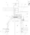
- the Figure 1 is a schematic sectional view of a device 1 for filling a container with a filling product, also referred to herein as "filling device", in a filling product filling plant, preferably a beverage filling plant.
- the filling device 1 is designed in a rotary design and has a rotatable rotary carousel 4 and a part 9 which is static relative to the rotary carousel 4.
- a clean room 8 is provided in which the filling product is filled into the container in a controlled atmosphere.
- the clean room 8 is formed by a clean room cover 8a formed on the rotary carousel 4 and clean room walls not shown in the figures.
- a plurality of filling stations are arranged around the circumference of the rotary carousel 4 in order to be able to produce a continuous flow of filled containers on the rotary carousel 4 in the filling product filling system.
- the filling elements 2 penetrate the clean room cover 8a in such a way that only their product outlet 2d and the filling valve base piece 6 open into the clean room 8.
- the filling valve base piece 6 can alternatively be designed as a centering bell if containers are filled in the pressed state.
- a plurality of container receptacles 5 are arranged for receiving the containers to be filled, with each container receptacle 5 being assigned to a filling element 2.
- the filling elements 2 are each connected via a product line 3 to a media distributor (not shown), via which both the filling product from a filling product reservoir (cf. Figure 4 ) and a treatment medium, for example in the form of hot steam or a cleaning liquid, can be supplied from a sterilization device.
- the filling elements 2 have a valve cone 2b above their product outlet 2d in the valve interior 2e, which is arranged to be movable in the direction of the longitudinal axis of the filling element 2 and which can be lowered into a valve seat 2a to close the filling element 2.
- the valve cone 2b is lifted out of the valve seat 2a so that an annular gap is formed between the valve cone 2b and the valve seat 2a, through which the filling product or a treatment medium can then reach the product outlet 2d and exit from it.
- a temperature sensor 7 is arranged on the stationary part 9 and can determine the temperature of a filling element 2 moving past without contact.
- the contactless temperature sensor 7 is provided at a fixed position of the filling device 1. It is positioned in such a way that it detects the temperature of the filling element 2 in the area of the valve cone 2a on an outer side 2c of the filling element 2.
- the contactless temperature sensor 7 is designed in such a way that it can determine the temperature of one of the plurality of filling elements 2 as they move past the contactless temperature sensor 7. In other words, the contactless temperature sensor 7 can differentiate the temperatures of the individual filling elements 2 from one another. The contactless Temperature sensor 7 is thus able to successively detect the temperature of each filling element 2 that is guided past it by the rotary carousel 4.
- the rotary carousel 4 preferably rotates at a reduced speed.
- the measured value received at a given time can be assigned to the respective filling station or the respective filling device 2.
- the non-contact temperature sensor 7 is also provided with a Figure 1 control device not shown (cf. Figure 4 ) and/or control or regulating device, by means of which the treatment, for example the cleaning and/or sterilization of the filling elements 2, can be controlled or regulated and the temperature of the filling elements 2 can be monitored.
- a Figure 1 control device not shown (cf. Figure 4 ) and/or control or regulating device, by means of which the treatment, for example the cleaning and/or sterilization of the filling elements 2, can be controlled or regulated and the temperature of the filling elements 2 can be monitored.
- the contactless temperature sensor 7 is designed, for example, as an infrared camera. Alternatively, however, it can also be designed as a pyrometer or in the form of another contactless temperature sensor.
- the filling elements 2 are preferably initially held in an open position. In order to keep the consumption of sterilization steam as low as possible, the filling element 2 is then partially or completely closed so that the sterilization steam is essentially present in the valve interior 2e.
- a cover or sterilization cap can be arranged in front of the product outlet 2d in order to achieve a defined volume flow of the sterilization medium.
- the respective filling element 2 is opened, for example, the condensate that may have formed due to the temperature drop is discharged from the valve interior 2e and fresh hot steam is supplied to heat the filling element 2.
- treatment medium is only released via the opened filling element when it is required to heat up the filling element 2 and/or drain condensate. In this way, treatment medium can be saved.
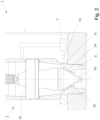
- the Figure 2 shows schematically a detailed sectional view of a filling element 2 of a filling device 1 for filling a filling product into a container to be filled in an alternative embodiment.
- the filling device 1 shown here essentially corresponds to that of the Figure 1 .
- a contactless temperature sensor 7 is arranged on each of the plurality of filling elements 2. According to this embodiment, the temperature sensors 7 are thus provided on the rotating part, i.e. the rotary carousel 4.
- the non-contact temperature sensors 7 are designed as pyrometers. Alternatively, other non-contact temperature sensors can also be used.
- the filling element 2 is designed in such a way that the contactless temperature sensor 7 in the area of the valve seat 2a on an outer side 2c of the filling element 2 detects the temperature of the filling element 2.
- the reference symbol 7a indicates the measuring beam of the pyrometer.
- the temperature sensor can also be implemented by a contact-measuring sensor which is either in contact with a section of the filling element 2 and/or comes into contact with the treatment medium in the region of the filling element 2, in particular in the region of the filling product outlet 2d.
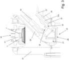
- a device for filling and closing containers also referred to herein as a "filler/closer”, according to a further embodiment is shown in detail in the Figure 3
- the device falls under the terms “filling device” or “device for filling a container with a filling product” used above.
- the filler/sealer has a filling element 20 which is arranged in the Figure 3 shown process stage protrudes into a head chamber 10.
- the filling element 20 has, accommodated in a filling element housing 21: a filling product line 22; a filling valve 23 which is arranged at the lower, ie downstream end of the filling product line 22; a gas line 24; and a gas valve 25 which is arranged at the lower end of the gas line 24.
- the container can be flushed and/or pre-pressurized with a gas, such as inert gas, nitrogen and/or carbon dioxide, via the gas line 24 and the gas valve 25.
- a gas such as inert gas, nitrogen and/or carbon dioxide
- the interior of the container can be set to a desired pressure, in particular evacuated.
- the gas line 24 can be a multi-channel construction, for example, can comprise several gas lines through a pipe-in-pipe structure in order to physically separate the supply of one or more gases into the container and/or the discharge of gas from the container, if necessary.
- the gas valve 25 comprises, for example, a gas valve cone and a gas valve seat, which are designed to regulate the gas flow.
- the gas valve cone can be switched via an actuator (not shown).
- the filling product line 22 is preferably designed as a ring line that extends essentially concentrically to the gas line 24.
- the filling valve 23 comprises, for example, a filling valve cone and a filling valve seat that are designed to regulate the flow of the filling product.
- the filling valve 23 is designed to enable the filling product flow to be completely shut off. In the simplest case, the filling valve 23 has two positions, one open and one completely closed. For this purpose, the filling valve 23 can be switched via an actuator (not shown).
- the gas valve 25 and the filling valve 23 are actuated via actuators that are not described in detail. It should be noted that the gas valve 25 and the filling valve 23 can be operatively connected to one another, so that, for example, one actuator can be set up for joint use in order to simplify the structure of the filling element 20 and increase reliability.
- the filling element 20 has a mouth section 26 at the outlet end of the media, which is designed so that the container mouth can be brought into a seal against the mouth section 26.
- the mouth section 26 preferably has a centering bell with a suitably shaped contact rubber.
- the filling element 20 with the mouth section 26 is designed for so-called wall filling, in which the filling product flows downwards along the container wall after exiting the mouth section 26.
- the filling product line 22 and the mouth section 26 are preferably designed or have corresponding means so that the filling product is given a swirl during filling, whereby the filling product is driven outwards due to centrifugal force and flows downwards in a spiral movement after exiting the mouth section 26.
- the filling element 20 can have one or more dosing valves 27, 28 which open into a dosing chamber 22a, whereby a rapid change of type can be realized, essentially without changeover time.
- the dosing valves 27, 28 are preferred embodiments or designs of dosing supply lines.
- the dosing valves 27, 28 can be dispensed with if necessary, so that, for example, only corresponding dosing lines or channels open into the dosing chamber 22a.
- the dosing chamber 22a can be a section or suitably shaped part of the filling product line 22. Via the dosing valves 27, 28, to which corresponding dosing lines are connected, one or more dosing components, for example syrup, pulp, flavors, etc., can be added to a main component, for example water or beer, introduced into the dosing chamber 22a via the filling product line 22.
- a dosing component for example water or beer
- dosing valves 27, 28 are present, these and their supply lines are preferably also flushed with treatment medium in the treatment operation described below.
- the filling device 20 is at least partially movable so that the Figure 3 shown arm-like section of the filling element 20 can be moved into the head chamber 10 and either withdrawn therein or partially or even completely removed therefrom. This makes it possible to press the container mouth against the mouth section 26 of the filling element 20 for the filling process and then, after completion of the filling process, to withdraw the filling element 20 so far that the container can be closed in the head chamber 10.
- the filling device 20 can be moved without the atmosphere of the head chamber 10 being exposed to uncontrolled external influences.
- means such as inflatable seals are provided for sealing.
- the head chamber pressure after completion of the filling process can be greater than the pressure of the external environment, whereby the penetration of contaminants into the head chamber 10 can be almost completely ruled out.
- the head chamber 10 can be located in a clean room or form one.
- the filler/closer also has a closing element 30 for closing the container. Since in addition to the filling element 20, further components such as the head chamber 10 and the closing element 30 are spatially integrated as a structural unit on the rotary carousel (in the Figure 3 not shown), the filling station in this case is realized by this structural unit.
- the closing member 30 has a closing head 31 which projects into the head chamber 10 and in the present embodiment is essentially vertically movable. Like the filling member 20, the closing member 30 is sealed off from the wall of the head chamber 10 in order to avoid contamination or uncontrolled impairment of the atmosphere inside the head chamber 10 by external influences.
- the closing member 30 is designed and configured to receive and hold a closure V on the closing head 31.
- the closing head 31 can have a magnet, whereby a closure V, especially if it is a metallic crown cap, can be received centrally in a structurally simple manner and placed on the container mouth to close the container.
- the closure V can be held by suitable gripping or clamping means can be grasped, held and applied to the container mouth, so that the concept presented here is also applicable in particular for plastic closures, screw caps, etc.
- the closing head 31 is designed to be movable in the up/down direction, wherein it is arranged substantially coaxially to the container mouth in order to be able to reliably apply the closure V to the container.
- a closure V can be introduced into the head chamber 10, for example from a sorting unit and a feed chute.
- the head chamber 10 can be part of the capping member 30 and can perform a relative movement to the closure feed, for example the feed chute or a transfer arm, with the capping head 31 picking and holding a closure V from the closure feed.
- closure of the container can also take place at another location.
- closure preferably takes place immediately after filling and in the head chamber 10 under overpressure, as explained below.
- the container To fill the container, it is raised relative to the head chamber 10, for example by means of a Figure 3 lifting device (not shown) which has a plate-shaped support which moves against the container from below and lifts it.
- the head chamber 10 can be lowered and moved onto the container mouth.
- the lifting device can be used to stabilize the container during filling and closing.
- a combination of both procedures ie lowering the head chamber 10 and lifting the container using the lifting device, is also possible.
- the container mouth is now introduced into the head chamber 10 and the head chamber 10 is sealed from the outside environment.
- the container mouth is pressed sealingly against the mouth section 26 of the filling element 20 extended into the filling position.
- the mouth section 26 of the filling element 20 thus marks the end position of the container stroke and/or the lowering of the head chamber 10.
- the capping head 31 receives the closure V and moves into the head chamber 10.
- the sealing of the head chamber 10 against the environment and against the container or its mouth area can be achieved by suitable means, such as inflatable seals.
- gas is preferably supplied to the head chamber 10.
- the head chamber 10 is sealed on all sides, which allows a suitable internal pressure to be built up in the head chamber 10.
- this preferably corresponds to the filling pressure or saturation pressure of the carbon dioxide or is higher, which effectively prevents the filling product from foaming up or over-foaming after the filling process has ended.
- the gas supply for the head chamber 10 can be controlled by means of a head chamber valve, in the Figure 3 not shown.
- the gas supply can be at least partially integrated in the filling element 20.
- the filling element 20 according to the embodiment of the Figure 3 a head chamber gas line 29.
- the head chamber gas line 29, in particular its outlet into the head chamber 10 can be designed so that the escaping gas jet hits the underside of the closure V when the filling element 20 is in the filling position. In this way, the closure V is cleaned simultaneously during the filling process.
- Carbon dioxide is preferably used as the gas, but another medium, such as sterile air, can also be used.
- the filling element 20 is retracted and the closing head 31 continues its downward movement until the container mouth is reached and closed.
- the terms "negative pressure” and “positive pressure” are to be understood relative to each other.
- the overpressure P high generated in step c) can correspond to atmospheric pressure, but is preferably higher.
- the container before the filling product is introduced, the container is preferably evacuated to a negative pressure P low with an absolute pressure of 0.5 to 0.05 bar, preferably 0.3 to 0.1 bar, particularly preferably about 0.1 bar.
- the overpressure P high is preferably above atmospheric pressure, for example at an absolute pressure of 1.1 bar to 6 bar.
- the container is evacuated in such a way that when it is filled with the filling product, essentially no gas is displaced by the filling product and accordingly no gas has to flow out of the interior of the container. Instead, the entire mouth cross-section of the container can be used to introduce the filling product. In other words, when filling, there is only a flow of filling product directed into the container, but no opposite fluid flow, which can further accelerate the filling process.
- the temperature measurement explained below during treatment operation, ie cleaning and/or sterilization operation, can be carried out by means of a stationary or movable temperature sensor 7 (in the Figure 3 not shown), for example an infrared camera, outside the head chamber 10.
- a stationary or movable temperature sensor 7 for example an infrared camera
- the construction and hygiene of the head chamber 10 as well as the filling element 20 and closing element 30 are not impaired.
- the radiation from the surface of the closing element 30 immersed in the head chamber 10 can be measured using a temperature sensor 7 implemented as an IR camera.
- the temperature sensor 7 preferably measures a temperature on the filling element 20, but the temperature can also be determined indirectly, for example by measuring the temperature on the closing head 31.
- the temperature sensor 7 is therefore at least designed to detect a temperature at a suitable portion of the filling station in question.
- the temperature measurement can be carried out by means of a temperature sensor 7' in the head chamber 10, for example by means of one or more RFID sensors, which transmit the temperature data to the control device described below.
- a temperature sensor 7 ⁇ can, for example, be embedded in the surface of the capping head 31.
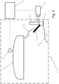
- the Figure 4 is a schematic representation of a filling device 1 for explaining the treatment operation, in particular CIP and/or SIP operation.
- the filling device 1 has in detail, for example, the structure of the embodiments described above according to the Figures 1 to 3 on.
- the filling elements 2, 20 are each connected via a product line 3, 22 to a product vessel 40, which functions as a filling product reservoir in regular operation and as a reservoir for treatment medium, for example in the form of hot steam or cleaning liquid, in treatment operation.
- the Product vessel 40 has a reference temperature sensor 41 which is designed to determine the temperature of the medium contained therein.
- the reference temperature sensor 41 can operate without contact or can be in contact with the product vessel 40 or the medium in the product vessel 40.
- the reference temperature sensor 41 and the temperature sensors 7 and/or 7' are communicatively connected to a control device 43, which is an electronic device for monitoring and/or controlling the treatment process.
- the data transmission can be wireless or wired.
- the treatment medium runs from the product vessel 40 via the product line 3, 22 to the filling device 2, 20.
- the gas line 24 and the head chamber 10 are also flushed or filled with the treatment medium.
- the treatment medium is transported away via a return line 42, to which a negative pressure is applied, for example.
- the transported treatment medium can be disposed of or processed for complete or partial reuse.
- the temperature of the filling elements 2, 20 is measured by means of one or more of the described temperature sensors 7, 7'.
- the cleaning or sterilization can be validated.
- the reference value corresponds to a temperature of the treatment medium at a location other than the filling station to be monitored.
- the reference value preferably corresponds to the boiler temperature or is derived from it.
- the reference value can correspond to the measured temperature of one or more other filling elements 2, 20 or be derived from it.
- the comparison can be made at regular intervals in order to determine changes in the temperature at the filling element 2, 20 to be monitored.
- the closing member 30 can be moved between the retracted position and closing position, whereby the closing member 30 also experiences a temperature increase that can be detected by the embedded temperature sensor 7'.
- the treatment medium has a temperature of, for example, 80°C to 90°C and in the case of acid cleaning, 40°C to 50°C, so that during treatment operation there is usually an increase in temperature at the filling element.
- each filling station The idea of how to verify the cleaning and/or sterilization of each filling station is based on detecting the rising temperature of each station, in particular of each filling element 2, 20, during the treatment and comparing it with the temperature in the flow, preferably the boiler temperature. If the temperature of the monitored filling element 2, 20 is within a permissible range below the boiler temperature, it can be assumed that the treatment is successful. However, if the temperature of the monitored filling element 2, 20 is well below the boiler temperature, in particular outside the aforementioned permissible range, the relevant filling element 2, 20 is not being adequately supplied with treatment medium.
- a comparison between the individual filling elements 2, 20 can be used to check the plausibility of the treatment of the cavities. If the temperature of the monitored filling element 2, 20 essentially corresponds to the temperatures of one, several or all of the other filling elements - an average value can also be used here - it can be assumed that the treatment is successful. Otherwise, the filling element 2, 20 in question is not being supplied with sufficient treatment medium.
- the relevant filling element 2, 20 is not sufficiently supplied with treatment medium, countermeasures can be taken. For example, it is possible to issue an error message, to open the filling element 2, 20 to discharge condensate and/or to increase the throughput of treatment medium, or to direct more treatment medium to the relevant filling element. It is particularly preferred that the opening and closing of the filling element or its filling valve 2, 20 takes place alternately. In this case, the opening/closing of the filling valve 2, 20 can be timed depending on the comparison. Consequently, treatment medium is only discharged via the open filling valve 2, 20 when it is required to heat up and/or discharge condensate.
- the evaluation of the temperature differences during cleaning and/or sterilization described here makes it possible to verify the cleaning or sterilization even without measuring the flow rate of the treatment medium. Furthermore, it is not necessary to determine whether the treatment is sufficient or insufficient based on the temporal development of the recorded temperature and by applying predetermined and preset threshold values. Instead, temperature values at different points on the device 1 are compared with each other during the treatment, whereby the verification or monitoring can essentially be carried out solely from the actual state of the system. It is therefore carried out in a structurally and procedurally particularly simple, self-sufficient and reliable manner. In addition, it is not necessary to equip each individual filling element 2, 20 with temperature sensors 7, 7'.
Landscapes
- Health & Medical Sciences (AREA)
- Epidemiology (AREA)
- Life Sciences & Earth Sciences (AREA)
- Animal Behavior & Ethology (AREA)
- General Health & Medical Sciences (AREA)
- Public Health (AREA)
- Veterinary Medicine (AREA)
- Filling Of Jars Or Cans And Processes For Cleaning And Sealing Jars (AREA)
Claims (15)
- Dispositif (1) permettant le remplissage d'un récipient avec un produit de remplissage, de préférence dans une installation de remplissage de boissons, dans lequel le dispositif (1) présente :au moins un poste de remplissage comportant un organe de remplissage (2, 20) destiné à introduire le produit de remplissage dans le récipient à remplir ;un dispositif de traitement permettant le traitement, de préférence le nettoyage et/ou la stérilisation, d'au moins une partie de l'organe de remplissage (2, 20) au moyen d'un milieu de traitement ;au moins un capteur de température (7, 7`) permettant de détecter une température d'au moins une section du poste de remplissage ; etun appareil de contrôle (43) qui est configuré pour déterminer une valeur de référence correspondant à une température du milieu de traitement à un endroit différent de l'au moins un poste de remplissage, pour comparer, pendant le traitement de l'organe de remplissage (2, 20), la température détectée par le capteur de température (7, 7`) avec la valeur de référence et pour déterminer, sur cette base, si un traitement suffisant de l'organe de remplissage (2, 20) a lieu.
- Dispositif (1) selon la revendication 1, caractérisé en ce qu'il présente en outre une chaudière à produit (40) en liaison fluidique avec l'organe de remplissage (2, 20) et un capteur de température de référence (41) configuré pour définir la température du milieu présent dans la chaudière à produit (40), dans lequel l'appareil de contrôle (43) est configuré pour utiliser la température détectée par le capteur de température de référence (41) comme valeur de référence ou pour en déduire une valeur de référence.
- Dispositif (1) selon la revendication 1 ou 2, caractérisé en ce que plusieurs postes de remplissage comportant respectivement un organe de remplissage (2, 20) permettant d'introduire le produit de remplissage dans des récipients à remplir sont prévus et l'appareil de contrôle (43) est configuré pour utiliser la valeur de référence à partir de la température d'au moins un premier poste de remplissage ou pour en déduire la valeur de référence, pour comparer la température d'un second poste de remplissage, détectée par le capteur de température (7, 7`), avec la valeur de référence et pour déterminer, sur cette base, si un traitement suffisant du second organe de remplissage (2, 20) a lieu.
- Dispositif (1) selon l'une des revendications précédentes, caractérisé en ce que l'au moins un capteur de température (7, 7`) est conçu sous la forme d'un capteur de température (7) sans contact, de préférence sous la forme d'un pyromètre et/ou d'une caméra infrarouge.
- Dispositif (1) selon l'une des revendications précédentes, caractérisé en ce que l'au moins un capteur de température (7, 7') comprend un appareil électronique, de préférence une puce RFID, pour la transmission sans fil des données de température mesurées à l'appareil de contrôle (43).
- Dispositif (1) selon l'une des revendications précédentes, caractérisé en ce qu'un plus petit nombre de capteurs de température (7, 7') que de postes de remplissage est prévu, de préférence un seul capteur de température (7) permettant de détecter les températures de tous les postes de remplissage à surveiller, dans lequel les organes de remplissage (2, 20) correspondants sont mobiles par rapport aux capteurs de température (7).
- Dispositif (1) selon la revendication 6, caractérisé en ce que la température des postes de remplissage respectifs peut être détectée lors d'un passage de ceux-ci devant l'au moins un capteur de température (7), dans lequel les postes de remplissage sont disposés sur un dispositif de transport, de préférence un carrousel rotatif (4).
- Dispositif (1) selon l'une des revendications 1 à 5, caractérisé en ce qu'une pluralité de postes de remplissage et une pluralité de capteurs de température (7, 7`) sont prévues, dans lequel chaque poste de remplissage est respectivement associé à au moins un capteur de température (7).
- Dispositif (1) selon l'une des revendications précédentes, caractérisé en ce qu'il est conçu pour remplir et fermer le récipient, dans lequel chaque poste de remplissage présente :une chambre de tête (10) qui est conçue pour recevoir au moins partiellement le récipient, de préférence une section d'embouchure du récipient, et qui peut être rendue étanche par rapport à l'environnement extérieur ;l'organe de remplissage (20) qui est conçu dans la chambre de tête (10) pour mettre sous vide le récipient ainsi que pour introduire le produit de remplissage dans le récipient mis sous vide, dans lequel le produit de remplissage est de préférence soumis à une surpression ; etun organe de fermeture (30) comportant une tête de fermeture (31) qui est conçue pour recevoir un élément de fermeture et pour fermer le récipient dans la chambre de tête (10) et sans décharge préalable à pression ambiante au moyen de l'élément de fermeture, dans lequel la tête de fermeture (31) est de préférence mobile entre une position rétractée et une position de fermeture.
- Dispositif (1) selon la revendication 9, caractérisé en ce que l'au moins un capteur de température (7, 7`) est disposé à l'extérieur de la chambre de tête (10) ou est intégré dans la tête de fermeture (31).
- Dispositif (1) selon la revendication 9 ou 10, caractérisé en ce que l'au moins un capteur de température (7, 7`) est configuré pour détecter la température de la tête de fermeture (31).
- Procédé permettant le traitement, de préférence le nettoyage et/ou la stérilisation, d'un organe de remplissage (2, 20) d'au moins un poste de remplissage d'un dispositif selon l'une des revendications 1 à 11 destiné à introduire un produit de remplissage dans un récipient à remplir, de préférence dans une installation de remplissage de boissons, dans lequel le procédé présente :l'exposition d'au moins une partie de l'organe de remplissage (2, 20) à un milieu de traitement, de préférence de la vapeur chaude ou un liquide de nettoyage tempéré ;la détection d'une température d'au moins une section du poste de remplissage à l'aide d'un capteur de température (7, 7`) ;la détermination, par l'appareil de contrôle (43), d'une valeur de référence correspondant à une température du milieu de traitement à un endroit différent de l'au moins un poste de remplissage ;la comparaison, par l'appareil de contrôle (43), de la température détectée par le capteur de température (7, 7`) avec la valeur de référence ;
etla détermination, à partir de la comparaison, du fait de savoir si un traitement suffisant de l'organe de remplissage (2, 20) a lieu. - Procédé selon la revendication 12, caractérisé en ce que la température du milieu de traitement dans une chaudière à produit (40), laquelle chaudière à produit est en liaison fluidique avec l'organe de remplissage (2, 20), et/ou la température d'un ou de plusieurs autres postes de remplissage sont utilisées comme valeur de référence ou pour en déduire la valeur de référence.
- Procédé selon la revendication 12 ou 13, caractérisé en ce que la température de l'au moins un poste de remplissage est mesurée sans contact, de préférence à l'aide d'un capteur de température (7) sous la forme d'un pyromètre et/ou d'une caméra infrarouge.
- Procédé selon l'une des revendications 12 à 14, caractérisé en ce qu'il est mis en oeuvre au moyen d'un dispositif selon l'une des revendications 1 à 11, dans lequel le procédé est de préférence mis en oeuvre au moyen d'un dispositif selon la revendication 11, le capteur de température (7, 7') détecte la température de la tête de fermeture (31), et la tête de fermeture (31) est déplacée dans la chambre de tête (10) pendant le traitement, de préférence en va-et-vient entre une position rétractée et une position de fermeture.
Applications Claiming Priority (1)
| Application Number | Priority Date | Filing Date | Title |
|---|---|---|---|
| DE102019118114.3A DE102019118114A1 (de) | 2019-07-04 | 2019-07-04 | Reinigungsvalidierung in einer Vorrichtung zum Abfüllen von Behältern |
Publications (3)
| Publication Number | Publication Date |
|---|---|
| EP3760236A1 EP3760236A1 (fr) | 2021-01-06 |
| EP3760236C0 EP3760236C0 (fr) | 2024-09-04 |
| EP3760236B1 true EP3760236B1 (fr) | 2024-09-04 |
Family
ID=71522971
Family Applications (1)
| Application Number | Title | Priority Date | Filing Date |
|---|---|---|---|
| EP20184297.8A Active EP3760236B1 (fr) | 2019-07-04 | 2020-07-06 | Validation du nettoyage dans un dispositif de remplissage de récipients |
Country Status (3)
| Country | Link |
|---|---|
| EP (1) | EP3760236B1 (fr) |
| CN (1) | CN112174077B (fr) |
| DE (1) | DE102019118114A1 (fr) |
Families Citing this family (5)
| Publication number | Priority date | Publication date | Assignee | Title |
|---|---|---|---|---|
| DE102019135261A1 (de) * | 2019-12-19 | 2021-06-24 | Krones Ag | Vorrichtung und Verfahren zum Befüllen eines Behälters mit einem Füllprodukt |
| DE102021125824A1 (de) * | 2021-10-05 | 2023-04-06 | Ampack Gmbh | Abdeckvorrichtung für eine Abfüllstation und Abfüllstation mit einer solchen Abdeckvorrichtung |
| WO2023066669A1 (fr) * | 2021-10-20 | 2023-04-27 | Sidel Participations | Appareil de surveillance automatisé et procédé de surveillance de procédures de nettoyage dans une machine de remplissage |
| DE102023112893A1 (de) * | 2023-05-16 | 2024-11-21 | Khs Gmbh | Verfahren zum Sterilisieren eines Füllventils |
| DE102024110982A1 (de) * | 2024-04-19 | 2025-10-23 | Khs Gmbh | Behälterbehandlungsvorrichtung zum Behandeln von Behältern |
Family Cites Families (11)
| Publication number | Priority date | Publication date | Assignee | Title |
|---|---|---|---|---|
| US4989649A (en) * | 1989-09-14 | 1991-02-05 | Automatic Liquid Packaging, Inc. | Fill machine sterilization process |
| DE4232323A1 (de) * | 1992-09-26 | 1994-03-31 | Seitz Enzinger Noll Masch | Vorrichtung zur Überwachung der Wärmebehandlung bzw. Sterilisation von Flaschen o. dgl. Behälter bei einer Behälter-Behandlungsmaschine |
| JP2000355397A (ja) * | 1999-06-15 | 2000-12-26 | Shibuya Kogyo Co Ltd | 充填装置 |
| JP4603321B2 (ja) * | 2004-09-03 | 2010-12-22 | アサヒ飲料株式会社 | 容器洗浄装置 |
| DE102010031873A1 (de) * | 2010-07-21 | 2012-01-26 | Krones Aktiengesellschaft | Vorrichtung und Verfahren zum Befüllen von Behältnissen mit Reinigungseinrichtung |
| JP5574025B1 (ja) * | 2013-06-25 | 2014-08-20 | 大日本印刷株式会社 | 飲料供給系配管の殺菌方法及び装置 |
| DE102013113621A1 (de) * | 2013-12-06 | 2015-06-11 | Krones Ag | Füllorgan zum Abfüllen eines Füllprodukts in einen Behälter sowie Verfahren zum Reinigen des Füllorgans |
| DE102014104873A1 (de) * | 2014-04-04 | 2015-10-08 | Krones Ag | Verfahren und Vorrichtung zum Befüllen eines Behälters mit einem Füllprodukt |
| CN105607580A (zh) * | 2016-02-29 | 2016-05-25 | 同福碗粥股份有限公司 | 智能数显温控系统及其粥类灌装封口机 |
| DE102016123965A1 (de) * | 2016-12-09 | 2018-06-14 | Krones Ag | Füllvorrichtung zum Abfüllen eines Füllprodukts in einen zu befüllenden Behälter in einer Füllproduktabfüllanlage |
| DE102017114387A1 (de) * | 2017-06-28 | 2019-01-03 | Krones Ag | Vorrichtung zum Behandeln eines Behälters in einer Füllproduktabfüllanlage |
-
2019
- 2019-07-04 DE DE102019118114.3A patent/DE102019118114A1/de active Pending
-
2020
- 2020-07-03 CN CN202010637046.XA patent/CN112174077B/zh active Active
- 2020-07-06 EP EP20184297.8A patent/EP3760236B1/fr active Active
Also Published As
| Publication number | Publication date |
|---|---|
| EP3760236C0 (fr) | 2024-09-04 |
| CN112174077B (zh) | 2023-01-10 |
| EP3760236A1 (fr) | 2021-01-06 |
| CN112174077A (zh) | 2021-01-05 |
| DE102019118114A1 (de) | 2021-01-07 |
Similar Documents
| Publication | Publication Date | Title |
|---|---|---|
| EP3760236A1 (fr) | Validation du nettoyage dans un dispositif de remplissage de récipients | |
| EP0590505B1 (fr) | Appareil de commande du traitement ou de la stérilisation à chaud de bouteilles ou récipients dans une machine de traitement de ceux-ci | |
| DE69520445T2 (de) | System und verfahren zum sterilen verpacken von getränken | |
| EP3551569B1 (fr) | Dispositif de remplissage destiné à remplir un contenant à remplir d'un produit de remplissage dans une installation de remplissage en produit de remplissage | |
| EP2345524B1 (fr) | Appareil et méthode de mesure pour déterminer au moins une valeur de paramètre pour le fonctionnement d'une machine de moulage par soufflage | |
| EP0539791B1 (fr) | Procédé et dispositif pour remplir des bouteilles ou des récipients similaires avec un produit liquide | |
| EP2392906B1 (fr) | Dispositif et procédé de vérification de l'effet nettoyant d'un dispositif de nettoyage | |
| EP2138446A1 (fr) | Système de remplissage à rayon libre | |
| WO2009030545A1 (fr) | Procédé et dispositif de manipulation stérile ou aseptique de contenants | |
| DE4031472A1 (de) | Vorrichtung zum sterilisieren, fuellen und verschliessen einer fuelloeffnung | |
| DE102006023764A1 (de) | Verfahren sowie Vorrichtung zum Sterilisieren von Flaschen oder dergleichen Behälter | |
| EP2392516A1 (fr) | Installation de traitement de récipient et procédé de sécurisation de la qualité pour des récipients fabriqués à l'aide d'une installation de traitement de récipient | |
| DE102008006770B4 (de) | Vorrichtung sowie Verfahren zum Aufschäumen von in Behältern abgefüllten Produkten | |
| DE102007028471A1 (de) | Vorrichtung zum Behandeln von Gefäßen in einem Gefäßdesinfektionssystem | |
| EP3699100A1 (fr) | Dispositif et procédé de fabrication de récipients remplis | |
| DE102019133131A1 (de) | Getränke-Abfüllanlage | |
| EP3699101B1 (fr) | Dispositif et procédé de fabrication de récipients remplis | |
| EP4302965B1 (fr) | Dispositif et procédé de traitement de récipients avec dispositif de détection pour mesurer le niveau de remplissage | |
| EP3699102A1 (fr) | Dispositif et procédé de fabrication de récipients remplis | |
| EP3808696B1 (fr) | Validation du nettoyage dans un dispositif de remplissage de récipients | |
| EP4001206B1 (fr) | Dispositif multifonction permettant de remplir des récipients d'un produit de remplissage | |
| EP3838839B1 (fr) | Dispositif et procédé de remplissage d'un récipient d'un produit de remplissage | |
| EP1094003B1 (fr) | Dispositif pour fermer des récipients remplis, avec un bouchon de fermeture | |
| EP2949585B1 (fr) | Procede et dispositif de remplissage de bouteilles | |
| EP3795531A1 (fr) | Contrôle de qualité lors du remplissage d'un récipient avec un produit de remplissage |
Legal Events
| Date | Code | Title | Description |
|---|---|---|---|
| PUAI | Public reference made under article 153(3) epc to a published international application that has entered the european phase |
Free format text: ORIGINAL CODE: 0009012 |
|
| STAA | Information on the status of an ep patent application or granted ep patent |
Free format text: STATUS: THE APPLICATION HAS BEEN PUBLISHED |
|
| AK | Designated contracting states |
Kind code of ref document: A1 Designated state(s): AL AT BE BG CH CY CZ DE DK EE ES FI FR GB GR HR HU IE IS IT LI LT LU LV MC MK MT NL NO PL PT RO RS SE SI SK SM TR |
|
| AX | Request for extension of the european patent |
Extension state: BA ME |
|
| STAA | Information on the status of an ep patent application or granted ep patent |
Free format text: STATUS: REQUEST FOR EXAMINATION WAS MADE |
|
| 17P | Request for examination filed |
Effective date: 20210706 |
|
| RBV | Designated contracting states (corrected) |
Designated state(s): AL AT BE BG CH CY CZ DE DK EE ES FI FR GB GR HR HU IE IS IT LI LT LU LV MC MK MT NL NO PL PT RO RS SE SI SK SM TR |
|
| STAA | Information on the status of an ep patent application or granted ep patent |
Free format text: STATUS: EXAMINATION IS IN PROGRESS |
|
| 17Q | First examination report despatched |
Effective date: 20210818 |
|
| P01 | Opt-out of the competence of the unified patent court (upc) registered |
Effective date: 20230523 |
|
| GRAP | Despatch of communication of intention to grant a patent |
Free format text: ORIGINAL CODE: EPIDOSNIGR1 |
|
| STAA | Information on the status of an ep patent application or granted ep patent |
Free format text: STATUS: GRANT OF PATENT IS INTENDED |
|
| INTG | Intention to grant announced |
Effective date: 20240325 |
|
| GRAS | Grant fee paid |
Free format text: ORIGINAL CODE: EPIDOSNIGR3 |
|
| GRAA | (expected) grant |
Free format text: ORIGINAL CODE: 0009210 |
|
| STAA | Information on the status of an ep patent application or granted ep patent |
Free format text: STATUS: THE PATENT HAS BEEN GRANTED |
|
| AK | Designated contracting states |
Kind code of ref document: B1 Designated state(s): AL AT BE BG CH CY CZ DE DK EE ES FI FR GB GR HR HU IE IS IT LI LT LU LV MC MK MT NL NO PL PT RO RS SE SI SK SM TR |
|
| REG | Reference to a national code |
Ref country code: GB Ref legal event code: FG4D Free format text: NOT ENGLISH |
|
| REG | Reference to a national code |
Ref country code: CH Ref legal event code: EP |
|
| REG | Reference to a national code |
Ref country code: IE Ref legal event code: FG4D Free format text: LANGUAGE OF EP DOCUMENT: GERMAN |
|
| REG | Reference to a national code |
Ref country code: DE Ref legal event code: R096 Ref document number: 502020009078 Country of ref document: DE |
|
| U01 | Request for unitary effect filed |
Effective date: 20240904 |
|
| U07 | Unitary effect registered |
Designated state(s): AT BE BG DE DK EE FI FR IT LT LU LV MT NL PT RO SE SI Effective date: 20240923 |
|
| P04 | Withdrawal of opt-out of the competence of the unified patent court (upc) registered |
Free format text: CASE NUMBER: APP_52478/2024 Effective date: 20240918 |
|
| P05 | Withdrawal of opt-out of the competence of the unified patent court (upc) changed |
Free format text: CASE NUMBER: APP_52478/2024 Effective date: 20240923 |
|
| PG25 | Lapsed in a contracting state [announced via postgrant information from national office to epo] |
Ref country code: NO Free format text: LAPSE BECAUSE OF FAILURE TO SUBMIT A TRANSLATION OF THE DESCRIPTION OR TO PAY THE FEE WITHIN THE PRESCRIBED TIME-LIMIT Effective date: 20241204 |
|
| PG25 | Lapsed in a contracting state [announced via postgrant information from national office to epo] |
Ref country code: GR Free format text: LAPSE BECAUSE OF FAILURE TO SUBMIT A TRANSLATION OF THE DESCRIPTION OR TO PAY THE FEE WITHIN THE PRESCRIBED TIME-LIMIT Effective date: 20241205 Ref country code: PL Free format text: LAPSE BECAUSE OF FAILURE TO SUBMIT A TRANSLATION OF THE DESCRIPTION OR TO PAY THE FEE WITHIN THE PRESCRIBED TIME-LIMIT Effective date: 20240904 |
|
| PG25 | Lapsed in a contracting state [announced via postgrant information from national office to epo] |
Ref country code: HR Free format text: LAPSE BECAUSE OF FAILURE TO SUBMIT A TRANSLATION OF THE DESCRIPTION OR TO PAY THE FEE WITHIN THE PRESCRIBED TIME-LIMIT Effective date: 20240904 |
|
| PG25 | Lapsed in a contracting state [announced via postgrant information from national office to epo] |
Ref country code: RS Free format text: LAPSE BECAUSE OF FAILURE TO SUBMIT A TRANSLATION OF THE DESCRIPTION OR TO PAY THE FEE WITHIN THE PRESCRIBED TIME-LIMIT Effective date: 20241204 Ref country code: ES Free format text: LAPSE BECAUSE OF FAILURE TO SUBMIT A TRANSLATION OF THE DESCRIPTION OR TO PAY THE FEE WITHIN THE PRESCRIBED TIME-LIMIT Effective date: 20240904 |
|
| PG25 | Lapsed in a contracting state [announced via postgrant information from national office to epo] |
Ref country code: RS Free format text: LAPSE BECAUSE OF FAILURE TO SUBMIT A TRANSLATION OF THE DESCRIPTION OR TO PAY THE FEE WITHIN THE PRESCRIBED TIME-LIMIT Effective date: 20241204 Ref country code: PL Free format text: LAPSE BECAUSE OF FAILURE TO SUBMIT A TRANSLATION OF THE DESCRIPTION OR TO PAY THE FEE WITHIN THE PRESCRIBED TIME-LIMIT Effective date: 20240904 Ref country code: NO Free format text: LAPSE BECAUSE OF FAILURE TO SUBMIT A TRANSLATION OF THE DESCRIPTION OR TO PAY THE FEE WITHIN THE PRESCRIBED TIME-LIMIT Effective date: 20241204 Ref country code: HR Free format text: LAPSE BECAUSE OF FAILURE TO SUBMIT A TRANSLATION OF THE DESCRIPTION OR TO PAY THE FEE WITHIN THE PRESCRIBED TIME-LIMIT Effective date: 20240904 Ref country code: GR Free format text: LAPSE BECAUSE OF FAILURE TO SUBMIT A TRANSLATION OF THE DESCRIPTION OR TO PAY THE FEE WITHIN THE PRESCRIBED TIME-LIMIT Effective date: 20241205 Ref country code: ES Free format text: LAPSE BECAUSE OF FAILURE TO SUBMIT A TRANSLATION OF THE DESCRIPTION OR TO PAY THE FEE WITHIN THE PRESCRIBED TIME-LIMIT Effective date: 20240904 |
|
| U1N | Appointed representative for the unitary patent procedure changed after the registration of the unitary effect |
Representative=s name: NORDMEYER, PHILIPP WERNER; DE |
|
| PG25 | Lapsed in a contracting state [announced via postgrant information from national office to epo] |
Ref country code: IS Free format text: LAPSE BECAUSE OF FAILURE TO SUBMIT A TRANSLATION OF THE DESCRIPTION OR TO PAY THE FEE WITHIN THE PRESCRIBED TIME-LIMIT Effective date: 20250104 |
|
| PG25 | Lapsed in a contracting state [announced via postgrant information from national office to epo] |
Ref country code: SM Free format text: LAPSE BECAUSE OF FAILURE TO SUBMIT A TRANSLATION OF THE DESCRIPTION OR TO PAY THE FEE WITHIN THE PRESCRIBED TIME-LIMIT Effective date: 20240904 |
|
| PG25 | Lapsed in a contracting state [announced via postgrant information from national office to epo] |
Ref country code: CZ Free format text: LAPSE BECAUSE OF FAILURE TO SUBMIT A TRANSLATION OF THE DESCRIPTION OR TO PAY THE FEE WITHIN THE PRESCRIBED TIME-LIMIT Effective date: 20240904 |
|
| PG25 | Lapsed in a contracting state [announced via postgrant information from national office to epo] |
Ref country code: SK Free format text: LAPSE BECAUSE OF FAILURE TO SUBMIT A TRANSLATION OF THE DESCRIPTION OR TO PAY THE FEE WITHIN THE PRESCRIBED TIME-LIMIT Effective date: 20240904 |
|
| PLBE | No opposition filed within time limit |
Free format text: ORIGINAL CODE: 0009261 |
|
| STAA | Information on the status of an ep patent application or granted ep patent |
Free format text: STATUS: NO OPPOSITION FILED WITHIN TIME LIMIT |
|
| U20 | Renewal fee for the european patent with unitary effect paid |
Year of fee payment: 6 Effective date: 20250606 |
|
| 26N | No opposition filed |
Effective date: 20250605 |
|
| REG | Reference to a national code |
Ref country code: CH Ref legal event code: H13 Free format text: ST27 STATUS EVENT CODE: U-0-0-H10-H13 (AS PROVIDED BY THE NATIONAL OFFICE) Effective date: 20260224 |
|
| GBPC | Gb: european patent ceased through non-payment of renewal fee |
Effective date: 20250706 |
|
| PG25 | Lapsed in a contracting state [announced via postgrant information from national office to epo] |
Ref country code: GB Free format text: LAPSE BECAUSE OF NON-PAYMENT OF DUE FEES Effective date: 20250706 |
|
| PG25 | Lapsed in a contracting state [announced via postgrant information from national office to epo] |
Ref country code: CH Free format text: LAPSE BECAUSE OF NON-PAYMENT OF DUE FEES Effective date: 20250731 |