EP3760277B1 - Subkutan implantierbares kardiales defibrillationssystem - Google Patents
Subkutan implantierbares kardiales defibrillationssystem Download PDFInfo
- Publication number
- EP3760277B1 EP3760277B1 EP20183494.2A EP20183494A EP3760277B1 EP 3760277 B1 EP3760277 B1 EP 3760277B1 EP 20183494 A EP20183494 A EP 20183494A EP 3760277 B1 EP3760277 B1 EP 3760277B1
- Authority
- EP
- European Patent Office
- Prior art keywords
- dipole
- subcutaneous implantable
- electrode
- sensing electrode
- subcutaneous
- Prior art date
- Legal status (The legal status is an assumption and is not a legal conclusion. Google has not performed a legal analysis and makes no representation as to the accuracy of the status listed.)
- Active
Links
Images

Classifications
-
- A—HUMAN NECESSITIES
- A61—MEDICAL OR VETERINARY SCIENCE; HYGIENE
- A61N—ELECTROTHERAPY; MAGNETOTHERAPY; RADIATION THERAPY; ULTRASOUND THERAPY
- A61N1/00—Electrotherapy; Circuits therefor
- A61N1/18—Applying electric currents by contact electrodes
- A61N1/32—Applying electric currents by contact electrodes alternating or intermittent currents
- A61N1/38—Applying electric currents by contact electrodes alternating or intermittent currents for producing shock effects
- A61N1/39—Heart defibrillators
- A61N1/3956—Implantable devices for applying electric shocks to the heart, e.g. for cardioversion
-
- A—HUMAN NECESSITIES
- A61—MEDICAL OR VETERINARY SCIENCE; HYGIENE
- A61N—ELECTROTHERAPY; MAGNETOTHERAPY; RADIATION THERAPY; ULTRASOUND THERAPY
- A61N1/00—Electrotherapy; Circuits therefor
- A61N1/02—Details
- A61N1/04—Electrodes
- A61N1/05—Electrodes for implantation or insertion into the body, e.g. heart electrode
-
- A—HUMAN NECESSITIES
- A61—MEDICAL OR VETERINARY SCIENCE; HYGIENE
- A61N—ELECTROTHERAPY; MAGNETOTHERAPY; RADIATION THERAPY; ULTRASOUND THERAPY
- A61N1/00—Electrotherapy; Circuits therefor
- A61N1/18—Applying electric currents by contact electrodes
- A61N1/32—Applying electric currents by contact electrodes alternating or intermittent currents
- A61N1/36—Applying electric currents by contact electrodes alternating or intermittent currents for stimulation
- A61N1/372—Arrangements in connection with the implantation of stimulators
- A61N1/375—Constructional arrangements, e.g. casings
- A61N1/3752—Details of casing-lead connections
-
- A—HUMAN NECESSITIES
- A61—MEDICAL OR VETERINARY SCIENCE; HYGIENE
- A61N—ELECTROTHERAPY; MAGNETOTHERAPY; RADIATION THERAPY; ULTRASOUND THERAPY
- A61N1/00—Electrotherapy; Circuits therefor
- A61N1/18—Applying electric currents by contact electrodes
- A61N1/32—Applying electric currents by contact electrodes alternating or intermittent currents
- A61N1/38—Applying electric currents by contact electrodes alternating or intermittent currents for producing shock effects
- A61N1/39—Heart defibrillators
- A61N1/3925—Monitoring; Protecting
-
- A—HUMAN NECESSITIES
- A61—MEDICAL OR VETERINARY SCIENCE; HYGIENE
- A61N—ELECTROTHERAPY; MAGNETOTHERAPY; RADIATION THERAPY; ULTRASOUND THERAPY
- A61N1/00—Electrotherapy; Circuits therefor
- A61N1/18—Applying electric currents by contact electrodes
- A61N1/32—Applying electric currents by contact electrodes alternating or intermittent currents
- A61N1/38—Applying electric currents by contact electrodes alternating or intermittent currents for producing shock effects
- A61N1/39—Heart defibrillators
- A61N1/395—Heart defibrillators for treating atrial fibrillation
-
- A—HUMAN NECESSITIES
- A61—MEDICAL OR VETERINARY SCIENCE; HYGIENE
- A61N—ELECTROTHERAPY; MAGNETOTHERAPY; RADIATION THERAPY; ULTRASOUND THERAPY
- A61N1/00—Electrotherapy; Circuits therefor
- A61N1/18—Applying electric currents by contact electrodes
- A61N1/32—Applying electric currents by contact electrodes alternating or intermittent currents
- A61N1/38—Applying electric currents by contact electrodes alternating or intermittent currents for producing shock effects
- A61N1/39—Heart defibrillators
- A61N1/3956—Implantable devices for applying electric shocks to the heart, e.g. for cardioversion
- A61N1/3962—Implantable devices for applying electric shocks to the heart, e.g. for cardioversion in combination with another heart therapy
- A61N1/39622—Pacing therapy
-
- A—HUMAN NECESSITIES
- A61—MEDICAL OR VETERINARY SCIENCE; HYGIENE
- A61N—ELECTROTHERAPY; MAGNETOTHERAPY; RADIATION THERAPY; ULTRASOUND THERAPY
- A61N1/00—Electrotherapy; Circuits therefor
- A61N1/18—Applying electric currents by contact electrodes
- A61N1/32—Applying electric currents by contact electrodes alternating or intermittent currents
- A61N1/38—Applying electric currents by contact electrodes alternating or intermittent currents for producing shock effects
- A61N1/39—Heart defibrillators
- A61N1/3968—Constructional arrangements, e.g. casings
Definitions
- the present invention relates to a subcutaneous implantable cardiac defibrillation system.
- Conventional implantable automatic defibrillators that is to say of the transvenous type, also abbreviated ICD for "Implantable Cardioverter-Defibrillator” in English, comprise a defibrillation pulse generator and a microprocessor control unit housed in a metal casing usually implanted subcutaneously in the pectoral pocket. This housing is connected to one or more probes which are introduced into the subclavian vein where they eventually reach the heart. Inside the heart, the distal ends of the leads are attached to the inner walls of the heart chambers, where they can record electrograms (EGMs) reflecting the electrophysiological functioning of the heart. Based on these, treatment in the form of defibrillation (defibrillation shock) is delivered (or discontinued) to terminate life-threatening ventricular tachyarrhythmia, such as ventricular tachycardia and ventricular fibrillation.
- defibrillation shock is delivered (or discontinued) to terminate life-threatening ventricular tachyarrhythmia
- US 2014/330325 describes an implantable cardiac system comprising an S-ICD (S-ICD for “Subcutaneous-Implantable Cardioverter-Defibrillator”) and a defibrillation lead and a stimulation lead.
- S-ICD for “Subcutaneous-Implantable Cardioverter-Defibrillator”
- the defibrillation lead includes a defibrillation electrode and two electrodes.
- the weakest elements of these transvenous implantable cardioverter defibrillators are the intracardiac leads.
- Lead fracture is one of the most common causes of pacemaker malfunction. Removal of an implanted ICD (or pacemaker) lead is a high morbidity and high mortality procedure, and is therefore usually only performed in cases of severe systemic infection that cannot be treated with antibiotics. In the majority of cases, fractured leads will be disconnected from the device and left in the heart. A new lead is then implanted next to the old one and connected to the implantable cardioverter defibrillator.
- this solution is only possible if there is still enough space left in the vein, because the presence of more probes can lead to venous occlusion. Therefore, the use of intracardiac leads is not ideally suited to young patients, who may need multiple leads over their lifetime.
- Subcutaneous implantable devices record electrocardiograms (ECG - the Figure 1 illustrates a typical tracing representing a normal ECG) subcutaneous - rather than EGM - that capture far-field spatially averaged electrophysiological activity.
- ECG - the Figure 1 illustrates a typical tracing representing a normal ECG
- P and T waves are more significant in subcutaneous ECGs than in intracardiac EGMs, which makes it more difficult to detect R waves and therefore calculate RR intervals using tachyarrhythmia detection algorithms.
- Non-cardiac noise sources such as myopotentials, can also alter subcutaneous signals and interfere with detection algorithms, disrupting processing. Additionally, subcutaneous signals tend to be more sensitive to postural changes than intracardiac signals.
- the object of the present invention is to improve the detection, in particular in terms of sensitivity and discrimination, of the electrophysiological signals recorded by a subcutaneous implantable cardiac defibrillation system.
- a subcutaneous implantable cardiac defibrillation system comprising a housing; and a subcutaneous implantable probe comprising two ends, a proximal end being connected to the housing and a distal end being a free end; the subcutaneous implantable lead comprising at least one defibrillation electrode and at least three sensing electrodes; the first detection electrode and the second detection electrode forming a first dipole; the third detection electrode and the first detection electrode, or, the third detection electrode and the second detection electrode, or, the housing and one of said detection electrodes, forming a second dipole; the defibrillation electrode being positioned between the second sensing electrode and the third sensing electrode; the first dipole being positioned between the housing and the defibrillation electrode; the third electrode being positioned between the free distal end of the probe and the defibrillation electrode; and the length of the first dipole being shorter than the length of the second dipole.
- the first dipole due to the specificity of its positioning on the probe and of its size relative to the second dipole, makes it possible to selectively detect electrophysiological signals improving the detection of the R wave and minimizing that of the cardiac waves P and T. such an arrangement of the first dipole thus makes it possible to improve the measurement of the interval RR.
- this specific configuration of the dipoles of the system of Subcutaneous implantable cardiac defibrillation also makes it possible to reduce noise and artifacts, for example generated by the muscle mass of the patient, to which the first dipole is less susceptible being shorter than the second dipole, and therefore to further improve the quality of detection of the electrophysiological signal, in particular by reducing the risks of oversensing.
- the present invention relating to a subcutaneous implantable cardiac defibrillation system, can be further improved by the following embodiments.
- the subcutaneous implantable cardiac defibrillation system may further comprise a controller configured for the detection of electrophysiological signals concurrently recorded via the first dipole and the second dipole of the subcutaneous implantable lead; the controller being configurable to detect the R wave of an electrophysiological signal via the first dipole.
- the first dipole being shorter than the second dipole, is less exposed to the risk of oversensing. Indeed, the distance covered between the electrodes of the first dipole is reduced compared to that of the second dipole, which reduces the risks of alteration of the signals by an external source. There is, for example, less muscle mass between the electrodes of the first dipole risking introducing myopotentials. Detection of the R wave via the first dipole thus makes it possible to improve the quality of the detection of the R wave with respect to known subcutaneous implantable cardiac defibrillation systems. Thus, the measurement of the R-R interval can be further improved.
- the length of the first dipole ie the distance between the first detection electrode and the second detection electrode
- the length of the second dipole can be between 5 and 50 millimeters, in particular between 10 and 20 millimeters; and of which the length of the second dipole, either the distance between the third detection electrode and the first detection electrode, or, the third detection electrode and the second detection electrode, or, the housing and one of the said detection electrodes , can be between 50 and 400 millimeters.
- the subcutaneous implantable probe may comprise at least one attachment means for attaching the probe to the tissues of a patient.
- the positioning of the subcutaneous implantable probe is then ensured thanks to the fixing means, thus avoiding an involuntary displacement of the probe during a movement of the patient for example.
- Such an involuntary displacement could modify the position of the first dipole and of the second dipole relative to the patient's body, and affect the quality of the electrophysiological signals detected via these dipoles.
- the at least one attachment means of the subcutaneous implantable lead can be positioned between the second detection electrode and the defibrillation electrode.
- This particular positioning of the fixing means makes it possible in particular to bend the probe at the level of the fixing means so as to form an angle, in particular essentially straight, between the portions of the probe which are on either side of this means of fixation.
- the at least one means for fixing the subcutaneous implantable probe can be positioned between 60 and 300 millimeters from the proximal end; and the at least one attachment means of the subcutaneous implantable probe can be positioned between 50 and 400 millimeters from the distal end.
- the at least one means for fixing the subcutaneous implantable probe can be a groove on the circumference of the subcutaneous implantable probe, the width of the groove being able to be dimensioned to accommodate a wire therein of ligation.
- the fixing means is thus adapted so that a practitioner can perform a ligation of the subcutaneous probe to the muscle mass of the patient, and thus ensure the maintenance and positioning of the subcutaneous probe and its dipoles.
- the distance between the housing and the first detection electrode can be between 40 and 300 millimeters.
- An improvement in the quality of the signals detected via the first dipole is exhibited at this specific dimension of the first electrode relative to the casing, in particular because it is adapted to be able to position the first dipole of the probe above the cardiac notch of the left lung.
- the subcutaneous implantable defibrillator can also comprise an accelerometer and/or a gyroscope configured to detect the position of the patient.
- the second dipole can be formed by the third detection electrode and the second detection electrode.
- the second dipole formed by the third sensing electrode and the second sensing electrode has a geometry more suitable for improving the detection of electrophysiological signals, in particular when the probe is bent in a manner essentially perpendicular to the level of the fixing means. Indeed, such a perpendicular arrangement between the second detection electrode and the third detection electrode makes it possible to improve the quality of the signal detected by the second dipole.
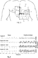
- the Figure 2 illustrates a subcutaneous implantable cardiac defibrillation system 10.
- the Figure 3 illustrates said system 10 in an implanted state.
- the subcutaneous implantable cardiac defibrillation system 10 comprises a casing 12, pulse generator, to which is connected a subcutaneous implantable probe 14.
- the subcutaneous implantable cardiac defibrillation system 10 is able to deliver a defibrillation shock.
- the subcutaneous implantable probe 14 is at least partially flexible and comprises two ends 16, 18: a proximal end 16 which is connected to the housing 12 and a free distal end 18.
- subcutaneous implantable lead 14 includes three sensing electrodes 20, 22, 24 and one defibrillation electrode 26.
- subcutaneous implantable lead 14 could include more than three sensing electrodes.
- Subcutaneous implantable probe 14 also includes conductive wires (which are not visible on the Figure 2 and 3 ) making it possible to electrically connect the electrodes 20, 22, 24 of the probe 14 to electrical contacts (not visible on the Figure 2 and 3 ) at the housing 12 - known per se in the current state of the art.
- At least one of the detection electrodes 20, 22 is formed of a monofilament (not shown) wound around the subcutaneous implantable probe 14.
- at least one detection electrodes 20, 22 is a flexible electrode unlike known conventional probes which are provided with rigid detection rings.
- the detection electrodes 20, 22, 24 can be partially coated with a silicone or polyurethane underlayer.
- the sensing electrodes 20, 22, 24 of the subcutaneous implantable probe 14 allow the detection of electrophysiological signals used to infer the cardiac activity of a patient.
- the detection of electrophysiological activity by the subcutaneous route is however altered by numerous artefacts such as noises of muscular origin or interference with the external environment.
- the probe 14 being of the subcutaneous type, the detection electrodes 20, 22, 24 are not in direct contact with the myocardium.
- the quality of the detection of the electrophysiological signals for a subcutaneous implantable defibrillator thus largely depends on the positioning of the detection electrodes 20, 22, 24.
- the system of subcutaneous implantable cardiac defibrillation device 10 includes specific positioning of sensing electrodes 20, 22, 24. Specifically, as shown in Figure 2 and 3 , a first sensing electrode 20 and a second sensing electrode 22 are positioned between the housing 12 and the defibrillation electrode 26; while a third sensing electrode 24 is placed between the distal end 18 of the lead 14 and the defibrillation electrode 26. The defibrillation electrode 26 is thus positioned between the second sensing electrode 22 and the third detection 24.
- the probe comprises in this order: the first detection electrode 20, the second detection electrode 22, the defibrillation electrode 26 then the third detection electrode 24.
- sensing electrodes 20, 22, 24 The specific positioning of the sensing electrodes 20, 22, 24 will be described in terms of length with reference to the Figure 2 only, representing the probe 14 in an unimplanted, unbent state and aligned along an axis A.
- the first detection electrode 20 and the second detection electrode 22 form a first dipole D1 of length L1.
- the second detection electrode 22 and the third detection electrode 24 form a second dipole D2 of length L2.
- the second dipole D2 can be formed by the third detection electrode 24 and the first detection electrode 20.
- the second dipole D2 can be formed by the housing 12 and one of the three detection electrodes 20 , 22, 24.
- the length L1 of the first dipole D1 is shorter than the length L2 of the second dipole D2.
- the length L1 is between 5 to 50 millimeters, more in particular between 10 and 20 millimeters, while the length L2 is between 50 and 400 millimeters.
- the distance L3 between the first detection electrode 20 and the housing 12 is between 40 and 300 millimeters.
- the subcutaneous implantable cardiac defibrillation system 10 further comprises a controller 28 housed in the housing 12.
- the controller 28 of the system 10 is configured to detect electrical signals recorded simultaneously via the first dipole D1 and the second dipole D2 of the implantable lead under -cutaneous 14.
- the controller 28 is configured to detect the R wave of an electrophysiological signal at the level of the first dipole D1.
- the detection of the R wave via the first dipole could be combined with the detection of electrophysiological signals on a plurality of "second dipoles", i.e. on a plurality of dipoles which are longer than the first dipole, for example: a dipole formed by the second detection electrode 22 and the third detection electrode 24, a dipole formed by the first detection electrode 20 and the third detection electrode 24 and a dipole formed between the housing 12 and the third detection electrode 24.
- the housing 12 can serve as an electrode to form a second dipole with one of the detection electrodes 20, 22, 24.
- the first dipole D1 being shorter than the second dipole D2, the first dipole D1 is less exposed to the risk of oversensing, in particular because it is less likely to record noises of muscular origin.
- the first dipole D1 is positioned during subcutaneous implantation of the system 10 near and above the cardiac notch of the left lung. (in English “left lung cardiac notch”) and ventricles. This particular position of the first dipole D1 makes it possible to detect an electrophysiological signal with an R wave which is more distinctive compared to the P and T waves; the P and T waves detected at this location being minimized compared to the R wave. This advantageous technical effect improving the detection of the R wave via the signals collected from the first dipole D1 is illustrated in Figure 4 .
- the Figure 4 represents several electrophysiological signals of a patient collected in a so-called resting state and during physical exercise, via the D1 dipole and three different D2 dipole configurations.
- the dipole D2 is formed by the second detection electrode 22 and the third detection electrode 24 (see “Dipole D2: 22-24 on the Figure 4 ).
- the dipole D2 is formed by the box 12 and the first detection electrode 20 (see “Dipole D2: 12-20 on the Figure 4 ).
- the dipole D2 is formed by the housing 12 and the third detection electrode 24 (see “Dipole D2: 12-24 on the Figure 4 ).
- the signals collected in the quiescent state demonstrate how the D1 dipole exhibits high, i.e. optimal, R/T and R/P ratios compared to the D2 dipoles.
- the risk of oversensing of the T wave therefore turns out to be lower on the D1 dipole.
- signals collected during exercise show how myopotentials can affect signals.
- the signals collected via the D1 dipole remain much less affected than those of the D2 dipoles. Therefore, it is easier to detect the R wave on the D1 dipole.
- the reason, already mentioned above, comes in particular from the fact that the first dipole D1 being shorter than the second dipole D2, the dipole D1 is less subject to recording noises of muscular origin, liable to alter the signals.
- the subcutaneous implantable probe comprises a fixing means 30.
- the attachment means 30 is positioned between the second sensing electrode 22 and the defibrillation electrode 26.
- the attachment means 30 of the subcutaneous implantable lead 14 is positioned at a distance L4 of between 60 and 300 millimeters from the proximal end 16 of the probe 14 and at a distance L5 of between 50 to 400 millimeters from the distal end 18 of the probe 14.
- L4 and L5 make it possible both to define the positioning of the first dipole D1 and of the second dipole D2 with respect to each other, but also with respect to the muscle mass of the patient when the system 10 is implanted; the housing 12 being usually implanted in the same place in each patient, that is to say on the left side of the patient's chest according to known medical practice and as depicted in the Figure 3 .
- the fixing means 30 also makes it possible to avoid an involuntary displacement of the subcutaneous implantable probe 14, for example generated by a movement of the patient.
- the fixing means 30 thus facilitates maintaining the appropriate positions of the first dipole D1 and of the second dipole D2 relative to each other but also relative to the patient's body.
- the fixing means 30 comprises a groove 32 on the circumference of the subcutaneous implantable probe 14, the width I1 of the groove 32 being dimensioned to accommodate therein a ligature wire 34.
- a practitioner can thus attach the implantable probe under the skin. skin 14 to the tissues, for example the muscle tissues, of a patient by performing a subcutaneous ligation at the level of the fixing means 30.
- the positioning of the fixing means 30 on the subcutaneous implantable probe 14 also makes it possible to define the position of the change in curve of the subcutaneous implantable probe 14. Indeed, when it is implanted subcutaneously, the implantable probe subcutaneous 14 is curved at the level of the fixing means 30 (see Figure 3 ), such that a first portion 36 of probe 14 between proximal end 16 and attachment means 30 is substantially perpendicular to a second portion 38 of probe 14 between distal end 18 and attachment means 30 Thus, the first dipole D1 and the second dipole D2 are preferentially arrangeable so as not to be aligned with each other.
- this essentially perpendicular arrangement between the first portion 36 of the probe and the second portion 38 of the probe 14, produced at the level of the fixing means 30, makes it possible to further improve the quality of the signals detected, in particular because the perpendicularity of the portions 36, 38 of the implanted probe 14 makes it possible to detect signals in a quasi-orthogonal frame.
- the fact that the signals detected via the first dipole and via the second dipole are collected in a quasi-orthogonal manner makes it possible to provide two different perspectives of the electrophysiological signals, from which more information can be extracted and cross-checked; only from one perspective. This information can be used to identify a patient's heart rhythm.
- the subcutaneous implantable cardiac defibrillation system 10 may further comprise an accelerometer or/and a gyroscope configured to sense the position of the patient. Therefore, by allowing the detection of the position of the patient, the interpretation of the electrophysiological signals detected can be further refined, and therefore improved.
- the subcutaneous implantable probe 14 may further comprise a movable insulating means on the first portion 36 of the probe 14 so as to to at least partially cover the first dipole D1 - thus making it possible to shift the position of the dipole D1 on the first portion 36 of the probe 14.
- the specific dimensions L1, L2 L3, L4 and L5 characterizing the subcutaneous implantable cardiac defibrillation system 10 make it possible to improve the quality of the detection of the R wave of the system 10 compared to known subcutaneous implantable cardiac defibrillation systems.
- the detection of the R wave via the first dipole could be combined with the detection of electrophysiological signals on a plurality of "second dipoles", i.e. on a plurality of dipoles which are longer than the first dipole, for example: a dipole formed by the second detection electrode 22 and the third detection electrode 24, a dipole formed by the first detection electrode 20 and the third detection electrode 24 and a dipole formed between the housing 12 and one of the detection electrodes 20, 22, 24.
Landscapes
- Health & Medical Sciences (AREA)
- Cardiology (AREA)
- Radiology & Medical Imaging (AREA)
- Engineering & Computer Science (AREA)
- Biomedical Technology (AREA)
- Nuclear Medicine, Radiotherapy & Molecular Imaging (AREA)
- Life Sciences & Earth Sciences (AREA)
- Animal Behavior & Ethology (AREA)
- General Health & Medical Sciences (AREA)
- Public Health (AREA)
- Veterinary Medicine (AREA)
- Heart & Thoracic Surgery (AREA)
- Electrotherapy Devices (AREA)
- Measurement And Recording Of Electrical Phenomena And Electrical Characteristics Of The Living Body (AREA)
Claims (10)
- Implantierbares subkutanes Herzdefibrillationssystem mit:einem Gehäuse (12); undeiner subkutan implantierbaren Sonde (14) mit zwei Enden (16, 18), die ein mit dem Gehäuse verbundenes proximales Ende (16) und ein als freies Ende (18) gebildetes distales Ende (18) aufweist;wobei die subkutan implantierbare Sonde (14) mindestens eine Defibrillationselektrode (26) und mindestens drei Detektionselektroden (20, 22, 24) aufweist;wobei die erste Detektionselektrode (20) und die zweite Detektionselektrode (22) einen ersten Dipol (D1) bilden;wobei die dritte Detektionselektrode (24) und die erste Detektionselektrode (20) oder die dritte Detektionselektrode (24) und die zweite Detektionselektrode (22), oder das Gehäuse (12) und eine der Detektionselektroden (20, 22, 24) einen zweiten Dipol (D2) bilden;wobei die Defibrillationselektrode (26) zwischen der zweiten Detektionselektrode und der dritten Detektionselektrode (24) angeordnet ist;wobei der erste Dipol (D1) zwischen dem Gehäuse (12) und der Defibrillationselektrode (26) angeordnet ist;wobei die dritte Elektrode (24) zwischen dem freien distalen Ende (18) der Sonde (14) und der Defibrillationselektrode (26) angeordnet ist; undwobei die Länge (L1) des ersten Dipols (D1) kürzer ist als die Länge (L2) des zweiten Dipols (D2).
- Implantierbares subkutanes Herzdefibrillationssystem nach Anspruch 1, ferner umfassend eine Steuerung (28) ausgestaltet zur Erkennung von gleichzeitig über den ersten Dipol (D1) und den zweiten Dipol (D2) der subkutan implantierbaren Sonde (14) erfassten elektrischen Signalen;
wobei die Steuerung (28) zur Erfassung der R-Welle eines elektrischen Signals über den ersten Dipol (D1) ausgestaltet ist. - Implantierbares subkutanes Herzdefibrillationssystem nach einem der vorhergehende Ansprüche, wobei die Länge (L1) des ersten Dipols (D1), also der Abstand zwischen der ersten Detektionselektrode (20) und der zweiten Detektionselektrode (22), zwischen 5 und 50 Millimeter, insbesondere zwischen 10 und 20 Millimeter, beträgt; und
wobei die Länge (L2) des zweiten Dipols (D2), also der Abstand zwischen der dritten Detektionselektrode (24) und der ersten Detektionselektrode (20) oder der dritten Detektionselektrode (24) und der zweiten Detektionselektrode (22) oder dem Gehäuse (12) und einer der Detektionselektroden (20, 22, 24), zwischen 50 und 400 Millimeter beträgt. - Implantierbares subkutanes Herzdefibrillationssystem nach einem der vorhergehende Ansprüche, wobei die subkutan implantierbare Sonde (14) mindestens ein Befestigungsmittel (30) zum Befestigen der subkutan implantierbaren Sonde (14) am Gewebe eines Patienten aufweist.
- Implantierbares subkutanes Herzdefibrillationssystem nach Anspruch 4, wobei das mindestens eine Befestigungsmittel (30) der subkutan implantierbaren Sonde (14) zwischen der zweiten Detektionselektrode (22) und der Defibrillationselektrode (26) angeordnet ist.
- Implantierbares subkutanes Herzdefibrillationssystem nach Anspruch 5, wobei das mindestens eine Befestigungsmittel (30) der subkutan implantierbaren Sonde (14) zwischen 60 und 300 Millimeter von dem proximalen Ende (16) entfernt angeordnet ist; und
das mindestens eine Befestigungsmittel (30) der subkutan implantierbaren Sonde (14) zwischen 50 und 400 Millimeter von dem distalen Ende (18) entfernt angeordnet ist. - Implantierbares subkutanes Herzdefibrillationssystem nach einem der Ansprüche 5 bis 6, wobei das mindestens eine Befestigungsmittel (30) der subkutan implantierbaren Sonde (14) eine Nut (32) am Umfang der subkutan implantierbaren Sonde (14) ist, wobei die Breite der Nut (32) so dimensioniert ist, dass dort ein Ligaturdraht (34) untergebracht werden kann.
- Implantierbares subkutanes Herzdefibrillationssystem nach einem der vorhergehenden Ansprüche, wobei der Abstand (L3) zwischen dem Gehäuse (12) und der ersten Detektionselektrode (20) zwischen 40 und 300 Millimeter beträgt.
- Implantierbares subkutanes Herzdefibrillationssystem nach einem der vorhergehenden Ansprüche, ferner umfassend einen Beschleunigungssensor und/oder ein Gyroskop, ausgestaltet zum Erkennen der Patientenposition.
- Implantierbares subkutanes Herzdefibrillationssystem nach einem der vorhergehenden Ansprüche, wobei der zweite Dipol (D2) durch die dritte Detektionselektrode (24) und die zweite Detektionselektrode (22) gebildet ist.
Applications Claiming Priority (1)
| Application Number | Priority Date | Filing Date | Title |
|---|---|---|---|
| FR1907532 | 2019-07-05 |
Publications (2)
| Publication Number | Publication Date |
|---|---|
| EP3760277A1 EP3760277A1 (de) | 2021-01-06 |
| EP3760277B1 true EP3760277B1 (de) | 2022-09-21 |
Family
ID=67810960
Family Applications (1)
| Application Number | Title | Priority Date | Filing Date |
|---|---|---|---|
| EP20183494.2A Active EP3760277B1 (de) | 2019-07-05 | 2020-07-01 | Subkutan implantierbares kardiales defibrillationssystem |
Country Status (4)
| Country | Link |
|---|---|
| US (2) | US11534616B2 (de) |
| EP (1) | EP3760277B1 (de) |
| JP (1) | JP7096293B2 (de) |
| CN (1) | CN112169175B (de) |
Family Cites Families (23)
| Publication number | Priority date | Publication date | Assignee | Title |
|---|---|---|---|---|
| EP0578748B1 (de) * | 1991-04-05 | 1996-05-01 | Medtronic, Inc. | Erfassungssystem mit subkutanen mehrfachelektroden |
| US5456706A (en) | 1994-01-04 | 1995-10-10 | Ventritex, Inc. | Cardiac defibrillation lead having defibrillation and atrial sensing electrodes |
| DE19800697B4 (de) * | 1998-01-10 | 2009-04-02 | Biotronik Gmbh & Co. Kg | Einzel-Elektrodensonde, insbesondere für implantierbare Defibrillatoren |
| US7392085B2 (en) | 2001-11-21 | 2008-06-24 | Cameron Health, Inc. | Multiple electrode vectors for implantable cardiac treatment devices |
| US7130677B2 (en) | 2002-12-04 | 2006-10-31 | Medtronic, Inc. | Methods and apparatus for discriminating polymorphic tachyarrhythmias from monomorphic tachyarrhythmias facilitating detection of fibrillation |
| WO2004066825A2 (en) | 2003-01-31 | 2004-08-12 | The Board Of Trustees Of The Leland Stanford Junior University | Detection of apex motion for monitoring cardiac dysfunction |
| US20040230230A1 (en) | 2003-04-11 | 2004-11-18 | Lindstrom Curtis Charles | Methods and systems involving subcutaneous electrode positioning relative to a heart |
| US8577455B2 (en) | 2005-01-18 | 2013-11-05 | Medtronic, Inc. | Method and apparatus for arrhythmia detection in a medical device |
| ATE502339T1 (de) | 2008-03-28 | 2011-04-15 | Ela Medical Sa | Aktives medizingerät, das verbesserte mittel zur unterscheidung zwischen tachykardien ventrikulären ursprungs und tachykardien supraventrikulären ursprungs enthält |
| EP2324885B1 (de) | 2009-11-18 | 2018-10-24 | Sorin CRM SAS | Aktives medizinisches gerät mit mitteln zum einfangtesten durch auswertung eines kardialen vektogramms |
| FR2957512A1 (fr) | 2010-03-22 | 2011-09-23 | Sorin Crm Sas | Dispositif medical actif comprenant des moyens de detection et de filtrage d'artefacts par analyse du vectogramme cardiaque |
| EP2742971B1 (de) | 2012-12-14 | 2015-10-21 | Sorin CRM SAS | Aktive implantierbare medizinische Vorrichtung vom Typ Herzschrittmacher mit Nachweistest durch vereinfachte Analyse eines Vektogramms |
| US10556117B2 (en) * | 2013-05-06 | 2020-02-11 | Medtronic, Inc. | Implantable cardioverter-defibrillator (ICD) system including substernal pacing lead |
| US9421360B2 (en) * | 2013-10-17 | 2016-08-23 | Pacesetter, Inc. | Medical device lead assembly having integrated pressure-resisting member |
| US20150306375A1 (en) | 2014-04-25 | 2015-10-29 | Medtronic, Inc. | Implantable extravascular electrical stimulation lead having improved sensing and pacing capability |
| FR3034319A1 (fr) | 2015-04-02 | 2016-10-07 | Sorin Crm Sas | Dispositif medical implantable actif a stimulation biventriculaire, comprenant des moyens de mesure du temps de conduction interventriculaire pour le diagnostic de la decompensation cardiaque. |
| EP3402397B1 (de) | 2016-01-11 | 2022-01-26 | Sorin CRM SAS | Aktive implantierbare medizinische defibrillationsvorrichtung mit verbesserten mitteln zur unterscheidung zwischen externem schall und sondenbruch und zur charakterisierung von tachyarrhythmien |
| US10603483B2 (en) | 2016-04-28 | 2020-03-31 | Medtronic, Inc. | Lead implant fixation mechanism |
| US10391325B2 (en) * | 2016-05-04 | 2019-08-27 | Cardiac Pacemakers, Inc. | Electrode designs in implantable defibrillator systems |
| US10987517B2 (en) | 2017-03-15 | 2021-04-27 | Medtronic, Inc. | Detection of noise signals in cardiac signals |
| US10888697B2 (en) * | 2017-08-18 | 2021-01-12 | Cardiac Pacemakers, Inc. | Fixation mechanism for an implantable lead |
| CN111246909B (zh) | 2017-10-17 | 2024-03-08 | 美敦力公司 | 希氏束和束支起搏调整 |
| US10835741B2 (en) | 2018-03-27 | 2020-11-17 | Pacesetter, Inc. | Screw-in pericardial leads and systems for delivering screw-in pericardial leads |
-
2020
- 2020-07-01 EP EP20183494.2A patent/EP3760277B1/de active Active
- 2020-07-02 US US16/920,118 patent/US11534616B2/en active Active
- 2020-07-03 JP JP2020115478A patent/JP7096293B2/ja active Active
- 2020-07-06 CN CN202010639296.7A patent/CN112169175B/zh active Active
-
2022
- 2022-12-22 US US18/087,325 patent/US12059573B2/en active Active
Also Published As
| Publication number | Publication date |
|---|---|
| US20230131453A1 (en) | 2023-04-27 |
| EP3760277A1 (de) | 2021-01-06 |
| JP2021035490A (ja) | 2021-03-04 |
| CN112169175A (zh) | 2021-01-05 |
| US11534616B2 (en) | 2022-12-27 |
| US20210001137A1 (en) | 2021-01-07 |
| JP7096293B2 (ja) | 2022-07-05 |
| CN112169175B (zh) | 2024-06-07 |
| US12059573B2 (en) | 2024-08-13 |
Similar Documents
| Publication | Publication Date | Title |
|---|---|---|
| US7383091B1 (en) | Medical electrical lead providing far-field signal attenuation | |
| US5476500A (en) | Endocardial lead system with defibrillation electrode fixation | |
| US5683447A (en) | Lead with septal defibrillation and pacing electrodes | |
| US8831705B2 (en) | Devices and method for accelerometer-based characterization of cardiac synchrony and dyssynchrony | |
| US7190993B2 (en) | Implantable medical device having optical fiber for sensing electrical activity | |
| US8118751B2 (en) | Devices and methods for accelerometer-based characterization of cardiac function and identification of LV target pacing zones | |
| US7027852B2 (en) | Lead with distal tip surface electrodes connected in parallel | |
| US7499750B2 (en) | Noise canceling cardiac electrodes | |
| FR2563736A1 (fr) | Catheter intravasculaire unitaire a electrodes multiples et ensemble d'electrodes pour un tel catheter | |
| FR2786701A1 (fr) | Systeme a conducteur electrique medical et a dispositif d'introduction, ensemble conducteur pour un tel systeme et son procede de fabrication | |
| US7660616B1 (en) | Implantable multi-wavelength oximeter sensor | |
| US6647291B1 (en) | Method and apparatus for cardiac defibrillation | |
| US20080183235A1 (en) | Insulative shroud for plate-type electrodes adapted for chronic implantation | |
| US20090005829A1 (en) | Measurement of Cardiac Performance Wtih Movement Sensors and Related Methods | |
| US7949411B1 (en) | Epicardial lead | |
| EP3760277B1 (de) | Subkutan implantierbares kardiales defibrillationssystem | |
| US20170128719A1 (en) | Method for fabricating an implantable lead for applying electrical pulses to tissue of a patient and system for fabrication thereof | |
| CA2525872A1 (en) | Medical system including a novel bipolar pacing pair | |
| EP3760114B1 (de) | Subkutan implantierbare medizinische vorrichtung zur verarbeitung der signale einer subkutan implantierbaren medizinischen vorrichtung | |
| Perzanowski et al. | Implantation of implantable cardioverter-defibrillators from an ileofemoral approach | |
| US9327133B2 (en) | Implantable medical device | |
| EP4058133B1 (de) | Subkutaner herzschrittmacher und herzschrittmacher | |
| EP1118349B1 (de) | Einteilige Sonde für medizinische aktive Vorrichtungen wie implantierbarer Defibrillator/Kardiovertierer | |
| US20080183234A1 (en) | Shroud for plate-type electrodes adapted for chronic implantation surrounding implantable medical devices | |
| FR2661098A1 (fr) | Dispositif d'implantation cardiaque. |
Legal Events
| Date | Code | Title | Description |
|---|---|---|---|
| PUAI | Public reference made under article 153(3) epc to a published international application that has entered the european phase |
Free format text: ORIGINAL CODE: 0009012 |
|
| STAA | Information on the status of an ep patent application or granted ep patent |
Free format text: STATUS: THE APPLICATION HAS BEEN PUBLISHED |
|
| AK | Designated contracting states |
Kind code of ref document: A1 Designated state(s): AL AT BE BG CH CY CZ DE DK EE ES FI FR GB GR HR HU IE IS IT LI LT LU LV MC MK MT NL NO PL PT RO RS SE SI SK SM TR |
|
| AX | Request for extension of the european patent |
Extension state: BA ME |
|
| STAA | Information on the status of an ep patent application or granted ep patent |
Free format text: STATUS: REQUEST FOR EXAMINATION WAS MADE |
|
| 17P | Request for examination filed |
Effective date: 20210706 |
|
| RBV | Designated contracting states (corrected) |
Designated state(s): AL AT BE BG CH CY CZ DE DK EE ES FI FR GB GR HR HU IE IS IT LI LT LU LV MC MK MT NL NO PL PT RO RS SE SI SK SM TR |
|
| GRAP | Despatch of communication of intention to grant a patent |
Free format text: ORIGINAL CODE: EPIDOSNIGR1 |
|
| STAA | Information on the status of an ep patent application or granted ep patent |
Free format text: STATUS: GRANT OF PATENT IS INTENDED |
|
| RIC1 | Information provided on ipc code assigned before grant |
Ipc: A61N 1/39 20060101ALI20220425BHEP Ipc: A61N 1/05 20060101AFI20220425BHEP |
|
| INTG | Intention to grant announced |
Effective date: 20220510 |
|
| GRAS | Grant fee paid |
Free format text: ORIGINAL CODE: EPIDOSNIGR3 |
|
| GRAA | (expected) grant |
Free format text: ORIGINAL CODE: 0009210 |
|
| STAA | Information on the status of an ep patent application or granted ep patent |
Free format text: STATUS: THE PATENT HAS BEEN GRANTED |
|
| AK | Designated contracting states |
Kind code of ref document: B1 Designated state(s): AL AT BE BG CH CY CZ DE DK EE ES FI FR GB GR HR HU IE IS IT LI LT LU LV MC MK MT NL NO PL PT RO RS SE SI SK SM TR |
|
| REG | Reference to a national code |
Ref country code: GB Ref legal event code: FG4D Free format text: NOT ENGLISH |
|
| REG | Reference to a national code |
Ref country code: CH Ref legal event code: EP |
|
| REG | Reference to a national code |
Ref country code: DE Ref legal event code: R096 Ref document number: 602020005214 Country of ref document: DE |
|
| REG | Reference to a national code |
Ref country code: IE Ref legal event code: FG4D Free format text: LANGUAGE OF EP DOCUMENT: FRENCH |
|
| REG | Reference to a national code |
Ref country code: AT Ref legal event code: REF Ref document number: 1519661 Country of ref document: AT Kind code of ref document: T Effective date: 20221015 |
|
| REG | Reference to a national code |
Ref country code: LT Ref legal event code: MG9D |
|
| REG | Reference to a national code |
Ref country code: NL Ref legal event code: MP Effective date: 20220921 |
|
| PG25 | Lapsed in a contracting state [announced via postgrant information from national office to epo] |
Ref country code: SE Free format text: LAPSE BECAUSE OF FAILURE TO SUBMIT A TRANSLATION OF THE DESCRIPTION OR TO PAY THE FEE WITHIN THE PRESCRIBED TIME-LIMIT Effective date: 20220921 Ref country code: RS Free format text: LAPSE BECAUSE OF FAILURE TO SUBMIT A TRANSLATION OF THE DESCRIPTION OR TO PAY THE FEE WITHIN THE PRESCRIBED TIME-LIMIT Effective date: 20220921 Ref country code: NO Free format text: LAPSE BECAUSE OF FAILURE TO SUBMIT A TRANSLATION OF THE DESCRIPTION OR TO PAY THE FEE WITHIN THE PRESCRIBED TIME-LIMIT Effective date: 20221221 Ref country code: LV Free format text: LAPSE BECAUSE OF FAILURE TO SUBMIT A TRANSLATION OF THE DESCRIPTION OR TO PAY THE FEE WITHIN THE PRESCRIBED TIME-LIMIT Effective date: 20220921 Ref country code: LT Free format text: LAPSE BECAUSE OF FAILURE TO SUBMIT A TRANSLATION OF THE DESCRIPTION OR TO PAY THE FEE WITHIN THE PRESCRIBED TIME-LIMIT Effective date: 20220921 Ref country code: FI Free format text: LAPSE BECAUSE OF FAILURE TO SUBMIT A TRANSLATION OF THE DESCRIPTION OR TO PAY THE FEE WITHIN THE PRESCRIBED TIME-LIMIT Effective date: 20220921 |
|
| REG | Reference to a national code |
Ref country code: AT Ref legal event code: MK05 Ref document number: 1519661 Country of ref document: AT Kind code of ref document: T Effective date: 20220921 |
|
| PG25 | Lapsed in a contracting state [announced via postgrant information from national office to epo] |
Ref country code: HR Free format text: LAPSE BECAUSE OF FAILURE TO SUBMIT A TRANSLATION OF THE DESCRIPTION OR TO PAY THE FEE WITHIN THE PRESCRIBED TIME-LIMIT Effective date: 20220921 Ref country code: GR Free format text: LAPSE BECAUSE OF FAILURE TO SUBMIT A TRANSLATION OF THE DESCRIPTION OR TO PAY THE FEE WITHIN THE PRESCRIBED TIME-LIMIT Effective date: 20221222 |
|
| PG25 | Lapsed in a contracting state [announced via postgrant information from national office to epo] |
Ref country code: SM Free format text: LAPSE BECAUSE OF FAILURE TO SUBMIT A TRANSLATION OF THE DESCRIPTION OR TO PAY THE FEE WITHIN THE PRESCRIBED TIME-LIMIT Effective date: 20220921 Ref country code: RO Free format text: LAPSE BECAUSE OF FAILURE TO SUBMIT A TRANSLATION OF THE DESCRIPTION OR TO PAY THE FEE WITHIN THE PRESCRIBED TIME-LIMIT Effective date: 20220921 Ref country code: PT Free format text: LAPSE BECAUSE OF FAILURE TO SUBMIT A TRANSLATION OF THE DESCRIPTION OR TO PAY THE FEE WITHIN THE PRESCRIBED TIME-LIMIT Effective date: 20230123 Ref country code: ES Free format text: LAPSE BECAUSE OF FAILURE TO SUBMIT A TRANSLATION OF THE DESCRIPTION OR TO PAY THE FEE WITHIN THE PRESCRIBED TIME-LIMIT Effective date: 20220921 Ref country code: CZ Free format text: LAPSE BECAUSE OF FAILURE TO SUBMIT A TRANSLATION OF THE DESCRIPTION OR TO PAY THE FEE WITHIN THE PRESCRIBED TIME-LIMIT Effective date: 20220921 Ref country code: AT Free format text: LAPSE BECAUSE OF FAILURE TO SUBMIT A TRANSLATION OF THE DESCRIPTION OR TO PAY THE FEE WITHIN THE PRESCRIBED TIME-LIMIT Effective date: 20220921 |
|
| PG25 | Lapsed in a contracting state [announced via postgrant information from national office to epo] |
Ref country code: SK Free format text: LAPSE BECAUSE OF FAILURE TO SUBMIT A TRANSLATION OF THE DESCRIPTION OR TO PAY THE FEE WITHIN THE PRESCRIBED TIME-LIMIT Effective date: 20220921 Ref country code: PL Free format text: LAPSE BECAUSE OF FAILURE TO SUBMIT A TRANSLATION OF THE DESCRIPTION OR TO PAY THE FEE WITHIN THE PRESCRIBED TIME-LIMIT Effective date: 20220921 Ref country code: IS Free format text: LAPSE BECAUSE OF FAILURE TO SUBMIT A TRANSLATION OF THE DESCRIPTION OR TO PAY THE FEE WITHIN THE PRESCRIBED TIME-LIMIT Effective date: 20230121 Ref country code: EE Free format text: LAPSE BECAUSE OF FAILURE TO SUBMIT A TRANSLATION OF THE DESCRIPTION OR TO PAY THE FEE WITHIN THE PRESCRIBED TIME-LIMIT Effective date: 20220921 |
|
| REG | Reference to a national code |
Ref country code: DE Ref legal event code: R097 Ref document number: 602020005214 Country of ref document: DE |
|
| PG25 | Lapsed in a contracting state [announced via postgrant information from national office to epo] |
Ref country code: NL Free format text: LAPSE BECAUSE OF FAILURE TO SUBMIT A TRANSLATION OF THE DESCRIPTION OR TO PAY THE FEE WITHIN THE PRESCRIBED TIME-LIMIT Effective date: 20220921 Ref country code: AL Free format text: LAPSE BECAUSE OF FAILURE TO SUBMIT A TRANSLATION OF THE DESCRIPTION OR TO PAY THE FEE WITHIN THE PRESCRIBED TIME-LIMIT Effective date: 20220921 |
|
| PLBE | No opposition filed within time limit |
Free format text: ORIGINAL CODE: 0009261 |
|
| STAA | Information on the status of an ep patent application or granted ep patent |
Free format text: STATUS: NO OPPOSITION FILED WITHIN TIME LIMIT |
|
| PG25 | Lapsed in a contracting state [announced via postgrant information from national office to epo] |
Ref country code: DK Free format text: LAPSE BECAUSE OF FAILURE TO SUBMIT A TRANSLATION OF THE DESCRIPTION OR TO PAY THE FEE WITHIN THE PRESCRIBED TIME-LIMIT Effective date: 20220921 |
|
| P01 | Opt-out of the competence of the unified patent court (upc) registered |
Effective date: 20230714 |
|
| 26N | No opposition filed |
Effective date: 20230622 |
|
| PG25 | Lapsed in a contracting state [announced via postgrant information from national office to epo] |
Ref country code: SI Free format text: LAPSE BECAUSE OF FAILURE TO SUBMIT A TRANSLATION OF THE DESCRIPTION OR TO PAY THE FEE WITHIN THE PRESCRIBED TIME-LIMIT Effective date: 20220921 |
|
| PG25 | Lapsed in a contracting state [announced via postgrant information from national office to epo] |
Ref country code: MC Free format text: LAPSE BECAUSE OF FAILURE TO SUBMIT A TRANSLATION OF THE DESCRIPTION OR TO PAY THE FEE WITHIN THE PRESCRIBED TIME-LIMIT Effective date: 20220921 |
|
| PG25 | Lapsed in a contracting state [announced via postgrant information from national office to epo] |
Ref country code: MC Free format text: LAPSE BECAUSE OF FAILURE TO SUBMIT A TRANSLATION OF THE DESCRIPTION OR TO PAY THE FEE WITHIN THE PRESCRIBED TIME-LIMIT Effective date: 20220921 |
|
| REG | Reference to a national code |
Ref country code: CH Ref legal event code: PL |
|
| REG | Reference to a national code |
Ref country code: BE Ref legal event code: MM Effective date: 20230731 |
|
| PG25 | Lapsed in a contracting state [announced via postgrant information from national office to epo] |
Ref country code: LU Free format text: LAPSE BECAUSE OF NON-PAYMENT OF DUE FEES Effective date: 20230701 |
|
| PG25 | Lapsed in a contracting state [announced via postgrant information from national office to epo] |
Ref country code: LU Free format text: LAPSE BECAUSE OF NON-PAYMENT OF DUE FEES Effective date: 20230701 |
|
| REG | Reference to a national code |
Ref country code: IE Ref legal event code: MM4A |
|
| PG25 | Lapsed in a contracting state [announced via postgrant information from national office to epo] |
Ref country code: CH Free format text: LAPSE BECAUSE OF NON-PAYMENT OF DUE FEES Effective date: 20230731 |
|
| PG25 | Lapsed in a contracting state [announced via postgrant information from national office to epo] |
Ref country code: BE Free format text: LAPSE BECAUSE OF NON-PAYMENT OF DUE FEES Effective date: 20230731 |
|
| PG25 | Lapsed in a contracting state [announced via postgrant information from national office to epo] |
Ref country code: IE Free format text: LAPSE BECAUSE OF NON-PAYMENT OF DUE FEES Effective date: 20230701 |
|
| PG25 | Lapsed in a contracting state [announced via postgrant information from national office to epo] |
Ref country code: IE Free format text: LAPSE BECAUSE OF NON-PAYMENT OF DUE FEES Effective date: 20230701 |
|
| PG25 | Lapsed in a contracting state [announced via postgrant information from national office to epo] |
Ref country code: BG Free format text: LAPSE BECAUSE OF FAILURE TO SUBMIT A TRANSLATION OF THE DESCRIPTION OR TO PAY THE FEE WITHIN THE PRESCRIBED TIME-LIMIT Effective date: 20220921 |
|
| PG25 | Lapsed in a contracting state [announced via postgrant information from national office to epo] |
Ref country code: BG Free format text: LAPSE BECAUSE OF FAILURE TO SUBMIT A TRANSLATION OF THE DESCRIPTION OR TO PAY THE FEE WITHIN THE PRESCRIBED TIME-LIMIT Effective date: 20220921 |
|
| PG25 | Lapsed in a contracting state [announced via postgrant information from national office to epo] |
Ref country code: CY Free format text: LAPSE BECAUSE OF FAILURE TO SUBMIT A TRANSLATION OF THE DESCRIPTION OR TO PAY THE FEE WITHIN THE PRESCRIBED TIME-LIMIT; INVALID AB INITIO Effective date: 20200701 |
|
| PG25 | Lapsed in a contracting state [announced via postgrant information from national office to epo] |
Ref country code: HU Free format text: LAPSE BECAUSE OF FAILURE TO SUBMIT A TRANSLATION OF THE DESCRIPTION OR TO PAY THE FEE WITHIN THE PRESCRIBED TIME-LIMIT; INVALID AB INITIO Effective date: 20200701 |
|
| PGFP | Annual fee paid to national office [announced via postgrant information from national office to epo] |
Ref country code: DE Payment date: 20250711 Year of fee payment: 6 |
|
| PGFP | Annual fee paid to national office [announced via postgrant information from national office to epo] |
Ref country code: IT Payment date: 20250708 Year of fee payment: 6 |
|
| PGFP | Annual fee paid to national office [announced via postgrant information from national office to epo] |
Ref country code: GB Payment date: 20250723 Year of fee payment: 6 |
|
| PGFP | Annual fee paid to national office [announced via postgrant information from national office to epo] |
Ref country code: FR Payment date: 20250731 Year of fee payment: 6 |
|
| PG25 | Lapsed in a contracting state [announced via postgrant information from national office to epo] |
Ref country code: TR Free format text: LAPSE BECAUSE OF FAILURE TO SUBMIT A TRANSLATION OF THE DESCRIPTION OR TO PAY THE FEE WITHIN THE PRESCRIBED TIME-LIMIT Effective date: 20220921 |
|
| REG | Reference to a national code |
Ref country code: DE Ref legal event code: R082 Ref document number: 602020005214 Country of ref document: DE Representative=s name: GULDE & PARTNER PATENT- UND RECHTSANWALTSKANZL, DE |