EP3760310B1 - Catalyseur, composition liquide, électrode, électrode catalytique pour réaction électrochimique, pile à combustible et batterie à air - Google Patents
Catalyseur, composition liquide, électrode, électrode catalytique pour réaction électrochimique, pile à combustible et batterie à air Download PDFInfo
- Publication number
- EP3760310B1 EP3760310B1 EP18908102.9A EP18908102A EP3760310B1 EP 3760310 B1 EP3760310 B1 EP 3760310B1 EP 18908102 A EP18908102 A EP 18908102A EP 3760310 B1 EP3760310 B1 EP 3760310B1
- Authority
- EP
- European Patent Office
- Prior art keywords
- electrode
- catalyst
- present
- illustrates
- oxygen reduction
- Prior art date
- Legal status (The legal status is an assumption and is not a legal conclusion. Google has not performed a legal analysis and makes no representation as to the accuracy of the status listed.)
- Active
Links
Images








Classifications
-
- B—PERFORMING OPERATIONS; TRANSPORTING
- B01—PHYSICAL OR CHEMICAL PROCESSES OR APPARATUS IN GENERAL
- B01J—CHEMICAL OR PHYSICAL PROCESSES, e.g. CATALYSIS OR COLLOID CHEMISTRY; THEIR RELEVANT APPARATUS
- B01J31/00—Catalysts comprising hydrides, coordination complexes or organic compounds
- B01J31/16—Catalysts comprising hydrides, coordination complexes or organic compounds containing coordination complexes
- B01J31/18—Catalysts comprising hydrides, coordination complexes or organic compounds containing coordination complexes containing nitrogen, phosphorus, arsenic or antimony as complexing atoms, e.g. in pyridine ligands, or in resonance therewith, e.g. in isocyanide ligands C=N-R or as complexed central atoms
- B01J31/1805—Catalysts comprising hydrides, coordination complexes or organic compounds containing coordination complexes containing nitrogen, phosphorus, arsenic or antimony as complexing atoms, e.g. in pyridine ligands, or in resonance therewith, e.g. in isocyanide ligands C=N-R or as complexed central atoms the ligands containing nitrogen
- B01J31/181—Cyclic ligands, including e.g. non-condensed polycyclic ligands, comprising at least one complexing nitrogen atom as ring member, e.g. pyridine
- B01J31/1825—Ligands comprising condensed ring systems, e.g. acridine, carbazole
- B01J31/183—Ligands comprising condensed ring systems, e.g. acridine, carbazole with more than one complexing nitrogen atom, e.g. phenanthroline
-
- B—PERFORMING OPERATIONS; TRANSPORTING
- B01—PHYSICAL OR CHEMICAL PROCESSES OR APPARATUS IN GENERAL
- B01J—CHEMICAL OR PHYSICAL PROCESSES, e.g. CATALYSIS OR COLLOID CHEMISTRY; THEIR RELEVANT APPARATUS
- B01J31/00—Catalysts comprising hydrides, coordination complexes or organic compounds
- B01J31/16—Catalysts comprising hydrides, coordination complexes or organic compounds containing coordination complexes
- B01J31/22—Organic complexes
-
- H—ELECTRICITY
- H01—ELECTRIC ELEMENTS
- H01M—PROCESSES OR MEANS, e.g. BATTERIES, FOR THE DIRECT CONVERSION OF CHEMICAL ENERGY INTO ELECTRICAL ENERGY
- H01M12/00—Hybrid cells; Manufacture thereof
- H01M12/04—Hybrid cells; Manufacture thereof composed of a half-cell of the fuel-cell type and of a half-cell of the primary-cell type
- H01M12/06—Hybrid cells; Manufacture thereof composed of a half-cell of the fuel-cell type and of a half-cell of the primary-cell type with one metallic and one gaseous electrode
-
- H—ELECTRICITY
- H01—ELECTRIC ELEMENTS
- H01M—PROCESSES OR MEANS, e.g. BATTERIES, FOR THE DIRECT CONVERSION OF CHEMICAL ENERGY INTO ELECTRICAL ENERGY
- H01M12/00—Hybrid cells; Manufacture thereof
- H01M12/08—Hybrid cells; Manufacture thereof composed of a half-cell of a fuel-cell type and a half-cell of the secondary-cell type
-
- H—ELECTRICITY
- H01—ELECTRIC ELEMENTS
- H01M—PROCESSES OR MEANS, e.g. BATTERIES, FOR THE DIRECT CONVERSION OF CHEMICAL ENERGY INTO ELECTRICAL ENERGY
- H01M4/00—Electrodes
- H01M4/86—Inert electrodes with catalytic activity, e.g. for fuel cells
- H01M4/8647—Inert electrodes with catalytic activity, e.g. for fuel cells consisting of more than one material, e.g. consisting of composites
- H01M4/8652—Inert electrodes with catalytic activity, e.g. for fuel cells consisting of more than one material, e.g. consisting of composites as mixture
-
- H—ELECTRICITY
- H01—ELECTRIC ELEMENTS
- H01M—PROCESSES OR MEANS, e.g. BATTERIES, FOR THE DIRECT CONVERSION OF CHEMICAL ENERGY INTO ELECTRICAL ENERGY
- H01M4/00—Electrodes
- H01M4/86—Inert electrodes with catalytic activity, e.g. for fuel cells
- H01M4/90—Selection of catalytic material
- H01M4/9008—Organic or organo-metallic compounds
-
- H—ELECTRICITY
- H01—ELECTRIC ELEMENTS
- H01M—PROCESSES OR MEANS, e.g. BATTERIES, FOR THE DIRECT CONVERSION OF CHEMICAL ENERGY INTO ELECTRICAL ENERGY
- H01M4/00—Electrodes
- H01M4/86—Inert electrodes with catalytic activity, e.g. for fuel cells
- H01M4/90—Selection of catalytic material
- H01M4/9075—Catalytic material supported on carriers, e.g. powder carriers
- H01M4/9083—Catalytic material supported on carriers, e.g. powder carriers on carbon or graphite
-
- H—ELECTRICITY
- H01—ELECTRIC ELEMENTS
- H01M—PROCESSES OR MEANS, e.g. BATTERIES, FOR THE DIRECT CONVERSION OF CHEMICAL ENERGY INTO ELECTRICAL ENERGY
- H01M4/00—Electrodes
- H01M4/86—Inert electrodes with catalytic activity, e.g. for fuel cells
- H01M4/96—Carbon-based electrodes
-
- B—PERFORMING OPERATIONS; TRANSPORTING
- B01—PHYSICAL OR CHEMICAL PROCESSES OR APPARATUS IN GENERAL
- B01J—CHEMICAL OR PHYSICAL PROCESSES, e.g. CATALYSIS OR COLLOID CHEMISTRY; THEIR RELEVANT APPARATUS
- B01J2531/00—Additional information regarding catalytic systems classified in B01J31/00
- B01J2531/80—Complexes comprising metals of Group VIII as the central metal
- B01J2531/84—Metals of the iron group
- B01J2531/842—Iron
-
- H—ELECTRICITY
- H01—ELECTRIC ELEMENTS
- H01M—PROCESSES OR MEANS, e.g. BATTERIES, FOR THE DIRECT CONVERSION OF CHEMICAL ENERGY INTO ELECTRICAL ENERGY
- H01M8/00—Fuel cells; Manufacture thereof
- H01M8/10—Fuel cells with solid electrolytes
- H01M2008/1095—Fuel cells with polymeric electrolytes
-
- H—ELECTRICITY
- H01—ELECTRIC ELEMENTS
- H01M—PROCESSES OR MEANS, e.g. BATTERIES, FOR THE DIRECT CONVERSION OF CHEMICAL ENERGY INTO ELECTRICAL ENERGY
- H01M8/00—Fuel cells; Manufacture thereof
- H01M8/10—Fuel cells with solid electrolytes
-
- Y—GENERAL TAGGING OF NEW TECHNOLOGICAL DEVELOPMENTS; GENERAL TAGGING OF CROSS-SECTIONAL TECHNOLOGIES SPANNING OVER SEVERAL SECTIONS OF THE IPC; TECHNICAL SUBJECTS COVERED BY FORMER USPC CROSS-REFERENCE ART COLLECTIONS [XRACs] AND DIGESTS
- Y02—TECHNOLOGIES OR APPLICATIONS FOR MITIGATION OR ADAPTATION AGAINST CLIMATE CHANGE
- Y02E—REDUCTION OF GREENHOUSE GAS [GHG] EMISSIONS, RELATED TO ENERGY GENERATION, TRANSMISSION OR DISTRIBUTION
- Y02E60/00—Enabling technologies; Technologies with a potential or indirect contribution to GHG emissions mitigation
- Y02E60/30—Hydrogen technology
- Y02E60/50—Fuel cells
Definitions
- the present invention relates to a catalyst, a liquid composition, an electrode, a catalyst electrode for electrochemical reaction, a fuel cell, and an air battery.
- Fuel cells which utilize a reduction reaction of oxygen to produce electrical energy.
- it is common to provide, on the surface of an electrode, a layer of a catalyst for promoting the reduction reaction.
- a platinum-carrying carbon material is known.
- the platinum-carrying carbon material has a superior function of promoting the reduction reaction of oxygen (oxygen reduction catalytic ability).
- Patent Literatures 1 to 4 since platinum is expensive and there is a limited amount of resources therefor, attempts have been made to develop alternative catalysts that are inexpensive and for which there is an abundant amount of resources (Patent Literatures 1 to 4).
- Patent Literature 1 discloses an air electrode catalyst that includes an oxygen reduction catalyst and a cocatalyst, in which the cocatalyst is a carbon material that contains 2% by mass or more of heteroatoms capable of coordination.
- Patent Literature 2 discloses a method for producing an iron phthalocyanine/graphene nanocomposite oxygen reduction catalyst, the method comprising a step of mixing a graphene oxide dispersion with an iron phthalocyanine dispersion to obtain an iron phthalocyanine/graphene oxide composite, and a step of reducing the iron phthalocyanine/graphene oxide composite.
- Patent Literature 3 discloses an electrode catalyst that consists of a catalyst component and a catalyst-carrying material, in which the catalyst component includes a conductive polymer-metal complex that consists of a conductive polymer and a metal ion, the conductive polymer having at least one repeating unit structure selected from the group consisting of indole, isoindole, naphthopyrrole, pyrrolopyridine, benzimidazole, purine, carbazole, phenoxazine, and phenothiazine; and the catalyst-carrying material includes a conductor having a pore structure.
- Patent Literature 4 discloses an electrode for oxygen reduction which includes, as a catalyst component, a cobalt tetrapyrazinoporphyrazine derivative represented by formula (5).
- Patent Literatures 1 to 4 do not make it possible to obtain a catalyst having oxygen reduction catalytic ability surpassing that of a platinum-carrying carbon material.
- iron phthalocyanine having superior conductivity is used to ensure conductivity.
- iron phthalocyanine has low solubility in various solvents and has a restriction on the upper limit of content thereof in a catalyst. Therefore, the low solubility of iron phthalocyanine may limit an improvement in oxygen reduction catalytic ability.
- the manufacturing process thereof requires polymerization of the conductive polymer, and thus it is hard to say that the electrode catalyst is an electrode catalyst which can be easily obtained.
- Patent Literatures 5 and 6 and Non-Patent Literatures 1 and 2 disclose cathode compositions for air batteries or fuel cells, comprising an oxygen reduction catalyst consisting of a metal complex of tetrapyrazinoporphyrazine or tetra-2,3-pyridinoporphyrazine, in admixture with a carbon material as support or co-catalyst.
- Patent Literatures 7 and 8 describe air electrode compositions for fuel cells, comprising a metal complex of a nitrogen-containing macrocyclic ligand, such as phthalocyanine or tetraazaannulene, as oxygen reduction catalyst, in admixture with a carbon material.
- a nitrogen-containing macrocyclic ligand such as phthalocyanine or tetraazaannulene
- An object of the present invention is to provide a catalyst which has oxygen reduction catalytic ability surpassing that of a platinum-carrying carbon material.
- the present inventors have found that applying, to a catalyst, a metal complex having a specific chemical structure and relatively low conductivity is surprisingly effective in achieving the aforementioned object.
- a catalyst which includes a metal complex having a specific chemical structure, has superior oxygen reduction catalytic ability to that of a platinum-carrying carbon material, and thus have completed the present invention.
- the present invention has the following aspects.
- a catalyst can be obtained which has oxygen reduction catalytic ability surpassing that of a platinum-carrying carbon material.
- Heteroatom means an atom other than a carbon atom and a hydrogen atom.
- To used to represent a numerical range means that the range includes numerical values stated before and after the preposition "to” as a lower limit value and an upper limit value.
- the catalyst of the present embodiment (hereinafter referred to as "present catalyst”) includes a metal complex represented by formula (1) and a carbon material.
- X 1 to X 8 each independently represent a hydrogen atom or a halogen atom
- D 1 to D 4 each represent a nitrogen atom or a carbon atom wherein the carbon atom has bound thereto a hydrogen atom or a halogen atom
- M an iron atom
- the bond between the nitrogen atom and M means coordination of the nitrogen atom to M.
- M may be further bound a halogen atom, a hydroxyl group, or a hydrocarbon group having 1 to 8 carbon atoms as a ligand.
- an anionic counterion may be present so that electrical neutrality is maintained.
- the structure of the alkyl group in the alkyloxy group having 1 to 8 carbon atoms may be linear, branched, or cyclic.
- M is an iron atom.
- X 1 to X 8 each independently represent a hydrogen atom or a halogen atom
- D 1' and D 2 to D 4 each represent a nitrogen atom or a carbon atom wherein the carbon atom has bound thereto a hydrogen atom or a halogen atom
- M represents an iron atom
- the metal complex in the present invention may be an isomer as represented by formula (1'). Therefore, it can be said that in formula (1), the position of the nitrogen atom and the position of D 1 are exchangeable with each other in the cyclic structure having D 1 .
- the isomer of the metal complex is not limited to that represented by formula (1').
- formula (1) or formula (1') in at least one selected from the respective cyclic structures containing D 2 to D 4 , respectively, the position of the nitrogen atom may be exchanged with any position of D 2 to D 4 within the same cyclic structure.
- D 1 to D 4 each represent a carbon atom and the carbon atom has bound thereto a hydrogen atom.
- the metal complex is preferably a compound represented by formula (2).
- an electrode containing the present catalyst has even superior conductivity.
- X 1 to X 8 each independently represent a hydrogen atom or a halogen atom, and M represents an iron atom.
- D 1 to D 4 each represent a carbon atom wherein the carbon atom has bound thereto a hydrogen atom
- X 1 to X 8 each represent a hydrogen atom
- the metal complex is preferably a compound represented by formula (3).
- the present catalyst in a case where the metal complex is a compound represented by formula (3), the present catalyst has even superior oxygen reduction catalytic ability.
- M represents an iron atom.
- the metal complex is a compound represented by formula (3)
- the metal complex is iron tetrapyridopolyphyrazine (hereinafter referred to as "FeTPP") represented by formula (4).
- FeTPP iron tetrapyridopolyphyrazine
- the present catalyst has particularly superior oxygen reduction catalytic ability.
- a content of nitrogen atoms in the metal complex is preferably 14% by mass or more, more preferably 16% by mass or more, even more preferably 18% by mass or more, and particularly preferably 19% by mass or more, with respect to 100% by mass of the metal complex.
- the present catalyst has even superior oxidation reduction catalytic ability.
- the content of nitrogen atoms in the metal complex is preferably 40% by mass or less, more preferably 30% by mass or less, even more preferably 28% by mass or less, and particularly preferably 25% by mass or less, with respect to 100% by mass of the metal complex.
- the present catalyst has superior conductivity.
- the content of nitrogen atoms in the metal complex is preferably 14% to 40% by mass, more preferably 16% to 30% by mass, even more preferably 18% to 28% by mass, and particularly preferably 19% to 25% by mass, with respect to 100% by mass of the metal complex.
- a method for producing the iron complex is not particularly limited.
- a method may be exemplified in which a dicyano compound such as pyridine-2,3-dicarbonitrile and an iron atom are heated in an alcohol solvent in the presence of a basic substance.
- a basic substance inorganic bases such as potassium carbonate, sodium carbonate, calcium carbonate, sodium bicarbonate, and sodium acetate; and organic bases such as triethylamine, tributylamine, and diazabicycloundecene may be exemplified.
- the carbon material is carbon nanotube, carbon black or graphene, with the carbon nanotube being preferred.
- SWCNT single-walled carbon nanotube
- DWCNT double-walled carbon nanotube
- MWCNT multi-walled carbon nanotube
- the carbon material may have a functional group such as a hydroxyl group, a carboxyl group, a nitrogen-containing group, a silicon-containing group, a phosphorus-containing group such as a phosphoric group, and a sulfur-containing group such as a sulfonic group.
- the carbon material preferably has a carboxyl group.
- the metal complex is easily adsorbed on the surface of the carbon material, which allows the present catalyst to have superior durability and even superior oxygen reduction catalytic ability.
- the carbon material may have a heteroatom.
- a heteroatom an oxygen atom, a nitrogen atom, a phosphorus atom, a sulfur atom, a silicon atom, and the like may be exemplified.
- the carbon material may contain one heteroatom alone or may contain two or more heteroatoms.
- the carbon material may be oxidized, hydroxylated, nitrided, phosphatized, sulfided, or silicified.
- a content of the carboxyl groups is preferably 20% by mass or less, more preferably 15% by mass or less, and even more preferably 10% by mass or less, with respect to 100% by mass of the carbon material.
- the content of the carboxyl groups is equal to or lower than the upper limit, the production cost of the present catalyst tends to decrease.
- a content of the carboxyl groups is preferably 1% by mass or more, more preferably 5% by mass or more, and even more preferably 8% by mass or more. In a case where the content of the carboxyl groups is equal to or higher than the lower limit, the present catalyst has even superior durability and oxygen reduction catalytic ability.
- a content of the carboxyl groups is preferably 1% to 20% by mass, more preferably 5% to 15% by mass, even more preferably 8% to 15% by mass, and particularly preferably 8% to 10% by mass, with respect to 100% by mass of the carbon material.
- the content of the carboxyl groups can be measured by elemental analysis, X-ray photoelectron spectroscopy, or the like.
- the carbon material is preferably DWCNT with carboxyl groups or MWCNT with carboxyl groups, with MWCNT with carboxyl groups being more preferred.
- a specific surface area of the carbon material is preferably 0.8 m 2 /g or more, more preferably 1.0 m 2 /g or more, even more preferably 1.1 m 2 /g or more, particularly preferably 1.5 m 2 /g or more, and most preferably 2.0 m 2 /g or more.
- the specific surface area is 0.8 m 2 /g or more, agglomeration of the catalyst is easily prevented so that the catalyst has even superior oxygen reduction catalytic ability.
- An upper limit of the specific surface area is not particularly limited. The upper limit of the specific surface area can be set to 2,000 m 2 /g, for example.
- the specific surface area of the carbon material may be, for example, 0.8 to 2,000 m 2 /g, 1.0 to 2,000 m 2 /g, 1.1 to 2,000 m 2 /g, 1.5 to 2,000 m 2 /g, or 2.0 to 2,000 m 2 /g.
- the specific surface area can be measured by a nitrogen adsorption BET method with a specific surface area measuring apparatus.
- An average particle size of the carbon material is not particularly limited.
- the average particle size of the carbon material is preferably, for example, 5 nm to 1,000 ⁇ m.
- the following (A1) to (A3) may be exemplified as methods for adjusting the average particle size of the carbon material so as to be within the aforementioned numerical range.
- the average particle size can be measured with a particle size distribution measuring apparatus, an electron microscope, or the like.
- a proportion of the metal complex is preferably 75% by mass or less, more preferably 50% by mass or less, and even more preferably 30% by mass or less, with respect to a total of 100% by mass of the metal complex and the carbon material. In a case where the proportion of the metal complex is equal to or lower than the upper limit, the present catalyst has superior conductivity.
- the proportion of the metal complex is preferably 0.1% by mass or more, more preferably 0.5% by mass or more, and even more preferably 1% by mass or more, with respect to a total of 100% by mass of the metal complex and the carbon material.
- the proportion of the metal complex is equal to or higher than the lower limit, the present catalyst has even superior oxygen reduction catalytic ability.
- the proportion of the metal complex is preferably 0.1% to 75% by mass, more preferably 0.5% to 50% by mass, and even more preferably 1% to 30% by mass, with respect to a total of 100% by mass of the metal complex and the carbon material.
- the present catalyst can be applied as a material for various industrial products.
- the present catalyst has oxygen reduction catalytic ability. Therefore, the present catalyst can be suitably used for industrial applications in which a reduction reaction of oxygen is utilized.
- the present catalyst in a powdery state can be used, as it is, as a raw material for various industrial products and parts.
- the present catalyst and a platinum-carrying carbon material may be mixed and used.
- a platinum-carrying carbon material for example, Pt/C as described below.
- the present catalyst as described above has improved oxygen reduction catalytic ability because it includes the aforementioned metal complex and carbon material. Thus, oxygen reduction catalytic ability surpassing that of a platinum-carrying carbon material is achieved in the present catalyst.
- the present catalyst exhibits a completely unexpected action effect in that its oxygen reduction catalytic ability is superior to that of a platinum-carrying carbon material.
- the upper limit of content of the metal complex in the present catalyst increases, which allows the catalyst to have even superior oxygen reduction catalytic ability.
- the present catalyst due to higher content of nitrogen atoms in the metal complex, it is easier to increase a content of nitrogen atoms than a case where a compound having a phthalocyanine ring is selected, which allows the catalyst to have even superior oxygen reduction catalytic ability.
- a liquid composition of the present embodiment (hereinafter referred to as "present liquid composition") includes the present catalyst and a liquid medium.
- the present liquid composition may further include optional components other than the present catalyst and the liquid medium.
- the liquid medium may be a compound in which the present catalyst is easily dissolved (that is, in which the present catalyst is highly soluble) or a compound in which the present catalyst is hardly dissolved (that is, in which the present catalyst is poorly soluble).
- the present liquid composition is in the form of a solution.
- the liquid composition is in the form of a dispersion.
- the liquid medium may be an inorganic medium such as water or an organic medium.
- the organic medium examples include alcohol such as methanol, ethanol, propanol, isopropanol (2-propanol), and 1-hexanol; dimethyl sulfoxide; tetrahydrofuran; aprotic polar solvents such as N-methyl pyrrolidone, dimethylformamide, and acetone; and nonpolar solvents such as chloroform, dichloromethane, 1,4-dioxane, benzene, and toluene may be exemplified.
- the liquid medium is not limited to these examples.
- the liquid medium may be used singly, or two or more thereof may be used in combination.
- the present liquid composition may include, as an optional component, a perfluorocarbon material that contains a structural unit based on polytetrafluoroethylene and a perfluoro side chain having a sulfonic acid group.
- a perfluorocarbon material Nafion (product name, manufactured by DuPont) may be exemplified.
- the present liquid composition can be produced by mixing or kneading the present catalyst, the liquid medium and, if necessary, the perfluorocarbon material.
- a mixer At the time of performing the mixing or kneading, ultrasonication, a mixer, a blender, a kneader, a homogenizer, a bead mill, a ball mill, or the like may be used.
- a sieve or the like Before and after the kneading operation, a sieve or the like may be used to adjust an average particle size of the particles.
- the present catalyst, the perfluorocarbon material, and, if necessary, water and alcohol may be mixed and stirred until homogeneity is achieved.
- the present liquid composition can be applied to the surface of various base materials.
- applying the present liquid composition to the surface of a base material and removing the liquid medium makes it possible to provide a layer containing the present catalyst (hereinafter referred to as "layer of the present catalyst") on the surface of various base materials.
- aluminum foil, electrolytic aluminum foil, aluminum mesh (expanded metal), foamed aluminum, punched aluminum, aluminum alloy such as duralumin, copper foil, electrolytic copper foil, copper mesh (expanded metal), foamed copper, punched copper, copper alloy such as brass, brass foil, brass mesh (expanded metal), foamed brass, punched brass, nickel foil, nickel mesh, corrosion-resistant nickel, nickel mesh (expanded metal), punched nickel, foamed nickel, nickel sponge, metal zinc, corrosion-resistant metal zinc, zinc foil, zinc mesh (expanded metal), steel plate, punched steel plate, silver, and the like may be exemplified.
- the base material may be a substrate-like base material, in which examples of the substrate include a silicon substrate; a metal substrate such as gold, iron, stainless steel, copper, aluminum, and lithium; an alloy substrate containing any combination of these metals; an oxide substrate such as indium tin oxide (ITO), indium zinc oxide (IZO), and antimony tin oxide (ATO); and a carbon substrate such as glassy carbon, pyrolytic graphite, and carbon felt.
- the base material is not limited to these examples.
- the present liquid composition as described above can impart, to various base materials, oxygen reduction catalytic ability surpassing that of a platinum-carrying carbon material.
- the present liquid composition can be used, for example, as a coating liquid to be applied to the surface of a base material in a case of producing an electrode as described below.
- the liquid composition may be used, as it is, as a coating liquid, or may be used as a coating liquid after adjusting a content or solid content of the present catalyst.
- the electrode of the present embodiment (hereinafter referred to as "present electrode") includes the present catalyst.
- the present electrode may have a base material that is in contact with a layer of the present catalyst.
- the present electrode may be formed by using the present liquid composition as a coating liquid.
- the present liquid composition is applied to the surface of a conductive base material and components (for example, liquid medium, perfluorocarbon material, and the like) other than the present catalyst are removed.
- components for example, liquid medium, perfluorocarbon material, and the like
- drying by heating may be performed, or drying followed by pressing may be performed.
- the present electrode may have a form in which the layer of the present catalyst is provided on the surface of a conductive base material.
- a thickness of the catalyst layer is not particularly limited, and may be 0.01 to 100 ⁇ m, for example. In a case where the thickness is equal to or higher than the lower limit, the present electrode has superior durability. In a case where the thickness is equal to or lower than the upper limit, the present electrode hardly causes any deterioration in performance.
- the same base materials as those described in the section "Liquid composition” may be exemplified.
- the same base materials as those described in the section "Method for producing electrodes" may be exemplified.
- the layer of the present catalyst may be present on one side or both sides of a base material.
- the present electrode can be used as an electrode of a fuel cell.
- an electrolyte membrane may be placed between a pair of electrodes.
- oxygen reduction reaction represented by formula (6) easily proceeds under an acidic condition
- reduction reaction represented by formula (7) easily proceeds under an alkaline condition.
- the present electrode may be used as an electrode for a fuel cell, in which a substrate having a porous support layer, for example, is used as a base material.
- the present electrode may be used as an electrode that is either a cathode or an anode.
- the porous support layer is a layer that diffuses gas.
- the porous support layer is not particularly limited as long as the layer has electron conductivity, high gas diffusivity, and high corrosion resistance.
- carbon-based porous materials such as carbon paper and carbon cloth, stainless steel foil, and aluminum foil coated with a corrosion-resistant material may be exemplified.
- the present electrode can be suitably applied to an electrode for a power storage device (power generation device) such as a fuel cell or an air battery.
- a power storage device power generation device
- the present electrode as described above Due to having a layer of the present catalyst, the present electrode as described above has improved oxygen reduction catalytic ability.
- the catalyst electrode for electrochemical reaction of the present embodiment (hereinafter referred to as "present catalyst electrode for electrochemical reaction”) includes the present catalyst.
- the present catalyst electrode for electrochemical reaction is an electrode having a function as a catalyst for electrochemical reaction such as predetermined reduction reaction or predetermined oxidation reaction.
- the present catalyst electrode for electrochemical reaction can have a function as a catalyst for the reduction reaction represented by formula (6) or (7).
- the present catalyst electrode for electrochemical reaction may have a base material that is in contact with a layer of the present catalyst.
- the present catalyst electrode for electrochemical reaction may be formed by using the present liquid composition as a coating liquid, similar to the present electrode as described above.
- the present catalyst electrode for electrochemical reaction may have a form in which the layer of the present catalyst is provided on the surface of a conductive base material, similar to the present electrode as described above.
- a conductive base material similar to the present electrode as described above.
- the same base materials as those described in the section "Method for producing electrodes" are mentioned.
- the layer of the present catalyst may be present on one side or both sides of a base material.
- the present catalyst electrode for electrochemical reaction may be produced by vacuum deposition or the like.
- the present catalyst electrode for electrochemical reaction as described above has improved oxygen reduction catalytic ability.
- present fuel cell has the present electrode as described above.
- the present fuel cell may further have a second electrode, an electrolyte, and a separator.
- the present electrode may be a cathode or an anode.
- the present electrode is preferably a cathode, and more preferably an oxygen electrode.
- the oxygen electrode means an electrode to which an oxygen-containing gas (such as air) is supplied.
- the second electrode is an electrode used in combination with the present electrode.
- the second electrode is an anode; and in a case where the present electrode is an anode, the second electrode is a cathode.
- the second electrode single metals such as aluminum and zinc, and oxides of these metals may be exemplified.
- the second electrode is not limited to these examples.
- the electrolyte is preferably an aqueous electrolytic solution.
- aqueous electrolytic solution alkaline aqueous solutions such as potassium hydroxide aqueous solution and sodium hydroxide aqueous solution; and acidic aqueous solutions such as sulfuric acid aqueous solution may be exemplified.
- the electrolyte may be used singly, or two or more thereof may be used in combination.
- the electrolyte is not limited to these examples, and may be an inorganic solid electrolyte.
- the separator is a member that separates the present electrode and the second electrode, and holds the electrolyte to secure ion conductivity between the present electrode and the second electrode.
- microporous polymers such as polyethylene, polypropylene, polytetrafluoroethylene, polyvinylidene fluoride, cellulose, cellulose acetate, hydroxyalkyl cellulose, carboxymethyl cellulose, polyvinyl alcohol, cellophane, polystyrene, polyacrylonitrile, polyacrylamide, polyvinyl chloride, polyamide, vinylon, and poly(meth)acrylic acid, gel compounds, ion exchange membranes, cyclized polymers, poly(meth)acrylate-containing polymers, sulfonate-containing polymers, quaternary ammonium salt-containing polymers, quaternary phosphonium salt-containing polymers, and the like may be exemplified.
- the separator is not limited to these examples.
- the present fuel cell may be a primary cell or a secondary cell.
- molten carbonate fuel cell MCFC
- PAFC phosphoric acid fuel cell
- SOFC solid oxide fuel cell
- PEFC polymer electrolyte fuel cell
- the form of the present fuel cell is not limited to these examples, and is preferably PEFC.
- the present fuel cell as described above has the present electrode, and thus oxygen reduction characteristics of oxygen reduction reaction are improved in the electrode. As a result, the present fuel cell has superior energy conversion efficiency.
- An air battery of the present embodiment (hereinafter referred to as "present air battery”) has the present electrode as described above.
- the present air battery it is preferable to apply the present electrode as an oxygen electrode.
- the present air battery may further have a fuel electrode, an electrolyte, and a separator.
- the fuel electrode is an electrode used in combination with the present electrode.
- the fuel electrode those similar to the specific examples described in the section "Second electrode” may be exemplified.
- the present air battery as described above has the present electrode, and thus oxygen reduction characteristics of oxygen reduction reaction are improved in the electrode. As a result, the present air battery has superior energy conversion efficiency.
- an aqueous dispersion of the product and an aqueous solution of ⁇ -cyano-4-hydroxycinnamic acid were mixed at a mass ratio of 1:4, the mixture was dried at room temperature, and then measurement was performed using a matrix-assisted laser desorption/ionization time-of-flight mass spectrometer (REFLEX III, manufactured by Bruker Daltonics).
- REFLEX III a matrix-assisted laser desorption/ionization time-of-flight mass spectrometer
- UV-vis measurement was performed using an ultraviolet-visible spectrophotometer (V-670, manufactured by JASCO) in a state in which each sample is dispersed in methanol or DMSO.
- V-670 ultraviolet-visible spectrophotometer
- the EDX spectral analysis was performed using an atomic resolution analytical electron microscope (JEM-ARM200F, manufactured by JEOL).
- the TG-DTA measurement was performed by a thermal analyzer (Thermo plus EvoII, manufactured by Rigaku Corporation) under a nitrogen atmosphere at a condition with a temperature elevation rate of 5°C/min.
- the LSV curve was obtained with CompactStat (NH-COMPACT, manufactured by Ivium Technologies) while using oxygen-saturated 0.1 M KOH as an electrolytic solution, under a condition of a sweep rate of 5 mV/s, in a sweep range of which the lower limit is -0.8 V and the upper limit is 0.2V.
- a rotation speed of the rotating disk was set to 2,400 rpm, Pt wire was used as a counter electrode, and Ag/AgCl was used as a reference electrode.
- the number of reaction electrons was calculated based on a K-L plot. Current densities of the ring electrode and fthe disk electrode were calculated from the LSV measurement, and the number of reaction electrons was calculated based on RRDE.
- Example 1 The metal complex of Example 1 was dissolved in DMSO, and measurement by MALDI-TOF mass spectrometry and measurement by UV-vis were performed.
- Fig. 1 illustrates a spectrum diagram showing the measurement results obtained by MALDI-TOF mass spectrometry in Example 1.
- FeTPP has a mass average molecular weight of 572.07.
- peaks were observed at positions corresponding to mass average molecular weights of 572.099 and 586.943. From this result, it was suggested that the metal complex of Example 1 may have a methyl group bound to an iron atom that is a central metal.
- Fig. 2 illustrates a spectrum diagram showing the measurement results obtained by UV-vis in Example 1.
- a Q band unique to a phthalocyanine analog was observed near 600 nm, and a Soret band was observed near 300 to 400 nm. Accordingly, it was identified that FeTPP can be synthesized.
- a metal complex (that is, FeTPP) was obtained in the same manner as in Example 1.
- the obtained FeTPP was dissolved in 0.5 mL of DMSO.
- the resulting solution and 10 mg of MWCNT with carboxyl groups (diameter: 9.5 nm, length: 1.5 ⁇ m) were stirred with a homogenizer for 10 minutes.
- the stirred solution was washed with DMSO three times and then further washed with methanol three times, to obtain a methanol dispersion containing the catalyst of Example 2 (methanol dispersion of Example 2).
- a methanol dispersion containing the catalyst of Example 3 (methanol dispersion of Example 3) was obtained in the same manner as in Example 2, except that 10 mg of CB is used as the carbon material.
- a methanol dispersion containing the catalyst of Example 4 (methanol dispersion of Example 4) was obtained in the same manner as in Example 2, except that 10 mg of GO is used as the carbon material.
- a methanol dispersion containing the catalyst of Example 5 (methanol dispersion of Example 5) was obtained in the same manner as in Example 2, except that a compound represented by formula (9) is used as the metal complex.
- Fig. 3 illustrates a schematic diagram showing the catalyst of Example 2.
- the carboxyl group of MWCNT is negatively charged, it is highly possible that FeTPP is adsorbed on the surface of MWCNT.
- Fig. 4 illustrates a spectrum diagram showing the measurement results obtained by UV-vis in Example 2.
- Example 1 shows a spectrum of the solution obtained by dissolving FeTPP of Example 1 in DMSO.
- Example 2 shows a spectrum of the methanol dispersion of Example 2.
- the line indicated by "MWCNT with carboxyl groups" in Fig. 4 shows a spectrum of the solution obtained by dissolving MWCNT in DMSO.
- Fig. 5 illustrates a spectrum diagram showing the results obtained by infrared spectroscopic analysis in Example 2.
- Example 1 shows a spectrum of the solution obtained by dissolving FeTPP of Example 1 in DMSO.
- Example 2 shows a spectrum of the methanol dispersion of Example 2.
- the line indicated by "MWCNT with carboxyl groups" in Fig. 5 shows a spectrum of the solution obtained by dissolving MWCNT with carboxyl groups in DMSO.
- Fig. 6 illustrates a graph showing the results obtained by laser Raman spectroscopic analysis in Example 2.
- Figs. 7 and 8 illustrate enlarged views of Fig. 6 .
- Example 2 shows spectra of the methanol dispersion of Example 2.
- the peak intensity ratio R was calculated using equation (8).
- the peak intensity ratio R of CNT/FeTPP was 1.6
- the peak intensity ratio R of CNT/FeTPP calcination was 1.5
- the peak intensity ratio R of CNT was 1.5.
- Fig. 9 illustrates a TEM-observed image of the methanol dispersion of Example 2.
- Fig. 10 illustrates an enlarged view of Fig. 9 .
- Fig. 11 illustrates a TEM-observed image of MWCNT.
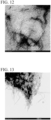
- Fig. 11 is a comparison target of Fig. 9 .
- Fig. 12 illustrates an enlarged view of Fig. 11 .
- Fig. 13 illustrates a TEM-observed image of a calcination product of the methanol dispersion of Example 2.
- Fig. 14 illustrates an enlarged view of Fig. 13 .
- a diameter of the catalyst of Example 2 in the methanol dispersion was calculated, and the diameter was 14.3 ⁇ 1.8 nm.
- a diameter of MWCNT was measured, and the diameter was 8.7 ⁇ 1.1 nm. From this result, it was identified that a catalyst containing FeTPP and MWCNT is obtained.
- a layer containing FeTPP FeTPP layer
- the FeTPP layer has a thickness of about 2.8 nm.
- Fig. 15 illustrates a TEM-observed image of the methanol dispersion of Example 2.
- Fig. 16 illustrates a TEM-observed image of MWCNT. Comparison between Fig. 15 and Fig. 16 suggested that in the catalyst of Example 2, the FeTPP layer is provided on the surface of MWCNT.
- Fig. 17 illustrates a STEM-observed image of the methanol dispersion of Example 2.
- Fig. 18 illustrates a STEM-observed image of MWCNT.
- the FeTPP layer could not be observed in the catalyst of Example 2.
- Fig. 19 illustrates a TEM-observed image of the methanol dispersion of Example 3.
- Fig. 20 illustrates an enlarged view of Fig. 19 .
- Fig. 21 illustrates a TEM-observed image of CB.
- Fig. 22 illustrates an enlarged view of Fig. 21 .
- Fig. 23 illustrates a TEM-observed image of a calcination product of the methanol dispersion of Example 3.
- Fig. 24 illustrates an enlarged view of Fig. 23 .
- Fig. 25 illustrates a TEM-observed image of the methanol dispersion of Example 4.
- Fig. 26 illustrates an enlarged view of Fig. 25 .
- Fig. 27 illustrates a TEM-observed image of GO.
- Fig. 28 illustrates an enlarged view of Fig. 27 .
- Fig. 29 illustrates a TEM-observed image of a calcination product of the methanol dispersion in Example 4.
- Fig. 30 illustrates an enlarged view of Fig. 29 .
- Fig. 31 illustrates a spectrum diagram showing the measurement results obtained by EDX spectral analysis in the catalyst of Example 2.
- Fig. 32 illustrates an elemental mapping image based on the measurement results shown in Fig. 31 .
- Fig. 33 illustrates a spectrum diagram showing measurement results obtained by EDX spectral analysis in MWCNT.
- Fig. 34 illustrates an elemental mapping image based on the measurement results shown in Fig. 33 .
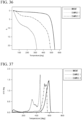
- Fig. 35 illustrates a graph showing the measurement results obtained by TG-DTA.
- Fig. 35 an amount of mass reduction is plotted on the vertical axis.
- Fig. 36 illustrates an enlarged view of Fig. 35 .
- Fig. 37 illustrates a graph showing the measurement results obtained by TG-DTA.
- a temperature derivative of an amount of mass reduction is plotted on the vertical axis.
- Fig. 38 illustrates an enlarged view of Fig. 37 .
- Example 2 2 mg of the catalyst of Example 2 and 1 mg of Milli-Q water were kneaded with an ultrasonic stirrer and applied to a glassy carbon electrode. To the glassy carbon electrode was further applied 5 ⁇ L of 0.5% (by mass) Nafion aqueous solution, to obtain the electrode of Example 2.
- the electrode of Example 3 was obtained in the same manner as for the electrode of Example 2, except that the catalyst of Example 3 is used in place of the catalyst of Example 2.
- the electrode of Example 5 was obtained in the same manner as for the electrode of Example 2, except that the catalyst of Example 5 is used in place of the catalyst of Example 2.
- the electrode of Comparative Example 1 was obtained in the same manner as for the electrode of Example 2, except that 2 mg of the calcination product of the catalyst of Example 2 is used in place of the catalyst of Example 2.
- the Pt/C electrode was obtained in the same manner as for the electrode of Example 2, except that Pt/C is used in place of the catalyst of Example 2.
- the CNT electrode was obtained in the same manner as for the electrode of Example 2, except that MWCNT is used in place of the catalyst of Example 2.
- Fig. 39 illustrates a diagram showing a comparison of LSV curves obtained by using, as a working electrode, each of the electrode of Example 2, the electrode of Comparative Example 1, the Pt/C electrode, and the CNT electrode. As illustrated in Fig. 39 , it was found that the electrode of Example 2 exhibits a saturation current value equivalent to that of the Pt/C electrode.
- Fig. 40 illustrates an enlarged view of Fig. 39 .
- the electric potential at which oxygen reduction reaction starts was higher than that of the Pt/C electrode.
- the average number of reaction electron was 3.4 electrons for the electrode of Example 2, 3.0 electrons for the electrode of Comparative Example 1, 3.7 electrons for the Pt/C electrode, and 3.2 electrons for the CNT electrode. From these results, it was found that the electrode of Example 2 has oxygen reduction catalytic ability surpassing that of the Pt/C electrode.
- the calcination product of the catalyst of Example 2 is considered to have lost the chemical structure of FeTPP, which was originally possessed by the catalyst of Example 2, due to an effect of calcination. Therefore, it is considered that the electrode of Comparative Example 1 did not exhibit the oxygen reduction catalytic ability surpassing that of the Pt/C electrode.
- Fig. 41 illustrates a graph showing the results obtained by calculating the number of reaction electrons based on a K-L plot in the electrode of Example 2.
- Fig. 42 illustrates a graph showing the results obtained by calculating the number of reaction electrons based on RRDE in the electrode of Example 2.
- Fig. 43 illustrates a graph showing the results obtained by calculating the number of reaction electrons based on a K-L plot in the CNT electrode.
- Fig. 44 illustrates a graph showing the results obtained by calculating the number of reaction electrons based on RRDE in the CNT electrode.
- Fig. 45 illustrates a graph showing a comparison of results obtained by calculating the number of reaction electrons based on a K-L plot, in the electrode of Example 2 and the CNT electrode.
- Fig. 46 illustrates a graph showing a comparison of results obtained by calculating the number of reaction electrons based on RRDE, in the electrode of Example 2 and the CNT electrode.
- Methanol crossover was evaluated at a condition in which 3.0 M methanol is added to 0.1 M KOH electrolyte and a rotation speed is set to 2,400 rpm.
- Fig. 47 illustrates a graph showing the results obtained by evaluating methanol crossover in the electrode of Example 2.
- the curve indicated by "electrode of Example 2 without methanol treatment” shows an LSV curve measured without addition of methanol to the electrolytic solution
- the curve indicated by "electrode of Example 2 with methanol treatment” shows an LSV curve measured with addition of 3.0 M methanol to the electrolytic solution.
- Fig. 48 illustrates a graph showing the results obtained by evaluating methanol crossover in the CNT electrode.
- the curve indicated by "CNT electrode without methanol treatment” shows an LSV curve measured without addition of methanol to the electrolytic solution
- the curve indicated by "CNT electrode with methanol treatment” shows an LSV curve measured with addition of 3.0 M methanol to the electrolytic solution.
- Example 2 The electrode of Example 2 was energized for 7,000 seconds by application of 0.7 V and changes with time in current value were measured with CompactStat (MH-COMPACT, manufactured by Ivium) while using 1.0 M KOH electrolyte as an electrolytic solution, Pt as a counter electrode, and Ag/AgCl as a reference electrode. A relative current (%) was plotted on the vertical axis, in which the current value immediately after the start of energization is set as 100%.
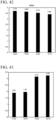
- Fig. 49 illustrates a graph showing the results obtained by evaluating durability in the electrode of Example 2.
- the electrode of Example 2 had a relative current of about 100% even after 7,000 seconds had elapsed from the start of energization, suggesting that the electrode has superior durability.
- Fig. 50 illustrates a diagram showing a comparison of LSV curves obtained by using, as a working electrode, each of the electrode of Example 3 and the Pt/C electrode.
- the carbon material is CB.
- the electrode of Example 3 exhibits a higher saturation current value than the Pt/C electrode.
- the electric potential at which oxygen reduction reaction starts was higher than that of the Pt/C electrode. From these results, it was found that the electrode of Example 3 has oxygen reduction catalytic ability surpassing that of the Pt/C electrode.
- Fig. 51 illustrates a diagram showing a comparison of LSV curves obtained by using, as a working electrode, each of the electrode of Example 5 and the Pt/C electrode.
- the structure of the metal complex is represented by formula (9).
- the electrode of Example 5 exhibits a saturation current value equivalent to that of the Pt/C electrode.
- the electric potential at which oxygen reduction reaction starts was higher than that of the Pt/C electrode. From the above, it was found that the electrode of Example 5 has oxygen reduction catalytic ability surpassing that of the Pt/C electrode.
- the electrode of Example 3 has a higher saturation current value than that of the electrode of Example 5.
- the electric potential at which oxygen reduction reaction starts was higher than that of the electrode of Example 5. From the above, it is considered that as an electrode of a fuel cell or an air battery, the electrode of Example 3 has higher performance than the electrode of Example 5.
Landscapes
- Chemical & Material Sciences (AREA)
- Chemical Kinetics & Catalysis (AREA)
- General Chemical & Material Sciences (AREA)
- Electrochemistry (AREA)
- Engineering & Computer Science (AREA)
- Materials Engineering (AREA)
- Manufacturing & Machinery (AREA)
- Inorganic Chemistry (AREA)
- Organic Chemistry (AREA)
- Composite Materials (AREA)
- Catalysts (AREA)
- Inert Electrodes (AREA)
- Fuel Cell (AREA)
- Hybrid Cells (AREA)
Claims (9)
- Catalyseur de réduction d'oxygène comprenant :un complexe métallique représenté par la formule (1) ; etun matériau carboné,
 dans lequel, dans la formule (1), X1 à X8 représentent chacun indépendamment un atome d'hydrogène ou un atome d'halogène, D1 à D4 représentent chacun un atome d'azote ou un atome de carbone, dans lequel l'atome de carbone est lié à un atome d'hydrogène ou à un atome d'halogène, et M représente un atome de fer ;dans lequel le matériau carboné est un nanotube de carbone, un noir de carbone ou un graphène.
 - Catalyseur de réduction d'oxygène selon la revendication 1,
dans lequel une proportion du complexe métallique est de 75 % en masse ou moins par rapport à un total de 100 % en masse du complexe métallique et du matériau carboné. - Catalyseur de réduction d'oxygène selon l'une des revendications 1 ou 2,
dans lequel le matériau carboné contient un groupe carboxyle, et une teneur en groupes carboxyle est de 20 % en masse ou moins par rapport à 100 % en masse du matériau carboné. - Catalyseur de réduction d'oxygène selon l'une quelconque des revendications 1 à 3,
dans lequel le complexe métallique est un composé représenté par la formule (2),
- Composition liquide comprenant :le catalyseur de réduction d'oxygène selon l'une quelconque des revendications 1 à 4 ; etun milieu liquide.
- Électrode comprenant :
le catalyseur de réduction d'oxygène selon l'une quelconque des revendications 1 à 4. - Électrode de catalyseur pour réaction électrochimique, comprenant :
le catalyseur de réduction d'oxygène selon l'une quelconque des revendications 1 à 4. - Pile à combustible comprenant :
l'électrode selon la revendication 6. - Batterie à air, comprenant :
l'électrode selon la revendication 6.
Applications Claiming Priority (2)
| Application Number | Priority Date | Filing Date | Title |
|---|---|---|---|
| JP2018037521 | 2018-03-02 | ||
| PCT/JP2018/047829 WO2019167407A1 (fr) | 2018-03-02 | 2018-12-26 | Catalyseur, composition liquide, électrode, électrode catalytique pour réaction électrochimique, pile à combustible et batterie à air |
Publications (4)
| Publication Number | Publication Date |
|---|---|
| EP3760310A1 EP3760310A1 (fr) | 2021-01-06 |
| EP3760310A4 EP3760310A4 (fr) | 2021-12-01 |
| EP3760310C0 EP3760310C0 (fr) | 2025-05-21 |
| EP3760310B1 true EP3760310B1 (fr) | 2025-05-21 |
Family
ID=67804931
Family Applications (1)
| Application Number | Title | Priority Date | Filing Date |
|---|---|---|---|
| EP18908102.9A Active EP3760310B1 (fr) | 2018-03-02 | 2018-12-26 | Catalyseur, composition liquide, électrode, électrode catalytique pour réaction électrochimique, pile à combustible et batterie à air |
Country Status (7)
| Country | Link |
|---|---|
| US (1) | US11772084B2 (fr) |
| EP (1) | EP3760310B1 (fr) |
| JP (2) | JP7460152B2 (fr) |
| KR (2) | KR20200138250A (fr) |
| CN (1) | CN112041061A (fr) |
| ES (1) | ES3031838T3 (fr) |
| WO (1) | WO2019167407A1 (fr) |
Families Citing this family (10)
| Publication number | Priority date | Publication date | Assignee | Title |
|---|---|---|---|---|
| JP7082342B2 (ja) * | 2018-03-30 | 2022-06-08 | 学校法人関西学院 | 燃料電池の空気側電極用触媒 |
| KR102720978B1 (ko) | 2019-09-05 | 2024-10-22 | 아줄 에너지 인크. | 촉매의 제조 방법, 촉매, 조성물의 제조 방법, 조성물, 전극, 전극의 제조 방법, 연료 전지, 금속 공기 전지 |
| JP7418753B2 (ja) * | 2020-03-05 | 2024-01-22 | 大日精化工業株式会社 | 酸化物系電極触媒及び固体高分子形燃料電池 |
| JP7687651B2 (ja) * | 2020-12-24 | 2025-06-03 | AZUL Energy株式会社 | 酸素還元用触媒及びその選定方法、酸素還元用触媒を含む液状組成物又は電極、電極を備える空気電池又は燃料電池 |
| JP7761915B2 (ja) * | 2020-12-24 | 2025-10-29 | AZUL Energy株式会社 | 金属錯体又はその付加体、金属錯体又はその付加体を含む触媒及びその製造方法、触媒を含む液状組成物又は電極、電極を備える空気電池又は燃料電池 |
| WO2022224990A1 (fr) * | 2021-04-21 | 2022-10-27 | AZUL Energy株式会社 | Condensateur, et matériau composite de condensateur et son procédé de fabrication |
| JP7731099B2 (ja) * | 2021-07-14 | 2025-08-29 | 一般財団法人電力中央研究所 | コンクリートデバイスおよび電子機器 |
| JP7592341B2 (ja) * | 2021-12-22 | 2024-12-02 | AZUL Energy株式会社 | 電気自動車又はドローン装置の給電システム |
| KR20230162032A (ko) * | 2021-12-28 | 2023-11-28 | 아줄 에너지 인크. | 촉매 및 그 제조 방법, 촉매를 포함하는 금속 공기 2차 전지용의 전극 또는 수전해 시스템용의 전극 및 전극을 포함하는 금속 공기 2차 전지 또는 수전해 시스템 |
| JP2024117064A (ja) * | 2023-02-16 | 2024-08-28 | 株式会社豊田中央研究所 | 電気化学反応器、カソード触媒の製造方法及び分散液 |
Family Cites Families (13)
| Publication number | Priority date | Publication date | Assignee | Title |
|---|---|---|---|---|
| JPS58186169A (ja) * | 1982-04-22 | 1983-10-31 | Pentel Kk | 空気極 |
| GB9109751D0 (en) * | 1991-05-04 | 1991-06-26 | Johnson Matthey Plc | Improved catalyst material |
| CN101147286A (zh) * | 2005-08-25 | 2008-03-19 | 松下电器产业株式会社 | 氧还原用电极 |
| EP2498516B1 (fr) | 2007-03-23 | 2014-02-26 | Panasonic Corporation | Dispositif de station de base de communication radio et procédé d'agencement de canal de contrôle |
| JP5251009B2 (ja) | 2007-06-14 | 2013-07-31 | 東洋紡株式会社 | 電極触媒 |
| CN101417242B (zh) * | 2008-11-27 | 2010-08-11 | 上海交通大学 | 一种复合型的非贵金属氧还原催化剂 |
| US20110244357A1 (en) * | 2009-08-27 | 2011-10-06 | Swift Enterprises, Ltd. | Electrocatalyst Composition And Fuel Cell Containing Same |
| JP5212533B2 (ja) | 2011-11-15 | 2013-06-19 | 新日鐵住金株式会社 | 継目無オーステナイト系耐熱合金管 |
| US10199657B2 (en) | 2012-04-11 | 2019-02-05 | Ionic Materials, Inc. | Alkaline metal-air battery cathode |
| JP6047742B2 (ja) | 2012-10-31 | 2016-12-21 | 国立大学法人 熊本大学 | 鉄フタロシアニン/グラフェンナノ複合体、鉄フタロシアニン/グラフェンナノ複合体担持電極及びこれらの製造方法 |
| WO2015139660A1 (fr) * | 2014-03-21 | 2015-09-24 | 中国科学院苏州纳米技术与纳米仿生研究所 | Microsphères poreuses à base de nanotubes de carbone, leur procédé de préparation et leur utilisation, matériau composite carboné à squelette métallique à base de lithium, son procédé de préparation, électrode négative et batterie |
| JP2016085925A (ja) * | 2014-10-28 | 2016-05-19 | 株式会社日本触媒 | 空気極用触媒 |
| JP6741943B2 (ja) | 2016-08-31 | 2020-08-19 | 富士通株式会社 | 半導体装置及びその製造方法 |
-
2018
- 2018-12-26 US US16/976,283 patent/US11772084B2/en active Active
- 2018-12-26 EP EP18908102.9A patent/EP3760310B1/fr active Active
- 2018-12-26 CN CN201880091934.7A patent/CN112041061A/zh active Pending
- 2018-12-26 JP JP2020502828A patent/JP7460152B2/ja active Active
- 2018-12-26 WO PCT/JP2018/047829 patent/WO2019167407A1/fr not_active Ceased
- 2018-12-26 KR KR1020207028212A patent/KR20200138250A/ko not_active Ceased
- 2018-12-26 ES ES18908102T patent/ES3031838T3/es active Active
- 2018-12-26 KR KR1020247001260A patent/KR20240011249A/ko not_active Ceased
-
2023
- 2023-02-24 JP JP2023027571A patent/JP7572074B2/ja active Active
Also Published As
| Publication number | Publication date |
|---|---|
| JPWO2019167407A1 (ja) | 2021-03-11 |
| EP3760310A1 (fr) | 2021-01-06 |
| EP3760310C0 (fr) | 2025-05-21 |
| WO2019167407A1 (fr) | 2019-09-06 |
| US11772084B2 (en) | 2023-10-03 |
| KR20240011249A (ko) | 2024-01-25 |
| KR20200138250A (ko) | 2020-12-09 |
| ES3031838T3 (en) | 2025-07-11 |
| CN112041061A (zh) | 2020-12-04 |
| US20210308659A1 (en) | 2021-10-07 |
| JP7572074B2 (ja) | 2024-10-23 |
| EP3760310A4 (fr) | 2021-12-01 |
| JP2023071802A (ja) | 2023-05-23 |
| JP7460152B2 (ja) | 2024-04-02 |
Similar Documents
| Publication | Publication Date | Title |
|---|---|---|
| US11772084B2 (en) | Catalyst, liquid composition, electrode, catalyst electrode for electrochemical reaction, fuel cell, and air battery | |
| Kim et al. | Effect of surface oxygen functionalization of carbon support on the activity and durability of Pt/C catalysts for the oxygen reduction reaction | |
| EP3787080A1 (fr) | Catalyseur de pile à combustible, ensemble membrane-électrode pour pile à combustible et pile à combustible équipée de celui-ci | |
| EP1570539A2 (fr) | Electrode de pile a combustible comprenant des nanotubes de carbone | |
| JP2005527957A (ja) | プロトン伝導性炭素性材料 | |
| WO2015088025A1 (fr) | Matiere carbonee de support pour pile a combustible a polymere solide, matiere carbonee de support de particules de catalyseur metallique et procede de fabrication desdites matieres | |
| CN115715230B (zh) | 氧还原用催化剂及其选定方法、包含氧还原用催化剂的液态组合物或电极、具备电极的空气电池或燃料电池 | |
| KR101624641B1 (ko) | 연료전지용 전극 촉매, 그 제조방법, 및 이 전극 촉매를 이용한 막 전극 접합체와 연료전지 | |
| WO2016177951A1 (fr) | Catalyseur supporte par des nanotubes de carbone et par du graphene, et son procédé de préparation | |
| CA2646994C (fr) | Catalyseur d'electrode pour cellule electrochimique, son procede de fabrication, pile electrochimique, cellule individuelle pour pile a combustible et pile a combustible | |
| Zurowski et al. | Activation of carbon-supported platinum nanoparticles by zeolite-type cesium salts of polyoxometallates of molybdenum and tungsten towards more efficient electrocatalytic oxidation of methanol and ethanol | |
| Kireeti et al. | Surface tailored single walled carbon nanotubes as catalyst support for direct methanol fuel cell | |
| US12394803B2 (en) | Production method of catalyst, catalyst, production method of composition, composition, electrode, manufacturing method of electrode, fuel cell, metal-air battery | |
| JP7825828B2 (ja) | 新規触媒組成物並びに窒素含有基を有する炭素材料 | |
| JP2025534469A (ja) | ナノ触媒を含むリチウム硫黄電池用カソード | |
| JPWO2009051111A1 (ja) | 燃料電池用担持触媒及び燃料電池 | |
| Johnston et al. | Se-modified Ru nanoparticles as ORR catalysts–Part 1: Synthesis and analysis by RRDE and in PEFCs | |
| JP2006209999A (ja) | 固体高分子形燃料電池用電極およびその製造方法 | |
| JP5948452B2 (ja) | 燃料電池用担持触媒の製造方法 | |
| JP2006252938A (ja) | 固体高分子形燃料電池用電極およびその製造方法 | |
| JP5759695B2 (ja) | 燃料電池用担持触媒の製造方法 | |
| WO2025028613A1 (fr) | Matériau d'électrode, électrode, ensemble membrane-électrode et pile à combustible de type polymère solide | |
| HK40128815A (zh) | 用於氢燃料电池的钌基催化剂 | |
| JP2010146828A (ja) | 固体高分子形燃料電池用触媒粉末およびその製造方法 |
Legal Events
| Date | Code | Title | Description |
|---|---|---|---|
| STAA | Information on the status of an ep patent application or granted ep patent |
Free format text: STATUS: THE INTERNATIONAL PUBLICATION HAS BEEN MADE |
|
| PUAI | Public reference made under article 153(3) epc to a published international application that has entered the european phase |
Free format text: ORIGINAL CODE: 0009012 |
|
| STAA | Information on the status of an ep patent application or granted ep patent |
Free format text: STATUS: REQUEST FOR EXAMINATION WAS MADE |
|
| 17P | Request for examination filed |
Effective date: 20200924 |
|
| AK | Designated contracting states |
Kind code of ref document: A1 Designated state(s): AL AT BE BG CH CY CZ DE DK EE ES FI FR GB GR HR HU IE IS IT LI LT LU LV MC MK MT NL NO PL PT RO RS SE SI SK SM TR |
|
| AX | Request for extension of the european patent |
Extension state: BA ME |
|
| DAV | Request for validation of the european patent (deleted) | ||
| DAX | Request for extension of the european patent (deleted) | ||
| A4 | Supplementary search report drawn up and despatched |
Effective date: 20211103 |
|
| RIC1 | Information provided on ipc code assigned before grant |
Ipc: H01M 12/08 20060101ALN20211027BHEP Ipc: H01M 8/1018 20160101ALN20211027BHEP Ipc: H01M 8/10 20160101ALN20211027BHEP Ipc: H01M 4/86 20060101ALI20211027BHEP Ipc: H01M 4/96 20060101ALI20211027BHEP Ipc: H01M 4/90 20060101AFI20211027BHEP |
|
| REG | Reference to a national code |
Ref country code: DE Ref legal event code: R079 Free format text: PREVIOUS MAIN CLASS: B01J0031220000 Ipc: H01M0004900000 Ref document number: 602018082212 Country of ref document: DE |
|
| GRAP | Despatch of communication of intention to grant a patent |
Free format text: ORIGINAL CODE: EPIDOSNIGR1 |
|
| STAA | Information on the status of an ep patent application or granted ep patent |
Free format text: STATUS: GRANT OF PATENT IS INTENDED |
|
| RIC1 | Information provided on ipc code assigned before grant |
Ipc: H01M 12/08 20060101ALN20241128BHEP Ipc: H01M 8/1018 20160101ALN20241128BHEP Ipc: H01M 8/10 20160101ALN20241128BHEP Ipc: H01M 4/86 20060101ALI20241128BHEP Ipc: H01M 4/96 20060101ALI20241128BHEP Ipc: H01M 4/90 20060101AFI20241128BHEP |
|
| INTG | Intention to grant announced |
Effective date: 20241211 |
|
| RIN1 | Information on inventor provided before grant (corrected) |
Inventor name: NOZAKI, KOHEI Inventor name: HIRAI, YUTARO Inventor name: ABE, HIROYA Inventor name: KUMATANI, AKICHIKA Inventor name: MATSUE, TOMOKAZU Inventor name: YABU, HIROSHI |
|
| GRAS | Grant fee paid |
Free format text: ORIGINAL CODE: EPIDOSNIGR3 |
|
| GRAA | (expected) grant |
Free format text: ORIGINAL CODE: 0009210 |
|
| STAA | Information on the status of an ep patent application or granted ep patent |
Free format text: STATUS: THE PATENT HAS BEEN GRANTED |
|
| AK | Designated contracting states |
Kind code of ref document: B1 Designated state(s): AL AT BE BG CH CY CZ DE DK EE ES FI FR GB GR HR HU IE IS IT LI LT LU LV MC MK MT NL NO PL PT RO RS SE SI SK SM TR |
|
| REG | Reference to a national code |
Ref country code: GB Ref legal event code: FG4D |
|
| REG | Reference to a national code |
Ref country code: CH Ref legal event code: EP |
|
| REG | Reference to a national code |
Ref country code: DE Ref legal event code: R096 Ref document number: 602018082212 Country of ref document: DE |
|
| REG | Reference to a national code |
Ref country code: IE Ref legal event code: FG4D |
|
| U01 | Request for unitary effect filed |
Effective date: 20250605 |
|
| REG | Reference to a national code |
Ref country code: ES Ref legal event code: FG2A Ref document number: 3031838 Country of ref document: ES Kind code of ref document: T3 Effective date: 20250711 |
|
| U07 | Unitary effect registered |
Designated state(s): AT BE BG DE DK EE FI FR IT LT LU LV MT NL PT RO SE SI Effective date: 20250613 |
|
| PG25 | Lapsed in a contracting state [announced via postgrant information from national office to epo] |
Ref country code: NO Free format text: LAPSE BECAUSE OF FAILURE TO SUBMIT A TRANSLATION OF THE DESCRIPTION OR TO PAY THE FEE WITHIN THE PRESCRIBED TIME-LIMIT Effective date: 20250821 Ref country code: GR Free format text: LAPSE BECAUSE OF FAILURE TO SUBMIT A TRANSLATION OF THE DESCRIPTION OR TO PAY THE FEE WITHIN THE PRESCRIBED TIME-LIMIT Effective date: 20250822 |
|
| PG25 | Lapsed in a contracting state [announced via postgrant information from national office to epo] |
Ref country code: PL Free format text: LAPSE BECAUSE OF FAILURE TO SUBMIT A TRANSLATION OF THE DESCRIPTION OR TO PAY THE FEE WITHIN THE PRESCRIBED TIME-LIMIT Effective date: 20250521 |
|
| PG25 | Lapsed in a contracting state [announced via postgrant information from national office to epo] |
Ref country code: HR Free format text: LAPSE BECAUSE OF FAILURE TO SUBMIT A TRANSLATION OF THE DESCRIPTION OR TO PAY THE FEE WITHIN THE PRESCRIBED TIME-LIMIT Effective date: 20250521 |
|
| PG25 | Lapsed in a contracting state [announced via postgrant information from national office to epo] |
Ref country code: RS Free format text: LAPSE BECAUSE OF FAILURE TO SUBMIT A TRANSLATION OF THE DESCRIPTION OR TO PAY THE FEE WITHIN THE PRESCRIBED TIME-LIMIT Effective date: 20250821 |
|
| PG25 | Lapsed in a contracting state [announced via postgrant information from national office to epo] |
Ref country code: IS Free format text: LAPSE BECAUSE OF FAILURE TO SUBMIT A TRANSLATION OF THE DESCRIPTION OR TO PAY THE FEE WITHIN THE PRESCRIBED TIME-LIMIT Effective date: 20250921 |
|
| PG25 | Lapsed in a contracting state [announced via postgrant information from national office to epo] |
Ref country code: SM Free format text: LAPSE BECAUSE OF FAILURE TO SUBMIT A TRANSLATION OF THE DESCRIPTION OR TO PAY THE FEE WITHIN THE PRESCRIBED TIME-LIMIT Effective date: 20250521 |
|
| PG25 | Lapsed in a contracting state [announced via postgrant information from national office to epo] |
Ref country code: CZ Free format text: LAPSE BECAUSE OF FAILURE TO SUBMIT A TRANSLATION OF THE DESCRIPTION OR TO PAY THE FEE WITHIN THE PRESCRIBED TIME-LIMIT Effective date: 20250521 |
|
| U20 | Renewal fee for the european patent with unitary effect paid |
Year of fee payment: 8 Effective date: 20251215 |
|
| PG25 | Lapsed in a contracting state [announced via postgrant information from national office to epo] |
Ref country code: SK Free format text: LAPSE BECAUSE OF FAILURE TO SUBMIT A TRANSLATION OF THE DESCRIPTION OR TO PAY THE FEE WITHIN THE PRESCRIBED TIME-LIMIT Effective date: 20250521 |
|
| PLBE | No opposition filed within time limit |
Free format text: ORIGINAL CODE: 0009261 |
|
| STAA | Information on the status of an ep patent application or granted ep patent |
Free format text: STATUS: NO OPPOSITION FILED WITHIN TIME LIMIT |
|
| REG | Reference to a national code |
Ref country code: CH Ref legal event code: L10 Free format text: ST27 STATUS EVENT CODE: U-0-0-L10-L00 (AS PROVIDED BY THE NATIONAL OFFICE) Effective date: 20260402 |
|
| PGFP | Annual fee paid to national office [announced via postgrant information from national office to epo] |
Ref country code: ES Payment date: 20260119 Year of fee payment: 8 |
|
| 26N | No opposition filed |
Effective date: 20260224 |