EP3760321B1 - Multimaterialwandlergehäuse - Google Patents
Multimaterialwandlergehäuse Download PDFInfo
- Publication number
- EP3760321B1 EP3760321B1 EP20183829.9A EP20183829A EP3760321B1 EP 3760321 B1 EP3760321 B1 EP 3760321B1 EP 20183829 A EP20183829 A EP 20183829A EP 3760321 B1 EP3760321 B1 EP 3760321B1
- Authority
- EP
- European Patent Office
- Prior art keywords
- transducer
- tube
- enclosure
- transducer assembly
- plastic material
- Prior art date
- Legal status (The legal status is an assumption and is not a legal conclusion. Google has not performed a legal analysis and makes no representation as to the accuracy of the status listed.)
- Active
Links
Images





Classifications
-
- G—PHYSICS
- G01—MEASURING; TESTING
- G01N—INVESTIGATING OR ANALYSING MATERIALS BY DETERMINING THEIR CHEMICAL OR PHYSICAL PROPERTIES
- G01N29/00—Investigating or analysing materials by the use of ultrasonic, sonic or infrasonic waves; Visualisation of the interior of objects by transmitting ultrasonic or sonic waves through the object
- G01N29/22—Details, e.g. general constructional or apparatus details
- G01N29/32—Arrangements for suppressing undesired influences, e.g. temperature or pressure variations, compensating for signal noise
-
- G—PHYSICS
- G01—MEASURING; TESTING
- G01F—MEASURING VOLUME, VOLUME FLOW, MASS FLOW OR LIQUID LEVEL; METERING BY VOLUME
- G01F1/00—Measuring the volume flow or mass flow of fluid or fluent solid material wherein the fluid passes through a meter in a continuous flow
- G01F1/66—Measuring the volume flow or mass flow of fluid or fluent solid material wherein the fluid passes through a meter in a continuous flow by measuring frequency, phase shift or propagation time of electromagnetic or other waves, e.g. using ultrasonic flowmeters
- G01F1/662—Constructional details
-
- G—PHYSICS
- G01—MEASURING; TESTING
- G01F—MEASURING VOLUME, VOLUME FLOW, MASS FLOW OR LIQUID LEVEL; METERING BY VOLUME
- G01F15/00—Details of, or accessories for, apparatus of groups G01F1/00 - G01F13/00 insofar as such details or appliances are not adapted to particular types of such apparatus
- G01F15/14—Casings, e.g. of special material
-
- G—PHYSICS
- G01—MEASURING; TESTING
- G01N—INVESTIGATING OR ANALYSING MATERIALS BY DETERMINING THEIR CHEMICAL OR PHYSICAL PROPERTIES
- G01N29/00—Investigating or analysing materials by the use of ultrasonic, sonic or infrasonic waves; Visualisation of the interior of objects by transmitting ultrasonic or sonic waves through the object
- G01N29/22—Details, e.g. general constructional or apparatus details
- G01N29/222—Constructional or flow details for analysing fluids
-
- G—PHYSICS
- G01—MEASURING; TESTING
- G01N—INVESTIGATING OR ANALYSING MATERIALS BY DETERMINING THEIR CHEMICAL OR PHYSICAL PROPERTIES
- G01N29/00—Investigating or analysing materials by the use of ultrasonic, sonic or infrasonic waves; Visualisation of the interior of objects by transmitting ultrasonic or sonic waves through the object
- G01N29/22—Details, e.g. general constructional or apparatus details
- G01N29/223—Supports, positioning or alignment in fixed situation
-
- G—PHYSICS
- G01—MEASURING; TESTING
- G01N—INVESTIGATING OR ANALYSING MATERIALS BY DETERMINING THEIR CHEMICAL OR PHYSICAL PROPERTIES
- G01N29/00—Investigating or analysing materials by the use of ultrasonic, sonic or infrasonic waves; Visualisation of the interior of objects by transmitting ultrasonic or sonic waves through the object
- G01N29/22—Details, e.g. general constructional or apparatus details
- G01N29/24—Probes
- G01N29/2437—Piezoelectric probes
-
- B—PERFORMING OPERATIONS; TRANSPORTING
- B06—GENERATING OR TRANSMITTING MECHANICAL VIBRATIONS IN GENERAL
- B06B—METHODS OR APPARATUS FOR GENERATING OR TRANSMITTING MECHANICAL VIBRATIONS OF INFRASONIC, SONIC, OR ULTRASONIC FREQUENCY, e.g. FOR PERFORMING MECHANICAL WORK IN GENERAL
- B06B1/00—Methods or apparatus for generating mechanical vibrations of infrasonic, sonic, or ultrasonic frequency
- B06B1/02—Methods or apparatus for generating mechanical vibrations of infrasonic, sonic, or ultrasonic frequency making use of electrical energy
- B06B1/06—Methods or apparatus for generating mechanical vibrations of infrasonic, sonic, or ultrasonic frequency making use of electrical energy operating with piezoelectric effect or with electrostriction
- B06B1/0644—Methods or apparatus for generating mechanical vibrations of infrasonic, sonic, or ultrasonic frequency making use of electrical energy operating with piezoelectric effect or with electrostriction using a single piezoelectric element
-
- Y—GENERAL TAGGING OF NEW TECHNOLOGICAL DEVELOPMENTS; GENERAL TAGGING OF CROSS-SECTIONAL TECHNOLOGIES SPANNING OVER SEVERAL SECTIONS OF THE IPC; TECHNICAL SUBJECTS COVERED BY FORMER USPC CROSS-REFERENCE ART COLLECTIONS [XRACs] AND DIGESTS
- Y04—INFORMATION OR COMMUNICATION TECHNOLOGIES HAVING AN IMPACT ON OTHER TECHNOLOGY AREAS
- Y04S—SYSTEMS INTEGRATING TECHNOLOGIES RELATED TO POWER NETWORK OPERATION, COMMUNICATION OR INFORMATION TECHNOLOGIES FOR IMPROVING THE ELECTRICAL POWER GENERATION, TRANSMISSION, DISTRIBUTION, MANAGEMENT OR USAGE, i.e. SMART GRIDS
- Y04S20/00—Management or operation of end-user stationary applications or the last stages of power distribution; Controlling, monitoring or operating thereof
- Y04S20/30—Smart metering, e.g. specially adapted for remote reading
Definitions
- Utility meters may include ultrasonic transducers and other components.
- the design requirements for such meters include issues of quality, accuracy, power consumption, and cost.
- improved techniques for manufacturing and assembly of a transducer and a printed circuit board (PCB) of the utility meter would increase quality and reduce costs.
- storage and transport periods of the transducer lifecycle may include relative humidity 50 to 100 percent.
- JP2016008880A describes an ultrasonic flowmeter which aims to stabilize its shape by suppressing thermal expansion of a measurement conduit line made of fluororesin.
- An ultrasonic flowmeter 100 in a time difference system is provided comprising ultrasonic transceivers 140, 150 on an upstream side and a downstream side of a measurement conduit line 110 made of fluororesin where fluid F to be measured flows.
- US2019008580A1 describes an intravascular catheter for nerve activity ablation and/or sensing includes one or more needles advanced through supported guide tubes (needle guiding elements) which expand to contact the interior surface of the wall of the renal artery or other vessel of a human body allowing the needles to be advanced though the vessel wall into the extra-luminal tissue including the media, adventitia and periadvential space.
- the catheter also includes structures which provide radial and lateral support to the guide tubes so that the guide tubes open uniformly and maintain their position against the interior surface of the vessel wall as the sharpened needles are advanced to penetrate into the vessel wall.
- US2009173167A1 describes a Coriolis flowmeter including an oscillator for oscillating a fluid pipe that forms a flow path for allowing a measurement fluid to flow; first and second detectors that are disposed to be spaced apart from each other along the flow path of the fluid pipe so as to detect a state of oscillation of the fluid pipe; and a calculator for calculating a mass flow rate of the measurement fluid that passes through the flow path of the fluid pipe on the basis of a relative amount of the states of oscillation that are detected by the first and second detectors.
- the fluid pipe includes an inner pipe made of a fluororesin whose inner circumferential surface is in contact with the flow path, and an outer pipe having fibers that are arranged in order to surround an outer circumferential surface of the inner pipe and a resin that is cured in a state of close adhesion between the fibers arranged in order, and having an elastic modulus larger than that of the inner pipe.
- US 2008/0276724 A1 describes systems and methods of a transducer having a plastic matching layer.
- Transducers comprising a housing (having a proximal end, a distal end and an internal volume, the housing configured to couple to a spoolpiece of an ultrasonic meter), a plastic matching layer that has an external surface and an internal surface (the plastic matching layer seals to and occludes the distal end of the housing), and a transducer element abutting the internal surface of the plastic matching layer.
- transducer assembly according to claim 1.
- Optional features are set out in the dependent claims.
- FIGS. 1 through 11 show example transducer assemblies that may be converted from a moisture-proof state suitable for storage and/or transport to an operational state that allows a desiccant to remove moisture.
- the disclosure describes techniques for providing an ultrasonic transducer (usable in some examples in a water meter, gas meter, or other device) having features and techniques for maintaining the transducer in a waterproof state and a non-waterproof state.
- ambient relative humidity can vary widely, and may reach levels that are too high.
- Such humidity may degrade electronic components such as an ultrasonic transducer (e.g., a piezo device).
- the high humidity may damage the glue that couples the piezo device to the housing. Accordingly, example features and techniques hold the transducer in a waterproof state during these times.
- the transducer Upon installation in a water meter or other device, the transducer is transitioned to a non-waterproof state, to thereby allow water to be exhausted from the transducer.
- water may enter the transducer in small quantities.
- a desiccant may be used to lower the humidity in the environment of the transducer. Because the transducer is in the non-waterproof state, any small quantities of water that entered the transducer are removed from the transducer and absorbed by the desiccant.
- a tube may provide a channel within the transducer. At one end of the channel is an area near the piezo device and associated glue attaching it to the housing and/or enclosure.
- an end of the tube protrudes from the enclosure of the transducer.
- a frangible end of the tube can be broken off.
- the transducer Prior to breaking the end of the tube, the transducer is in the waterproof state, and the internal components such as the piezo device and glue attaching it to the enclosure are protected from humidity. The state is considered waterproof at least in part because the environmental conditions during storage and transportation are not nearly as wet as they are in the operational mode, and the transducer is essentially waterproof.
- the transducer After breaking off the end of the tube, the transducer is in the non-waterproof state. In an operative state, some water may enter the transducer's enclosure. Accordingly, by transitioning to the non-waterproof state, water can be removed.
- any moisture entering the transducer such as from condensation on a pipe to which the transducer is attached, may exit through the open end of the tube, where the moisture is absorbed by the desiccant. Accordingly, before and after installation and operation, the piezo unit, glue and other transducer components are held and maintained in a sufficiently low humidity environment.
- the disclosure describes techniques for providing a plug to protect and guide wiring during storage, transportation, and the manufacturing process.
- the techniques provide for an improved connection between the transducer and an electronic printed circuit board (PCB) and allow for a fully automated manufacturing process.
- a plastic plug is configured for insertion into an enclosure of a transducer.
- Two wires e.g., electrical cables
- an assembly process attaches the wires of the transducer to a PCB.
- the disclosure describes advantages of a transducer assembly having a bi-material enclosure.
- a plastic housing with mechanical reinforcements e.g., 40% glass fiber
- Transducer assemblies using a plastic sleeve having little or no reinforcing materials may provide less variations in signal transmission between assemblies than such assemblies having reinforcing materials.
- Removing reinforcing materials from the plastic sleeve obviates concern over variations in fiber content and/or alignment.
- Removing reinforcing material from the plastic sleeve also obviates concern over the quality of fiber coatings, which may become exposed after wear and create a moisture-entry path.
- the bi-material transducer enclosure provides resistance to pressure and consistency between transducer assemblies.
- FIGS. 1 through 11 show examples by which example transducers may be converted from a waterproof state suitable for storage and/or transport to an operational state that allows water molecules to be exhausted through an open tube and to be absorbed by a desiccant to remove moisture from the transducers.
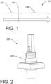
- FIG. 1 shows an example of a lifecycle timeline 100 of a transducer for a metering device.
- the first period 102 in the lifecycle e.g., zero to eighteen months
- the transducer may be subject to high humidity (e.g., 50% to 100% relative humidity).
- Humidity may damage electronic components, the piezo device, and/or glue attaching the piezo device to a housing or enclosure of the transducer. Accordingly, the transducer must be protected from the humidity, and an enclosure of the transducer must be in a waterproof mode, state and/or condition.
- the transducer and an associated water or gas metering device may have a 15- to 20-year lifespan 106.
- any humidity entering the enclosure must be exhausted from the enclosure.
- Water may enter the enclosure of the ultrasonic transducer due to that enclosure's connection and/or proximity to water or gas pipes. Accordingly, an opening in the enclosure is used to exhaust and/or transfer any moisture and humidity from the enclosure. Such water may be transferred to a desiccant within the water or gas meter. This process keeps the humidity within the metering device quite low (e.g., less than 10% relative humidity). Because the transducer must be able to exhaust any humidity to the desiccant, it is in a non-waterproof mode, state and/or condition during the operating period 106.
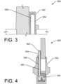
- FIG. 2 shows an example transducer assembly 200, having an enclosure 202.
- the transducer assembly 200 may include an ultrasonic sensor (e.g., a piezo device), wiring, glue, layers of epoxy or plastic, backing, a humidity-exhausting tube, etc.
- the transducer assembly 200 is shown in a waterproof state to protect it from a high humidity environment.
- the waterproof state obviates the need to pack the transducer in desiccant during the storage, warehousing, transportation and/or inventorying phases of its lifecycle.
- the waterproof state also reduces failure rates that would accompany the failure of such desiccant during wet environments, poor warehousing techniques, etc.
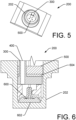
- FIG. 3 shows a portion of the transducer assembly 200.
- a plastic tube 300 connects the internal areas of the transducer assembly (not shown) to the atmosphere outside the enclosure of the transducer (e.g., the interior of the metering device).
- the tube 300 shows a closed end-cap 302 of the plastic tube 300, which results in a waterproof state or mode of the transducer assembly 200.
- the waterproof state or more is associated with the storage, transportation and/or warehousing stages of the lifecycle of the transducer, before it is installed on a water pipe and/or in a meter.
- a thin or frangible region 304 of the tube 300 allows the closed end-cap 302 of the tube to be easily broken off.
- an open channel of the tube provides ventilation between an interior of the transducer assembly 200 and atmosphere outside the enclosure portion of the transducer assembly.
- the transducer assembly 200 is in the non-waterproof state or mode.
- the non-waterproof state or mode allows water that essentially cannot be stopped from very slowly entering the enclosure of the transducer assembly 200 to be exhausted (through tube 300) at a similar rate, thereby keeping the relative humidity within the enclosure of the transducer assembly at a low level.
- the non-waterproof state or mode is associated with the 15 to 20-year operational life span of the transducer assembly 200.
- FIG. 4 shows an example transducer assembly 200 in cross-section.
- the transducer assembly 200 of the transducer is configured to protect an ultrasonic transducer and other components both in storage and after installation in a metering device.
- the tube 300 defines a channel 400 that provides ventilation (if the open state, with end-cap 302 removed) between the atmosphere and the region 402 within the enclosure 202 of the transducer assembly near the ultrasonic device.
- the tube 300 has an end-cap 302 which may be broken off at a frangible or weakened location 304. Accordingly, when the endcap 302 is present, the channel 400 of the tube 300 is sealed, and the enclosure is in the waterproof state for warehousing, transportation and/or inventory.
- the channel 400 of the tube 300 provides ventilation from the inside of the enclosure 202 to the atmosphere outside the transducer assembly, and the enclosure is in the non-waterproof state or mode.
- the non-waterproof mode allows small amounts of water that cannot be conveniently stopped from entering the enclosure 202 of the transducer to be exhausted out the channel 400 of the tube 300 and into a desiccant over an approximately 20-year operating lifetime of the transducer.
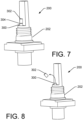
- FIG. 5 shows a portion of the enclosure 202 of a transducer assembly 200.
- the tube 300 of the enclosure 20 of the transducer extends through a layer 500, which provides structural support and water-proofing.
- the layer 500 is made of epoxy resin. Accordingly, the tube 300 passing through the resin layer 500 is held in place in a waterproof manner.
- FIG. 6 shows portions of the example enclosure 202 of a transducer assembly 200, and an arrangement of components within the enclosure, including an ultrasonic (e.g., piezo) device 600 and glue 602 sealing the piezo device to a base portion of the enclosure.
- the channel 400 of the tube 300 is configured to transfer humidity from the area of the piezo device to the atmosphere (if the end-cap has been removed).
- the view shows a layer of epoxy resin 500 and a layer of silicon glue 604.
- FIG. 7 shows an example enclosure 202 for an ultrasonic transducer assembly 200 with a closed channel, suitable for warehousing, shipping, storage and pre-installation situations.
- the tube 300 defining a channel is sealed by the end-cap 302.
- the frangible region 304 has not be broken. Accordingly, the enclosure 202 is in the waterproof condition, phase and/or mode of the transducer lifecycle.
- FIG. 8 shows an example process by which the tube 300 and associated internal channel (channel 400, seen in FIG. 4 ) is opened.
- the process involves breaking the frangible region 304 (shown in FIG. 7 ) to thereby remove the end-cap 302.
- the process transitions the enclosure 202 for a transducer assembly 200 from the waterproof configuration used for shipping, storage and/or pre-installation situations to a non-waterproof configuration used during operation. Because the waterproof condition may not be truly waterproof in an operating environment, the transducer is kept drier by having the tube 300 open, to thereby allow water to be removed from the enclosure 202 of the transducer assembly 200 and absorbed by the desiccant within an enclosure of a metering device.
- FIG. 9 shows an example enclosure 202 for ultrasonic transducer assembly 200 with an open channel 400 of the tube 300 channel 406, suitable for operational situations.
- the endcap has been removed and is not shown.
- the tube 300 is open because the frangible region has been cut or broken during the assembly and/or manufacturing process, thereby releasing the endcap.
- FIG. 10 shows an enclosure 202 for a transducer assembly 200 in an operational configuration with the channel 400 within the tube 300 in an opened condition.
- the enclosure 202 may enclose, protect and/or support an epoxy resin layer 500, a silicone glue layer 604, and/or other layer(s) 1000.
- the piezo device 600 is secured to an inside surface of the enclosure 202 by a layer of glue 602.
- FIG. 11 shows a meter 1100 (e.g., a water meter) having two transducer assemblies 200, including respective piezo or ceramic devices 600.
- the water meter 1100 is installed on a water pipe 1102 so that the transducer assemblies 200 position the piezo or ceramic devices in a position to receive ultrasonic signals and/or vibrations from the pipe.
- the transducer assemblies 200 have had their end-caps removed (not shown) so that the open channels 400 of tubes 300 are exposed to the atmosphere of the interior of the enclosure 1104 of the water meter 1100. Accordingly, any water and/or humidity passing through the plastic of the enclosures 202 of the transducer assemblies 200 will be exhausted through the channels 400 of the open tubes 300.
- the water will be absorbed by desiccant 1106 within the enclosure 1104 of the water meter 1100.
- the resultant low humidity environment within the transducer assemblies 200 will protect the glue 602 of holding the piezo devices 600 in place. Accordingly, small amounts of water passing through the plastic of the enclosures 202 of the transducer assemblies 200 is exhausted through tubes 300 and absorbed by desiccant 1106, thereby resulting in a low humidity environment and longer life of the transducer assemblies 200.
- FIGS. 1 through 11 show examples of a transducer enclosure with variable moisture proofing. Accordingly, different modes and/or variable moisture proofing may be associated with different respective environments in which a transducer, transducer enclosure and/or metering device is located.
- a transducer assembly includes an enclosure and a transducer located within the enclosure.
- a tube defining a channel may connect an interior of the enclosure and an exterior of the enclosure.
- An end-cap may be disposed on an end of the tube to prevent ventilation and passage of humidity through the channel defined in the tube.
- a frangible portion allows the end-cap is to be removably coupled to the tube, i.e., the end-cap may be broken off the end of the tube.
- the end-cap When the end-cap is installed, it prevents humidity from entering the tube and causing damage to the transducer assembly, such as the glue holding the transducer in place.
- the transducer assembly such as the glue holding the transducer in place.
- water may slowly migrate through the plastic of the enclosure.
- the environment of the transducer device e.g., a piezo device
- the environment of the transducer device may be keep at a low relative humidity.
- the channel defined in the tube provides sufficient ventilation to remove water entering the enclosure when the enclosure is attached to a waterpipe and when the end-cap is removed at the frangible portion.
- the transducer is a piezo (e.g., piezo electric) device glued to an inside surface of the enclosure.
- the enclosure and the end-cap prevent entrance of water when the transducer assembly is in a storage location.
- transducer assembly may include additionally include layers of waterproof material within the interior of the enclosure to define a chamber within the enclosure.
- the transducer may be located within the chamber.
- the layers may include a layer of epoxy and a layer of silicone within the enclosure.
- the tube passes through the layer of epoxy and a layer of silicone.
- the enclosure is sufficiently waterproof to prevent entry of water in storage and transfer of the transducer assembly.
- the enclosure may be insufficiently waterproof to prevent entry of water when the enclosure of the transducer assembly is attached to a waterpipe. Accordingly, buy removing the end-cap, any water that enters the transducer assembly is exhausted through the tube and absorbed by desiccant.
- the transducer assembly may be located within an enclosure of a water meter.
- the enclosure of the water meter may also include a desiccant located outside the enclosure of the transducer and inside the enclosure of the water meter.
- a transducer assembly may include an enclosure and a transducer located within the enclosure.
- a tube may define a channel connecting an interior of the enclosure and an exterior of the enclosure. The channel may be defined in the tube to provide enough ventilation to remove water entering the enclosure when the transducer assembly is attached to a waterpipe.
- the transducer assembly may be part of a water meter.
- the combined system may also include an enclosure of the water meter within which the transducer assembly is disposed, and a desiccant located outside the enclosure of the transducer assembly and inside the enclosure of the water meter.
- the transducer assembly may be part of a water meter.
- the transducer assembly may be a first transducer assembly.
- the water meter may include an enclosure of the water meter within which the first transducer assembly is disposed.
- the second transducer assembly may also be disposed within the enclosure of the water meter.
- the transducer assembly may be part of a water meter.
- an enclosure of the water meter may contain the transducer assembly.
- the tube provides ventilation between the interior of the enclosure of the transducer assembly and an interior of the enclosure of the water meter.
- the transducer of the transducer assembly is a piezo or piezo electric device glued to an inside surface of the enclosure.
- a layer of waterproof material(s) within the interior of the enclosure define a chamber within the enclosure, wherein the transducer is located within the chamber, and wherein the tube passes through the layer.
- a broken frangible region at an end of the tube indicating removal of an end-cap of the tube.
- a metering device operation of a metering device is described.
- humidity is prevented from passing through a tube and into an enclosure of a transducer assembly by sealing an end of the tube with an end-cap.
- the end-cap is removed from the end of the tube.
- the transducer assembly is installed within the metering device.
- humidity exhausted from the tube is absorbed using a desiccant.
- removing the end-cap may be performed by manually breaking the end-cap using a frangible region of the tube.
- the transducer assembly may be stored before removing the end-cap.
- the end-cap will protect the transducer from humidity during the storage period.
- the transducer assembly may be operated after removing the end-cap.
- water may enter the transducer enclosure due to a wet operating environment. However, the water will be exhausted through the tube due to removal of the end-cap, and once exhausted, the water will be absorbed by desiccant.
- the transducer assembly may be installed for operation by enclosing the transducer assembly within an enclosure of the metering device and enclosing the desiccant within the enclosure of the metering device.
- the transducer assembly may be installed on a water pipe or a gas pipe and may be part of a water meter or a gas meter.
- FIGS. 12 through 22 show examples of a transducer enclosure to protect and position transducer wiring, such as in an automated manufacturing environment.
- a plug is adapted for connection to an enclosure of an ultrasonic transducer to protect, guide, position and/or orient wiring during storage, transportation, and the manufacturing and/or on-site installation process(s).
- the plug protects and orients wires to allow for automated manufacturing and to provide an improved connection between the transducer and an electronic printed circuit board.
- the plug may include a first portion having wire guide(s) and a second portion configured for attachment to the enclosure of the transducer.
- the plug includes at least one wire guide to protect wire(s) that connect the ultrasonic transducer to a printed circuit board.
- a wire extends through a passage defined in each wire guide in a first portion of the plug.
- the first portion slides with respect to the second portion to expose portions of first and second wires carried within the first and second channels, respectively. Once exposed, the wires can be soldered to a PCB in an automated manner.
- FIG. 12 shows an example transducer assembly 1200, having an enclosure 1204.
- a wiring guide or plug 1202 is connected to an upper part of the enclosure 1204.
- the plug 1202 includes a first portion that provides two wire guides, and a second portion that connects to the enclosure 1204 of the transducer assembly 1200.
- the first portion protects and orients two wires providing a signal from an ultrasonic sensor (e.g., piezo device). Sliding the first portion into a second position within the second portion exposes the wires.
- the exposed wires may be soldered to a printed circuit board.
- the enclosure 1204 (for the transducer 1200) and the plastic plug 1202 guide and protect electrical wires, cable and/or wiring guides during storage and transport and may obviate the need for special packaging. Further, when a first portion of the plug is in the second position the wires are exposed, allowing them to be soldered into place.
- FIG. 13 shows an example enclosure 1204 for a transducer assembly 1200 including a wiring guide or plug 1202 connected to, and/or forming a part of, the enclosure.
- the plug 1202 may be made of plastic and may include a first portion 1300 that includes one or more wire guides and a second portion 1302 that attaches to the enclosure 1204.
- the first portion 1300 includes two wire guides 1304, 1306, associated with respective wires 1308, 1310.
- the wires 1308, 1310 are protected by the wire guides 1304, 1306.
- the wires 1308, 1310 are exposed.
- the second portion 1302 may be glued and/or friction-fit into the enclosure for the transducer. Such fastening means avoids twisting the wires 1308, 1310, although some threaded connections could be used.
- the example shows a layer of epoxy resin 500, a layer of silicone glue 604, an ultrasonic sensor 600, and glue 602 holding the sensor in place.
- FIGS. 14 through 19 show an example method used to install a metering device on a pipe, including installation of a transducer in an enclosure on the pipe, and including wiring the transducer to a PCB (which may be contained in a metering device, such as a water or gas meter).
- the sequence shows example features, structures and techniques of the two-portion plug of the housing of the transducer.
- FIG. 14 shows the enclosure 1204 of a transducer assembly 1200 mounted on a pipe 1402.
- the enclosure 1204 of a transducer assembly may be attached with any fastening means, such as clips or clamps 1404.
- the wiring guide 1202 (seen edge-on) supports two wires in a pre-determined location.
- An electronic casing or meter enclosure 1400 is placed on the enclosure 1202 of the transducer assembly 1200.
- the meter enclosure 1400 may be part of a water or gas meter and may protect and enclose one or more transducer assemblies 1200.
- FIG. 15 shows the electronic casing or meter housing 1400 attached to the housing 1204 of the transducer assembly 1200 by a fastener such as a nut 1500.
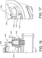
- FIG. 16 shows an electronic printed circuit board (PCB) 1600 that has been place on, and attached to, the electronic casing or meter enclosure 1400.
- PCB printed circuit board
- FIG. 17 shows two surfaces 1700, 1702 of the wiring guide or plug 1202.
- an automated tool is used to push the upper surface 1700 to the level of the lower surface 1702. This pushes a first or upper portion of the plug to side with respect to a second or lower portion of the plug. While the first portion moves, the wires of the wiring guide do not move, and then become exposed. Accordingly, the movement of the upper surface 1700 lowers the wire guides 1304, 1306, which exposes the wires passing through them (as seen in FIG. 18 ). The exposed wires are then in position to be soldered to the printed circuit board.
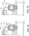
- FIG. 18 shows an exposed wire 1308 (and wire 1310, hidden in the view), which was exposed as the wire guide 1304 (and wire guide 1306, hidden in the view) of the wiring guide or plug 1202 moved downwardly, as the wire guide as the surface 1700 was pushed to the level of the surface 1702. Accordingly, the wires 1308 (shown, and wire 1310 directly behind wire 1308) are at a level slightly higher than the PCB 1600.
- FIG. 19 shows the wire 1308 extending from the wire guide 1304 of the plug 1202. An automated tool (not shown) has pushed the wire 1308 into contact with the PCB. Thus, the wires 1308, 1310 extend just over the top of the PCB 1600, which locates it appropriately to be soldered to the PCB.
- FIGS. 20A and 20B show a first example of a two-part plug or wiring guide 1202.
- a first portion 1300 of the plug includes two wire guides 1304, 1306 and a second portion 1302 attaches to an enclosure 1204 of a transducer assembly 1200 (both seen in FIG. 12 ).
- the first portion 1300 is in an extended position, which covers and protects the wires of the transducer unit.
- An upper surface 1702 and a lower surface 1704 are at different elevations. When in the upper position (as seen in FIG. 17 ) the upper surface 1702 may be pushed down to the level of, and flush with, the lower surface 1702 (as seen in FIG. 18 ).
- FIG. 20B shows that part of the upper portion 1300 has been pushed down into the lower portion 1302.
- the wires are not visible in this view for clarity, but are seen in FIGS. 18 and 19 .
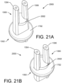
- FIGS. 21A and 21B show a second example of a two-part plug or wiring guide 2000.
- the second example differs from the example of FIG. 20 in that a stop 2002 affirmatively stops motion of the first portion 1300 relative to the second portion 1302.
- a first portion 1300 of the plug includes two wire guides 1304, 1306 and a second portion 1302 attaches to an enclosure 1204 of a transducer assembly 1200 (both seen in FIG. 12 ).
- the first portion 1300 is in an extended position, which covers and protects the wires of the transducer unit.
- the stop 2002 and a lower surface 1704 are at different elevations.
- FIG. 21B shows that part of the upper portion 1300 has been pushed down into the lower portion 1302.
- the wires are not visible in this view for clarity, but are seen in FIGS. 18 and 19 .
- FIGS. 22A-E show example wiring guides (i.e., plugs insertable into an enclosure of a transducer assembly).
- the wiring guide may include two portions that slide with respect to each other, and which are connected to an enclosure of a transducer assembly.
- movement of one portion of the wiring guide results in breakage of a frangible portion of one or both portions of the wiring guide.
- a first surface 1700 of a first portion of the wiring guide is depressed to the level of a second surface 1702 of a second portion of the wiring guide.
- an automated tool pushes on surface 1700, thereby breaking the thin plastic area 2100.
- the thin plastic area 2100 may be a frangible or breakable seal or perforation.
- the surface 1700 and the wire guides are lowered, until the surface 1700 is flush with surface 1702.
- the lowering of the wire guides breaks the seal or perforation 2100.
- wire in the channels defined by each wire guide is exposed. Accordingly, the wire is covered during storage and transport, but is exposed after movement of the surface 1700 to the level of surface 1702.
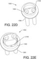
- FIGS. 22D and E shows the first and second portions of a wiring guide 1202 in an opposite orientation to that seen in FIG. 22A .
- a first portion 1300 and a second portion 1302 are friction-fit, so allow the first portion 1300 to slide with respect to the second portion 1302 between first and second positions.
- the first portion 1302 is in a first position which protects and encloses wiring of the transducer device.
- the first portion has slid into a second position, which would reveal the wiring (shown in the views of FIG. 18 and 19 ).
- ribs 2102 may be defined in the plug, to guide and retain a connection between upper and lower parts of the plug or wiring guide.
- the wiring guide e.g., plug 1202 of FIG. 13 and plug 2000 of FIG. 21
- the wiring guide may have an upper portion including the surface 1700 (seen in FIG. 21 ) and the two wire guides 1304, 1306 (seen in FIG. 13 ). Additionally, the wiring guide has a lower portion including the surface 1702 (seen in FIG. 21 ) and the connecting portion for attachment to the enclosure of the transducer.
- FIGS. 12 through 22 show examples of a transducer enclosure to protect and position transducer wiring, such as in an automated manufacturing environment.
- a transducer in a first example of a transducer assembly, includes a first wire and a second wire.
- a housing may at least partially enclose the transducer.
- a plug may be disposed in an opening of the housing.
- An example plug may include a first portion coupled to the opening of the housing and a second portion encircling the first wire and the second wire.
- the second portion of the plug is movably coupled to the first portion of the plug, such that the second portion is movable from a first position in which the first wire and the second wire are recessed in the second portion, to a second position in which the first wire and the second wire protrude from the second portion.
- the second portion may include a first wire guide and a second wire guide.
- the first wire guide and the second wire guide may define a first channel and a second channel, respectively.
- the first wire and the second wire may be located at least in part within the first channel and the second channel, respectively.
- the first portion may include a first frictional surface and the second portion may include a second frictional surface.
- contact between the first frictional surface and second frictional surface resists movement of the second portion with respect to the first portion.
- the first portion may include a first frictional surface and the second portion may include a second frictional surface in contact with the first frictional surface.
- movement overcoming friction between the first frictional surface and second frictional surface exposes portions of the first wire and portions of the second wire.
- a first channel and a second channel are defined within the second portion.
- an end of the first wire and an end of the second wire are enclosed within the first channel and the second channel, respectively.
- a first channel and a second channel are defined within the second portion.
- an end of the first wire and an end of the second wire extend out of the first channel and the second channel, respectively.
- the transducer assembly may additionally include a circuit board.
- the transducer assembly when the second portion is in the second position, an end of the first wire and an end of the second wire extend out of a first channel defined in the second portion and a second channel defined in the second channel, respectively.
- the wires may extend by a distance sufficient for the first wire and the second wire to contact the circuit board.
- the transducer assembly may additionally include a stop disposed on the second portion to limit relative movement of the second portion with respect to the first portion.
- a transducer assembly may include a transducer having a first wire and a second wire.
- a housing may at least partially enclose the transducer.
- a plug may be disposed in an opening of the housing.
- the plug may include a first portion coupled to the opening of the housing and a second portion.
- the second portion may include a first wire guide and a second wire guide.
- the first wire guide and the second wire guide may define a first channel and a second channel, respectively.
- portions of the first wire and portions of the second wire may be located at least in part within the first channel and the second channel, respectively.
- the second portion of the plug may be movably coupled to the first portion of the plug between a first position and a second position.
- an end of the first wire and an end of the second wire are encased in the first position and exposed when the second position.
- the first portion may include a first frictional surface and the second portion may include a second frictional surface in contact with the first frictional surface.
- the transducer assembly may additionally include a circuit board.
- the second portion of the plug may be movably coupled to the first portion of the plug, such as to allow movement between a first position and a second position. In the example, when the second portion is in the second position, an end of the first wire and an end of the second wire extend out of the first channel and the second channel, respectively, by a distance sufficient for the first wire and the second wire to contact the circuit board.
- the transducer assembly may additionally include a stop disposed on the second portion to limit relative movement of the second portion with respect to the first portion.
- the first portion may additionally include a first frictional surface and the second portion may additionally include a second frictional surface.
- the first frictional surface and second frictional surface are in contact.
- a metering device may be manufactured according to one or more actions and/or techniques.
- a housing of a transducer may be attached to a pipe.
- a printed circuit board (PCB) may be attached to an assembly adjacent to the housing.
- a force may be applied to move a first portion of the housing to expose wires of the metering device. The exposed wires bending the wiring to contact the PCB; and electrically connecting the wiring to the PCB.
- the force applied to move the first portion may include applying force to the first portion until a stop contacts a second portion of the housing.
- the force applied to move the first portion may include applying force to the first portion until a surface of the first portion is substantially planar with a surface of a second portion of the housing.
- the force applied to move the first portion may include applying force to break a seal of the housing.
- the force applied to move the first portion may include sliding the first portion against a second portion of the housing.
- the force applied to move the first portion may include sliding wire guides against wires of the metering device to thereby expose the wires.
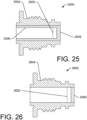
- FIGS. 23 through 26 show example designs of transducer assemblies.
- the designs are made of plastic that includes reinforcing material (e.g., glass fiber) and/or plastic that does not include reinforcing material or includes less reinforcing material.
- a bi-material enclosure is configured for use in an acoustic sensor assembly, such as for use in a water or gas metering applications.
- a plastic housing with mechanical reinforcements e.g., 40% glass fiber
- Use of a plastic sleeve without fiber reinforcements may result in transducer assemblies with more consistent signal transmission characteristics.
- a less-reinforced plastic sleeve may result in more homogeneous and/or consistent data from different transducer assemblies under the same or similar conditions.
- acoustic signal loss or attenuation may be reduced if a material of the less-reinforced sleeve (e.g., sleeve 2506 and endcap 2508 of FIG. 25 ) is selected to have an impedance of a piezo device and/or water. Additionally or alternatively, the thickness of the sleeve and/or endcap may be selected to be an odd multiple of a quarter wavelength of an acoustic signal to be measured by a piezo and/or transducer device.
- a material of the less-reinforced sleeve e.g., sleeve 2506 and endcap 2508 of FIG. 25
- the thickness of the sleeve and/or endcap may be selected to be an odd multiple of a quarter wavelength of an acoustic signal to be measured by a piezo and/or transducer device.
- reinforced material as a sleeve, endcap, and/or other conduit of an acoustic signal may attenuate the acoustic signal because of diffraction, deflection, diffusion, dispersion, etc.
- the use of reinforcing fibers as the signal conduit may result in variations of fiber content, variations in fiber alignment, and/or failure of a fiber coating to cohesively contain the fibers and/or to provide an entry path for gas, water or other fluid along the fibers. Such entry points may be exposed by, and/or result from, wear during use.
- the bi-material transducer enclosure provides a high resistance to pressure, less acoustic signal attenuation, and/or high reproducibility of signal-transmission characteristics between transducer assemblies operating under similar conditions.
- FIG. 23 shows an example sensor unit or transducer assembly 2300 including a transducer device 2302.
- a piezo device 2302 is shown within the housing 2304.
- the housing 2304 of the transducer is made of a plastic that is zero percent (or alternatively, 0% to 15%) glass fiber (GF) or other reinforcing material.
- GF glass fiber
- the housing or enclosure 2304 is consistent with a high signal level by the piezo device and/or high signal transmissivity through the housing 2304.
- FIG. 24 shows an example sensor unit or transducer assembly 2400 including a transducer 2402.
- a piezo device 2402 is shown within the housing 2404.
- the housing 2400 of the transducer is made of a plastic that is approximately 40% percent glass fiber (e.g., 15% to 65% glass fiber).
- a plastic enclosure made with glass fiber provides high strength characteristics and high resistance to pressure.
- FIG. 25 shows an example sensor unit or transducer assembly 2500 including a transducer device 2502 (e.g., ultrasonic sensor such as a piezo device).
- a piezo device 2502 is shown within the housing.
- the housing has a bi-material design, including portions that are made of plastic with reinforcing material (e.g., glass fiber) and portions that are made of plastic without reinforcing material.
- an outer tube 2504 is made of plastic with fiber and forms a high-strength shell of the sensor unit 2500.
- An inner tube 2506 of the sensor unit 2500 made of plastic without fiber.
- the inner tube 2506 also forms, and/or is connected to, an end-portion or cap 2508, which is also made of plastic without fiber.
- the sensor unit 2500 provides strength and excellent ultrasonic signal transmission characteristics.
- the outer tube 2504 has is stronger than the inner tube 2506, and results in a sensor unit 2500 having strength and resistance to pressure.
- the inner tube 2506 has better ultrasonic signal conduction than the outer tube 2504, and the fiber-free construction results in a higher signal level from an ultrasonic sensor or piezo device. Additionally, without variability in fiber content and distribution, the use of inner tubes made with non-fiber plastic results in high signal reproducibility and consistency. That is, the use of fiber-free inner sleeves 2506 and end-portions 2508 results in production of sensor units that are more similar or homogenous in signal detection and ultrasonic transducer response, due at least in part to their fiber-free construction.
- the bi-material ultrasonic sensor unit 2500 results in production of transducer assemblies that provide excellent and consistent signal transmission from a pipe to a piezo device, high strength and water pressure resistance, and excellent protection against water contamination.
- FIG. 26 shows an example sensor unit or transducer assembly 2600 including a transducer device 2602 (e.g., ultrasonic sensor such as a piezo device).
- a piezo device 2602 is shown within the housing.
- the housing has a bi-material design, including portions that are made of plastic with fiber and portions that are made of plastic without fiber.
- a tube 2604 is made of plastic with fiber, and forms a high-strength shell of the sensor unit 2600.
- An end-portion or end cap 2606 of the sensor unit 2600 made of plastic without fiber and provides excellent ultrasonic signal transmission from a pipe to an ultrasonic sensor device (e.g., a piezo device).
- the transducer assembly 2600 includes both strength and good ultrasonic signal transmission.
- the tube 2604 has strength derived in part from a reinforced plastic, e.g., glass fiber design, and results in a sensor unit 2600 having considerable strength and resistance to pressure.
- the end-portion or end cap 2606 has better ultrasonic signal conduction than the tube 2604, and the fiber-free construction results better ultrasonic signal transfer from a pipe to an ultrasonic transducer device. Additionally, the transducer device will produce a more accurate and/or a higher signal level. Without variability in fiber content and distribution, the end-portion 2606 made of non-fiber plastic results in high signal reproducibility and consistency. Accordingly, the bi-material ultrasonic sensor unit 2600 results in production of transducer assemblies that provide excellent and consistent signal transmission from a pipe to a piezo device, and high strength and water pressure resistance and protection.
- FIGS. 23 through 26 show examples of an enclosure for a transducer made of multiple materials, to provide strength and ultrasonic signal conduction.
- a transducer assembly in a first example, includes a first tube, a second tube and an end-portion.
- the first tube may be made of a mechanically reinforced plastic material.
- the second tube may be made of a first unreinforced plastic material and may be disposed within the first tube.
- the end-portion may be made of a second unreinforced plastic material and may be connected to the second tube.
- the mechanically reinforced plastic material comprises plastic with glass fiber.
- the first unreinforced plastic material and the second unreinforced plastic material may include plastic free of glass fiber.
- the first unreinforced plastic material and the second unreinforced plastic material may be the same material.
- the first tube may be made of approximately 40% glass fiber by weight.
- the second unreinforced plastic material of the end-portion attenuates an ultrasonic signal less than the mechanically reinforced plastic material of the first tube.
- the transducer assembly may additionally include an ultrasonic transducer in contact with the end-portion.
- the transducer assembly may additionally include a piezo electric transducer in contact with the end-portion.
- the transducer assembly may additionally include an ultrasonic transducer.
- an outside diameter of the ultrasonic transducer is less than an inside diameter of the second tube and the ultrasonic transducer is coupled to the end-portion.
- the first tube has greater mechanical resistance than the second tube and the second unreinforced plastic material of the end-portion attenuates an ultrasonic signal less than the mechanically reinforced plastic material of the first tube.
- a sensor unit for a meter may include a tube, a tube-end, and an ultrasonic transducer.
- the tube may be made of a mechanically reinforced plastic material.
- the tube-end may be made of an unreinforced plastic material.
- the ultrasonic transducer may be attached to the tube-end.
- the tube is a first tube
- the sensor unit may additionally include a second tube.
- the second tube may be disposed within the first tube and may be made of the same material as the tube-end.
- the mechanically reinforced plastic material may be made of plastic with glass fiber and the second tube and tube-end may be made of unreinforced plastic material.
- the first tube has better mechanical resistance than the second tube and a material of the second tube and the tube-end attenuates a signal from a pipe less than a material of the first tube.
- the mechanically reinforced plastic material and the unreinforced plastic material are made of a same resin type, but have differing levels of glass fiber and/or other mechanical reinforcement material.
- the ultrasonic transducer is a piezoelectric transducer in contact with the tube-end.
- the mechanically reinforced plastic material and the unreinforced plastic material are made of a same resin type and the mechanically reinforced plastic material comprises glass fiber.
- a transducer assembly may include a first tube, a second tube, and an end-portion.
- the first tube may be made of plastic with a reinforcing material and the second tube may be made of plastic, having less reinforcing material (e.g., glass fiber) than the plastic of the first tube or no reinforcing material (e.g., no glass fiber).
- the end-portion may be made of plastic without reinforcing material and may be connected to the second tube.
- the transducer assembly may additionally include an ultrasonic transducer in contact with the end-portion.
- the plastic of the second tube and plastic of the end-portion may be made of plastic without glass fiber.
- the plastic of the second tube has no glass fiber.
Landscapes
- Physics & Mathematics (AREA)
- General Physics & Mathematics (AREA)
- Biochemistry (AREA)
- Life Sciences & Earth Sciences (AREA)
- Chemical & Material Sciences (AREA)
- Analytical Chemistry (AREA)
- Health & Medical Sciences (AREA)
- General Health & Medical Sciences (AREA)
- Immunology (AREA)
- Pathology (AREA)
- Fluid Mechanics (AREA)
- Acoustics & Sound (AREA)
- Electromagnetism (AREA)
- Transducers For Ultrasonic Waves (AREA)
- Casings For Electric Apparatus (AREA)
Claims (10)
- Wandleranordnung (200), umfassend:ein erstes Rohr (300), das ein mechanisch verstärktes Kunststoffmaterial umfasst;ein zweites Rohr (2506), das ein erstes unverstärktes Kunststoffmaterial umfasst, wobei das zweite Rohr innerhalb des ersten Rohrs angeordnet ist;einen Endabschnitt (2508), der ein zweites unverstärktes Kunststoffmaterial umfasst, wobei der Endabschnitt mit dem zweiten Rohr verbunden ist; undeinen Wandler, wobei der Wandler in Kontakt mit dem Endabschnitt ist, der das zweite unverstärkte Kunststoffmaterial umfasst, und ein Ultraschallwandler ist,wobei das erste unverstärkte Kunststoffmaterial und das zweite unverstärkte Kunststoffmaterial glasfaserfreien Kunststoff umfassen.
- Wandleranordnung nach Anspruch 1, wobei:
das mechanisch verstärkte Kunststoffmaterial Kunststoff mit Glasfaser umfasst. - Wandleranordnung nach Anspruch 1 oder Anspruch 2, wobei:
das erste unverstärkte Kunststoffmaterial und das zweite unverstärkte Kunststoffmaterial ein gleiches Material sind. - Wandleranordnung nach einem der vorhergehenden Ansprüche, wobei:
das erste Rohr zu etwa 40 Gew.-% Glasfaser umfasst. - Wandleranordnung nach einem der vorhergehenden Ansprüche, wobei:
das zweite unverstärkte Kunststoffmaterial des Endabschnitts dazu eingerichtet ist, ein Ultraschallsignal zu dämpfen, das geringer als das mechanisch verstärkte Kunststoffmaterial des ersten Rohrs ist. - Wandleranordnung nach einem der vorhergehenden Ansprüche, wobei:ein Außendurchmesser des Ultraschallwandlers kleiner als ein Innendurchmesser des zweiten Rohrs ist; undder Ultraschallwandler mit dem Endabschnitt gekoppelt ist.
- Wandleranordnung nach einem der vorhergehenden Ansprüche, wobei:das erste Rohr einen größeren mechanischen Widerstand als das zweite Rohr aufweist; unddas zweite unverstärkte Kunststoffmaterial des Endabschnitts dazu eingerichtet ist, ein Ultraschallsignal zu dämpfen, das geringer als das mechanisch verstärkte Kunststoffmaterial des ersten Rohrs ist.
- Wandleranordnung nach einem der vorhergehenden Ansprüche, wobei:der Ultraschallwandler ein piezoelektrischer Wandler ist; undeine Dicke des Endabschnitts so ausgelegt ist, dass sie ein ungerades Vielfaches einer Viertelwellenlänge eines akustischen Signals ist, das durch den piezoelektrischen Wandler zu messen ist.
- Sensoreinheit (2500) für ein Messgerät, die die Wandleranordnung nach einem der vorhergehenden Ansprüche umfasst, wobei:der Endabschnitt ein Rohrende ist;der Ultraschallwandler am Rohrende angebracht ist; unddas zweite Rohr das gleiche Material wie das Rohrende umfasst.
- Sensoreinheit nach Anspruch 9, wobei:
das mechanisch verstärkte Kunststoffmaterial und der unverstärkte Kunststoff aus einer gleichen Harzart hergestellt sind.
Priority Applications (1)
| Application Number | Priority Date | Filing Date | Title |
|---|---|---|---|
| EP25163504.1A EP4585918A3 (de) | 2019-07-02 | 2020-07-02 | Wandlergehäuse aus mehreren materialien |
Applications Claiming Priority (4)
| Application Number | Priority Date | Filing Date | Title |
|---|---|---|---|
| US201962869988P | 2019-07-02 | 2019-07-02 | |
| US16/588,817 US11359948B2 (en) | 2019-07-02 | 2019-09-30 | Transducer enclosure to protect and position transducer wiring |
| US16/588,844 US11215488B2 (en) | 2019-07-02 | 2019-09-30 | Transducer enclosure with variable moisture proofing |
| US16/588,858 US11287299B2 (en) | 2019-07-02 | 2019-09-30 | Multi-material transducer enclosure |
Related Child Applications (2)
| Application Number | Title | Priority Date | Filing Date |
|---|---|---|---|
| EP25163504.1A Division EP4585918A3 (de) | 2019-07-02 | 2020-07-02 | Wandlergehäuse aus mehreren materialien |
| EP25163504.1A Division-Into EP4585918A3 (de) | 2019-07-02 | 2020-07-02 | Wandlergehäuse aus mehreren materialien |
Publications (2)
| Publication Number | Publication Date |
|---|---|
| EP3760321A1 EP3760321A1 (de) | 2021-01-06 |
| EP3760321B1 true EP3760321B1 (de) | 2025-04-16 |
Family
ID=71465122
Family Applications (2)
| Application Number | Title | Priority Date | Filing Date |
|---|---|---|---|
| EP20183819.0A Active EP3760982B1 (de) | 2019-07-02 | 2020-07-02 | Wasserzähler umfassend ein wandlergehäuse mit variabler feuchtigkeitsabdichtung |
| EP20183829.9A Active EP3760321B1 (de) | 2019-07-02 | 2020-07-02 | Multimaterialwandlergehäuse |
Family Applications Before (1)
| Application Number | Title | Priority Date | Filing Date |
|---|---|---|---|
| EP20183819.0A Active EP3760982B1 (de) | 2019-07-02 | 2020-07-02 | Wasserzähler umfassend ein wandlergehäuse mit variabler feuchtigkeitsabdichtung |
Country Status (1)
| Country | Link |
|---|---|
| EP (2) | EP3760982B1 (de) |
Families Citing this family (2)
| Publication number | Priority date | Publication date | Assignee | Title |
|---|---|---|---|---|
| US11287299B2 (en) * | 2019-07-02 | 2022-03-29 | Itron Global Sarl | Multi-material transducer enclosure |
| CN115877188B (zh) * | 2023-03-04 | 2023-05-26 | 大禹节水(天津)有限公司 | 一种超声波水表电路检测装置 |
Citations (1)
| Publication number | Priority date | Publication date | Assignee | Title |
|---|---|---|---|---|
| US20080276724A1 (en) * | 2007-05-10 | 2008-11-13 | Daniel Measurement And Control, Inc. | Systems and methods of a transducer having a plastic matching layer |
Family Cites Families (6)
| Publication number | Priority date | Publication date | Assignee | Title |
|---|---|---|---|---|
| US7217314B2 (en) * | 2005-01-10 | 2007-05-15 | Gore Enterprise Holdings, Inc. | Venting system for minimizing condensation in a lighting assembly |
| EP2083251A1 (de) * | 2007-12-13 | 2009-07-29 | Kamstrup A/S | Verbrauchsmesser mit mindestens zwei Gehäuseteilen |
| JP5086814B2 (ja) * | 2008-01-07 | 2012-11-28 | 株式会社キーエンス | 流量計 |
| US10517666B2 (en) * | 2013-10-25 | 2019-12-31 | Ablative Solutions, Inc. | Apparatus for effective ablation and nerve sensing associated with denervation |
| JP5634636B1 (ja) * | 2014-06-24 | 2014-12-03 | 東京計装株式会社 | 超音波流量計 |
| EP3308145B1 (de) * | 2015-06-12 | 2022-04-20 | LacriSciences, LLC | Verfahren zum nachweis von chemischen und biologischen mitteln durch oberflächen-plasmon-resonanz |
-
2020
- 2020-07-02 EP EP20183819.0A patent/EP3760982B1/de active Active
- 2020-07-02 EP EP20183829.9A patent/EP3760321B1/de active Active
Patent Citations (1)
| Publication number | Priority date | Publication date | Assignee | Title |
|---|---|---|---|---|
| US20080276724A1 (en) * | 2007-05-10 | 2008-11-13 | Daniel Measurement And Control, Inc. | Systems and methods of a transducer having a plastic matching layer |
Also Published As
| Publication number | Publication date |
|---|---|
| EP3760982B1 (de) | 2023-04-19 |
| EP3760982A1 (de) | 2021-01-06 |
| EP3760321A1 (de) | 2021-01-06 |
Similar Documents
| Publication | Publication Date | Title |
|---|---|---|
| US11555722B2 (en) | Transducer enclosure with variable moisture proofing | |
| EP3760321B1 (de) | Multimaterialwandlergehäuse | |
| DK2513610T3 (en) | ULTRASONIC FLOW METER HOUSE MADE BY A MONOLITIC POLYMER STRUCTURE | |
| US8869639B2 (en) | Mounting element for installing sensors without play | |
| CN102859335A (zh) | 具有锁定机构的超声波耗量测量仪 | |
| US20120132008A1 (en) | Fiber optic load measurement device | |
| US9377335B2 (en) | Flow rate sensor probe having contactless force trasnmitting structure | |
| US20150209828A1 (en) | Ultrasonic transducer, and method for producing an ultrasonic transducer | |
| CN112292586A (zh) | 超声波传感器装置 | |
| CN107144929A (zh) | 一种无螺钉密封光缆接头盒 | |
| KR20100113815A (ko) | 파이프라인 모니터링 시스템 | |
| JP2006047154A (ja) | 光ファイバ温度センサ及びその製造方法 | |
| CN118310672B (zh) | 一种连续渗压传感器及其工作方法 | |
| CN109405903B (zh) | 用于流量计的具有拉出装置的声探头 | |
| US20040190590A1 (en) | Apparatus for determining the temperature of a flowing medium in conduit and method for producing the apparatus | |
| EP3382351B1 (de) | Ultraschalldurchflussmesser | |
| CN109405902B (zh) | 一种安装在流量计的量管中的声探头 | |
| CN105570457B (zh) | 用于管道传感器的盖体 | |
| RU2608635C2 (ru) | Оптический преобразователь с интегрированным проходником | |
| CN109405904B (zh) | 用于流量计的具有加强板的声探头 | |
| GB2409289A (en) | Feedthrough optical waveguide strain relief | |
| CN201247107Y (zh) | 磁性热电偶 | |
| CN105387896A (zh) | 电子式水表 | |
| KR950003846A (ko) | 광도파로모듈 | |
| JPH10239182A (ja) | 光ファイバ物理量センサ |
Legal Events
| Date | Code | Title | Description |
|---|---|---|---|
| PUAI | Public reference made under article 153(3) epc to a published international application that has entered the european phase |
Free format text: ORIGINAL CODE: 0009012 |
|
| STAA | Information on the status of an ep patent application or granted ep patent |
Free format text: STATUS: THE APPLICATION HAS BEEN PUBLISHED |
|
| AK | Designated contracting states |
Kind code of ref document: A1 Designated state(s): AL AT BE BG CH CY CZ DE DK EE ES FI FR GB GR HR HU IE IS IT LI LT LU LV MC MK MT NL NO PL PT RO RS SE SI SK SM TR |
|
| AX | Request for extension of the european patent |
Extension state: BA ME |
|
| STAA | Information on the status of an ep patent application or granted ep patent |
Free format text: STATUS: REQUEST FOR EXAMINATION WAS MADE |
|
| 17P | Request for examination filed |
Effective date: 20210706 |
|
| RBV | Designated contracting states (corrected) |
Designated state(s): AL AT BE BG CH CY CZ DE DK EE ES FI FR GB GR HR HU IE IS IT LI LT LU LV MC MK MT NL NO PL PT RO RS SE SI SK SM TR |
|
| STAA | Information on the status of an ep patent application or granted ep patent |
Free format text: STATUS: EXAMINATION IS IN PROGRESS |
|
| 17Q | First examination report despatched |
Effective date: 20221026 |
|
| P01 | Opt-out of the competence of the unified patent court (upc) registered |
Effective date: 20230519 |
|
| GRAP | Despatch of communication of intention to grant a patent |
Free format text: ORIGINAL CODE: EPIDOSNIGR1 |
|
| STAA | Information on the status of an ep patent application or granted ep patent |
Free format text: STATUS: GRANT OF PATENT IS INTENDED |
|
| INTG | Intention to grant announced |
Effective date: 20241112 |
|
| GRAS | Grant fee paid |
Free format text: ORIGINAL CODE: EPIDOSNIGR3 |
|
| GRAA | (expected) grant |
Free format text: ORIGINAL CODE: 0009210 |
|
| STAA | Information on the status of an ep patent application or granted ep patent |
Free format text: STATUS: THE PATENT HAS BEEN GRANTED |
|
| AK | Designated contracting states |
Kind code of ref document: B1 Designated state(s): AL AT BE BG CH CY CZ DE DK EE ES FI FR GB GR HR HU IE IS IT LI LT LU LV MC MK MT NL NO PL PT RO RS SE SI SK SM TR |
|
| REG | Reference to a national code |
Ref country code: GB Ref legal event code: FG4D |
|
| REG | Reference to a national code |
Ref country code: CH Ref legal event code: EP Ref country code: DE Ref legal event code: R096 Ref document number: 602020049438 Country of ref document: DE |
|
| REG | Reference to a national code |
Ref country code: IE Ref legal event code: FG4D |
|
| REG | Reference to a national code |
Ref country code: ES Ref legal event code: FG2A Ref document number: 3031582 Country of ref document: ES Kind code of ref document: T3 Effective date: 20250709 |
|
| PGFP | Annual fee paid to national office [announced via postgrant information from national office to epo] |
Ref country code: GB Payment date: 20250508 Year of fee payment: 6 |
|
| PGFP | Annual fee paid to national office [announced via postgrant information from national office to epo] |
Ref country code: FR Payment date: 20250508 Year of fee payment: 6 |
|
| REG | Reference to a national code |
Ref country code: NL Ref legal event code: MP Effective date: 20250416 |
|
| PG25 | Lapsed in a contracting state [announced via postgrant information from national office to epo] |
Ref country code: NL Free format text: LAPSE BECAUSE OF FAILURE TO SUBMIT A TRANSLATION OF THE DESCRIPTION OR TO PAY THE FEE WITHIN THE PRESCRIBED TIME-LIMIT Effective date: 20250416 |
|
| REG | Reference to a national code |
Ref country code: AT Ref legal event code: MK05 Ref document number: 1785237 Country of ref document: AT Kind code of ref document: T Effective date: 20250416 |
|
| PG25 | Lapsed in a contracting state [announced via postgrant information from national office to epo] |
Ref country code: PT Free format text: LAPSE BECAUSE OF FAILURE TO SUBMIT A TRANSLATION OF THE DESCRIPTION OR TO PAY THE FEE WITHIN THE PRESCRIBED TIME-LIMIT Effective date: 20250818 Ref country code: FI Free format text: LAPSE BECAUSE OF FAILURE TO SUBMIT A TRANSLATION OF THE DESCRIPTION OR TO PAY THE FEE WITHIN THE PRESCRIBED TIME-LIMIT Effective date: 20250416 |
|
| PGFP | Annual fee paid to national office [announced via postgrant information from national office to epo] |
Ref country code: ES Payment date: 20250806 Year of fee payment: 6 |
|
| PGFP | Annual fee paid to national office [announced via postgrant information from national office to epo] |
Ref country code: DE Payment date: 20250507 Year of fee payment: 6 |
|
| REG | Reference to a national code |
Ref country code: LT Ref legal event code: MG9D |
|
| PG25 | Lapsed in a contracting state [announced via postgrant information from national office to epo] |
Ref country code: GR Free format text: LAPSE BECAUSE OF FAILURE TO SUBMIT A TRANSLATION OF THE DESCRIPTION OR TO PAY THE FEE WITHIN THE PRESCRIBED TIME-LIMIT Effective date: 20250717 Ref country code: NO Free format text: LAPSE BECAUSE OF FAILURE TO SUBMIT A TRANSLATION OF THE DESCRIPTION OR TO PAY THE FEE WITHIN THE PRESCRIBED TIME-LIMIT Effective date: 20250716 |
|
| PG25 | Lapsed in a contracting state [announced via postgrant information from national office to epo] |
Ref country code: PL Free format text: LAPSE BECAUSE OF FAILURE TO SUBMIT A TRANSLATION OF THE DESCRIPTION OR TO PAY THE FEE WITHIN THE PRESCRIBED TIME-LIMIT Effective date: 20250416 |
|
| PGFP | Annual fee paid to national office [announced via postgrant information from national office to epo] |
Ref country code: IT Payment date: 20250710 Year of fee payment: 6 |
|
| PG25 | Lapsed in a contracting state [announced via postgrant information from national office to epo] |
Ref country code: BG Free format text: LAPSE BECAUSE OF FAILURE TO SUBMIT A TRANSLATION OF THE DESCRIPTION OR TO PAY THE FEE WITHIN THE PRESCRIBED TIME-LIMIT Effective date: 20250416 |
|
| PG25 | Lapsed in a contracting state [announced via postgrant information from national office to epo] |
Ref country code: HR Free format text: LAPSE BECAUSE OF FAILURE TO SUBMIT A TRANSLATION OF THE DESCRIPTION OR TO PAY THE FEE WITHIN THE PRESCRIBED TIME-LIMIT Effective date: 20250416 |
|
| PG25 | Lapsed in a contracting state [announced via postgrant information from national office to epo] |
Ref country code: AT Free format text: LAPSE BECAUSE OF FAILURE TO SUBMIT A TRANSLATION OF THE DESCRIPTION OR TO PAY THE FEE WITHIN THE PRESCRIBED TIME-LIMIT Effective date: 20250416 |
|
| PG25 | Lapsed in a contracting state [announced via postgrant information from national office to epo] |
Ref country code: RS Free format text: LAPSE BECAUSE OF FAILURE TO SUBMIT A TRANSLATION OF THE DESCRIPTION OR TO PAY THE FEE WITHIN THE PRESCRIBED TIME-LIMIT Effective date: 20250716 |
|
| PG25 | Lapsed in a contracting state [announced via postgrant information from national office to epo] |
Ref country code: IS Free format text: LAPSE BECAUSE OF FAILURE TO SUBMIT A TRANSLATION OF THE DESCRIPTION OR TO PAY THE FEE WITHIN THE PRESCRIBED TIME-LIMIT Effective date: 20250816 |
|
| PG25 | Lapsed in a contracting state [announced via postgrant information from national office to epo] |
Ref country code: LV Free format text: LAPSE BECAUSE OF FAILURE TO SUBMIT A TRANSLATION OF THE DESCRIPTION OR TO PAY THE FEE WITHIN THE PRESCRIBED TIME-LIMIT Effective date: 20250416 |
|
| PG25 | Lapsed in a contracting state [announced via postgrant information from national office to epo] |
Ref country code: SM Free format text: LAPSE BECAUSE OF FAILURE TO SUBMIT A TRANSLATION OF THE DESCRIPTION OR TO PAY THE FEE WITHIN THE PRESCRIBED TIME-LIMIT Effective date: 20250416 Ref country code: DK Free format text: LAPSE BECAUSE OF FAILURE TO SUBMIT A TRANSLATION OF THE DESCRIPTION OR TO PAY THE FEE WITHIN THE PRESCRIBED TIME-LIMIT Effective date: 20250416 |
|
| REG | Reference to a national code |
Ref country code: DE Ref legal event code: R097 Ref document number: 602020049438 Country of ref document: DE |
|
| PG25 | Lapsed in a contracting state [announced via postgrant information from national office to epo] |
Ref country code: CZ Free format text: LAPSE BECAUSE OF FAILURE TO SUBMIT A TRANSLATION OF THE DESCRIPTION OR TO PAY THE FEE WITHIN THE PRESCRIBED TIME-LIMIT Effective date: 20250416 |
|
| PG25 | Lapsed in a contracting state [announced via postgrant information from national office to epo] |
Ref country code: EE Free format text: LAPSE BECAUSE OF FAILURE TO SUBMIT A TRANSLATION OF THE DESCRIPTION OR TO PAY THE FEE WITHIN THE PRESCRIBED TIME-LIMIT Effective date: 20250416 |
|
| PG25 | Lapsed in a contracting state [announced via postgrant information from national office to epo] |
Ref country code: RO Free format text: LAPSE BECAUSE OF FAILURE TO SUBMIT A TRANSLATION OF THE DESCRIPTION OR TO PAY THE FEE WITHIN THE PRESCRIBED TIME-LIMIT Effective date: 20250416 Ref country code: SK Free format text: LAPSE BECAUSE OF FAILURE TO SUBMIT A TRANSLATION OF THE DESCRIPTION OR TO PAY THE FEE WITHIN THE PRESCRIBED TIME-LIMIT Effective date: 20250416 |
|
| PLBE | No opposition filed within time limit |
Free format text: ORIGINAL CODE: 0009261 |
|
| STAA | Information on the status of an ep patent application or granted ep patent |
Free format text: STATUS: NO OPPOSITION FILED WITHIN TIME LIMIT |
|
| REG | Reference to a national code |
Ref country code: CH Ref legal event code: H13 Free format text: ST27 STATUS EVENT CODE: U-0-0-H10-H13 (AS PROVIDED BY THE NATIONAL OFFICE) Effective date: 20260224 |
|
| REG | Reference to a national code |
Ref country code: CH Ref legal event code: L10 Free format text: ST27 STATUS EVENT CODE: U-0-0-L10-L00 (AS PROVIDED BY THE NATIONAL OFFICE) Effective date: 20260225 |
|
| PG25 | Lapsed in a contracting state [announced via postgrant information from national office to epo] |
Ref country code: LU Free format text: LAPSE BECAUSE OF NON-PAYMENT OF DUE FEES Effective date: 20250702 |
|
| 26N | No opposition filed |
Effective date: 20260119 |
|
| REG | Reference to a national code |
Ref country code: BE Ref legal event code: MM Effective date: 20250731 |
|
| PG25 | Lapsed in a contracting state [announced via postgrant information from national office to epo] |
Ref country code: BE Free format text: LAPSE BECAUSE OF NON-PAYMENT OF DUE FEES Effective date: 20250731 |
|
| PG25 | Lapsed in a contracting state [announced via postgrant information from national office to epo] |
Ref country code: CH Free format text: LAPSE BECAUSE OF NON-PAYMENT OF DUE FEES Effective date: 20250731 |