EP3760323A1 - Appareil de nettoyage et procédé de nettoyage - Google Patents
Appareil de nettoyage et procédé de nettoyage Download PDFInfo
- Publication number
- EP3760323A1 EP3760323A1 EP20179783.4A EP20179783A EP3760323A1 EP 3760323 A1 EP3760323 A1 EP 3760323A1 EP 20179783 A EP20179783 A EP 20179783A EP 3760323 A1 EP3760323 A1 EP 3760323A1
- Authority
- EP
- European Patent Office
- Prior art keywords
- cleaning
- workpiece
- drying
- station
- axis
- Prior art date
- Legal status (The legal status is an assumption and is not a legal conclusion. Google has not performed a legal analysis and makes no representation as to the accuracy of the status listed.)
- Granted
Links
Images







Classifications
-
- B—PERFORMING OPERATIONS; TRANSPORTING
- B23—MACHINE TOOLS; METAL-WORKING NOT OTHERWISE PROVIDED FOR
- B23Q—DETAILS, COMPONENTS, OR ACCESSORIES FOR MACHINE TOOLS, e.g. ARRANGEMENTS FOR COPYING OR CONTROLLING; MACHINE TOOLS IN GENERAL CHARACTERISED BY THE CONSTRUCTION OF PARTICULAR DETAILS OR COMPONENTS; COMBINATIONS OR ASSOCIATIONS OF METAL-WORKING MACHINES, NOT DIRECTED TO A PARTICULAR RESULT
- B23Q11/00—Accessories fitted to machine tools for keeping tools or parts of the machine in good working condition or for cooling work; Safety devices specially combined with or arranged in, or specially adapted for use in connection with, machine tools
- B23Q11/0042—Devices for removing chips
- B23Q11/0075—Devices for removing chips for removing chips or coolant from the workpiece after machining
-
- B—PERFORMING OPERATIONS; TRANSPORTING
- B08—CLEANING
- B08B—CLEANING IN GENERAL; PREVENTION OF FOULING IN GENERAL
- B08B3/00—Cleaning by methods involving the use or presence of liquid or steam
- B08B3/02—Cleaning by the force of jets or sprays
- B08B3/024—Cleaning by means of spray elements moving over the surface to be cleaned
-
- B—PERFORMING OPERATIONS; TRANSPORTING
- B08—CLEANING
- B08B—CLEANING IN GENERAL; PREVENTION OF FOULING IN GENERAL
- B08B5/00—Cleaning by methods involving the use of air flow or gas flow
- B08B5/02—Cleaning by the force of jets, e.g. blowing-out cavities
-
- B—PERFORMING OPERATIONS; TRANSPORTING
- B08—CLEANING
- B08B—CLEANING IN GENERAL; PREVENTION OF FOULING IN GENERAL
- B08B13/00—Accessories or details of general applicability for machines or apparatus for cleaning
-
- B—PERFORMING OPERATIONS; TRANSPORTING
- B08—CLEANING
- B08B—CLEANING IN GENERAL; PREVENTION OF FOULING IN GENERAL
- B08B3/00—Cleaning by methods involving the use or presence of liquid or steam
- B08B3/02—Cleaning by the force of jets or sprays
-
- B—PERFORMING OPERATIONS; TRANSPORTING
- B08—CLEANING
- B08B—CLEANING IN GENERAL; PREVENTION OF FOULING IN GENERAL
- B08B3/00—Cleaning by methods involving the use or presence of liquid or steam
- B08B3/04—Cleaning involving contact with liquid
- B08B3/041—Cleaning travelling work
-
- B—PERFORMING OPERATIONS; TRANSPORTING
- B23—MACHINE TOOLS; METAL-WORKING NOT OTHERWISE PROVIDED FOR
- B23Q—DETAILS, COMPONENTS, OR ACCESSORIES FOR MACHINE TOOLS, e.g. ARRANGEMENTS FOR COPYING OR CONTROLLING; MACHINE TOOLS IN GENERAL CHARACTERISED BY THE CONSTRUCTION OF PARTICULAR DETAILS OR COMPONENTS; COMBINATIONS OR ASSOCIATIONS OF METAL-WORKING MACHINES, NOT DIRECTED TO A PARTICULAR RESULT
- B23Q11/00—Accessories fitted to machine tools for keeping tools or parts of the machine in good working condition or for cooling work; Safety devices specially combined with or arranged in, or specially adapted for use in connection with, machine tools
- B23Q11/08—Protective coverings for parts of machine tools; Splash guards
-
- B—PERFORMING OPERATIONS; TRANSPORTING
- B23—MACHINE TOOLS; METAL-WORKING NOT OTHERWISE PROVIDED FOR
- B23Q—DETAILS, COMPONENTS, OR ACCESSORIES FOR MACHINE TOOLS, e.g. ARRANGEMENTS FOR COPYING OR CONTROLLING; MACHINE TOOLS IN GENERAL CHARACTERISED BY THE CONSTRUCTION OF PARTICULAR DETAILS OR COMPONENTS; COMBINATIONS OR ASSOCIATIONS OF METAL-WORKING MACHINES, NOT DIRECTED TO A PARTICULAR RESULT
- B23Q15/00—Automatic control or regulation of feed movement, cutting velocity or position of tool or work
- B23Q15/20—Automatic control or regulation of feed movement, cutting velocity or position of tool or work before or after the tool acts upon the workpiece
-
- F—MECHANICAL ENGINEERING; LIGHTING; HEATING; WEAPONS; BLASTING
- F26—DRYING
- F26B—DRYING SOLID MATERIALS OR OBJECTS BY REMOVING LIQUID THEREFROM
- F26B21/00—Arrangements for supplying or controlling air or other gases for drying solid materials or objects
- F26B21/001—Air generating units, e.g. movable or independent of drying enclosure
-
- F—MECHANICAL ENGINEERING; LIGHTING; HEATING; WEAPONS; BLASTING
- F26—DRYING
- F26B—DRYING SOLID MATERIALS OR OBJECTS BY REMOVING LIQUID THEREFROM
- F26B21/00—Arrangements for supplying or controlling air or other gases for drying solid materials or objects
- F26B21/50—Ducting arrangements from the source of air or other gases to the materials or objects being dried
-
- F—MECHANICAL ENGINEERING; LIGHTING; HEATING; WEAPONS; BLASTING
- F26—DRYING
- F26B—DRYING SOLID MATERIALS OR OBJECTS BY REMOVING LIQUID THEREFROM
- F26B21/00—Arrangements for supplying or controlling air or other gases for drying solid materials or objects
- F26B21/50—Ducting arrangements from the source of air or other gases to the materials or objects being dried
- F26B21/55—Outlets for directing or distributing the air or other gases
-
- F—MECHANICAL ENGINEERING; LIGHTING; HEATING; WEAPONS; BLASTING
- F26—DRYING
- F26B—DRYING SOLID MATERIALS OR OBJECTS BY REMOVING LIQUID THEREFROM
- F26B25/00—Details of general application not covered by group F26B21/00 or F26B23/00
- F26B25/001—Handling, e.g. loading or unloading arrangements
- F26B25/003—Handling, e.g. loading or unloading arrangements for articles
-
- F—MECHANICAL ENGINEERING; LIGHTING; HEATING; WEAPONS; BLASTING
- F26—DRYING
- F26B—DRYING SOLID MATERIALS OR OBJECTS BY REMOVING LIQUID THEREFROM
- F26B5/00—Drying solid materials or objects by processes not involving the application of heat
-
- B—PERFORMING OPERATIONS; TRANSPORTING
- B08—CLEANING
- B08B—CLEANING IN GENERAL; PREVENTION OF FOULING IN GENERAL
- B08B5/00—Cleaning by methods involving the use of air flow or gas flow
- B08B5/02—Cleaning by the force of jets, e.g. blowing-out cavities
- B08B5/023—Cleaning travelling work
Definitions
- the present invention relates to a cleaning apparatus and a cleaning method.
- a conventional cleaning apparatus includes a quill, a center post fixed to the quill, a turret head pivotally disposed on the center post, a tool support member disposed on the turret head, a cleaning tool rotatably disposed on the tool support member, a spindle, and a joint device.
- a proposed cleaning apparatus includes a 180 degree turning table, in which a workpiece is installed and clamped on a cleaning table arranged on the turning table (Sugino Machine Co., Ltd., Catalog “JCC series Jet Clean Center Series of General-purpose High-Efficiency Cleaning Systems", Catalog No. Q2426N, pages 8 and 12).
- An object of the present invention is to provide a cleaning apparatus and a cleaning method which clamps an axially extending workpiece on a center axis to clean an end portion and a shaft portion, and perform cleaning and drying in a short time.
- a first aspect of the present invention provides a cleaning apparatus for cleaning a workpiece, the cleaning apparatus including:
- a second aspect of the present invention provides a cleaning method of axially extending workpiece, the cleaning method including:
- the cleaning includes deburring by a high pressure jet.
- the insertion portion and the receiving portion are, for example, a pair of couplings, a cylindrical pin and a cylindrical hole into which the cylindrical pin is inserted.
- the tip of the cylindrical pin has a conical portion.
- a diamond locating pin may be used.
- two the insert portions and two the receiving portions are arranged on the cleaning table apart from each other.
- the guide groove By moving the guide groove along the guide, it is possible to suppress the position of the cleaning table in the horizontal direction from shifting when the cleaning table moves to the cleaning position or the drying position.
- the guide may be disposed from the lower end to a height in the middle of the distance of movement of the cleaning table. Since the guide groove is restricted to the guide, it is possible to suppress the cleaning table from falling off from the turn table when the turn table turns.
- a guide hole or a guide block may be used instead of the guide groove. If the guide block moves up and down on the guide so that the cleaning table can be raised accurately to the cleaning position, the insert portion and the receiving portion may be omitted.
- the passage opening preferably opens outwardly as viewed from the turning axis.
- the cleaning apparatus may include a guide arranged to extend in the vertical direction on the turn table, and a guide groove slightly larger than the horizontal cross-sectional shape of the guide arranged on the cleaning table.
- the second insertion portion and the second receiving portion are positioning members, for example, a cylindrical pin and a cylindrical hole into which the cylindrical pin is inserted.
- the tip of the cylindrical pin has a conical portion.
- the cylindrical hole may fit into the cylindrical pin.
- a diamond locating pin may be used.
- the lift table passes through the passage opening of the turn table.
- the lift table passes through the turn table upwardly from below, and the cleaning table is placed on the lift table, and the lift table lifts up the cleaning table to the cleaning position or the drying position.
- the lift table is retracted below the turn table with the cleaning table placed on the turn table.
- the lift cylinder is, for example, an air cylinder or an electric cylinder.
- the first clamp driving device and the second clamp driving device are, for example, an air cylinder or an electric cylinder.
- an axially extending workpiece is clamped on the center axis, and the end portion and the shaft portion is cleaned, and cleaning and drying is performed in a short time.
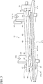
- the cleaning apparatus 10 includes a cleaning chamber 19, a partition wall 93, an intermediate shutter 94, a turn table 87, a cleaning table 31, a clamping device (first clamping device) 51, a clamping device (second clamping device) 151, a lifter 71, a moving device 14, a nozzle 15, an air blowing device 85, and a control device 25.
- the cleaning apparatus 10 may include a turret 13, a pump 18, and an air source 83.
- the cleaning chamber 19 is, for example, box-shaped.
- the cleaning chamber 19 has a drying station 95 at the front and a cleaning station 97 at the rear.
- the nozzle 15 and the moving device 14 are arranged in the cleaning station 97.
- the turn table 87 is arranged across the cleaning station 97 and the drying station 95.
- the turn table 87 includes two regions 87a, 87b and a movable wall 88.
- the movable wall 88 partitions the turn table 87 into two regions 87a, 87b.
- the turn table 87 turns about the turning axis 36 by 180 degrees.
- the turning axis 36 extends in the vertical direction (Z-axis direction) on the boundary between the cleaning station 97 and the drying station 95.
- the regions 87a, 87b are arranged in a 180 degree rotational symmetry about the turning axis 36.
- the turn table 87 positions one of the two regions 87a, 87b at the cleaning station 97 and the other at the drying station 95.
- the movable wall 88 is a flat plate and is fixed to the turn table 87 on a plane passing through the turning axis 36 and perpendicular to the turn table 87.
- the movable wall 88 is connected to the partition wall 93.
- the movable wall 88 turns about the turning axis 36 together with the turn table 87.
- the partition wall 93 is a flat plate and is disposed in the cleaning chamber 19.
- the partition wall 93 partitions the cleaning chamber 19 into the cleaning station 97 and the drying station 95.
- the partition wall 93 passes through the turning axis 36 and extends parallel to the XZ plane.
- the partition wall 93 has a conveyance port 96.
- the intermediate shutter 94 opens and closes the conveyance port 96.
- the intermediate shutter 94 is a sliding door that slides up and down.
- the intermediate shutter 94 contacts the movable wall 88.
- the conveyance port 96 is closed.
- a loading port (not shown) is located at the drying station 95.
- the loading port is disposed, for example, on the front surface or the upper surface of the cleaning apparatus 10.
- the loading shutter (not shown) opens and closes the loading port.
- the loading shutter is, for example, a slide door.
- a pair of clamping devices 51, 151 and a lifter 71 are arranged both in the drying station 95 and the cleaning station 97.
- the clamping device 51 is arranged on the left side and the clamping device 151 is arranged on the right side.
- the clamping device 51 is arranged on the right side and the clamping device 151 is arranged on the left side.
- the lifter 71 is disposed below the cleaning chamber 19.
- the clamping device 51 includes a clamp shaft 59.
- the clamping device 151 includes a clamp shaft 159.
- the clamp shafts 59 and 159 rotate about a drying axis 121.
- the clamp shafts 59 and 159 rotate about a cleaning axis 21.
- the drying axis 121 has the same height as the cleaning axis 21.
- the moving device 14 moves the nozzle 15 relative to the workpiece 3.
- the pump 18 is a liquid pump such as a piston pump, a gear pump, or a centrifugal pump.
- the pump 18 supplies cleaning liquid supplied from a cleaning liquid tank (not shown) to the nozzle 15 via the turret 13.
- the moving device 14 freely moves the turret 13 and the nozzle 15 in the left-right direction (X-axis direction), the front-rear direction (Y-axis direction), and the vertical direction (Z-axis direction) with respect to the cleaning table 31.
- the clamping devices 51, 151 clamp the workpiece 3 in the direction of the cleaning axis 21 and rotate about the cleaning axis 21 in the A-axis direction.
- the turret 13 is provided on the moving device 14.
- the turret 13 has a nozzle rotation axis 16 extending in the Z-axis direction.
- the turret 13 may have a plurality of nozzles 15.
- the turret 13 rotates to select one nozzle 15.
- the turret 13 supplies the cleaning liquid to the selected nozzle 15.
- the moving device 14 or the turret 13 rotates the nozzle 15 about the nozzle rotation axis 16 in the C-axis direction.
- Japanese Patent Nos. 6147623 and 5432943 are known.
- the nozzle 15 is provided in the turret 13.
- the nozzle 15 rotates about the nozzle rotation axis 16 or is positioned in a rotational direction.
- the nozzle 15 is, for example, a lateral nozzle 153 or a flat spray nozzle 155.
- the lateral nozzle 153 has a shaft body 15a and an injection port 15b.
- the injection port 15b is disposed at the distal end portion of the shaft body 15a, and has an axis line 22 perpendicular to the shaft body 15a.
- the injection port 15b injects the high-pressure jet 20 along the axis line 22.
- the air source 83 is, for example, a compressor or a blower.
- the air blowing device 85 includes an air blowing pipe 85a and a plurality of air blowing nozzles 85b.
- the air blowing pipe 85a is disposed, for example, below the front of the drying station 95.
- the air blowing pipe 85a extends in parallel with the cleaning axis 21.
- the plurality of air blowing nozzles 85b are arranged along the air blowing pipe 85a.
- the air blowing nozzle 85b extends from the air blowing pipe 85a toward the drying axis 121.
- the air blowing nozzle 85b is connected to the air source 83 via an air blowing pipe 85a.
- the control device 25 controls the moving device 14, the clamping devices 51 and 151, the lifter 71, the turn table 87, the pump 18, and the air source 91.
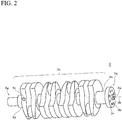
- the workpiece 3 of the present embodiment is, for example, a crankshaft.
- the workpiece 3 includes a flange 3f, a phasing surface 3c, a journal (first journal) 3d, a journal (second journal) 3e, a center hole 3a, a phasing hole 3b, an end 3g, a shaft portion 3h and a center axis 3k.
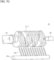
- the flange 3f is located at the left end from the front, and the phasing surface 3c is located at the right end (see FIG. 7H ).
- the first journal 3d is located at the right end, and the second journal 3e is located at the left end.
- the center hole 3a is, for example, conical.
- the center holes 3a are arranged at both ends of the workpiece 3.
- the phasing hole 3b is, for example, a cylindrical hole arranged in the flange 3f away from the center axis 3k and extends along the center axis 3k.
- the phasing surface 3c is, for example, a plane arranged parallel to the center axis 3k.
- the center axis 3k is the rotational center of the workpiece 3.
- the region 87b, the cleaning table 31, the lifter 71, the clamping device 51, and the clamping device 151 will be described in a state that the region 87b is positioned at the cleaning station 97.
- the region 87a and the drying station 95 are substantially the same as the region 87b and the cleaning station 97.
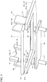
- FIG. 3 is a perspective view of the cleaning table 31 in which the lifter 71 is ascending, as viewed obliquely from the lower front.
- the turn table 87 has a passage opening 89.
- the turn table 87 may include a guide 39, a round pin (second insertion portion) 47.
- the passage opening 89, the guide 39, and the round pin 47 are disposed in the region 87b.
- the passage opening 89 is a rectangular cutout opened rearward.
- the turn table 87 includes a center plate 87c and a projecting portion 87d.
- the projecting portions 87d extend rearward from the left and right end portions of the center plate 87c.
- the pair of guides 39 are respectively disposed at the center of the projecting portion 87d in the front-rear direction.
- the guide 39 is a so-called rough guide.
- the guide 39 extends in the vertical direction and is disposed on the turn table 87.
- the guide 39 has a thin prism shape, and has an inclined surface whose tip portion inclines outward.
- the pair of round pins 47 are respectively disposed at the distal end of the upper surfaces of the projecting portion 87d.
- the round pin 47 includes a cylindrical portion 47a and a tapered portion 47b.
- the tapered portion 47b has a conical shape, and is disposed above the cylindrical portion 47a so as to be continuous with the cylindrical portion 47a.
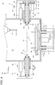
- FIG. 4 is a cross-sectional view of a vertical plane passing through the cleaning axis 21 as viewed from the front.
- the clamping device 51 includes a guide bush (first guide bush) 52, a slide shaft (first slide shaft) 57, a bearing 58, a clamp shaft (first clamp shaft) 59, a motor (clamp shaft motor) 67, a driving gear 66, a driven gear 65, a connecting plate 62, and a clamp cylinder (first clamp driving device) 63.
- the clamping device 51 includes a cover 69, a center pin 61 and a phasing pin 60.
- the guide bush 52 may include a housing 53 and a bush 55.
- the housing 53 has, for example, a hollow cylindrical shape, and is disposed coaxially with the cleaning axis 21.
- the housing 53 is disposed, for example, through a side wall of the cleaning chamber 19.
- the slide shaft 57 has, for example, a hollow cylindrical shape, and is arranged coaxially with the cleaning axis 21.
- the slide shaft 57 slides in the bush 55 and reciprocates in the left-right direction (X-axis direction).
- the slide shaft 57 includes a bearing 58 therein.
- the clamp shaft 59 is cylindrical and is supported by the bearing 58.
- the clamp shaft 59 is arranged coaxially with the cleaning axis 21.
- the center pin 61 and the phasing pin 60 are disposed on the distal end surface of the clamp shaft 59.
- the distal end is an end on the side of the workpiece 3
- the basal end is an end on the side opposite to the workpiece 3.
- the center pin 61 has a conical shape and is disposed coaxially with the cleaning axis 21.
- the phasing pin 60 is disposed at a position away from the cleaning axis 21 and parallel to the cleaning axis 21.
- the center pin 61 and the phasing pin 60 are inserted into the center hole 3a and the phasing hole 3b of the workpiece 3, respectively.
- the center pin 61 and the phasing pin 60 abut against the center hole 3a and the phasing hole 3b.
- the connecting plate 62 is disposed at the basal end of the slide shaft 57.
- the clamp cylinder 63 includes a rod 63a and a cylinder 63b.
- the cylinder 63b is connected to the cleaning chamber 19, and the rod 63a is connected to the connecting plate 62.
- the clamp cylinder 63 is an electric cylinder, and is numerically controlled by the control device 25.
- the clamp cylinder 63 contracts, the slide shaft 57 advances (advances to the left).
- the clamp cylinder 63 extends, the slide shaft 57 retreats (advances to the right).
- the motor 67 is disposed on the connecting plate 62.
- the motor 67 includes an output shaft 67a.
- the motor 67 is, for example, a servo motor.
- the driving gear 66 is fixed to the output shaft 67a.
- the driven gear 65 is fixed to the clamp shaft 59 and meshes with the driving gear 66.
- the driving gear 66 and the driven gear 65 are, for example, spur gears and helical gears.
- the clamp cylinder 63, the connecting plate 62, the driven gear 65, the driving gear 66, and the motor 67 are disposed outside the cleaning chamber 19.
- the cover 69 is a safety cover, and covers the guide bush 52, the slide shaft 57, the driving gear 66, the driven gear 65, the connecting plate 62, the clamp cylinder 63, and the motor 67.
- the clamping device 151 includes a guide bush (second guide bush) 152, a slide shaft (second slide shaft) 157, a bearing 58, a connecting plate 62, and a clamp cylinder (second clamp drive device) 163.
- the clamping device 151 includes a cover 69 and a center pin 61.
- the guide bush 152 has the same structure as the guide bush 52.
- the slide shaft 157 has the same structure as the slide shaft 57.
- the center pin 61 is disposed at the right end of the clamp shaft 159.
- the clamp cylinder 163 has the same structure as the clamp cylinder 63.
- the lifter 71 includes a lift table 49, a lift guide 72, a stem 77, and a lift cylinder 81.
- the lifter 71 may include a cover 74 and a connecting plate 79.
- the lift guide 72 has a housing 73 and a bush 75, and is disposed below the cleaning chamber 19.
- the housing 73 has a hollow cylindrical shape and extends in the vertical direction.
- the bush 75 is disposed inside the housing 73.
- FIG. 5 is a perspective view of the cleaning table 31 in a state in which the lifter 71 is lowered, as seen from a front obliquely lower side.
- the lift table 49 has a round pin (first inserting portion) 42 on its upper surface.
- the lift table 49 is a rectangular flat plate.
- the round pin 42 includes a cylindrical portion 42a and a tapered portion 42b.
- the tapered portion 42b has a conical shape, and is disposed above the cylindrical portion 42a so as to be continuous with the cylindrical portion 42a.
- the lift table 49 overlaps the passage opening 89 when the turn table 87 is positioned, and is smaller than the passage opening 89.
- the stem 77 has, for example, a cylindrical shape. As shown in FIG. 4 , the stem 77 slides in the bush 75 and reciprocates in the vertical direction (Z-axis direction). The upper portion of the stem 77 is connected to the lift table 49. Preferably, the stem 77 is disposed through the bottom surface of the cleaning chamber 19. Preferably, a plurality of stems 77 are disposed.
- the connecting plate 79 connects the lower end of the stem 77.
- the lift cylinder 81 is disposed in the cleaning chamber 19.
- the lift cylinder 81 includes a cylinder 81b and a rod 81a.
- the cylinder 81b is disposed on the bottom surface of the cleaning chamber 19.
- the distal end of the rod 81a is connected to the lift table 49.
- the lift cylinder 81 is an electric cylinder, and is numerically controlled by the control device 25.
- the control device 25 controls the lift cylinder 81.
- the cover 74 is a safety cover and covers the stem 77, the lift guide 72, the lift cylinder 81, and the connecting plate 79.
- the cleaning table 31 includes a top plate 33, a journal block (first journal block) 43, and a journal block (second journal block) 143.
- the cleaning table 31 may include a cylindrical hole (first receiving portion) 41, a support base 35, a cylindrical hole (second receiving portion) 48 (see FIG. 3 ), a guide groove 37, and a phasing block 45.
- the top plate 33 has a rectangular shape. When the lifter 71 is lowered, the top plate 33 is placed on the turn table 87.
- the journal block 43 is a V-block and is disposed on the upper surface of the cleaning table 31.
- the journal block 43 has a V-surface 43a on its center.
- the journal block 143 is substantially to the same as the journal block 43.
- the phasing block 45 is arranged, for example, near the center of the journal block 43.
- the phasing block 45 has a phasing surface 45a.
- the phasing surface 45a is disposed, for example, in parallel with the XZ plane, toward the cleaning axis 21 so as to sandwich the cleaning axis 21.
- the phasing surface 45a abuts the phasing surface 3c of the workpiece 3.
- the support base 35 is, for example, a cylinder.
- the support base 35 is disposed inside the passage opening 89 in plan view, and extends below the top plate 33.
- the lower surface of the support base 35 is a contact surface 35a. When the lifter 71 rises, the contact surface 35a comes into contact with the lift table 49.
- the guide grooves 37 are arranged at the left and right ends of the top plate 33.
- the guide groove 37 is rectangular in plan view and extends in the vertical direction.
- the guide groove 37, at a position matching the guide 39, is disposed to have a gap between the guide groove and the guide 39. When the lifter 71 moves up and down, the guide groove 37 is guided by the guide 39.
- the cylindrical hole 41 is disposed on the lower surface of the cleaning table 31.
- the cylindrical holes 41 are disposed at the left and right end portions, respectively.
- the cylindrical hole 48 is disposed on the lower surface of the cleaning table 31.
- the cylindrical holes 48 are disposed at the left and right ends, respectively.
- the round pin 47 is inserted into the cylindrical hole 48 when the lifter 71 is lowered and the cleaning table 31 is lowered to the turn table 87. At this time, the cylindrical hole 48 and the cylindrical portion 47a come into contact with each other.
- FIG. 6 the flow chart branching to the left shows the cleaning method by the cleaning station 97, and the flow chart branching to the right shows the drying method in the drying station 95.
- the lifter 71 lowers the cleaning table 31 on which the workpiece 3 is mounted onto the turn table 87.
- step S1 the lifter 71 moves down to the retracted position 24.
- the retracted position 24 is a position at which the lift table 49 does not interfere with the turn table 87 when the lift table 49 is positioned below the turn table 87 and the turn table 87 turns.
- the lift table 49 passes through the passage opening 89.
- the retracted position 24 may be the same position regardless of the type of the workpiece 3. For example, it is preferable to set the lowest end to the retracted position 24.
- step S2 the intermediate shutter 94 is opened. As a result, the conveyance port 96 is opened.
- step S3 with the workpiece 3 before cleaning and the cleaning table 31 being carried on, the region 87a in the drying station 95 moves to the cleaning station 97. With the workpiece 3 after cleaning and the cleaning table 31 being carried on, the region 87b in the cleaning station 97 moves to the drying station.
- step S4 the intermediate shutter 94 is closed. This separates the cleaning station 97 from the drying station 95.
- the lifter 71 raises the cleaning table 31 in step S11.
- the lift table 49 passes through the passage opening 89 and supports the cleaning table 31. Subsequently, the lift table 49 rises and the cleaning table 31 reaches a cleaning position 12. In the cleaning position 12, the center axis 3k is aligned with the cleaning axis 21.
- the pump 18 supplies the cleaning liquid to the nozzle 15.
- the nozzle 15 ejects the cleaning liquid.
- the moving device 14 inserts the nozzles 15 between the clamp shafts 59, 159 and the workpiece 3, and causes the jet to collide with the workpiece 3 to clean the both ends 3g of the workpiece 3 in step S12. Thereafter, the moving device 14 moves the nozzle 15 upward to retract.
- the clamp cylinder 63 advances the slide shaft 57.
- the clamp shaft 59 abuts against the first end 3m of the workpiece 3.
- the center pin 61 is inserted into the center hole 3a.
- Phasing pin 60 is inserted into the phasing hole 3b.
- the clamp cylinder 63 presses the clamp shaft 59 against the first end 3m.
- the control device 25 controls the displacement of the clamp shaft 59 based on the position of the first end 3m.
- the clamp cylinder 163 advances the slide shaft 157.
- the clamp shaft 159 abuts against the second end 3n of the workpiece 3.
- the clamp cylinder 163 presses the clamp shaft 159 against the second end 3n.
- the control device 25 controls the displacement of the clamp shaft 159 based on the position of the second end 3n. In this manner, the workpiece 3 is clamped to the clamp shafts 59 and 159 in step S13.
- step S14 the lifter 71 lowers the cleaning table 31 to the retracted position 24. At this time, the lifter 71 places the cleaning table 31 on the turn table 87.
- the moving device 14 moves the nozzles 15 to collide the jet 20 with the workpiece 3, and cleans the shaft portion 3h.
- the control device 25 appropriately rotates the workpiece 3, or positions the workpiece 3 in the rotational direction with the clamp shafts 59, 159 being together in step S15.
- the lifter 71 raises the cleaning table 31 to the cleaning position in step S16.
- the clamp cylinders 63, 163 retract the slide shafts 57, 157, respectively.
- the clamp shafts 59, 159 are spaced apart from the workpiece 3.
- step S17 the workpiece 3 is unclamped and placed on the cleaning table 31.
- step S11 the lifter 71 raises the cleaning table 31 to the drying position.
- the center axis 3k is aligned with the drying axis 121.
- step S13 the clamping devices 51, 151 clamp the workpiece 3.
- step S14 the lifter 71 is lowered, and the cleaning table 31 is placed on the turn table 87. The lifter 71 further lowers to the retracted position.
- step S25 the workpiece is air blown.
- the injection port of the air blowing nozzle 85b faces the workpiece 3.
- the air blowing nozzles 85b eject compressed air or dry air.
- the clamp shafts 59, 159 rotate the workpiece 3 as appropriate.
- step S16 the lifter 71 raises the cleaning table 31 to the drying position.
- step S17 the clamping devices 51, 151 unclamp the workpiece.
- the workpiece 3 is placed on the cleaning table 31.
- step S28 the loading shutter is opened.
- the workpiece 3 in the drying station 95 is unloaded by a conveyance device (not shown) or by an operator.
- the control device 25 controls the height of the cleaning table 31 based on the diameter of the journal of the workpiece 3.
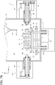
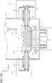
- FIG. 7H is a cross-sectional view of a perpendicular plane passing through the drying axis 121 as viewed from the front.
- step S29 as shown in FIG. 7H , the journal 3d is aligned with the journal block 43, and the journal 3e is aligned with the journal block 143.
- the phasing surface 3c abuts the phasing surface 45a, and the phase of the workpiece 3 is matched with the cleaning table 31.
- step S30 the loading shutter is closed.
- Steps S1 and S2 may be performed simultaneously.
- Step S4 step S11 at the cleaning station 97 and step S11 at the drying station 95 may be performed simultaneously.
- Step S16 and step S28 in the drying station 95 may be performed simultaneously.
- Steps S11, S13, S14, S25, S16, S17, and S28 to S29 in the drying station 95 are performed in parallel with steps S11 to S17 in the cleaning station 97.
- the workpiece 3 is clamped to the clamp shafts 59, 159 about the cleaning axis 21.
- the clamp shafts 59, 159 and the workpiece 3 rotate together.
- the cleaning table 31 is placed on the turn table 87 and is retracted downward. Therefore, the cleaning table 31 does not interfere with the cleaning or air blowing the shaft portion 3h.
- the nozzles 15 can clean the end 3g.
- the lift cylinder 81 is a numerically controlled electric cylinder
- the center axis 3k of the workpiece 3 having different diameters of the journals 3d, 3e can be aligned with the cleaning axis 21 or the drying axis 121.
- the clamp cylinders 63, 163 are numerically controlled electric cylinders, the clamp shafts 59, 159 can abut against the workpiece 3 having different lengths to clamp the workpiece 3 at a predetermined position.
- the lift table 49 can mount the cleaning table 31 at an accurate position.
- the guide 39 guides the guide groove 37, it is possible to suppress the shift of the cleaning table 31 when the cleaning table 31 is moved up and down.
- the turn table 87 can mount the cleaning table 31 at an accurate position. Further, when the turn table 87 turns, the positional deviation of the cleaning table 31 can be suppressed.
- the workpiece 3 is cleaned while being sandwiched and supported by the clamp shafts 59, 159 through the cleaning axis 21. Since the cleaning table 31 is separated from the workpiece 3 when cleaning the shaft portion 3h, the nozzles 15 can easily approach the workpiece 3 and efficiently clean the workpiece 3. Since the workpiece 3 and the cleaning table 31 are separated from each other in the clamped state, and the workpiece 3 is rotated in a state in which the center axis 3k of the workpiece 3 and the cleaning axis 21 are aligned with each other, the inertia can be reduced. It is substantially the same when drying.
- the air blowing nozzle 85b can approach the workpiece 3. Since the air blowing nozzle 85b and the workpiece 3 can approach each other, the blowing effect is enhanced.
- the cleaning chamber 19 includes a cleaning station 97 and a drying station 95, and the turn table 87 turns to convey one workpiece 3 to the cleaning station 97 and another workpiece 3 to the drying station 95. While one workpiece 3 is cleaned in the cleaning station, another workpiece 3 which has been cleaned is air blown, the dried workpiece 3 is unloaded, and the workpiece 3 before cleaning is loaded. Therefore, the cycle time can be shortened.
Landscapes
- Engineering & Computer Science (AREA)
- Mechanical Engineering (AREA)
- General Engineering & Computer Science (AREA)
- Health & Medical Sciences (AREA)
- Life Sciences & Earth Sciences (AREA)
- Molecular Biology (AREA)
- Cleaning By Liquid Or Steam (AREA)
- Cleaning In General (AREA)
Applications Claiming Priority (2)
| Application Number | Priority Date | Filing Date | Title |
|---|---|---|---|
| JP2019126289A JP6842506B2 (ja) | 2019-07-05 | 2019-07-05 | 洗浄機及び洗浄方法 |
| JP2019143283A JP6818825B1 (ja) | 2019-08-02 | 2019-08-02 | 洗浄機及び洗浄方法 |
Publications (2)
| Publication Number | Publication Date |
|---|---|
| EP3760323A1 true EP3760323A1 (fr) | 2021-01-06 |
| EP3760323B1 EP3760323B1 (fr) | 2023-04-12 |
Family
ID=71409084
Family Applications (2)
| Application Number | Title | Priority Date | Filing Date |
|---|---|---|---|
| EP20179783.4A Active EP3760323B1 (fr) | 2019-07-05 | 2020-06-12 | Appareil de nettoyage et procédé de nettoyage |
| EP20179844.4A Active EP3760324B1 (fr) | 2019-07-05 | 2020-06-12 | Appareil de nettoyage |
Family Applications After (1)
| Application Number | Title | Priority Date | Filing Date |
|---|---|---|---|
| EP20179844.4A Active EP3760324B1 (fr) | 2019-07-05 | 2020-06-12 | Appareil de nettoyage |
Country Status (4)
| Country | Link |
|---|---|
| US (2) | US11458511B2 (fr) |
| EP (2) | EP3760323B1 (fr) |
| KR (2) | KR102401174B1 (fr) |
| CN (2) | CN112170376B (fr) |
Cited By (2)
| Publication number | Priority date | Publication date | Assignee | Title |
|---|---|---|---|---|
| CN112893216A (zh) * | 2021-02-03 | 2021-06-04 | 周林 | 一种5g基站机箱的表面除尘装置 |
| US11458511B2 (en) * | 2019-07-05 | 2022-10-04 | Sugino Machine Limited | Cleaning apparatus and cleaning method |
Families Citing this family (26)
| Publication number | Priority date | Publication date | Assignee | Title |
|---|---|---|---|---|
| JP6752346B1 (ja) * | 2019-10-08 | 2020-09-09 | 株式会社スギノマシン | 洗浄機 |
| CN113020112A (zh) * | 2021-03-02 | 2021-06-25 | 清草(广州)百货用品有限公司 | 一种基于计算机内存条的自动清理灰尘装置 |
| CN113020046A (zh) * | 2021-03-09 | 2021-06-25 | 永康市旭茗工贸有限公司 | 一种作用于机械臂轴类零件自动清理润滑保养机构 |
| CN112921621B (zh) * | 2021-04-13 | 2023-05-09 | 宁夏毡匠坊科技发展有限公司 | 一种无纺布清理装置 |
| USD1032127S1 (en) * | 2021-04-23 | 2024-06-18 | Sugino Machine Limited | Spray nozzle for a pressure washing machine |
| CN113441506A (zh) * | 2021-07-02 | 2021-09-28 | 哈尔滨东安华孚机械制造有限公司 | 一种发动机缸盖生产线清洗翻转设备及使用方法 |
| CN113522874B (zh) * | 2021-07-23 | 2022-12-30 | 深圳市诺赛德精密科技有限公司 | 一种电动汽车零部件曲轴机加工后表面清洗机械 |
| CN113787222A (zh) * | 2021-10-11 | 2021-12-14 | 东北大学 | 一种集成原位测量的五轴超声纵扭铣削加工机床 |
| CN114289398B (zh) * | 2021-12-26 | 2023-08-25 | 山东国众机械科技有限公司 | 一种建筑机械保养用齿轮清洗装置 |
| CN114308833A (zh) * | 2022-01-04 | 2022-04-12 | 阳江宏旺实业有限公司 | 具有自适应功能的钢卷生产用清辊器 |
| CN114289394B (zh) * | 2022-01-06 | 2022-12-16 | 江苏伟博机械制造有限公司 | 一种轴类零件加工后的清洗装置 |
| JP7659128B2 (ja) * | 2022-03-30 | 2025-04-08 | 本田技研工業株式会社 | 切削加工機 |
| CN114679846B (zh) * | 2022-04-15 | 2024-08-20 | 珠海格力智能装备有限公司 | 清洁装置及其清洁机构 |
| CN115122106B (zh) * | 2022-07-25 | 2024-02-27 | 厦门德菲尔特新材料有限公司 | 一种中心管的智能加工设备 |
| CN115430629B (zh) * | 2022-08-10 | 2024-04-23 | 威科赛乐微电子股份有限公司 | 一种光罩清洗检测装置及方法 |
| CN115475804B (zh) * | 2022-09-05 | 2025-05-16 | 厦门金鹭特种合金有限公司 | 涂层工装除尘设备及其控制方法 |
| CN115401631B (zh) * | 2022-09-20 | 2024-12-27 | 安徽江淮汽车集团股份有限公司 | 一种用于曲轴孔定位的夹具 |
| CN116673252B (zh) * | 2023-07-18 | 2025-09-09 | 天津德华石油装备制造有限公司 | 螺杆钻具清洗装置 |
| CN117206262A (zh) * | 2023-08-02 | 2023-12-12 | 青田科嘉阀门有限公司 | 一种蜡模模头杂质处理装置 |
| CN118371500B (zh) * | 2024-06-25 | 2024-08-20 | 常州科德水处理成套设备股份有限公司 | 一种用于水管道生产加工的输送设备及方法 |
| CN118912889A (zh) * | 2024-08-23 | 2024-11-08 | 江阴市华士华西冷轧带钢有限公司 | 一种取向硅钢干燥炉 |
| CN119056791A (zh) * | 2024-10-23 | 2024-12-03 | 新余新钢金属制品有限公司 | 钢丝表调液冲洗装置及使用方法 |
| WO2026129053A1 (fr) * | 2024-12-21 | 2026-06-25 | Oilfield Cleaning Services Ltd. | Appareil portatif à base de fluide pour le nettoyage sur site d'outils de champ pétrolifère |
| CN120044435B (zh) * | 2025-04-23 | 2025-07-22 | 山西京缆线缆有限公司 | 一种电缆断芯检测装置 |
| CN121105373B (zh) * | 2025-10-25 | 2026-04-07 | 广东宏盛科技有限公司 | 一种pvc立式主机旋转吹膜机 |
| CN121150402B (zh) * | 2025-11-14 | 2026-01-30 | 宁波帕瓦莱斯智能科技有限公司 | 一种同轴电缸 |
Citations (5)
| Publication number | Priority date | Publication date | Assignee | Title |
|---|---|---|---|---|
| JPS6147623B2 (fr) | 1979-09-21 | 1986-10-20 | Concast Ag | |
| EP1145774A2 (fr) * | 2000-04-13 | 2001-10-17 | Fastems Oy | Station de lavage et de rincage de pièces de travail transférées sur une palette |
| DE102007016120A1 (de) * | 2007-01-17 | 2008-07-24 | Liebherr-Verzahntechnik Gmbh | Verfahren zum Reinigen von vorzugsweise metallischen Werkstücken |
| JP5432943B2 (ja) | 2010-04-05 | 2014-03-05 | 株式会社スギノマシン | 洗浄装置 |
| DE202019105406U1 (de) * | 2018-11-22 | 2019-10-10 | Sugino Machine Limited | Reinigungsvorrichtung |
Family Cites Families (27)
| Publication number | Priority date | Publication date | Assignee | Title |
|---|---|---|---|---|
| US6327994B1 (en) * | 1984-07-19 | 2001-12-11 | Gaudencio A. Labrador | Scavenger energy converter system its new applications and its control systems |
| US4892111A (en) * | 1987-06-22 | 1990-01-09 | Grapar Corporation | Production line part cleaning apparatus |
| US4893642A (en) * | 1989-01-11 | 1990-01-16 | Grapar Corporation | Production line part deburring apparatus |
| SU1741933A1 (ru) * | 1989-06-22 | 1992-06-23 | Б.В.Алексеев | Установка дл мойки коленчатых валов |
| KR950008363U (ko) * | 1993-09-15 | 1995-04-17 | 바렐기 | |
| US20050120715A1 (en) * | 1997-12-23 | 2005-06-09 | Christion School Of Technology Charitable Foundation Trust | Heat energy recapture and recycle and its new applications |
| JP2001327932A (ja) * | 2000-05-23 | 2001-11-27 | Techno Giken Kk | ゴムロール洗浄装置 |
| US7229339B2 (en) * | 2004-07-02 | 2007-06-12 | Novellus Systems, Inc. | CMP apparatus and method |
| JP4636956B2 (ja) * | 2005-07-07 | 2011-02-23 | シブヤマシナリー株式会社 | 内部洗浄装置 |
| DE102007027568B4 (de) * | 2007-06-04 | 2012-05-31 | Armin Zippel | Verfahren zur automatisierten Reinigung von Bauteilen mit komplexer Gestalt der zu reinigenden Bereiche und zugehörige Vorrichtung |
| CN102284442B (zh) * | 2011-07-01 | 2012-12-19 | 天润曲轴股份有限公司 | 一种曲轴表面清洗机 |
| CN103586227A (zh) * | 2012-08-17 | 2014-02-19 | 宜昌英汉超声电气有限公司 | 旋转夹紧清洗装置 |
| JP6008753B2 (ja) * | 2013-02-08 | 2016-10-19 | 株式会社スギノマシン | 洗浄装置 |
| CN103586237A (zh) * | 2013-11-02 | 2014-02-19 | 国家电网公司 | 电缆管道疏通器 |
| JP6253089B2 (ja) * | 2013-12-10 | 2017-12-27 | 株式会社ディスコ | 研削装置 |
| CN105312269B (zh) * | 2014-07-29 | 2017-12-05 | 重庆科本科技有限公司 | 曲轴清洗机 |
| CN109068661A (zh) * | 2016-02-20 | 2018-12-21 | 米拉杰商业发展私人有限公司 | 用于制作扁平食用品的自动机器 |
| JP6475190B2 (ja) * | 2016-05-25 | 2019-02-27 | 株式会社スギノマシン | 傾動装置 |
| CN205904767U (zh) * | 2016-07-05 | 2017-01-25 | 上海丰禾精密机械有限公司 | 双工位旋转台式cnc清洗机 |
| CN206435560U (zh) * | 2016-11-23 | 2017-08-25 | 中船重工双威智能装备有限公司 | 曲轴旋转驱动装置 |
| CN206415370U (zh) * | 2017-01-14 | 2017-08-18 | 东莞市日和自动化设备有限公司 | 一种高压水清洗机 |
| CN109013476B (zh) * | 2018-07-20 | 2021-05-04 | 江苏科技大学 | 一种多规格曲轴的清洗机及曲轴清洗方法 |
| CN109719067B (zh) * | 2018-09-27 | 2024-02-27 | 襄阳福达东康曲轴有限公司 | 曲轴组合式最终清洗设备 |
| CN109663917B (zh) * | 2019-01-24 | 2019-12-27 | 大连理工大学 | 一种电磁感应加热辅助激光增材制造钛基复合材料的装置及方法 |
| US11458511B2 (en) * | 2019-07-05 | 2022-10-04 | Sugino Machine Limited | Cleaning apparatus and cleaning method |
| KR102835295B1 (ko) * | 2020-03-06 | 2025-07-18 | 가부시키가이샤 에바라 세이사꾸쇼 | 연마 장치, 처리 시스템 및 연마 방법 |
| JP7013520B2 (ja) * | 2020-04-24 | 2022-01-31 | 株式会社スギノマシン | 洗浄方法 |
-
2020
- 2020-05-14 US US15/931,882 patent/US11458511B2/en active Active
- 2020-05-25 KR KR1020200062240A patent/KR102401174B1/ko active Active
- 2020-05-27 US US16/884,550 patent/US20210001380A1/en not_active Abandoned
- 2020-05-29 CN CN202010477984.8A patent/CN112170376B/zh active Active
- 2020-06-10 KR KR1020200070179A patent/KR102304677B1/ko active Active
- 2020-06-10 CN CN202010525820.8A patent/CN112170324B/zh active Active
- 2020-06-12 EP EP20179783.4A patent/EP3760323B1/fr active Active
- 2020-06-12 EP EP20179844.4A patent/EP3760324B1/fr active Active
Patent Citations (5)
| Publication number | Priority date | Publication date | Assignee | Title |
|---|---|---|---|---|
| JPS6147623B2 (fr) | 1979-09-21 | 1986-10-20 | Concast Ag | |
| EP1145774A2 (fr) * | 2000-04-13 | 2001-10-17 | Fastems Oy | Station de lavage et de rincage de pièces de travail transférées sur une palette |
| DE102007016120A1 (de) * | 2007-01-17 | 2008-07-24 | Liebherr-Verzahntechnik Gmbh | Verfahren zum Reinigen von vorzugsweise metallischen Werkstücken |
| JP5432943B2 (ja) | 2010-04-05 | 2014-03-05 | 株式会社スギノマシン | 洗浄装置 |
| DE202019105406U1 (de) * | 2018-11-22 | 2019-10-10 | Sugino Machine Limited | Reinigungsvorrichtung |
Cited By (3)
| Publication number | Priority date | Publication date | Assignee | Title |
|---|---|---|---|---|
| US11458511B2 (en) * | 2019-07-05 | 2022-10-04 | Sugino Machine Limited | Cleaning apparatus and cleaning method |
| CN112893216A (zh) * | 2021-02-03 | 2021-06-04 | 周林 | 一种5g基站机箱的表面除尘装置 |
| CN112893216B (zh) * | 2021-02-03 | 2022-05-31 | 河北永基电力器材有限公司 | 一种5g基站机箱的表面除尘装置 |
Also Published As
| Publication number | Publication date |
|---|---|
| CN112170376B (zh) | 2022-09-16 |
| KR20210004827A (ko) | 2021-01-13 |
| CN112170324B (zh) | 2022-06-07 |
| KR20210004834A (ko) | 2021-01-13 |
| US11458511B2 (en) | 2022-10-04 |
| EP3760324B1 (fr) | 2023-11-08 |
| CN112170376A (zh) | 2021-01-05 |
| EP3760324A1 (fr) | 2021-01-06 |
| US20210001380A1 (en) | 2021-01-07 |
| KR102304677B1 (ko) | 2021-09-23 |
| EP3760323B1 (fr) | 2023-04-12 |
| CN112170324A (zh) | 2021-01-05 |
| US20210001379A1 (en) | 2021-01-07 |
| KR102401174B1 (ko) | 2022-05-23 |
Similar Documents
| Publication | Publication Date | Title |
|---|---|---|
| EP3760323B1 (fr) | Appareil de nettoyage et procédé de nettoyage | |
| US9950374B2 (en) | Workpiece clamping apparatus, machine tool and method for working a workpiece | |
| EP3766591B1 (fr) | Appareil de nettoyage | |
| US4563115A (en) | Cutting machine having stock suction means | |
| EP2116325B1 (fr) | Machine-outil | |
| USRE37794E1 (en) | Method and apparatus for machining holes in crankshafts | |
| CN101815597A (zh) | 用于工件的精加工的装置 | |
| KR20010082552A (ko) | 드릴 비트 자동 재연마 장치 및 검증 장치 | |
| KR100405797B1 (ko) | 자동 공구 교환 장치 | |
| JP4842468B2 (ja) | 自動供給排出装置付き工作機械及びその加工方法 | |
| US7422398B2 (en) | Inside machining cutting tool delivery apparatus | |
| JP6818825B1 (ja) | 洗浄機及び洗浄方法 | |
| JP4304469B2 (ja) | ホーニング加工機の工具交換方法及びホーニング加工機。 | |
| JP6842506B2 (ja) | 洗浄機及び洗浄方法 | |
| JP3721386B2 (ja) | ワークの芯出しクランプ装置 | |
| JP3145189B2 (ja) | 縦型パンチプレスのスクラップ処理装置 | |
| CN224168803U (zh) | 一种活塞油孔钻床 | |
| KR200260151Y1 (ko) | 파이프 챔퍼링머신 | |
| JP2003334737A (ja) | ワーク受渡し装置 | |
| JP3681504B2 (ja) | タレットパンチプレスにおける金型認識方法およびタレットパンチプレス | |
| KR102572267B1 (ko) | 머시닝 센터 및 머시닝 센터에서 공작물 블랭크를 가공하기 위한 방법 | |
| KR900005677Y1 (ko) | 가스용기 밸브의 플러그 가공용 브로우칭머신 | |
| JPH0630356Y2 (ja) | 工具交換装置 | |
| JPH068093A (ja) | 多軸工作機械 |
Legal Events
| Date | Code | Title | Description |
|---|---|---|---|
| PUAI | Public reference made under article 153(3) epc to a published international application that has entered the european phase |
Free format text: ORIGINAL CODE: 0009012 |
|
| STAA | Information on the status of an ep patent application or granted ep patent |
Free format text: STATUS: REQUEST FOR EXAMINATION WAS MADE |
|
| 17P | Request for examination filed |
Effective date: 20200612 |
|
| AK | Designated contracting states |
Kind code of ref document: A1 Designated state(s): AL AT BE BG CH CY CZ DE DK EE ES FI FR GB GR HR HU IE IS IT LI LT LU LV MC MK MT NL NO PL PT RO RS SE SI SK SM TR |
|
| AX | Request for extension of the european patent |
Extension state: BA ME |
|
| GRAP | Despatch of communication of intention to grant a patent |
Free format text: ORIGINAL CODE: EPIDOSNIGR1 |
|
| STAA | Information on the status of an ep patent application or granted ep patent |
Free format text: STATUS: GRANT OF PATENT IS INTENDED |
|
| INTG | Intention to grant announced |
Effective date: 20221031 |
|
| RAP3 | Party data changed (applicant data changed or rights of an application transferred) |
Owner name: SUGINO MACHINE LIMITED |
|
| GRAS | Grant fee paid |
Free format text: ORIGINAL CODE: EPIDOSNIGR3 |
|
| GRAA | (expected) grant |
Free format text: ORIGINAL CODE: 0009210 |
|
| STAA | Information on the status of an ep patent application or granted ep patent |
Free format text: STATUS: THE PATENT HAS BEEN GRANTED |
|
| AK | Designated contracting states |
Kind code of ref document: B1 Designated state(s): AL AT BE BG CH CY CZ DE DK EE ES FI FR GB GR HR HU IE IS IT LI LT LU LV MC MK MT NL NO PL PT RO RS SE SI SK SM TR |
|
| REG | Reference to a national code |
Ref country code: GB Ref legal event code: FG4D |
|
| REG | Reference to a national code |
Ref country code: CH Ref legal event code: EP |
|
| REG | Reference to a national code |
Ref country code: DE Ref legal event code: R096 Ref document number: 602020009619 Country of ref document: DE |
|
| REG | Reference to a national code |
Ref country code: IE Ref legal event code: FG4D |
|
| REG | Reference to a national code |
Ref country code: AT Ref legal event code: REF Ref document number: 1559487 Country of ref document: AT Kind code of ref document: T Effective date: 20230515 |
|
| REG | Reference to a national code |
Ref country code: LT Ref legal event code: MG9D |
|
| REG | Reference to a national code |
Ref country code: NL Ref legal event code: MP Effective date: 20230412 |
|
| REG | Reference to a national code |
Ref country code: AT Ref legal event code: MK05 Ref document number: 1559487 Country of ref document: AT Kind code of ref document: T Effective date: 20230412 |
|
| PG25 | Lapsed in a contracting state [announced via postgrant information from national office to epo] |
Ref country code: NL Free format text: LAPSE BECAUSE OF FAILURE TO SUBMIT A TRANSLATION OF THE DESCRIPTION OR TO PAY THE FEE WITHIN THE PRESCRIBED TIME-LIMIT Effective date: 20230412 |
|
| PG25 | Lapsed in a contracting state [announced via postgrant information from national office to epo] |
Ref country code: SE Free format text: LAPSE BECAUSE OF FAILURE TO SUBMIT A TRANSLATION OF THE DESCRIPTION OR TO PAY THE FEE WITHIN THE PRESCRIBED TIME-LIMIT Effective date: 20230412 Ref country code: PT Free format text: LAPSE BECAUSE OF FAILURE TO SUBMIT A TRANSLATION OF THE DESCRIPTION OR TO PAY THE FEE WITHIN THE PRESCRIBED TIME-LIMIT Effective date: 20230814 Ref country code: NO Free format text: LAPSE BECAUSE OF FAILURE TO SUBMIT A TRANSLATION OF THE DESCRIPTION OR TO PAY THE FEE WITHIN THE PRESCRIBED TIME-LIMIT Effective date: 20230712 Ref country code: ES Free format text: LAPSE BECAUSE OF FAILURE TO SUBMIT A TRANSLATION OF THE DESCRIPTION OR TO PAY THE FEE WITHIN THE PRESCRIBED TIME-LIMIT Effective date: 20230412 Ref country code: AT Free format text: LAPSE BECAUSE OF FAILURE TO SUBMIT A TRANSLATION OF THE DESCRIPTION OR TO PAY THE FEE WITHIN THE PRESCRIBED TIME-LIMIT Effective date: 20230412 |
|
| PG25 | Lapsed in a contracting state [announced via postgrant information from national office to epo] |
Ref country code: RS Free format text: LAPSE BECAUSE OF FAILURE TO SUBMIT A TRANSLATION OF THE DESCRIPTION OR TO PAY THE FEE WITHIN THE PRESCRIBED TIME-LIMIT Effective date: 20230412 Ref country code: PL Free format text: LAPSE BECAUSE OF FAILURE TO SUBMIT A TRANSLATION OF THE DESCRIPTION OR TO PAY THE FEE WITHIN THE PRESCRIBED TIME-LIMIT Effective date: 20230412 Ref country code: LV Free format text: LAPSE BECAUSE OF FAILURE TO SUBMIT A TRANSLATION OF THE DESCRIPTION OR TO PAY THE FEE WITHIN THE PRESCRIBED TIME-LIMIT Effective date: 20230412 Ref country code: LT Free format text: LAPSE BECAUSE OF FAILURE TO SUBMIT A TRANSLATION OF THE DESCRIPTION OR TO PAY THE FEE WITHIN THE PRESCRIBED TIME-LIMIT Effective date: 20230412 Ref country code: IS Free format text: LAPSE BECAUSE OF FAILURE TO SUBMIT A TRANSLATION OF THE DESCRIPTION OR TO PAY THE FEE WITHIN THE PRESCRIBED TIME-LIMIT Effective date: 20230812 Ref country code: HR Free format text: LAPSE BECAUSE OF FAILURE TO SUBMIT A TRANSLATION OF THE DESCRIPTION OR TO PAY THE FEE WITHIN THE PRESCRIBED TIME-LIMIT Effective date: 20230412 Ref country code: GR Free format text: LAPSE BECAUSE OF FAILURE TO SUBMIT A TRANSLATION OF THE DESCRIPTION OR TO PAY THE FEE WITHIN THE PRESCRIBED TIME-LIMIT Effective date: 20230713 Ref country code: AL Free format text: LAPSE BECAUSE OF FAILURE TO SUBMIT A TRANSLATION OF THE DESCRIPTION OR TO PAY THE FEE WITHIN THE PRESCRIBED TIME-LIMIT Effective date: 20230412 |
|
| PG25 | Lapsed in a contracting state [announced via postgrant information from national office to epo] |
Ref country code: FI Free format text: LAPSE BECAUSE OF FAILURE TO SUBMIT A TRANSLATION OF THE DESCRIPTION OR TO PAY THE FEE WITHIN THE PRESCRIBED TIME-LIMIT Effective date: 20230412 |
|
| REG | Reference to a national code |
Ref country code: DE Ref legal event code: R097 Ref document number: 602020009619 Country of ref document: DE |
|
| PG25 | Lapsed in a contracting state [announced via postgrant information from national office to epo] |
Ref country code: SK Free format text: LAPSE BECAUSE OF FAILURE TO SUBMIT A TRANSLATION OF THE DESCRIPTION OR TO PAY THE FEE WITHIN THE PRESCRIBED TIME-LIMIT Effective date: 20230412 |
|
| PG25 | Lapsed in a contracting state [announced via postgrant information from national office to epo] |
Ref country code: MC Free format text: LAPSE BECAUSE OF FAILURE TO SUBMIT A TRANSLATION OF THE DESCRIPTION OR TO PAY THE FEE WITHIN THE PRESCRIBED TIME-LIMIT Effective date: 20230412 |
|
| PG25 | Lapsed in a contracting state [announced via postgrant information from national office to epo] |
Ref country code: SM Free format text: LAPSE BECAUSE OF FAILURE TO SUBMIT A TRANSLATION OF THE DESCRIPTION OR TO PAY THE FEE WITHIN THE PRESCRIBED TIME-LIMIT Effective date: 20230412 Ref country code: SK Free format text: LAPSE BECAUSE OF FAILURE TO SUBMIT A TRANSLATION OF THE DESCRIPTION OR TO PAY THE FEE WITHIN THE PRESCRIBED TIME-LIMIT Effective date: 20230412 Ref country code: RO Free format text: LAPSE BECAUSE OF FAILURE TO SUBMIT A TRANSLATION OF THE DESCRIPTION OR TO PAY THE FEE WITHIN THE PRESCRIBED TIME-LIMIT Effective date: 20230412 Ref country code: MC Free format text: LAPSE BECAUSE OF FAILURE TO SUBMIT A TRANSLATION OF THE DESCRIPTION OR TO PAY THE FEE WITHIN THE PRESCRIBED TIME-LIMIT Effective date: 20230412 Ref country code: EE Free format text: LAPSE BECAUSE OF FAILURE TO SUBMIT A TRANSLATION OF THE DESCRIPTION OR TO PAY THE FEE WITHIN THE PRESCRIBED TIME-LIMIT Effective date: 20230412 Ref country code: DK Free format text: LAPSE BECAUSE OF FAILURE TO SUBMIT A TRANSLATION OF THE DESCRIPTION OR TO PAY THE FEE WITHIN THE PRESCRIBED TIME-LIMIT Effective date: 20230412 Ref country code: CZ Free format text: LAPSE BECAUSE OF FAILURE TO SUBMIT A TRANSLATION OF THE DESCRIPTION OR TO PAY THE FEE WITHIN THE PRESCRIBED TIME-LIMIT Effective date: 20230412 |
|
| REG | Reference to a national code |
Ref country code: CH Ref legal event code: PL |
|
| PLBE | No opposition filed within time limit |
Free format text: ORIGINAL CODE: 0009261 |
|
| STAA | Information on the status of an ep patent application or granted ep patent |
Free format text: STATUS: NO OPPOSITION FILED WITHIN TIME LIMIT |
|
| REG | Reference to a national code |
Ref country code: BE Ref legal event code: MM Effective date: 20230630 |
|
| PG25 | Lapsed in a contracting state [announced via postgrant information from national office to epo] |
Ref country code: LU Free format text: LAPSE BECAUSE OF NON-PAYMENT OF DUE FEES Effective date: 20230612 |
|
| 26N | No opposition filed |
Effective date: 20240115 |
|
| REG | Reference to a national code |
Ref country code: IE Ref legal event code: MM4A |
|
| PG25 | Lapsed in a contracting state [announced via postgrant information from national office to epo] |
Ref country code: LU Free format text: LAPSE BECAUSE OF NON-PAYMENT OF DUE FEES Effective date: 20230612 |
|
| PG25 | Lapsed in a contracting state [announced via postgrant information from national office to epo] |
Ref country code: IE Free format text: LAPSE BECAUSE OF NON-PAYMENT OF DUE FEES Effective date: 20230612 |
|
| PG25 | Lapsed in a contracting state [announced via postgrant information from national office to epo] |
Ref country code: IE Free format text: LAPSE BECAUSE OF NON-PAYMENT OF DUE FEES Effective date: 20230612 Ref country code: CH Free format text: LAPSE BECAUSE OF NON-PAYMENT OF DUE FEES Effective date: 20230630 |
|
| PG25 | Lapsed in a contracting state [announced via postgrant information from national office to epo] |
Ref country code: SI Free format text: LAPSE BECAUSE OF FAILURE TO SUBMIT A TRANSLATION OF THE DESCRIPTION OR TO PAY THE FEE WITHIN THE PRESCRIBED TIME-LIMIT Effective date: 20230412 |
|
| PG25 | Lapsed in a contracting state [announced via postgrant information from national office to epo] |
Ref country code: SI Free format text: LAPSE BECAUSE OF FAILURE TO SUBMIT A TRANSLATION OF THE DESCRIPTION OR TO PAY THE FEE WITHIN THE PRESCRIBED TIME-LIMIT Effective date: 20230412 Ref country code: BE Free format text: LAPSE BECAUSE OF NON-PAYMENT OF DUE FEES Effective date: 20230630 |
|
| PG25 | Lapsed in a contracting state [announced via postgrant information from national office to epo] |
Ref country code: BG Free format text: LAPSE BECAUSE OF FAILURE TO SUBMIT A TRANSLATION OF THE DESCRIPTION OR TO PAY THE FEE WITHIN THE PRESCRIBED TIME-LIMIT Effective date: 20230412 |
|
| PG25 | Lapsed in a contracting state [announced via postgrant information from national office to epo] |
Ref country code: BG Free format text: LAPSE BECAUSE OF FAILURE TO SUBMIT A TRANSLATION OF THE DESCRIPTION OR TO PAY THE FEE WITHIN THE PRESCRIBED TIME-LIMIT Effective date: 20230412 |
|
| GBPC | Gb: european patent ceased through non-payment of renewal fee |
Effective date: 20240612 |
|
| PG25 | Lapsed in a contracting state [announced via postgrant information from national office to epo] |
Ref country code: GB Free format text: LAPSE BECAUSE OF NON-PAYMENT OF DUE FEES Effective date: 20240612 |
|
| PG25 | Lapsed in a contracting state [announced via postgrant information from national office to epo] |
Ref country code: CY Free format text: LAPSE BECAUSE OF FAILURE TO SUBMIT A TRANSLATION OF THE DESCRIPTION OR TO PAY THE FEE WITHIN THE PRESCRIBED TIME-LIMIT; INVALID AB INITIO Effective date: 20200612 |
|
| PG25 | Lapsed in a contracting state [announced via postgrant information from national office to epo] |
Ref country code: HU Free format text: LAPSE BECAUSE OF FAILURE TO SUBMIT A TRANSLATION OF THE DESCRIPTION OR TO PAY THE FEE WITHIN THE PRESCRIBED TIME-LIMIT; INVALID AB INITIO Effective date: 20200612 |
|
| PG25 | Lapsed in a contracting state [announced via postgrant information from national office to epo] |
Ref country code: TR Free format text: LAPSE BECAUSE OF FAILURE TO SUBMIT A TRANSLATION OF THE DESCRIPTION OR TO PAY THE FEE WITHIN THE PRESCRIBED TIME-LIMIT Effective date: 20230412 |
|
| PGFP | Annual fee paid to national office [announced via postgrant information from national office to epo] |
Ref country code: IT Payment date: 20260623 Year of fee payment: 7 |
|
| PGFP | Annual fee paid to national office [announced via postgrant information from national office to epo] |
Ref country code: DE Payment date: 20260622 Year of fee payment: 7 |
|
| PGFP | Annual fee paid to national office [announced via postgrant information from national office to epo] |
Ref country code: FR Payment date: 20260626 Year of fee payment: 7 |