EP3760329A1 - Verfahren und vorrichtung zur herstellung eines schlauchnippels - Google Patents
Verfahren und vorrichtung zur herstellung eines schlauchnippels Download PDFInfo
- Publication number
- EP3760329A1 EP3760329A1 EP20178598.7A EP20178598A EP3760329A1 EP 3760329 A1 EP3760329 A1 EP 3760329A1 EP 20178598 A EP20178598 A EP 20178598A EP 3760329 A1 EP3760329 A1 EP 3760329A1
- Authority
- EP
- European Patent Office
- Prior art keywords
- pipe section
- diameter
- predetermined
- compression sleeve
- forming
- Prior art date
- Legal status (The legal status is an assumption and is not a legal conclusion. Google has not performed a legal analysis and makes no representation as to the accuracy of the status listed.)
- Granted
Links
Images
Classifications
-
- B—PERFORMING OPERATIONS; TRANSPORTING
- B21—MECHANICAL METAL-WORKING WITHOUT ESSENTIALLY REMOVING MATERIAL; PUNCHING METAL
- B21D—WORKING OR PROCESSING OF SHEET METAL OR METAL TUBES, RODS OR PROFILES WITHOUT ESSENTIALLY REMOVING MATERIAL; PUNCHING METAL
- B21D17/00—Forming single grooves in sheet metal or tubular or hollow articles
- B21D17/02—Forming single grooves in sheet metal or tubular or hollow articles by pressing
- B21D17/025—Forming single grooves in sheet metal or tubular or hollow articles by pressing by pressing tubes axially
-
- B—PERFORMING OPERATIONS; TRANSPORTING
- B21—MECHANICAL METAL-WORKING WITHOUT ESSENTIALLY REMOVING MATERIAL; PUNCHING METAL
- B21C—MANUFACTURE OF METAL SHEETS, WIRE, RODS, TUBES, PROFILES OR LIKE SEMI-MANUFACTURED PRODUCTS OTHERWISE THAN BY ROLLING; AUXILIARY OPERATIONS USED IN CONNECTION WITH METAL-WORKING WITHOUT ESSENTIALLY REMOVING MATERIAL
- B21C37/00—Manufacture of metal sheets, rods, wire, tubes, profiles or like semi-manufactured products, not otherwise provided for; Manufacture of tubes of special shape
- B21C37/06—Manufacture of metal sheets, rods, wire, tubes, profiles or like semi-manufactured products, not otherwise provided for; Manufacture of tubes of special shape of tubes or metal hoses; Combined procedures for making tubes, e.g. for making multi-wall tubes
- B21C37/15—Making tubes of special shape; Making tube fittings
- B21C37/20—Making helical or similar guides in or on tubes without removing material, e.g. by drawing same over mandrels, by pushing same through dies ; Making tubes with angled walls, ribbed tubes or tubes with decorated walls
- B21C37/205—Making helical or similar guides in or on tubes without removing material, e.g. by drawing same over mandrels, by pushing same through dies ; Making tubes with angled walls, ribbed tubes or tubes with decorated walls with annular guides
-
- B—PERFORMING OPERATIONS; TRANSPORTING
- B21—MECHANICAL METAL-WORKING WITHOUT ESSENTIALLY REMOVING MATERIAL; PUNCHING METAL
- B21C—MANUFACTURE OF METAL SHEETS, WIRE, RODS, TUBES, PROFILES OR LIKE SEMI-MANUFACTURED PRODUCTS OTHERWISE THAN BY ROLLING; AUXILIARY OPERATIONS USED IN CONNECTION WITH METAL-WORKING WITHOUT ESSENTIALLY REMOVING MATERIAL
- B21C37/00—Manufacture of metal sheets, rods, wire, tubes, profiles or like semi-manufactured products, not otherwise provided for; Manufacture of tubes of special shape
- B21C37/06—Manufacture of metal sheets, rods, wire, tubes, profiles or like semi-manufactured products, not otherwise provided for; Manufacture of tubes of special shape of tubes or metal hoses; Combined procedures for making tubes, e.g. for making multi-wall tubes
- B21C37/15—Making tubes of special shape; Making tube fittings
- B21C37/28—Making tube fittings for connecting pipes, e.g. U-pieces
-
- B—PERFORMING OPERATIONS; TRANSPORTING
- B21—MECHANICAL METAL-WORKING WITHOUT ESSENTIALLY REMOVING MATERIAL; PUNCHING METAL
- B21D—WORKING OR PROCESSING OF SHEET METAL OR METAL TUBES, RODS OR PROFILES WITHOUT ESSENTIALLY REMOVING MATERIAL; PUNCHING METAL
- B21D15/00—Corrugating tubes
- B21D15/04—Corrugating tubes transversely, e.g. helically
- B21D15/06—Corrugating tubes transversely, e.g. helically annularly
-
- B—PERFORMING OPERATIONS; TRANSPORTING
- B21—MECHANICAL METAL-WORKING WITHOUT ESSENTIALLY REMOVING MATERIAL; PUNCHING METAL
- B21D—WORKING OR PROCESSING OF SHEET METAL OR METAL TUBES, RODS OR PROFILES WITHOUT ESSENTIALLY REMOVING MATERIAL; PUNCHING METAL
- B21D31/00—Other methods for working sheet metal, metal tubes, metal profiles
- B21D31/06—Deforming sheet metal, tubes or profiles by sequential impacts, e.g. hammering, beating, peen forming
-
- B—PERFORMING OPERATIONS; TRANSPORTING
- B21—MECHANICAL METAL-WORKING WITHOUT ESSENTIALLY REMOVING MATERIAL; PUNCHING METAL
- B21J—FORGING; HAMMERING; PRESSING METAL; RIVETING; FORGE FURNACES
- B21J5/00—Methods for forging, hammering, or pressing; Special equipment or accessories therefor
- B21J5/06—Methods for forging, hammering, or pressing; Special equipment or accessories therefor for performing particular operations
- B21J5/08—Upsetting
-
- F—MECHANICAL ENGINEERING; LIGHTING; HEATING; WEAPONS; BLASTING
- F16—ENGINEERING ELEMENTS AND UNITS; GENERAL MEASURES FOR PRODUCING AND MAINTAINING EFFECTIVE FUNCTIONING OF MACHINES OR INSTALLATIONS; THERMAL INSULATION IN GENERAL
- F16L—PIPES; JOINTS OR FITTINGS FOR PIPES; SUPPORTS FOR PIPES, CABLES OR PROTECTIVE TUBING; MEANS FOR THERMAL INSULATION IN GENERAL
- F16L33/00—Arrangements for connecting hoses to rigid members; Rigid hose-connectors, i.e. single members engaging both hoses
- F16L33/30—Arrangements for connecting hoses to rigid members; Rigid hose-connectors, i.e. single members engaging both hoses comprising parts inside the hoses only
Definitions
- the invention relates to a manufacturing method for profiled hose nipples.
- hose nipples are mostly used to attach a flexible fluid line, for example a rubber hose. Since the fluid line has to be fixed on the hose nipple, such hose nipples have an outer profile, so that, for example, when the fluid line is pressed onto the hose nipple, the outer profile can be pressed into the material of the fluid line, so that a tight, secured against slipping of the fluid line from the hose nipple Connection of the fluid line to the hose nipple is guaranteed.
- the hose nipples can be produced in various ways.
- the nipple profile can be created by turning, grinding, roller burnishing, hammering or pressing.
- prefabricated nipples can also be welded to pipelines, but this is associated with a relatively high level of effort and the risk of leaks.
- Machining has the disadvantage that it can produce chips that have to be carefully removed or the parts must be disposed of. Burnishing and hammering is a non-cutting process, but the result is not always accurate enough. In addition, an associated reduction in diameter is not always tolerable.
- the WO 1986 00 68 13 A1 shows a method in which a pipe end is deformed into an intended profiled shape by a cold-forming diameter reduction.
- a pipe end is deformed into an intended profiled shape by a cold-forming diameter reduction.
- the diameter of the pipeline is reduced in the area of the nipple. This leads to a lower flow rate in the area of the nipple, so that the entire pipeline may have to be designed larger.
- the invention was based on the object of creating a method with the aid of which hose nipples of the type described at the outset can be easily produced while avoiding the disadvantages mentioned and without reducing the diameter.
- This method enables a high-precision production of hose nipples of the generic type.
- a solidification of the material of the pipe section can be achieved.
- High-strength hose nipples can thus be produced by means of the method according to the invention.
- Hose nipples produced in this way have proven their high pressure resistance and tightness with high fatigue strength in corresponding test runs.
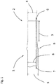
- the Fig. 1 shows a preformed pipe section 1 in a partial longitudinal section.
- the pipe section 1 has an area 3 in which, by previously sliding on a compression sleeve, not shown here, the outer diameter 4 of the pipe section 1 compared to the outer diameter 5 of the remaining pipe section and the wall thickness 6 in section 3 compared to the wall thickness 7 of the remaining pipe section 1 is reduced.
- the inner diameter 8 of the pipe section 1 was initially also reduced in the area 3 by the compression sleeve (not shown) and then expanded again to a predetermined level by calibrating with a forming die (not shown) after the storage space. Due to the interaction of the upsetting sleeve and the forming tool, both not shown, the illustrated geometry of the pipe section 1 in the section 3 with a defined inside diameter 8, outside diameter 4 and wall thickness 6 can be produced with high precision. This provides the prerequisites for a subsequent hammering process.
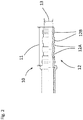
- a fully formed hose nipple 10 is shown, which was produced with the method according to the invention. It is based on a prefabricated blank, as it is in Fig. 1 is shown.
- the hose nipple 10 has approximately with that from the Fig. 1 Already prefabricated area 3 corresponding area 11 has a profile 12 which has profile grooves 12 A and profile webs 12 B. This profile 12 has been generated by a hammering process which is known per se and is not shown here.
- the manufacturing process according to the invention results in a high-precision hose nipple with very good strength, which can be manufactured directly from a pipe section without soldering or welding.
Landscapes
- Engineering & Computer Science (AREA)
- Mechanical Engineering (AREA)
- Forging (AREA)
Abstract
Description
- Die Erfindung betrifft ein Herstellverfahren für profilierte Schlauchnippel.
- Schlauchnippel dienen in der Fluidtechnik meistens zum Aufstecken einer flexiblen Fluidleitung, beispielsweise eines Gummischlauchs. Da die Fluidleitung auf dem Schlauchnippel fixiert werden muss, weisen derartige Schlauchnippel ein Außenprofil auf, sodass beispielsweise bei einer Verpressung der Fluidleitung auf dem Schlauchnippel sich das Außenprofil in das Material der Fluidleitung eindrücken lässt, so das eine dichte, gegen Abrutschen der Fluidleitung vom Schlauchnippel gesicherte Verbindung der Fluidleitung auf dem Schlauchnippel gewährleistet ist.
- Durch immer höhere Anforderungen an die Dichtigkeit der Verbindungen zwischen Schlauch und Nippel ist eine hohe Genauigkeit und Festigkeit der Nippel gefordert.
- Die Herstellung der Schlauchnippel kann auf verschiedene Weise erfolgen. Beispielsweise ist die Erzeugung des Nippelprofils durch Drehen, Schleifen, Rollieren, Hämmern oder Einpressen möglich. Außerdem können vorgefertigte Nippel auch an Rohrleitungen angeschweißt werden, was aber mit relativ hohem Aufwand verbunden ist und die Gefahr von Undichtigkeiten mit sich bringt.
- Die spanende Bearbeitung bringt den Nachteil mit sich, dass dabei Späne entstehen können, die sorgfältig entfernt werden oder die Teile entsorgt werden müssen. Das Rollieren und Hämmern ist zwar ein spanloses Verfahren, das Ergebnis ist jedoch nicht immer genau genug. Außerdem ist eine damit verbundene Durchmesserverringerung nicht immer tolerierbar.
- Die
WO 1986 00 68 13 A1 zeigt ein Verfahren, bei dem ein Rohrleitungsende durch eine kaltumformende Durchmesserreduzierung in eine vorgesehene profilierte Form verformt wird. Neben der Gefahr, dass bei diesem Verfahren Grate entstehen, kommt hier noch nachteilig hinzu, dass dabei der Durchmesser der Rohrleitung im Bereich des Nippels reduziert wird. Dies führt zu einem geringeren Durchfluss im Bereich des Nippels, so dass gegebenenfalls die gesamte Rohrleitung größer ausgelegt werden muss. - Der Erfindung lag die Aufgabe zugrunde, ein Verfahren zu schaffen, mithilfe dessen Schlauchnippel der eingangs geschilderten Art unter Vermeidung der genannten Nachteile und ohne Durchmesserverringerung einfach herstellbar sind.
- Diese Aufgabe wird dadurch gelöst, dass das Verfahren folgende Arbeitsschritte aufweist, nämlich
- Bereitstellung eines Vorwerkzeuges, aufweisend einen Umformstempel eine Stauchhülse und eine Rohrhalterung,
- Einlegen eines Rohrabschnittes in die Rohrhalterung,
- Einführen des Umformstempels in das Innere des Rohrabschnitts,
- Aufschieben der Stauchhülse auf den Rohrabschnitt mit eingeschobenem Umformstempel, wobei die Stauchhülse einen vorbestimmten geringeren Innendurchmesser aufweist, als der Rohrabschnitt, wobei beim Aufschieben der Stauchhülse der Rohrabschnitt einerseits axial gestaucht, andererseits radial im Durchmesser auf ein vorbestimmtes Maß verringert wird, dabei Ausbildung eines Fassungsbundes an dem Rohrabschnitt,
- Zurückziehen des Umformstempels durch den in der Stauchhülse befindlichen Teil des Rohrabschnitts, dabei Aufweitung des Innendurchmessers des Rohrabschnitts um ein vorbestimmtes, durch ein vorgewähltes Verhältnis von Ursprungsinnendurchmesser des Rohrabschnitts und Außendurchmesser des Umformstempels gegebenes Maß, wodurch die Wandstärke des Rohrabschnitts im Bereich der Hülse verringert wird,
- Entnehmen des Rohrabschnitts aus der Stauchhülse,
- Aufschieben des Rohrabschnitts auf einen Stützdorn mit vorbestimmtem Durchmesser,
- Bereitstellung eines Hämmerwerkzeugs und Hämmern des Rohrabschnitts, dabei Ausbildung einer vorbestimmten Außenkontur des Rohrabschnitts,
- Entnehmen des Fertigteils aus dem Werkzeug.
- Dieses Verfahren ermöglicht eine hochpräzise Herstellung von gattungsgemäßen Schlauchnippeln. Durch die Reduzierung der Wandstärke des Rohrabschnitts bei gleichzeitig vorkalibriertem Innen- und Außendurchmesser ist eine Verfestigung des Materials des Rohrabschnitts erreichbar. Damit sind mittels des erfindungsgemäßen Verfahrens hochfeste Schlauchnippel erzeugbar.
- Das gesamte Verfahren ist, bis auf das Entgraten an der Nippelspitze, nahezu spanlos. Auf den kritischen Außenflächen des Nippels sind keine Formgrate vorhanden. Derartig erzeugte Schlauchnippel haben in entsprechenden Testläufen ihre hohe Druckfestigkeit und Dichtigkeit bei hoher Dauerfestigkeit bewiesen.
- Anhand der Zeichnung wird nachstehend ein Beispiel der Erfindung näher erläutert. Es zeigt
-
Fig. 1 einen vorgeformten Rohrabschnitt in einem Teillängsschnitt, -
Fig. 2 einen fertig ausgeformten Schlauchnippel. - Die
Fig. 1 zeigt einen vorgeformten Rohrabschnitt 1 in einem Teillängsschnitt. An seinem ersten Ende 2 weist der Rohrabschnitt 1 einen Bereich 3 auf, bei dem durch ein vorhergehendes Aufschieben einer hier nicht gezeigten Stauchhülse der Außendurchmesser 4 des Rohrabschnitts 1 gegenüber dem Außendurchmesser 5 des restlichen Rohrabschnitts sowie die Wandstärke 6 im Abschnitt 3 gegenüber der Wandstärke 7 des übrigen Rohrabschnitts 1 reduziert ist. - Durch das Aufschieben der nicht gezeigten Hülse ist außerdem ein Fassungsbund 9 angestaucht worden.
- Der Innendurchmesser 8 des Rohrabschnitts 1 wurde im Bereich 3 durch die nicht gezeigte Stauchhülse zunächst ebenfalls reduziert, durch das kalibrieren mit einem nicht gezeigten Umformstempel nach dem Stauraum wieder auf ein vorbestimmtes Maß aufgeweitet. Durch das Zusammenwirken von Stauchhülse und Umformwerkzeugs, beide nicht gezeigt, ist die dargestellte Geometrie des Rohrabschnitts 1 im Abschnitt 3 mit definiertem Innendurchmesser 8, Außendurchmesser 4 und Wandstärke 6 hochpräzise herstellbar. Damit sind die Voraussetzung für einen nachfolgenden Hämmervorgang gegeben.
- In
Fig. 2 ist ein fertig ausgebildeter Schlauchnippel 10 gezeigt, der mit dem erfindungsgemäßen Verfahren hergestellt wurde. Zugrunde liegt ein vorgefertigter Rohling, wie er inFig. 1 dargestellt ist. - Der Schlauchnippel 10 weist in einem etwa mit dem aus der
Fig. 1 bereits vorgefertigten Bereich 3 korrespondierenden Bereich 11 ein Profil 12 auf, welches Profilnuten 12 A und Profilstege 12 B aufweist. Dieses Profil 12 ist durch einen Hämmerprozess erzeugt worden, welcher an sich bekannt und hier nicht dargestellt ist. - Damit beim Hämmern der Innendurchmesser 13 im Bereich 11 nicht unter einen vorgegebenen Wert sinkt, erfolgt der Hämmerprozess auf einem hier nicht gezeigten, in das Innere des Schlauchnippels 10 eingeschobenen Dorn.
- Durch den erfindungsgemäßen Fertigungsprozess entsteht ein hochpräziser Schlauchnippel mit sehr guter Festigkeit, der ohne Löten oder Schweißen direkt aus einem Rohrabschnitt herstellbar ist.
-
- 1
- vorgeformter Rohrabschnitt
- 2
- erstes Ende des vorgeformten Rohrabschnitts 1
- 3
- umgeformter Bereich des Rohrabschnitts 1
- 4
- Außendurchmesser des Rohrabschnitts 1 im Bereich 3
- 5
- Außendurchmesser des Rohrabschnitts 1 außerhalb des Bereichs 3
- 6
- Wandstärke des Rohrabschnitts 1 im Bereich 3
- 7
- Wandstärke des Rohrabschnitts 1 außerhalb des Bereichs 3
- 8
- Innendurchmesser des Rohrabschnitts 1
- 9
- Fassungsbund des Rohrabschnitts 1
- 10
- Schlauchnippel
- 11
- profilierter Bereich des Schlauchnippels 10
- 12
- im Bereich 11 des Schlauchnippels 10
- 12A
- Profilnuten des Profils 12
- 12B
- Profilstege des Profils 12
- 13
- Innendurchmesser des Schlauchnippels im Bereich 11
Claims (1)
- Herstellverfahren für profilierte Schlauchnippel (1, 10), dadurch gekennzeichnet, dass das Verfahren folgende Arbeitsschritte aufweist, nämlich- Bereitstellung eines Vorwerkzeuges, aufweisend einen Umformstempel eine Stauchhülse und eine Rohrhalterung,- Einlegen eines Rohrabschnittes (1) in die Rohrhalterung,- Einführen des Umformstempels in das Innere des Rohrabschnitts (1),- Aufschieben der Stauchhülse auf den Rohrabschnitt (1, 3) mit eingeschobenem Umformstempel, wobei die Stauchhülse einen vorbestimmten geringeren Innendurchmesser (4) aufweist als der Rohrabschnitt (1), wobei beim Aufschieben der Stauchhülse der Rohrabschnitt (1, 3) einerseits axial gestaucht, andererseits radial im Durchmesser auf ein vorbestimmtes Maß (4) verringert wird, dabei Ausbildung eines Fassungsbundes (9) an dem Rohrabschnitt (1),- Zurückziehen des Umformstempels durch den in der Stauchhülse befindlichen Teil (3) des Rohrabschnitts (1), dabei Aufweitung des Innendurchmessers (8) des Rohrabschnitts (3) um ein vorbestimmtes, durch ein vorgewähltes Verhältnis von Ursprungsinnendurchmesser (8) des Rohrabschnitts (1) und Außendurchmesser des Umformstempels gegebenes Maß, wodurch die Wandstärke (6) des Rohrabschnitts (1) im Bereich (3) der Hülse verringert wird,- Entnehmen des Rohrabschnitts (1, 3) aus der Stauchhülse,- Aufschieben des Rohrabschnitts (1, 3) auf einen Stützdorn mit vorbestimmtem Durchmesser,- Bereitstellung eines Hämmerwerkzeugs und Hämmern des Rohrabschnitts (1, 3), dabei Ausbildung einer vorbestimmten Außenkontur (12) des Rohrabschnitts (3),- Entnehmen des Fertigteils (10) aus dem Werkzeug.
Applications Claiming Priority (1)
| Application Number | Priority Date | Filing Date | Title |
|---|---|---|---|
| DE102019209918.1A DE102019209918A1 (de) | 2019-07-05 | 2019-07-05 | Verfahren und Vorrichtung zur Herstellung eines Schlauchnippels |
Publications (2)
| Publication Number | Publication Date |
|---|---|
| EP3760329A1 true EP3760329A1 (de) | 2021-01-06 |
| EP3760329B1 EP3760329B1 (de) | 2024-10-16 |
Family
ID=71069683
Family Applications (1)
| Application Number | Title | Priority Date | Filing Date |
|---|---|---|---|
| EP20178598.7A Active EP3760329B1 (de) | 2019-07-05 | 2020-06-05 | Verfahren zur herstellung eines schlauchnippels |
Country Status (2)
| Country | Link |
|---|---|
| EP (1) | EP3760329B1 (de) |
| DE (1) | DE102019209918A1 (de) |
Citations (7)
| Publication number | Priority date | Publication date | Assignee | Title |
|---|---|---|---|---|
| DE1272866B (de) * | 1966-07-01 | 1968-07-18 | Rheinmetall Gmbh | Vorrichtung zur Erzeugung einer ringfoermigen Falte aus einer Rohrwand |
| FR2332476A1 (fr) * | 1975-11-21 | 1977-06-17 | Chausson Usines Sa | Raccord pour relier une tubulure souple a un embout d'une machine de travail et procede pour sa fabrication |
| US4330142A (en) * | 1980-01-10 | 1982-05-18 | Fayette Tubular Products | Formed hose couplings |
| WO1986006813A1 (fr) | 1985-05-11 | 1986-11-20 | Aeroquip Gmbh | Procede de fabrication d'un embout pour raccords filetes ou a emboitement soumis a des charges hydrauliques |
| DE19941577A1 (de) * | 1999-09-01 | 2001-03-29 | Parker Hannifin Gmbh | Rohrverbindung und Verfahren zu ihrer Herstellung |
| EP2469142A1 (de) * | 2010-12-22 | 2012-06-27 | Viega GmbH & Co. KG | Pressfitting und dessen Verwendung |
| JP2016022490A (ja) * | 2014-07-17 | 2016-02-08 | 横浜ゴム株式会社 | ニップル及びその製造方法並びに継手金具を製造してホースと連結する方法 |
-
2019
- 2019-07-05 DE DE102019209918.1A patent/DE102019209918A1/de active Pending
-
2020
- 2020-06-05 EP EP20178598.7A patent/EP3760329B1/de active Active
Patent Citations (7)
| Publication number | Priority date | Publication date | Assignee | Title |
|---|---|---|---|---|
| DE1272866B (de) * | 1966-07-01 | 1968-07-18 | Rheinmetall Gmbh | Vorrichtung zur Erzeugung einer ringfoermigen Falte aus einer Rohrwand |
| FR2332476A1 (fr) * | 1975-11-21 | 1977-06-17 | Chausson Usines Sa | Raccord pour relier une tubulure souple a un embout d'une machine de travail et procede pour sa fabrication |
| US4330142A (en) * | 1980-01-10 | 1982-05-18 | Fayette Tubular Products | Formed hose couplings |
| WO1986006813A1 (fr) | 1985-05-11 | 1986-11-20 | Aeroquip Gmbh | Procede de fabrication d'un embout pour raccords filetes ou a emboitement soumis a des charges hydrauliques |
| DE19941577A1 (de) * | 1999-09-01 | 2001-03-29 | Parker Hannifin Gmbh | Rohrverbindung und Verfahren zu ihrer Herstellung |
| EP2469142A1 (de) * | 2010-12-22 | 2012-06-27 | Viega GmbH & Co. KG | Pressfitting und dessen Verwendung |
| JP2016022490A (ja) * | 2014-07-17 | 2016-02-08 | 横浜ゴム株式会社 | ニップル及びその製造方法並びに継手金具を製造してホースと連結する方法 |
Also Published As
| Publication number | Publication date |
|---|---|
| EP3760329B1 (de) | 2024-10-16 |
| DE102019209918A1 (de) | 2021-01-07 |
Similar Documents
| Publication | Publication Date | Title |
|---|---|---|
| DE10031989B4 (de) | Verfahren und Vorrichtung zur Herstellung von Pressfittings aus Stahl, insbesondere Edelstahl | |
| DE102008024360B4 (de) | Rohrpresskupplung, insbesondere für Mehrschichtverbundrohre, sowie Verpressungsverfahren | |
| WO2011029687A1 (de) | Rohrverschraubung und verfahren zur herstellung derselben | |
| EP0787047A1 (de) | Verfahren zum anstauchen von rohrenden und vorrichtung zur durchführung des verfahrens | |
| DE10333122A1 (de) | Verfahren zur Herstellung einer Rohrleitung mit einem Verbindungsbereich | |
| WO2015014557A1 (de) | Pressfitting für gewindeanschluss und verfahren zum anbinden eines fittings an einem gewindeanschluss | |
| EP1707861B1 (de) | Fitting und Verfahren zur Herstellung eines Fittings | |
| EP2184525A1 (de) | Rohrverbindung mit einem Rohr und Verfahren zur Herstellung eines Verbindungsabschnitts einer Rohrverbindung | |
| DE102010060686A1 (de) | Verfahren und Komponentensatz zur Herstellung eines rohrförmigen Bauteils, insbesondere einer gebauten Nockenwelle | |
| DE102007042606A1 (de) | Anschlussvorrichtung und Verfahren zum Herstellen einer Anschlussvorrichtung für einen ringgewellten oder schraubengangförmig gewellten Metallschlauch mit Elastomer-Ummantelung | |
| EP2205371B1 (de) | Verfahren zur herstellung von rohr-in-rohr-systemen | |
| EP2725272B1 (de) | Hülse für unlösbare Verbindung, Verfahren zur Herstellung einer Hülse und System mit einer Hülse | |
| EP3760329B1 (de) | Verfahren zur herstellung eines schlauchnippels | |
| DE102020132822B4 (de) | Verfahren zur Herstellung eines inneren Anschlags in einem Rohrbauteil | |
| DE3517163C2 (de) | ||
| EP0926415B1 (de) | Rohrverbindung | |
| DE4004008C1 (de) | ||
| EP1396396A1 (de) | Verfahren zum Herstellen eines Gasgeneratorgehäuseteils, Gasgenerator mit diesem Gehäuseteil sowie Gassackmodul | |
| DE102010044902A1 (de) | Verfahren zum Einbringen einer Hülse, insbesondere einer Gewindehülse in ein Werkstück | |
| EP0922510A1 (de) | Verfahren und Vorrichtung zur Fertigung eines Rohres in einem Rohrboden | |
| DE102005036419B4 (de) | Vorrichtung zur Herstellung ausgebauchter Hohlprofile, insbesondere von Gasgeneratorgehäusen für Airbageinrichtungen | |
| DE102011107450A1 (de) | Vorrichtung und Verfahren zum Umformen eines Rohrs | |
| WO1999011964A1 (de) | Verrohrungsstück und verfahren zur herstellung eines verrohrungsstücks | |
| DE19702719C1 (de) | Verfahren zur Herstellung eines metallischen Rohrverbinders | |
| DE102012110792B4 (de) | Umformverfahren zur Herstellung einer stufenförmigen Querschnittsverjüngung an einem rohrförmigen Werkstück aus Metall |
Legal Events
| Date | Code | Title | Description |
|---|---|---|---|
| PUAI | Public reference made under article 153(3) epc to a published international application that has entered the european phase |
Free format text: ORIGINAL CODE: 0009012 |
|
| STAA | Information on the status of an ep patent application or granted ep patent |
Free format text: STATUS: THE APPLICATION HAS BEEN PUBLISHED |
|
| AK | Designated contracting states |
Kind code of ref document: A1 Designated state(s): AL AT BE BG CH CY CZ DE DK EE ES FI FR GB GR HR HU IE IS IT LI LT LU LV MC MK MT NL NO PL PT RO RS SE SI SK SM TR |
|
| AX | Request for extension of the european patent |
Extension state: BA ME |
|
| STAA | Information on the status of an ep patent application or granted ep patent |
Free format text: STATUS: REQUEST FOR EXAMINATION WAS MADE |
|
| 17P | Request for examination filed |
Effective date: 20210706 |
|
| RBV | Designated contracting states (corrected) |
Designated state(s): AL AT BE BG CH CY CZ DE DK EE ES FI FR GB GR HR HU IE IS IT LI LT LU LV MC MK MT NL NO PL PT RO RS SE SI SK SM TR |
|
| RAP1 | Party data changed (applicant data changed or rights of an application transferred) |
Owner name: CONTITECH TECHNO-CHEMIE GMBH |
|
| GRAP | Despatch of communication of intention to grant a patent |
Free format text: ORIGINAL CODE: EPIDOSNIGR1 |
|
| GRAP | Despatch of communication of intention to grant a patent |
Free format text: ORIGINAL CODE: EPIDOSNIGR1 |
|
| STAA | Information on the status of an ep patent application or granted ep patent |
Free format text: STATUS: GRANT OF PATENT IS INTENDED |
|
| INTG | Intention to grant announced |
Effective date: 20240614 |
|
| RIN1 | Information on inventor provided before grant (corrected) |
Inventor name: GOERZ, MARVIN Inventor name: KOSITZA, EUGEN Inventor name: HUEBL, STEFAN Inventor name: VON HAMMERSTEIN, MATTIAS |
|
| P01 | Opt-out of the competence of the unified patent court (upc) registered |
Free format text: CASE NUMBER: APP_40456/2024 Effective date: 20240708 |
|
| GRAS | Grant fee paid |
Free format text: ORIGINAL CODE: EPIDOSNIGR3 |
|
| GRAA | (expected) grant |
Free format text: ORIGINAL CODE: 0009210 |
|
| STAA | Information on the status of an ep patent application or granted ep patent |
Free format text: STATUS: THE PATENT HAS BEEN GRANTED |
|
| AK | Designated contracting states |
Kind code of ref document: B1 Designated state(s): AL AT BE BG CH CY CZ DE DK EE ES FI FR GB GR HR HU IE IS IT LI LT LU LV MC MK MT NL NO PL PT RO RS SE SI SK SM TR |
|
| REG | Reference to a national code |
Ref country code: GB Ref legal event code: FG4D Free format text: NOT ENGLISH |
|
| REG | Reference to a national code |
Ref country code: CH Ref legal event code: EP Ref country code: DE Ref legal event code: R096 Ref document number: 502020009484 Country of ref document: DE |
|
| REG | Reference to a national code |
Ref country code: IE Ref legal event code: FG4D Free format text: LANGUAGE OF EP DOCUMENT: GERMAN |
|
| REG | Reference to a national code |
Ref country code: LT Ref legal event code: MG9D |
|
| REG | Reference to a national code |
Ref country code: NL Ref legal event code: MP Effective date: 20241016 |
|
| PG25 | Lapsed in a contracting state [announced via postgrant information from national office to epo] |
Ref country code: NL Free format text: LAPSE BECAUSE OF FAILURE TO SUBMIT A TRANSLATION OF THE DESCRIPTION OR TO PAY THE FEE WITHIN THE PRESCRIBED TIME-LIMIT Effective date: 20241016 |
|
| PG25 | Lapsed in a contracting state [announced via postgrant information from national office to epo] |
Ref country code: NL Free format text: LAPSE BECAUSE OF FAILURE TO SUBMIT A TRANSLATION OF THE DESCRIPTION OR TO PAY THE FEE WITHIN THE PRESCRIBED TIME-LIMIT Effective date: 20241016 |
|
| PG25 | Lapsed in a contracting state [announced via postgrant information from national office to epo] |
Ref country code: IS Free format text: LAPSE BECAUSE OF FAILURE TO SUBMIT A TRANSLATION OF THE DESCRIPTION OR TO PAY THE FEE WITHIN THE PRESCRIBED TIME-LIMIT Effective date: 20250216 Ref country code: HR Free format text: LAPSE BECAUSE OF FAILURE TO SUBMIT A TRANSLATION OF THE DESCRIPTION OR TO PAY THE FEE WITHIN THE PRESCRIBED TIME-LIMIT Effective date: 20241016 Ref country code: PT Free format text: LAPSE BECAUSE OF FAILURE TO SUBMIT A TRANSLATION OF THE DESCRIPTION OR TO PAY THE FEE WITHIN THE PRESCRIBED TIME-LIMIT Effective date: 20250217 |
|
| PG25 | Lapsed in a contracting state [announced via postgrant information from national office to epo] |
Ref country code: FI Free format text: LAPSE BECAUSE OF FAILURE TO SUBMIT A TRANSLATION OF THE DESCRIPTION OR TO PAY THE FEE WITHIN THE PRESCRIBED TIME-LIMIT Effective date: 20241016 |
|
| PG25 | Lapsed in a contracting state [announced via postgrant information from national office to epo] |
Ref country code: BG Free format text: LAPSE BECAUSE OF FAILURE TO SUBMIT A TRANSLATION OF THE DESCRIPTION OR TO PAY THE FEE WITHIN THE PRESCRIBED TIME-LIMIT Effective date: 20241016 |
|
| PG25 | Lapsed in a contracting state [announced via postgrant information from national office to epo] |
Ref country code: ES Free format text: LAPSE BECAUSE OF FAILURE TO SUBMIT A TRANSLATION OF THE DESCRIPTION OR TO PAY THE FEE WITHIN THE PRESCRIBED TIME-LIMIT Effective date: 20241016 |
|
| PG25 | Lapsed in a contracting state [announced via postgrant information from national office to epo] |
Ref country code: NO Free format text: LAPSE BECAUSE OF FAILURE TO SUBMIT A TRANSLATION OF THE DESCRIPTION OR TO PAY THE FEE WITHIN THE PRESCRIBED TIME-LIMIT Effective date: 20250116 |
|
| PG25 | Lapsed in a contracting state [announced via postgrant information from national office to epo] |
Ref country code: LV Free format text: LAPSE BECAUSE OF FAILURE TO SUBMIT A TRANSLATION OF THE DESCRIPTION OR TO PAY THE FEE WITHIN THE PRESCRIBED TIME-LIMIT Effective date: 20241016 Ref country code: GR Free format text: LAPSE BECAUSE OF FAILURE TO SUBMIT A TRANSLATION OF THE DESCRIPTION OR TO PAY THE FEE WITHIN THE PRESCRIBED TIME-LIMIT Effective date: 20250117 |
|
| PG25 | Lapsed in a contracting state [announced via postgrant information from national office to epo] |
Ref country code: PL Free format text: LAPSE BECAUSE OF FAILURE TO SUBMIT A TRANSLATION OF THE DESCRIPTION OR TO PAY THE FEE WITHIN THE PRESCRIBED TIME-LIMIT Effective date: 20241016 |
|
| PG25 | Lapsed in a contracting state [announced via postgrant information from national office to epo] |
Ref country code: RS Free format text: LAPSE BECAUSE OF FAILURE TO SUBMIT A TRANSLATION OF THE DESCRIPTION OR TO PAY THE FEE WITHIN THE PRESCRIBED TIME-LIMIT Effective date: 20250116 |
|
| PG25 | Lapsed in a contracting state [announced via postgrant information from national office to epo] |
Ref country code: SM Free format text: LAPSE BECAUSE OF FAILURE TO SUBMIT A TRANSLATION OF THE DESCRIPTION OR TO PAY THE FEE WITHIN THE PRESCRIBED TIME-LIMIT Effective date: 20241016 |
|
| PGFP | Annual fee paid to national office [announced via postgrant information from national office to epo] |
Ref country code: DE Payment date: 20250630 Year of fee payment: 6 |
|
| PG25 | Lapsed in a contracting state [announced via postgrant information from national office to epo] |
Ref country code: DK Free format text: LAPSE BECAUSE OF FAILURE TO SUBMIT A TRANSLATION OF THE DESCRIPTION OR TO PAY THE FEE WITHIN THE PRESCRIBED TIME-LIMIT Effective date: 20241016 |
|
| REG | Reference to a national code |
Ref country code: DE Ref legal event code: R097 Ref document number: 502020009484 Country of ref document: DE |
|
| PG25 | Lapsed in a contracting state [announced via postgrant information from national office to epo] |
Ref country code: EE Free format text: LAPSE BECAUSE OF FAILURE TO SUBMIT A TRANSLATION OF THE DESCRIPTION OR TO PAY THE FEE WITHIN THE PRESCRIBED TIME-LIMIT Effective date: 20241016 |
|
| PGFP | Annual fee paid to national office [announced via postgrant information from national office to epo] |
Ref country code: FR Payment date: 20250626 Year of fee payment: 6 |
|
| PG25 | Lapsed in a contracting state [announced via postgrant information from national office to epo] |
Ref country code: RO Free format text: LAPSE BECAUSE OF FAILURE TO SUBMIT A TRANSLATION OF THE DESCRIPTION OR TO PAY THE FEE WITHIN THE PRESCRIBED TIME-LIMIT Effective date: 20241016 |
|
| PG25 | Lapsed in a contracting state [announced via postgrant information from national office to epo] |
Ref country code: SK Free format text: LAPSE BECAUSE OF FAILURE TO SUBMIT A TRANSLATION OF THE DESCRIPTION OR TO PAY THE FEE WITHIN THE PRESCRIBED TIME-LIMIT Effective date: 20241016 |
|
| PG25 | Lapsed in a contracting state [announced via postgrant information from national office to epo] |
Ref country code: CZ Free format text: LAPSE BECAUSE OF FAILURE TO SUBMIT A TRANSLATION OF THE DESCRIPTION OR TO PAY THE FEE WITHIN THE PRESCRIBED TIME-LIMIT Effective date: 20241016 |
|
| PG25 | Lapsed in a contracting state [announced via postgrant information from national office to epo] |
Ref country code: IT Free format text: LAPSE BECAUSE OF FAILURE TO SUBMIT A TRANSLATION OF THE DESCRIPTION OR TO PAY THE FEE WITHIN THE PRESCRIBED TIME-LIMIT Effective date: 20241016 |
|
| PLBE | No opposition filed within time limit |
Free format text: ORIGINAL CODE: 0009261 |
|
| STAA | Information on the status of an ep patent application or granted ep patent |
Free format text: STATUS: NO OPPOSITION FILED WITHIN TIME LIMIT |
|
| PG25 | Lapsed in a contracting state [announced via postgrant information from national office to epo] |
Ref country code: SE Free format text: LAPSE BECAUSE OF FAILURE TO SUBMIT A TRANSLATION OF THE DESCRIPTION OR TO PAY THE FEE WITHIN THE PRESCRIBED TIME-LIMIT Effective date: 20241016 |
|
| 26N | No opposition filed |
Effective date: 20250717 |
|
| REG | Reference to a national code |
Ref country code: CH Ref legal event code: H13 Free format text: ST27 STATUS EVENT CODE: U-0-0-H10-H13 (AS PROVIDED BY THE NATIONAL OFFICE) Effective date: 20260127 |
|
| PG25 | Lapsed in a contracting state [announced via postgrant information from national office to epo] |
Ref country code: MC Free format text: LAPSE BECAUSE OF FAILURE TO SUBMIT A TRANSLATION OF THE DESCRIPTION OR TO PAY THE FEE WITHIN THE PRESCRIBED TIME-LIMIT Effective date: 20241016 |
|
| PG25 | Lapsed in a contracting state [announced via postgrant information from national office to epo] |
Ref country code: LU Free format text: LAPSE BECAUSE OF NON-PAYMENT OF DUE FEES Effective date: 20250605 |
|
| GBPC | Gb: european patent ceased through non-payment of renewal fee |
Effective date: 20250605 |
|
| REG | Reference to a national code |
Ref country code: BE Ref legal event code: MM Effective date: 20250630 |
|
| PG25 | Lapsed in a contracting state [announced via postgrant information from national office to epo] |
Ref country code: GB Free format text: LAPSE BECAUSE OF NON-PAYMENT OF DUE FEES Effective date: 20250605 |
|
| PG25 | Lapsed in a contracting state [announced via postgrant information from national office to epo] |
Ref country code: IE Free format text: LAPSE BECAUSE OF NON-PAYMENT OF DUE FEES Effective date: 20250605 |
|
| PG25 | Lapsed in a contracting state [announced via postgrant information from national office to epo] |
Ref country code: BE Free format text: LAPSE BECAUSE OF NON-PAYMENT OF DUE FEES Effective date: 20250630 |
|
| PG25 | Lapsed in a contracting state [announced via postgrant information from national office to epo] |
Ref country code: CH Free format text: LAPSE BECAUSE OF NON-PAYMENT OF DUE FEES Effective date: 20250630 |