EP3760332A1 - Procédé de production d'éléments pressés, dispositif de moulage à la presse et plaque métallique pour moulage à la presse - Google Patents
Procédé de production d'éléments pressés, dispositif de moulage à la presse et plaque métallique pour moulage à la presse Download PDFInfo
- Publication number
- EP3760332A1 EP3760332A1 EP19760805.2A EP19760805A EP3760332A1 EP 3760332 A1 EP3760332 A1 EP 3760332A1 EP 19760805 A EP19760805 A EP 19760805A EP 3760332 A1 EP3760332 A1 EP 3760332A1
- Authority
- EP
- European Patent Office
- Prior art keywords
- vertical wall
- press
- wall portion
- shape
- flange portion
- Prior art date
- Legal status (The legal status is an assumption and is not a legal conclusion. Google has not performed a legal analysis and makes no representation as to the accuracy of the status listed.)
- Granted
Links
Images


Classifications
-
- B—PERFORMING OPERATIONS; TRANSPORTING
- B21—MECHANICAL METAL-WORKING WITHOUT ESSENTIALLY REMOVING MATERIAL; PUNCHING METAL
- B21D—WORKING OR PROCESSING OF SHEET METAL OR METAL TUBES, RODS OR PROFILES WITHOUT ESSENTIALLY REMOVING MATERIAL; PUNCHING METAL
- B21D22/00—Shaping without cutting, by stamping, spinning, or deep-drawing
- B21D22/20—Deep-drawing
- B21D22/26—Deep-drawing for making peculiarly, e.g. irregularly, shaped articles
-
- B—PERFORMING OPERATIONS; TRANSPORTING
- B21—MECHANICAL METAL-WORKING WITHOUT ESSENTIALLY REMOVING MATERIAL; PUNCHING METAL
- B21D—WORKING OR PROCESSING OF SHEET METAL OR METAL TUBES, RODS OR PROFILES WITHOUT ESSENTIALLY REMOVING MATERIAL; PUNCHING METAL
- B21D53/00—Making other particular articles
- B21D53/88—Making other particular articles other parts for vehicles, e.g. cowlings, mudguards
-
- B—PERFORMING OPERATIONS; TRANSPORTING
- B21—MECHANICAL METAL-WORKING WITHOUT ESSENTIALLY REMOVING MATERIAL; PUNCHING METAL
- B21D—WORKING OR PROCESSING OF SHEET METAL OR METAL TUBES, RODS OR PROFILES WITHOUT ESSENTIALLY REMOVING MATERIAL; PUNCHING METAL
- B21D19/00—Flanging or other edge treatment, e.g. of tubes
- B21D19/08—Flanging or other edge treatment, e.g. of tubes by single or successive action of pressing tools, e.g. vice jaws
-
- B—PERFORMING OPERATIONS; TRANSPORTING
- B21—MECHANICAL METAL-WORKING WITHOUT ESSENTIALLY REMOVING MATERIAL; PUNCHING METAL
- B21D—WORKING OR PROCESSING OF SHEET METAL OR METAL TUBES, RODS OR PROFILES WITHOUT ESSENTIALLY REMOVING MATERIAL; PUNCHING METAL
- B21D22/00—Shaping without cutting, by stamping, spinning, or deep-drawing
- B21D22/02—Stamping using rigid devices or tools
-
- B—PERFORMING OPERATIONS; TRANSPORTING
- B21—MECHANICAL METAL-WORKING WITHOUT ESSENTIALLY REMOVING MATERIAL; PUNCHING METAL
- B21D—WORKING OR PROCESSING OF SHEET METAL OR METAL TUBES, RODS OR PROFILES WITHOUT ESSENTIALLY REMOVING MATERIAL; PUNCHING METAL
- B21D22/00—Shaping without cutting, by stamping, spinning, or deep-drawing
- B21D22/20—Deep-drawing
-
- B—PERFORMING OPERATIONS; TRANSPORTING
- B21—MECHANICAL METAL-WORKING WITHOUT ESSENTIALLY REMOVING MATERIAL; PUNCHING METAL
- B21D—WORKING OR PROCESSING OF SHEET METAL OR METAL TUBES, RODS OR PROFILES WITHOUT ESSENTIALLY REMOVING MATERIAL; PUNCHING METAL
- B21D24/00—Special deep-drawing arrangements in, or in connection with, presses
Definitions
- the present invention is a technology relating to production of a press-formed component that has a hat-shaped cross-sectional shape including one or more curved portions protruding toward a flange portion (be recessed toward a top sheet portion) along a longitudinal direction as seen in a side view.
- the present invention is a technology suitable for production of a vehicle frame component including a portion curved toward a top sheet portion in a side view.
- the vehicle frame component includes, for example, a top sheet portion and a vertical wall portion and a flange portion respectively continuous in a left-right widthwise direction of the top sheet portion, and is shaped to include a curved portion curved in a longitudinal direction as seen in the side view.
- a crack or a wrinkle may be formed on a part of the component, which can cause a forming defect.
- problems may occur such as lowered dimensional accuracy due to elastic recovery in forming after release.
- a curved portion shape curved in such a manner as to protrude toward the flange portion (be recessed toward the top sheet portion) as seen in a side view, material excess on the top sheet portion side causes a wrinkle, whereas material shortage on the flange portion sides causes cracks.
- PTL 1 describes a technology, which is an example of countermeasures against a spring-back after release in a press-formed component shape including a curved portion so as to protrude toward a flange (be recessed toward a top sheet portion) in a longitudinal direction as seen in a side view.
- PTL 1 proposes a method for increasing rigidity of the entire component by providing a step on vertical wall portions in such a manner that the cross section widens toward the flanges over the entire longitudinal direction.
- the present invention has been made in view of the above problem, and it is an object of the present invention to provide a press forming technology capable of reducing forming defects such as cracks, wrinkles, and lowered dimensional accuracy in a formed component that has a hat-shaped cross-sectional shape including, at least one place, a shape curved in such a manner as to protrude toward a flange portion as seen in a side view.
- the present inventors conducted intensive studies about a press forming method capable of forming, without any cracks and wrinkles, a press-formed component shape that includes a top sheet portion and vertical wall portions and flange portions continuous to the top sheet portion and that includes, at least one place, a shape curved in such a manner as to protrude toward the flange portion (be recessed toward the top sheet portion) as seen in a side view, and also capable of suppressing spring-back.
- the present invention has been made on the basis of such a finding.
- one aspect of the present invention is a method for producing a press-formed component for producing, by press forming a metal sheet, a press-formed component having a press-formed component shape that has a hat-shaped cross-sectional shape including a vertical wall portion and a flange portion on both sides of a widthwise direction of a top sheet portion and that includes, at one or more places along a longitudinal direction of the top sheet portion, a curved portion curved in such a manner as to protrude toward the flange portion as seen in a side view, the method including: a first forming step of press forming the metal sheet into an intermediate formed product in which a wavy shape is formed in regions to be the vertical wall portion and the flange portion; and a second forming step of performing bending on the intermediate formed product to form a ridge line between the top sheet portion and the vertical wall portion and a ridge line between the vertical wall portion and the flange portion in the press-formed component shape, in which the wavy shape includes uneven
- one aspect of the present invention is a press forming device for use in the second forming step of the method for producing a press-formed component according to the above aspect, the press forming device including an upper die including bending blades for bending the metal sheet at ridge line portion positions to perform bending of the vertical wall portion and the flange portion and a lower die including a punch, in which the bending blades are configured to move at an angle set within a range of from 0 degrees to 90 degrees with respect to a pressing direction to perform the bending.
- one aspect of the present invention is a metal sheet for press forming to be formed into a press-formed component shape that has a hat-shaped cross-sectional shape including a vertical wall portion and a flange portion on both sides of a widthwise direction of a top sheet portion and that includes, at one or more places along a longitudinal direction of the top sheet portion, a curved portion curved in such a manner as to protrude toward the flange portion as seen in a side view, the metal sheet including a wavy shape that includes uneven shapes continuous along a longitudinal direction in regions to be the vertical wall portion and the flange portion, an amplitude of the uneven shapes in a sheet thickness direction increasing from a position corresponding to a boundary between the top sheet portion and the vertical wall portion toward a position corresponding to a boundary between the vertical wall portion and the flange portion, in which the wavy shape is set such that a line length difference between a longitudinal line length at the position corresponding to the boundary between the vertical wall portion and the flange portion and
- a formed component having a hat-shaped cross-sectional shape including, at least one place, a shape curved in such a manner as to protrude toward a flange portion as seen in a side view can be produced with reduced forming defects such as cracks, wrinkles, and lowered dimensional accuracy. Then, according to the aspects of the present invention, for example, a spring-back due to a stress difference in the longitudinal direction between the top sheet portion and the flange portions can be suppressed.
- a metal sheet is press formed into a press-formed component shape 1 that has a hat-shaped cross-sectional shape including a top sheet portion 2 and a vertical wall portion 3 and a flange portion 4 respectively continuous on both sides of a left-right widthwise direction of the top sheet portion 2 and that is curved in such a manner as to protrude toward the flange portion (be recessed toward the top sheet portion) along a longitudinal direction as seen in a side view.
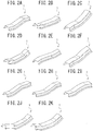
- the present invention is not limited to only the shape entirely curved in the longitudinal direction in such a manner as to protrude toward the flange portion as seen in the side view, as illustrated in FIG. 1 .
- the present invention is also applicable to composite press-formed component shapes including a curved shape protruding toward the top sheet portion and a curved shape recessed toward the top sheet portion and press-formed component shapes including, at two or more places, a curved portion shape protruding toward the flange portions.
- the present invention is also applicable to press-formed component shapes including a linear portion that is continuous to a curved portion curved in such a manner as to protrude toward the flange portion (be recessed toward the top sheet portion) along a longitudinal direction and that extends linearly along the longitudinal direction. Note that the linear portion itself is a portion whose longitudinal line length does not change or hardly changes when bending is performed.
- FIG. 2 illustrates examples of the press-formed component shape 1 to which the present invention can be applied.
- the shape of a metal sheet 10 for use in press forming of the present embodiment is not particularly limited.
- a metal sheet shape that may be employed is, for example, a developed shape of the desired press-formed component shape 1 developed on a plane or a simple rectangular sheet shape. The present description will be given of an example of use of a rectangular metal sheet 10.
- the material of the metal sheet 10 is also not particularly limited. However, the present embodiment is suitably effective on a metal sheet made of a high strength material, particularly, a steel material having a material tensile strength of 590 MPa or more.
- a method for producing a press-formed component according to the present embodiment includes at least a first forming step 9A and a second forming step 9B, as illustrated in FIG. 3 . Since the present embodiment uses the rectangular sheet material as the metal sheet 10, a trimming step is included after the second forming step 9B. When using a sheet material having the developed shape as the metal sheet 10, the trimming step is not necessarily required.
- the method may include a ridge line pre-processing step as processing before the second forming step 9B.
- the ridge line pre-processing step is a step of forming, at least one position of a position 16 corresponding to a ridge line 6 between the top sheet portion 2 and the vertical wall portion 3 and a position 17 corresponding to a ridge line 7 between the vertical wall portion 3 and the flange portion 4, at least one bead shape 20, 21 or crease shape extending in a direction along the corresponding ridge line on the metal sheet 10, as illustrated in FIG. 4 .
- the ridge line pre-processing step may be performed in the first forming step 9A or may be provided as a separate step before or after the first forming step 9A.
- FIG. 4 exemplifies the case where the bead shape 20, 21 is provided
- a crease shape may be provided instead of the bead shape 20, 21.
- the bead shape 20, 21 and a crease shape may be used in combination in such a manner that the bead shape 20, 21 is provided at a part, and the crease shape is provided at the other part.
- the bead shape 20, 21 or a crease shape may be formed on only some of the ridge lines located at the ridge line positions.
- the bead shape or crease shape does not have to be formed over the entire length of one ridge line, and may be formed intermittently along the ridge line.
- a total length of the bead shape 20, 21 is equal to or more than 1/3 of the entire length of the corresponding ridge line.
- a forming step for, for example, restrike may be added as a step subsequent to the second forming step 9B.
- stretch forming is performed on the rectangular metal sheet 10 to produce an intermediate formed product 40.
- the intermediate formed product 40 is a component in which the metal sheet 10 is formed with a wavy shape including uneven shapes continuous along a longitudinal direction in regions to be the vertical wall portion 3 and the flange portion 4 (a vertical wall portion forming position 13 and a flange portion forming position 14), an amplitude of the uneven shapes in a sheet thickness direction increasing from a position corresponding to a boundary between the top sheet portion 2 and the vertical wall portion 3 toward a position corresponding to a boundary 7 between the vertical wall portion 3 and the flange portion 4.
- the wavy shape is set (designed) such that a line length difference between a longitudinal line length at the position 17 corresponding to the boundary 7 between the vertical wall portion 3 and the flange portion 4 and a longitudinal line length at the boundary (the ridge line 7) between the vertical wall portion 3 and the flange portion 4 in the press-formed component shape 1 is equal to or less than 10% of the longitudinal line length at the boundary between the vertical wall portion 3 and the flange portion 4 in the press-formed component shape 1.
- a magnitude of the amplitude or the number of waves formed by unevenness is adjusted to secure an increase in the line length.
- the present embodiment exemplifies a case where the wavy shape is formed on entire surfaces of the regions of the vertical wall portion forming position 13 and the flange portion forming position 14, the wavy shape may be formed on only a partial region in the longitudinal direction. However, as a longitudinal length of the region that is formed with the wavy shape is shorter, it is necessary to make the amplitude higher and make a wave pitch shorter. Thus, the wavy shape is preferably provided within a range of equal to or more than 2/3 of a longitudinal length of the metal sheet 10. Additionally, it is unnecessary to equalize amplitude heights of respective uneven portions and intervals of the waves. However, equalizing the amplitude heights of the respective uneven portions and the intervals of the waves facilitates formation of a die for the wavy shape, and the like.
- the present embodiment exemplifies a case where a sheet that is used as the metal sheet 10 to be formed in the first forming step 9A is the metal sheet 10 that has the same longitudinal length as a longitudinal length of the top sheet portion 2 in the desired press-formed component shape 1.
- the production method of the present embodiment is applicable even when the longitudinal length of the metal sheet 10 is different from the longitudinal length of the top sheet portion 2 in the desired press-formed component shape 1.
- a longitudinal line length L1 of the top sheet portion 2 in the press-formed component shape 1 is calculated by the following expression (1).
- a height of the vertical wall in the press-formed component shape 1 is defined as H (mm)
- a longitudinal curvature radius of the top sheet portion 2 is defined as R (mm)
- a longitudinal bending angle of the curved portion as seen in a side view is defined as ⁇ (degree).
- L 1 2 ⁇ R ⁇ ⁇ / 360
- the present embodiment designs (sets) the shape (wavy shape) of the intermediate formed product 40 in the first forming step 9A, which is required to secure the line length ⁇ L on the flange portion 4 side.
- the method for forming the wavy shape is not limited to the following design method.
- the wavy shape may be designed by any other method than can design the wavy shape in such a manner that the line length difference between the longitudinal line length at the position 17 corresponding to the boundary 7 between the vertical wall portion 3 and the flange portion 4 in the intermediate formed product 40 and the longitudinal line length at the boundary 7 between the vertical wall portion 3 and the flange portion 4 in the press-formed component shape 1 is equal to or less than 10% of the longitudinal line length at the boundary 7 between the vertical wall portion 3 and the flange portion 4 in the press-formed component shape 1.
- a waveform formed by the uneven shapes preferably has a contour shape that does not include a portion with steep curvature, where curvature changes steeply. Additionally, the contour shape does not have to be formed by only a curve, and may partially include a linear portion.
- a surface of the rectangular metal sheet 10 to be press formed is virtually divided into regions of a top sheet portion forming position 12, the vertical wall portion forming position 13, and the flange portion forming position 14, as illustrated in FIG. 5 .
- the present embodiment sets the longitudinal length of the metal sheet 10 to a length equal to the length of the top sheet portion 2 in the desired press-formed component shape 1.
- the top sheet portion forming position 12 there is no material excess nor shortage on the top sheet portion forming position 12, so that it is unnecessary to provide a projection shape for securing the line length.
- the line length along the longitudinal direction gradually increases from the boundary 6 with the top sheet portion 2 toward the boundary 7 with the flange portion 4 by forming the flat-sheet shaped metal sheet 10 into the desired press-formed component shape 1.
- the present embodiment has been considered to provide, to the metal sheet, the shape such that the longitudinal line length gradually increases from the boundary 6 between the top sheet portion 2 and the vertical wall portion 3 toward the boundary 7 between the vertical wall portion 3 and the flange portion 4, i.e., along the widthwise direction, in the intermediate formed product 40.
- the longitudinal line length at the position 17 to be the boundary 7 between the vertical wall portion 3 and the flange portion 4 is designed to become longer than the line length of the top sheet portion 2 by the above-mentioned ⁇ L.
- the line length difference between the longitudinal line length at the position 17 to be the boundary 7 between the vertical wall portion 3 and the flange portion 4 and the longitudinal line length at the boundary 7 between the vertical wall portion 3 and the flange portion 4 in the press-formed component shape 1 is set to equal to or less than 10%, and preferably equal to or less than 5%, of the longitudinal line length at the boundary 7 between the vertical wall portion 3 and the flange portion 4 in the press-formed component shape 1.
- the present embodiment provides a wavy shape formed by repeated uneven portions such that amplitude is the largest at the flange portion forming position 14 to the regions of the vertical wall portion forming position 13 and the flange portion forming position 14.
- the present design is made in such a manner that the required line length ⁇ L is secured by the wavy shape including a plurality of uneven portions along the longitudinal direction at the position 17 to be the boundary 7 between the vertical wall portion 3 and the flange portion 4.
- FIG. 5 illustrates and describes only a front-side region, but even a rear-side region is similarly provided with the wavy shape to secure the line length. Additionally, intervals for providing the control points 30 do not necessarily have to be set to equal intervals.
- a length between adjacent control points 30 is equal to or more than 10% of a component length to arrange the plurality of control points 30.
- the control points 30 at even-numbered positions or odd-numbered positions along the longitudinal direction are displaced in the sheet thickness direction.
- every other one of the control points 30 is displaced in the sheet thickness direction of the metal sheet 10.
- this example exemplifies a case where directions of displacement of the control points to be displaced are alternately displaced in opposite directions, the directions of displacement of the control points to be displaced may be all the same.
- all of the 2n + 1 pieces of the control points 30 are smoothly connected by a spline curve to create a line 31.
- each amount of the displacement may be different.
- the amount of the displacement may be set to larger as being closer to a center of the curved portion.
- the amplitudes of the uneven portions are set to constant, for example, toward an outer edge, i.e., along the widthwise direction.
- a surface shape of the wavy shape is designed by a surface that smoothly connects the line 31 created by the above spline curve and the position 16 to be the boundary 6 between the top sheet portion 2 and the vertical wall portion 3 in the widthwise direction.
- wave amplitude is zero at the boundary 6 between the top sheet portion 2 and the vertical wall portion 3.
- a wavy shape such that the amplitude of the uneven shapes in the sheet thickness direction increases from the position corresponding to the boundary between the top sheet portion 2 and the vertical wall portion 3 toward the position corresponding to the boundary between the vertical wall portion 3 and the flange portion 4.
- the direction from the position corresponding to the boundary between the top sheet portion 2 and the vertical wall portion 3 toward the position corresponding to the boundary between the vertical wall portion 3 and the flange portion 4 may be a widthwise direction of the top sheet portion forming position 12 or a direction inclined in the longitudinal direction by a previously set angle with respect to the widthwise direction.
- the direction may be any direction that intersects the vertical wall portion forming position 13 in the widthwise direction.
- FIG. 6 when creating three uneven shapes (a waveform shape), seven control points 30 are set. While end points of the control points 30 are fixed, every other control point 30 is displaced in the sheet thickness direction by a constant distance to determine the uneven shapes (the waveform shape) at the boundary between the vertical wall portion forming position 13 and the flange portion forming position 14.
- FIG. 7 illustrates a shape of the intermediate formed product 40 designed under the above conditions.
- the wavy shape may have a shape such that the directions of the uneven portions are reversed, a shape such that the uneven shapes are shifted by a half cycle, a shape formed by only protruding shapes or recessed shapes, a shape such that the numbers of the uneven portions are changed, or a shape such that amplitudes of the uneven shapes, respectively, are changed. It is sufficient that the wavy shape has a shape that can secure the line length ⁇ L.
- FIG. 9 illustrates a die for forming the intermediate formed product 40 designed as above.
- the die for use in the first forming step 9A is, for example, a die including an upper die formed by a die 50 and a lower die formed by a punch 52 and a blank holder 51 configured to pinch the portion to be the top sheet portion 2 of the desired press-formed component shape 1 together with the die 50.
- the upper die is further lowered, and the die 50 and the punch 52 stretch form the uneven shapes formed by the wavy shape designed above on the vertical wall portion forming position 13 and the flange portion forming position 14.
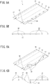
- the second forming step 9B is a step of performing bending on the intermediate formed product 40 formed in the first forming step 9A to form the ridge line 6 between the top sheet portion 2 and the vertical wall portion 3 and the ridge line 7 between the vertical wall 3 portion and the flange portion 4 in the desired press-formed component shape 1, thereby forming the intermediate formed product 40 into the desired press-formed component shape 1.
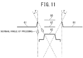
- the second forming step 9B uses a bending die, for example, as illustrated in FIG. 10 , that includes an upper die formed by a die 60 and bending blades 61 configured to perform bending at ridge line portion positions and a lower die formed by a punch 63.
- a bending die for example, as illustrated in FIG. 10 , that includes an upper die formed by a die 60 and bending blades 61 configured to perform bending at ridge line portion positions and a lower die formed by a punch 63.
- the top sheet portion forming position 12 of the metal sheet 10 is pinched by the punch and the die, and in this state, the bending blades 61 on left and right are moved down to a forming bottom dead center toward the punch to perform bending of the vertical wall portions 3 and the vertical wall portions 3.
- the bending blades 61 are preferably configured to perform the forming by moving at an angle ⁇ ranging from 0 degrees to 90 degrees, preferably an angle ⁇ ranging from 0 degrees to 45 degrees, and more preferably an angle ⁇ ranging from 5 degrees to 40 degrees, with respect to a normal angle of pressing, toward a direction away from the punch 63.
- This structure can improve formability in processing by normal bending.
- shape parameters for defining the component shape 1 were set as follows:
- the metal sheet 10 for use in forming was set such that the longitudinal length thereof was equal to the longitudinal length of the top sheet portion 2 in the desired press-formed component shape 1. Specifically, on the basis of the above expression (1), the longitudinal length of the metal sheet 10 was set to 523.6 mm. Additionally, the width thereof was set to about 260 mm.
- a forming analysis of the metal sheet 10 was performed by using the die illustrated in FIG. 9 to obtain the intermediate formed product 40.
- a blank holding force of 50 ton was applied.
- the bending blades 61 for bending ridge lines used a cam mechanism for bending at an angle inclined by 30 degrees with respect to a pressing direction to perform the forming. Additionally, in this case, a pad pressure of 5 ton was applied.
- a forming analysis using a restrike die as illustrated in FIG. 12 was performed as a third forming step after the second forming step 9B.
- the restrike die includes an upper die formed by a die 70 and a lower die formed by a punch 71, and provides a chamfered shape of about C12 to bending portions adjacent to the top sheet portion 2 to suppress the opening of the cross section.
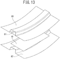
- FIG. 13 illustrates a pad bending die used in this case.
- the pad bending die includes an upper die formed by a die 80 and a pad 81 and a lower die formed by a punch. It is a forming method that bends ridge lines while lowering the upper die and pinching the top sheet portion forming position 12 by the pad 81 and the punch 82.
- the pad pressure was 5 ton.
- the forming analyses were performed under the above conditions to calculate a formability evaluation distribution at a forming bottom dead center in the conventional pad bending and the method based on the present invention, respectively.
- the conventional bending caused material excess on the top sheet portion 2 of the press-formed component shape 1, which was therefore evaluated as causing wrinkling tendency, as illustrated in FIG. 14 . Additionally, cracking tendency was also recognized near both ends of bending ridge lines adjacent to the top sheet portion 2.
- the method based on the present invention enabled forming without causing any wrinkle tendency on the top sheet portion 2 and any cracking tendency, as illustrated in FIG. 15 .
- the method based on the present invention significantly reduced sheet thickness center stress difference in the longitudinal direction between the top sheet portion 2 and the flange surface, whereby it was confirmed that a spring-back such that the end portions in the longitudinal direction are lifted was significantly suppressed as compared to the component formed by the conventional pad bending.
- Example based on the present invention has been the case where the third forming step is included, it has been confirmed that even without the third forming step, forming can be performed without causing any wrinkle tendency on the top sheet portion 2 and any cracking tendency, and the deviation amount from the desired press-formed component shape 1 after release is also small as compared to forming by the conventional bending.
Landscapes
- Engineering & Computer Science (AREA)
- Mechanical Engineering (AREA)
- Shaping Metal By Deep-Drawing, Or The Like (AREA)
Applications Claiming Priority (2)
| Application Number | Priority Date | Filing Date | Title |
|---|---|---|---|
| JP2018034571 | 2018-02-28 | ||
| PCT/JP2019/006553 WO2019167793A1 (fr) | 2018-02-28 | 2019-02-21 | Procédé de production d'éléments pressés, dispositif de moulage à la presse et plaque métallique pour moulage à la presse |
Publications (3)
| Publication Number | Publication Date |
|---|---|
| EP3760332A1 true EP3760332A1 (fr) | 2021-01-06 |
| EP3760332A4 EP3760332A4 (fr) | 2021-04-14 |
| EP3760332B1 EP3760332B1 (fr) | 2025-09-17 |
Family
ID=67805727
Family Applications (1)
| Application Number | Title | Priority Date | Filing Date |
|---|---|---|---|
| EP19760805.2A Active EP3760332B1 (fr) | 2018-02-28 | 2019-02-21 | Procédé de production d'éléments pressés, dispositif de moulage à la presse et plaque métallique pour moulage à la presse |
Country Status (3)
| Country | Link |
|---|---|
| US (1) | US11712729B2 (fr) |
| EP (1) | EP3760332B1 (fr) |
| WO (1) | WO2019167793A1 (fr) |
Families Citing this family (8)
| Publication number | Priority date | Publication date | Assignee | Title |
|---|---|---|---|---|
| KR102819808B1 (ko) * | 2020-06-15 | 2025-06-16 | 삼성디스플레이 주식회사 | 윈도우 성형 장치 및 이를 이용한 윈도우 성형 방법 |
| JP7392746B2 (ja) * | 2022-01-14 | 2023-12-06 | Jfeスチール株式会社 | プレス成形解析方法、プレス成形解析装置及びプレス成形解析プログラム |
| US20250044082A1 (en) * | 2022-01-14 | 2025-02-06 | Jfe Steel Corporation | Press forming analysis method, press forming analysis apparatus, and press forming analysis program |
| WO2023135914A1 (fr) * | 2022-01-17 | 2023-07-20 | Jfeスチール株式会社 | Procédé d'analyse de formage à la presse, dispositif d'analyse de formage à la presse et programme d'analyse de formage à la presse |
| JP7392747B2 (ja) * | 2022-01-17 | 2023-12-06 | Jfeスチール株式会社 | プレス成形解析方法、プレス成形解析装置及びプレス成形解析プログラム |
| JP7416106B2 (ja) * | 2022-01-21 | 2024-01-17 | Jfeスチール株式会社 | プレス成形解析の解析精度評価方法 |
| KR20240121312A (ko) * | 2022-01-21 | 2024-08-08 | 제이에프이 스틸 가부시키가이샤 | 프레스 성형 해석의 해석 정밀도 평가 방법 |
| WO2025083945A1 (fr) * | 2023-10-16 | 2025-04-24 | Jfeスチール株式会社 | Procédé de fabrication de produit formé à la presse, produit formé à la presse et procédé de formage à la presse |
Family Cites Families (13)
| Publication number | Priority date | Publication date | Assignee | Title |
|---|---|---|---|---|
| JP4090028B2 (ja) * | 2002-11-26 | 2008-05-28 | 日新製鋼株式会社 | 薄鋼板のプレス成形用金型装置 |
| JP4021793B2 (ja) | 2003-04-16 | 2007-12-12 | 新日本製鐵株式会社 | 形状凍結性に優れたハット型成形部品のプレス成形方法 |
| JP4367543B2 (ja) | 2007-09-21 | 2009-11-18 | トヨタ自動車株式会社 | 車体構造材用成形品 |
| JP2009241109A (ja) | 2008-03-31 | 2009-10-22 | Kobe Steel Ltd | チャンネル部材の曲げ成形方法 |
| JP5380890B2 (ja) * | 2008-04-15 | 2014-01-08 | 新日鐵住金株式会社 | 形状凍結性に優れたプレス成形方法およびその装置 |
| CN202861089U (zh) | 2012-09-05 | 2013-04-10 | 成都中弘轨道交通环保产业股份有限公司 | 密盲孔板冲压成型装置 |
| WO2014106931A1 (fr) | 2013-01-07 | 2014-07-10 | 新日鐵住金株式会社 | Procédé de production d'un article moulé sous pression |
| DE102013011951A1 (de) | 2013-07-18 | 2015-01-22 | GM Global Technology Operations LLC (n. d. Ges. d. Staates Delaware) | Verfahren zum Fertigen von Kraftfahrzeug-Karosserieteilen |
| KR20170080681A (ko) | 2014-11-12 | 2017-07-10 | 신닛테츠스미킨 카부시키카이샤 | 프레스 성형품의 제조 방법 및 제조 장치 |
| MX375100B (es) | 2016-03-28 | 2025-03-06 | Nippon Steel Corp | Método para producir un producto formado por prensado. |
| KR20190015465A (ko) * | 2016-07-15 | 2019-02-13 | 제이에프이 스틸 가부시키가이샤 | 프레스 성형용 금속판 및 그 제조 방법, 및 프레스품 제조 방법 |
| MX2019001610A (es) | 2016-08-09 | 2019-05-15 | Jfe Steel Corp | Metodo para fabricar un articulo formado a presion. |
| JP6761701B2 (ja) | 2016-08-30 | 2020-09-30 | 株式会社イノアックコーポレーション | 吸気ダクト |
-
2019
- 2019-02-21 EP EP19760805.2A patent/EP3760332B1/fr active Active
- 2019-02-21 WO PCT/JP2019/006553 patent/WO2019167793A1/fr not_active Ceased
- 2019-02-21 US US16/975,601 patent/US11712729B2/en active Active
Also Published As
| Publication number | Publication date |
|---|---|
| US11712729B2 (en) | 2023-08-01 |
| WO2019167793A1 (fr) | 2019-09-06 |
| US20200398328A1 (en) | 2020-12-24 |
| EP3760332A4 (fr) | 2021-04-14 |
| EP3760332B1 (fr) | 2025-09-17 |
Similar Documents
| Publication | Publication Date | Title |
|---|---|---|
| US11712729B2 (en) | Production method for pressed components, press forming device, and metal sheet for press forming | |
| EP3760330B1 (fr) | Plaque métallique pour moulage à la presse, dispositif de moulage à la presse et procédé de production pour un élément pressé | |
| US11628486B2 (en) | Production method for pressed components, press forming device, and metal sheet for press forming | |
| US9211579B2 (en) | Method of producing L-shaped product | |
| KR102463643B1 (ko) | 프레스 부품의 제조 방법 | |
| KR102356422B1 (ko) | 프레스 부품의 제조 방법, 프레스 성형 장치 및, 프레스 성형용의 금속판 | |
| KR102220417B1 (ko) | 프레스 성형품의 제조 방법 및 제조 장치 | |
| JP6330930B1 (ja) | プレス成形方法 | |
| US11951526B2 (en) | Press-formed product manufacturing method and forming die | |
| JP6156608B1 (ja) | 伸びフランジ成形部品の製造方法 | |
| JP5917952B2 (ja) | プレス成形装置 | |
| JP6015784B2 (ja) | 伸びフランジ成形部品の製造方法 | |
| EP3778053A1 (fr) | Procédé de conception pour article moulé à la presse, matrice de moulage à la presse, article moulé à la presse et procédé de production d'article moulé à la presse | |
| CN105848801A (zh) | 冲压成型方法以及冲压成型部件的制造方法 | |
| JP6319382B2 (ja) | 伸びフランジ成形部品の製造方法 | |
| JP6319383B2 (ja) | 伸びフランジ成形部品の製造方法 | |
| JP2019098376A (ja) | プレス成形品の製造方法 | |
| EP4578566A1 (fr) | Procédé de fabrication et flan pour produit formé à la presse | |
| JP2020069534A (ja) | プレス部品の製造方法及び下金型の設計方法 |
Legal Events
| Date | Code | Title | Description |
|---|---|---|---|
| STAA | Information on the status of an ep patent application or granted ep patent |
Free format text: STATUS: THE INTERNATIONAL PUBLICATION HAS BEEN MADE |
|
| PUAI | Public reference made under article 153(3) epc to a published international application that has entered the european phase |
Free format text: ORIGINAL CODE: 0009012 |
|
| STAA | Information on the status of an ep patent application or granted ep patent |
Free format text: STATUS: REQUEST FOR EXAMINATION WAS MADE |
|
| 17P | Request for examination filed |
Effective date: 20200827 |
|
| AK | Designated contracting states |
Kind code of ref document: A1 Designated state(s): AL AT BE BG CH CY CZ DE DK EE ES FI FR GB GR HR HU IE IS IT LI LT LU LV MC MK MT NL NO PL PT RO RS SE SI SK SM TR |
|
| AX | Request for extension of the european patent |
Extension state: BA ME |
|
| REG | Reference to a national code |
Ref country code: DE Ref legal event code: R079 Free format text: PREVIOUS MAIN CLASS: B21D0022260000 Ipc: B21D0022200000 Ref country code: DE Ref legal event code: R079 Ref document number: 602019075840 Country of ref document: DE Free format text: PREVIOUS MAIN CLASS: B21D0022260000 Ipc: B21D0022200000 |
|
| A4 | Supplementary search report drawn up and despatched |
Effective date: 20210317 |
|
| RIC1 | Information provided on ipc code assigned before grant |
Ipc: B21D 22/20 20060101AFI20210311BHEP Ipc: B21D 53/88 20060101ALI20210311BHEP Ipc: B21D 22/02 20060101ALI20210311BHEP |
|
| DAV | Request for validation of the european patent (deleted) | ||
| DAX | Request for extension of the european patent (deleted) | ||
| STAA | Information on the status of an ep patent application or granted ep patent |
Free format text: STATUS: EXAMINATION IS IN PROGRESS |
|
| 17Q | First examination report despatched |
Effective date: 20240319 |
|
| GRAP | Despatch of communication of intention to grant a patent |
Free format text: ORIGINAL CODE: EPIDOSNIGR1 |
|
| STAA | Information on the status of an ep patent application or granted ep patent |
Free format text: STATUS: GRANT OF PATENT IS INTENDED |
|
| INTG | Intention to grant announced |
Effective date: 20250521 |
|
| GRAS | Grant fee paid |
Free format text: ORIGINAL CODE: EPIDOSNIGR3 |
|
| GRAA | (expected) grant |
Free format text: ORIGINAL CODE: 0009210 |
|
| STAA | Information on the status of an ep patent application or granted ep patent |
Free format text: STATUS: THE PATENT HAS BEEN GRANTED |
|
| AK | Designated contracting states |
Kind code of ref document: B1 Designated state(s): AL AT BE BG CH CY CZ DE DK EE ES FI FR GB GR HR HU IE IS IT LI LT LU LV MC MK MT NL NO PL PT RO RS SE SI SK SM TR |
|
| REG | Reference to a national code |
Ref country code: GB Ref legal event code: FG4D |
|
| REG | Reference to a national code |
Ref country code: CH Ref legal event code: EP |
|
| REG | Reference to a national code |
Ref country code: DE Ref legal event code: R096 Ref document number: 602019075840 Country of ref document: DE |
|
| REG | Reference to a national code |
Ref country code: IE Ref legal event code: FG4D |
|
| PG25 | Lapsed in a contracting state [announced via postgrant information from national office to epo] |
Ref country code: NO Free format text: LAPSE BECAUSE OF FAILURE TO SUBMIT A TRANSLATION OF THE DESCRIPTION OR TO PAY THE FEE WITHIN THE PRESCRIBED TIME-LIMIT Effective date: 20251217 |
|
| REG | Reference to a national code |
Ref country code: LT Ref legal event code: MG9D |
|
| PG25 | Lapsed in a contracting state [announced via postgrant information from national office to epo] |
Ref country code: FI Free format text: LAPSE BECAUSE OF FAILURE TO SUBMIT A TRANSLATION OF THE DESCRIPTION OR TO PAY THE FEE WITHIN THE PRESCRIBED TIME-LIMIT Effective date: 20250917 |
|
| PG25 | Lapsed in a contracting state [announced via postgrant information from national office to epo] |
Ref country code: HR Free format text: LAPSE BECAUSE OF FAILURE TO SUBMIT A TRANSLATION OF THE DESCRIPTION OR TO PAY THE FEE WITHIN THE PRESCRIBED TIME-LIMIT Effective date: 20250917 |
|
| PG25 | Lapsed in a contracting state [announced via postgrant information from national office to epo] |
Ref country code: GR Free format text: LAPSE BECAUSE OF FAILURE TO SUBMIT A TRANSLATION OF THE DESCRIPTION OR TO PAY THE FEE WITHIN THE PRESCRIBED TIME-LIMIT Effective date: 20251218 |
|
| PG25 | Lapsed in a contracting state [announced via postgrant information from national office to epo] |
Ref country code: SE Free format text: LAPSE BECAUSE OF FAILURE TO SUBMIT A TRANSLATION OF THE DESCRIPTION OR TO PAY THE FEE WITHIN THE PRESCRIBED TIME-LIMIT Effective date: 20250917 |
|
| REG | Reference to a national code |
Ref country code: NL Ref legal event code: MP Effective date: 20250917 |
|
| PG25 | Lapsed in a contracting state [announced via postgrant information from national office to epo] |
Ref country code: LV Free format text: LAPSE BECAUSE OF FAILURE TO SUBMIT A TRANSLATION OF THE DESCRIPTION OR TO PAY THE FEE WITHIN THE PRESCRIBED TIME-LIMIT Effective date: 20250917 |
|
| PG25 | Lapsed in a contracting state [announced via postgrant information from national office to epo] |
Ref country code: BG Free format text: LAPSE BECAUSE OF FAILURE TO SUBMIT A TRANSLATION OF THE DESCRIPTION OR TO PAY THE FEE WITHIN THE PRESCRIBED TIME-LIMIT Effective date: 20250917 |
|
| PG25 | Lapsed in a contracting state [announced via postgrant information from national office to epo] |
Ref country code: RS Free format text: LAPSE BECAUSE OF FAILURE TO SUBMIT A TRANSLATION OF THE DESCRIPTION OR TO PAY THE FEE WITHIN THE PRESCRIBED TIME-LIMIT Effective date: 20251217 |
|
| PG25 | Lapsed in a contracting state [announced via postgrant information from national office to epo] |
Ref country code: NL Free format text: LAPSE BECAUSE OF FAILURE TO SUBMIT A TRANSLATION OF THE DESCRIPTION OR TO PAY THE FEE WITHIN THE PRESCRIBED TIME-LIMIT Effective date: 20250917 |
|
| REG | Reference to a national code |
Ref country code: AT Ref legal event code: MK05 Ref document number: 1837903 Country of ref document: AT Kind code of ref document: T Effective date: 20250917 |