EP3760428A1 - Composant composite et procédé de fabrication d'un composant composite - Google Patents
Composant composite et procédé de fabrication d'un composant composite Download PDFInfo
- Publication number
- EP3760428A1 EP3760428A1 EP20179954.1A EP20179954A EP3760428A1 EP 3760428 A1 EP3760428 A1 EP 3760428A1 EP 20179954 A EP20179954 A EP 20179954A EP 3760428 A1 EP3760428 A1 EP 3760428A1
- Authority
- EP
- European Patent Office
- Prior art keywords
- fabric
- composite component
- layer
- tapes
- cover layer
- Prior art date
- Legal status (The legal status is an assumption and is not a legal conclusion. Google has not performed a legal analysis and makes no representation as to the accuracy of the status listed.)
- Granted
Links
Images



Classifications
-
- B—PERFORMING OPERATIONS; TRANSPORTING
- B32—LAYERED PRODUCTS
- B32B—LAYERED PRODUCTS, i.e. PRODUCTS BUILT-UP OF STRATA OF FLAT OR NON-FLAT, e.g. CELLULAR OR HONEYCOMB, FORM
- B32B3/00—Layered products comprising a layer with external or internal discontinuities or unevennesses, or a layer of non-planar shape; Layered products comprising a layer having particular features of form
- B32B3/02—Layered products comprising a layer with external or internal discontinuities or unevennesses, or a layer of non-planar shape; Layered products comprising a layer having particular features of form characterised by features of form at particular places, e.g. in edge regions
- B32B3/06—Layered products comprising a layer with external or internal discontinuities or unevennesses, or a layer of non-planar shape; Layered products comprising a layer having particular features of form characterised by features of form at particular places, e.g. in edge regions for securing layers together; for attaching the product to another member, e.g. to a support, or to another product, e.g. groove/tongue, interlocking
-
- B—PERFORMING OPERATIONS; TRANSPORTING
- B29—WORKING OF PLASTICS; WORKING OF SUBSTANCES IN A PLASTIC STATE IN GENERAL
- B29C—SHAPING OR JOINING OF PLASTICS; SHAPING OF MATERIAL IN A PLASTIC STATE, NOT OTHERWISE PROVIDED FOR; AFTER-TREATMENT OF THE SHAPED PRODUCTS, e.g. REPAIRING
- B29C70/00—Shaping composites, i.e. plastics material comprising reinforcements, fillers or preformed parts, e.g. inserts
- B29C70/04—Shaping composites, i.e. plastics material comprising reinforcements, fillers or preformed parts, e.g. inserts comprising reinforcements only, e.g. self-reinforcing plastics
- B29C70/06—Fibrous reinforcements only
- B29C70/10—Fibrous reinforcements only characterised by the structure of fibrous reinforcements, e.g. hollow fibres
- B29C70/16—Fibrous reinforcements only characterised by the structure of fibrous reinforcements, e.g. hollow fibres using fibres of substantial or continuous length
- B29C70/22—Fibrous reinforcements only characterised by the structure of fibrous reinforcements, e.g. hollow fibres using fibres of substantial or continuous length oriented in at least two directions forming a two-dimensional [2D] structure
- B29C70/222—Fibrous reinforcements only characterised by the structure of fibrous reinforcements, e.g. hollow fibres using fibres of substantial or continuous length oriented in at least two directions forming a two-dimensional [2D] structure the structure being shaped to form a three dimensional configuration
-
- B—PERFORMING OPERATIONS; TRANSPORTING
- B32—LAYERED PRODUCTS
- B32B—LAYERED PRODUCTS, i.e. PRODUCTS BUILT-UP OF STRATA OF FLAT OR NON-FLAT, e.g. CELLULAR OR HONEYCOMB, FORM
- B32B3/00—Layered products comprising a layer with external or internal discontinuities or unevennesses, or a layer of non-planar shape; Layered products comprising a layer having particular features of form
- B32B3/10—Layered products comprising a layer with external or internal discontinuities or unevennesses, or a layer of non-planar shape; Layered products comprising a layer having particular features of form characterised by a discontinuous layer, i.e. formed of separate pieces of material
- B32B3/18—Layered products comprising a layer with external or internal discontinuities or unevennesses, or a layer of non-planar shape; Layered products comprising a layer having particular features of form characterised by a discontinuous layer, i.e. formed of separate pieces of material characterised by an internal layer formed of separate pieces of material which are juxtaposed side-by-side
-
- B—PERFORMING OPERATIONS; TRANSPORTING
- B32—LAYERED PRODUCTS
- B32B—LAYERED PRODUCTS, i.e. PRODUCTS BUILT-UP OF STRATA OF FLAT OR NON-FLAT, e.g. CELLULAR OR HONEYCOMB, FORM
- B32B3/00—Layered products comprising a layer with external or internal discontinuities or unevennesses, or a layer of non-planar shape; Layered products comprising a layer having particular features of form
- B32B3/26—Layered products comprising a layer with external or internal discontinuities or unevennesses, or a layer of non-planar shape; Layered products comprising a layer having particular features of form characterised by a particular shape of the outline of the cross-section of a continuous layer; characterised by a layer with cavities or internal voids ; characterised by an apertured layer
- B32B3/263—Layered products comprising a layer with external or internal discontinuities or unevennesses, or a layer of non-planar shape; Layered products comprising a layer having particular features of form characterised by a particular shape of the outline of the cross-section of a continuous layer; characterised by a layer with cavities or internal voids ; characterised by an apertured layer characterised by a layer having non-uniform thickness
-
- B—PERFORMING OPERATIONS; TRANSPORTING
- B32—LAYERED PRODUCTS
- B32B—LAYERED PRODUCTS, i.e. PRODUCTS BUILT-UP OF STRATA OF FLAT OR NON-FLAT, e.g. CELLULAR OR HONEYCOMB, FORM
- B32B5/00—Layered products characterised by the non- homogeneity or physical structure, i.e. comprising a fibrous, filamentary, particulate or foam layer; Layered products characterised by having a layer differing constitutionally or physically in different parts
- B32B5/02—Layered products characterised by the non- homogeneity or physical structure, i.e. comprising a fibrous, filamentary, particulate or foam layer; Layered products characterised by having a layer differing constitutionally or physically in different parts characterised by structural features of a fibrous or filamentary layer
-
- B—PERFORMING OPERATIONS; TRANSPORTING
- B32—LAYERED PRODUCTS
- B32B—LAYERED PRODUCTS, i.e. PRODUCTS BUILT-UP OF STRATA OF FLAT OR NON-FLAT, e.g. CELLULAR OR HONEYCOMB, FORM
- B32B5/00—Layered products characterised by the non- homogeneity or physical structure, i.e. comprising a fibrous, filamentary, particulate or foam layer; Layered products characterised by having a layer differing constitutionally or physically in different parts
- B32B5/02—Layered products characterised by the non- homogeneity or physical structure, i.e. comprising a fibrous, filamentary, particulate or foam layer; Layered products characterised by having a layer differing constitutionally or physically in different parts characterised by structural features of a fibrous or filamentary layer
- B32B5/024—Woven fabric
-
- B—PERFORMING OPERATIONS; TRANSPORTING
- B32—LAYERED PRODUCTS
- B32B—LAYERED PRODUCTS, i.e. PRODUCTS BUILT-UP OF STRATA OF FLAT OR NON-FLAT, e.g. CELLULAR OR HONEYCOMB, FORM
- B32B5/00—Layered products characterised by the non- homogeneity or physical structure, i.e. comprising a fibrous, filamentary, particulate or foam layer; Layered products characterised by having a layer differing constitutionally or physically in different parts
- B32B5/02—Layered products characterised by the non- homogeneity or physical structure, i.e. comprising a fibrous, filamentary, particulate or foam layer; Layered products characterised by having a layer differing constitutionally or physically in different parts characterised by structural features of a fibrous or filamentary layer
- B32B5/06—Layered products characterised by the non- homogeneity or physical structure, i.e. comprising a fibrous, filamentary, particulate or foam layer; Layered products characterised by having a layer differing constitutionally or physically in different parts characterised by structural features of a fibrous or filamentary layer characterised by a fibrous or filamentary layer mechanically connected, e.g. by needling to another layer, e.g. of fibres, of paper
-
- B—PERFORMING OPERATIONS; TRANSPORTING
- B32—LAYERED PRODUCTS
- B32B—LAYERED PRODUCTS, i.e. PRODUCTS BUILT-UP OF STRATA OF FLAT OR NON-FLAT, e.g. CELLULAR OR HONEYCOMB, FORM
- B32B5/00—Layered products characterised by the non- homogeneity or physical structure, i.e. comprising a fibrous, filamentary, particulate or foam layer; Layered products characterised by having a layer differing constitutionally or physically in different parts
- B32B5/02—Layered products characterised by the non- homogeneity or physical structure, i.e. comprising a fibrous, filamentary, particulate or foam layer; Layered products characterised by having a layer differing constitutionally or physically in different parts characterised by structural features of a fibrous or filamentary layer
- B32B5/12—Layered products characterised by the non- homogeneity or physical structure, i.e. comprising a fibrous, filamentary, particulate or foam layer; Layered products characterised by having a layer differing constitutionally or physically in different parts characterised by structural features of a fibrous or filamentary layer characterised by the relative arrangement of fibres or filaments of different layers, e.g. the fibres or filaments being parallel or perpendicular to each other
-
- B—PERFORMING OPERATIONS; TRANSPORTING
- B32—LAYERED PRODUCTS
- B32B—LAYERED PRODUCTS, i.e. PRODUCTS BUILT-UP OF STRATA OF FLAT OR NON-FLAT, e.g. CELLULAR OR HONEYCOMB, FORM
- B32B5/00—Layered products characterised by the non- homogeneity or physical structure, i.e. comprising a fibrous, filamentary, particulate or foam layer; Layered products characterised by having a layer differing constitutionally or physically in different parts
- B32B5/22—Layered products characterised by the non- homogeneity or physical structure, i.e. comprising a fibrous, filamentary, particulate or foam layer; Layered products characterised by having a layer differing constitutionally or physically in different parts characterised by the presence of two or more layers which are next to each other and are fibrous, filamentary, formed of particles or foamed
- B32B5/24—Layered products characterised by the non- homogeneity or physical structure, i.e. comprising a fibrous, filamentary, particulate or foam layer; Layered products characterised by having a layer differing constitutionally or physically in different parts characterised by the presence of two or more layers which are next to each other and are fibrous, filamentary, formed of particles or foamed one layer being a fibrous or filamentary layer
- B32B5/26—Layered products characterised by the non- homogeneity or physical structure, i.e. comprising a fibrous, filamentary, particulate or foam layer; Layered products characterised by having a layer differing constitutionally or physically in different parts characterised by the presence of two or more layers which are next to each other and are fibrous, filamentary, formed of particles or foamed one layer being a fibrous or filamentary layer another layer next to it also being fibrous or filamentary
-
- B—PERFORMING OPERATIONS; TRANSPORTING
- B32—LAYERED PRODUCTS
- B32B—LAYERED PRODUCTS, i.e. PRODUCTS BUILT-UP OF STRATA OF FLAT OR NON-FLAT, e.g. CELLULAR OR HONEYCOMB, FORM
- B32B7/00—Layered products characterised by the relation between layers; Layered products characterised by the relative orientation of features between layers, or by the relative values of a measurable parameter between layers, i.e. products comprising layers having different physical, chemical or physicochemical properties; Layered products characterised by the interconnection of layers
- B32B7/02—Physical, chemical or physicochemical properties
- B32B7/022—Mechanical properties
-
- B—PERFORMING OPERATIONS; TRANSPORTING
- B32—LAYERED PRODUCTS
- B32B—LAYERED PRODUCTS, i.e. PRODUCTS BUILT-UP OF STRATA OF FLAT OR NON-FLAT, e.g. CELLULAR OR HONEYCOMB, FORM
- B32B7/00—Layered products characterised by the relation between layers; Layered products characterised by the relative orientation of features between layers, or by the relative values of a measurable parameter between layers, i.e. products comprising layers having different physical, chemical or physicochemical properties; Layered products characterised by the interconnection of layers
- B32B7/04—Interconnection of layers
- B32B7/05—Interconnection of layers the layers not being connected over the whole surface, e.g. discontinuous connection or patterned connection
-
- B—PERFORMING OPERATIONS; TRANSPORTING
- B32—LAYERED PRODUCTS
- B32B—LAYERED PRODUCTS, i.e. PRODUCTS BUILT-UP OF STRATA OF FLAT OR NON-FLAT, e.g. CELLULAR OR HONEYCOMB, FORM
- B32B7/00—Layered products characterised by the relation between layers; Layered products characterised by the relative orientation of features between layers, or by the relative values of a measurable parameter between layers, i.e. products comprising layers having different physical, chemical or physicochemical properties; Layered products characterised by the interconnection of layers
- B32B7/04—Interconnection of layers
- B32B7/08—Interconnection of layers by mechanical means
-
- B—PERFORMING OPERATIONS; TRANSPORTING
- B32—LAYERED PRODUCTS
- B32B—LAYERED PRODUCTS, i.e. PRODUCTS BUILT-UP OF STRATA OF FLAT OR NON-FLAT, e.g. CELLULAR OR HONEYCOMB, FORM
- B32B7/00—Layered products characterised by the relation between layers; Layered products characterised by the relative orientation of features between layers, or by the relative values of a measurable parameter between layers, i.e. products comprising layers having different physical, chemical or physicochemical properties; Layered products characterised by the interconnection of layers
- B32B7/04—Interconnection of layers
- B32B7/12—Interconnection of layers using interposed adhesives or interposed materials with bonding properties
-
- E—FIXED CONSTRUCTIONS
- E04—BUILDING
- E04C—STRUCTURAL ELEMENTS; BUILDING MATERIALS
- E04C2/00—Building elements of relatively thin form for the construction of parts of buildings, e.g. sheet materials, slabs, or panels
- E04C2/02—Building elements of relatively thin form for the construction of parts of buildings, e.g. sheet materials, slabs, or panels characterised by specified materials
- E04C2/10—Building elements of relatively thin form for the construction of parts of buildings, e.g. sheet materials, slabs, or panels characterised by specified materials of wood, fibres, chips, vegetable stems, or the like; of plastics; of foamed products
- E04C2/24—Building elements of relatively thin form for the construction of parts of buildings, e.g. sheet materials, slabs, or panels characterised by specified materials of wood, fibres, chips, vegetable stems, or the like; of plastics; of foamed products laminated and composed of materials covered by two or more of groups E04C2/12, E04C2/16, E04C2/20
-
- E—FIXED CONSTRUCTIONS
- E04—BUILDING
- E04C—STRUCTURAL ELEMENTS; BUILDING MATERIALS
- E04C2/00—Building elements of relatively thin form for the construction of parts of buildings, e.g. sheet materials, slabs, or panels
- E04C2/30—Building elements of relatively thin form for the construction of parts of buildings, e.g. sheet materials, slabs, or panels characterised by the shape or structure
- E04C2/34—Building elements of relatively thin form for the construction of parts of buildings, e.g. sheet materials, slabs, or panels characterised by the shape or structure composed of two or more spaced sheet-like parts
-
- E—FIXED CONSTRUCTIONS
- E04—BUILDING
- E04C—STRUCTURAL ELEMENTS; BUILDING MATERIALS
- E04C2/00—Building elements of relatively thin form for the construction of parts of buildings, e.g. sheet materials, slabs, or panels
- E04C2/30—Building elements of relatively thin form for the construction of parts of buildings, e.g. sheet materials, slabs, or panels characterised by the shape or structure
- E04C2/34—Building elements of relatively thin form for the construction of parts of buildings, e.g. sheet materials, slabs, or panels characterised by the shape or structure composed of two or more spaced sheet-like parts
- E04C2/3405—Building elements of relatively thin form for the construction of parts of buildings, e.g. sheet materials, slabs, or panels characterised by the shape or structure composed of two or more spaced sheet-like parts spaced apart by profiled spacer sheets
-
- E—FIXED CONSTRUCTIONS
- E04—BUILDING
- E04C—STRUCTURAL ELEMENTS; BUILDING MATERIALS
- E04C2/00—Building elements of relatively thin form for the construction of parts of buildings, e.g. sheet materials, slabs, or panels
- E04C2/30—Building elements of relatively thin form for the construction of parts of buildings, e.g. sheet materials, slabs, or panels characterised by the shape or structure
- E04C2/34—Building elements of relatively thin form for the construction of parts of buildings, e.g. sheet materials, slabs, or panels characterised by the shape or structure composed of two or more spaced sheet-like parts
- E04C2/36—Building elements of relatively thin form for the construction of parts of buildings, e.g. sheet materials, slabs, or panels characterised by the shape or structure composed of two or more spaced sheet-like parts spaced apart by transversely-placed strip material, e.g. honeycomb panels
- E04C2/365—Building elements of relatively thin form for the construction of parts of buildings, e.g. sheet materials, slabs, or panels characterised by the shape or structure composed of two or more spaced sheet-like parts spaced apart by transversely-placed strip material, e.g. honeycomb panels by honeycomb structures
-
- B—PERFORMING OPERATIONS; TRANSPORTING
- B32—LAYERED PRODUCTS
- B32B—LAYERED PRODUCTS, i.e. PRODUCTS BUILT-UP OF STRATA OF FLAT OR NON-FLAT, e.g. CELLULAR OR HONEYCOMB, FORM
- B32B2250/00—Layers arrangement
- B32B2250/03—3 layers
-
- B—PERFORMING OPERATIONS; TRANSPORTING
- B32—LAYERED PRODUCTS
- B32B—LAYERED PRODUCTS, i.e. PRODUCTS BUILT-UP OF STRATA OF FLAT OR NON-FLAT, e.g. CELLULAR OR HONEYCOMB, FORM
- B32B2250/00—Layers arrangement
- B32B2250/04—4 layers
-
- B—PERFORMING OPERATIONS; TRANSPORTING
- B32—LAYERED PRODUCTS
- B32B—LAYERED PRODUCTS, i.e. PRODUCTS BUILT-UP OF STRATA OF FLAT OR NON-FLAT, e.g. CELLULAR OR HONEYCOMB, FORM
- B32B2250/00—Layers arrangement
- B32B2250/05—5 or more layers
-
- B—PERFORMING OPERATIONS; TRANSPORTING
- B32—LAYERED PRODUCTS
- B32B—LAYERED PRODUCTS, i.e. PRODUCTS BUILT-UP OF STRATA OF FLAT OR NON-FLAT, e.g. CELLULAR OR HONEYCOMB, FORM
- B32B2250/00—Layers arrangement
- B32B2250/20—All layers being fibrous or filamentary
-
- B—PERFORMING OPERATIONS; TRANSPORTING
- B32—LAYERED PRODUCTS
- B32B—LAYERED PRODUCTS, i.e. PRODUCTS BUILT-UP OF STRATA OF FLAT OR NON-FLAT, e.g. CELLULAR OR HONEYCOMB, FORM
- B32B2250/00—Layers arrangement
- B32B2250/40—Symmetrical or sandwich layers, e.g. ABA, ABCBA, ABCCBA
-
- B—PERFORMING OPERATIONS; TRANSPORTING
- B32—LAYERED PRODUCTS
- B32B—LAYERED PRODUCTS, i.e. PRODUCTS BUILT-UP OF STRATA OF FLAT OR NON-FLAT, e.g. CELLULAR OR HONEYCOMB, FORM
- B32B2260/00—Layered product comprising an impregnated, embedded, or bonded layer wherein the layer comprises an impregnation, embedding, or binder material
- B32B2260/02—Composition of the impregnated, bonded or embedded layer
- B32B2260/021—Fibrous or filamentary layer
-
- B—PERFORMING OPERATIONS; TRANSPORTING
- B32—LAYERED PRODUCTS
- B32B—LAYERED PRODUCTS, i.e. PRODUCTS BUILT-UP OF STRATA OF FLAT OR NON-FLAT, e.g. CELLULAR OR HONEYCOMB, FORM
- B32B2260/00—Layered product comprising an impregnated, embedded, or bonded layer wherein the layer comprises an impregnation, embedding, or binder material
- B32B2260/04—Impregnation, embedding, or binder material
- B32B2260/046—Synthetic resin
-
- B—PERFORMING OPERATIONS; TRANSPORTING
- B32—LAYERED PRODUCTS
- B32B—LAYERED PRODUCTS, i.e. PRODUCTS BUILT-UP OF STRATA OF FLAT OR NON-FLAT, e.g. CELLULAR OR HONEYCOMB, FORM
- B32B2262/00—Composition or structural features of fibres which form a fibrous or filamentary layer or are present as additives
- B32B2262/02—Synthetic macromolecular fibres
- B32B2262/0253—Polyolefin fibres
-
- B—PERFORMING OPERATIONS; TRANSPORTING
- B32—LAYERED PRODUCTS
- B32B—LAYERED PRODUCTS, i.e. PRODUCTS BUILT-UP OF STRATA OF FLAT OR NON-FLAT, e.g. CELLULAR OR HONEYCOMB, FORM
- B32B2262/00—Composition or structural features of fibres which form a fibrous or filamentary layer or are present as additives
- B32B2262/02—Synthetic macromolecular fibres
- B32B2262/0261—Polyamide fibres
- B32B2262/0269—Aromatic polyamide fibres
-
- B—PERFORMING OPERATIONS; TRANSPORTING
- B32—LAYERED PRODUCTS
- B32B—LAYERED PRODUCTS, i.e. PRODUCTS BUILT-UP OF STRATA OF FLAT OR NON-FLAT, e.g. CELLULAR OR HONEYCOMB, FORM
- B32B2262/00—Composition or structural features of fibres which form a fibrous or filamentary layer or are present as additives
- B32B2262/06—Vegetal fibres
-
- B—PERFORMING OPERATIONS; TRANSPORTING
- B32—LAYERED PRODUCTS
- B32B—LAYERED PRODUCTS, i.e. PRODUCTS BUILT-UP OF STRATA OF FLAT OR NON-FLAT, e.g. CELLULAR OR HONEYCOMB, FORM
- B32B2262/00—Composition or structural features of fibres which form a fibrous or filamentary layer or are present as additives
- B32B2262/10—Inorganic fibres
- B32B2262/101—Glass fibres
-
- B—PERFORMING OPERATIONS; TRANSPORTING
- B32—LAYERED PRODUCTS
- B32B—LAYERED PRODUCTS, i.e. PRODUCTS BUILT-UP OF STRATA OF FLAT OR NON-FLAT, e.g. CELLULAR OR HONEYCOMB, FORM
- B32B2262/00—Composition or structural features of fibres which form a fibrous or filamentary layer or are present as additives
- B32B2262/10—Inorganic fibres
- B32B2262/105—Ceramic fibres
-
- B—PERFORMING OPERATIONS; TRANSPORTING
- B32—LAYERED PRODUCTS
- B32B—LAYERED PRODUCTS, i.e. PRODUCTS BUILT-UP OF STRATA OF FLAT OR NON-FLAT, e.g. CELLULAR OR HONEYCOMB, FORM
- B32B2262/00—Composition or structural features of fibres which form a fibrous or filamentary layer or are present as additives
- B32B2262/10—Inorganic fibres
- B32B2262/106—Carbon fibres, e.g. graphite fibres
-
- B—PERFORMING OPERATIONS; TRANSPORTING
- B32—LAYERED PRODUCTS
- B32B—LAYERED PRODUCTS, i.e. PRODUCTS BUILT-UP OF STRATA OF FLAT OR NON-FLAT, e.g. CELLULAR OR HONEYCOMB, FORM
- B32B2307/00—Properties of the layers or laminate
- B32B2307/50—Properties of the layers or laminate having particular mechanical properties
- B32B2307/514—Oriented
-
- B—PERFORMING OPERATIONS; TRANSPORTING
- B32—LAYERED PRODUCTS
- B32B—LAYERED PRODUCTS, i.e. PRODUCTS BUILT-UP OF STRATA OF FLAT OR NON-FLAT, e.g. CELLULAR OR HONEYCOMB, FORM
- B32B2307/00—Properties of the layers or laminate
- B32B2307/50—Properties of the layers or laminate having particular mechanical properties
- B32B2307/552—Fatigue strength
-
- B—PERFORMING OPERATIONS; TRANSPORTING
- B32—LAYERED PRODUCTS
- B32B—LAYERED PRODUCTS, i.e. PRODUCTS BUILT-UP OF STRATA OF FLAT OR NON-FLAT, e.g. CELLULAR OR HONEYCOMB, FORM
- B32B2307/00—Properties of the layers or laminate
- B32B2307/50—Properties of the layers or laminate having particular mechanical properties
- B32B2307/554—Wear resistance
-
- B—PERFORMING OPERATIONS; TRANSPORTING
- B32—LAYERED PRODUCTS
- B32B—LAYERED PRODUCTS, i.e. PRODUCTS BUILT-UP OF STRATA OF FLAT OR NON-FLAT, e.g. CELLULAR OR HONEYCOMB, FORM
- B32B2307/00—Properties of the layers or laminate
- B32B2307/70—Other properties
- B32B2307/718—Weight, e.g. weight per square meter
-
- B—PERFORMING OPERATIONS; TRANSPORTING
- B32—LAYERED PRODUCTS
- B32B—LAYERED PRODUCTS, i.e. PRODUCTS BUILT-UP OF STRATA OF FLAT OR NON-FLAT, e.g. CELLULAR OR HONEYCOMB, FORM
- B32B2607/00—Walls, panels
-
- E—FIXED CONSTRUCTIONS
- E04—BUILDING
- E04C—STRUCTURAL ELEMENTS; BUILDING MATERIALS
- E04C2/00—Building elements of relatively thin form for the construction of parts of buildings, e.g. sheet materials, slabs, or panels
- E04C2/30—Building elements of relatively thin form for the construction of parts of buildings, e.g. sheet materials, slabs, or panels characterised by the shape or structure
- E04C2/34—Building elements of relatively thin form for the construction of parts of buildings, e.g. sheet materials, slabs, or panels characterised by the shape or structure composed of two or more spaced sheet-like parts
- E04C2/3405—Building elements of relatively thin form for the construction of parts of buildings, e.g. sheet materials, slabs, or panels characterised by the shape or structure composed of two or more spaced sheet-like parts spaced apart by profiled spacer sheets
- E04C2002/3444—Corrugated sheets
- E04C2002/3455—Corrugated sheets with trapezoidal corrugations
Definitions
- Various exemplary embodiments relate to a composite component and a method for producing a composite component.
- composite components can have several different structures.
- the structures can, for example, consist of the same material and be designed in different geometric shapes, but have the same geometric shapes but have different materials from one another, or differ from one another both in the material and in the geometric design.
- composite components can be used that have a so-called sandwich structure, for example.
- a sandwich structure can have at least two cover layers between which at least one core layer is arranged.
- the cover layers of a composite component can be designed as flat structures and the core layer can accordingly be designed between the cover layers, for example in the form of a honeycomb structure or the like.
- a composite component can be or will be provided, which can be designed in a lightweight construction, in particular the composite component can have a sandwich structure.
- the composite component can have a pressure-resistant and shear-resistant core layer which is arranged between two comparatively thin or less rigid cover layers.
- the cover layers can comprise a fiber material, for example a fabric or a fabric composite.
- the core layer can be formed from dimensionally stable, three-dimensional strips.
- the composite component can be designed, for example, as a panel (for example as a sandwich panel) or have a panel-like structure.
- the rigidity and / or load-bearing capacity of such structures can be increased many times over, depending on the thickness of the core layer, compared to the simple use of cover layer material.
- Composite components in such a lightweight construction can therefore find widespread use, e.g. in a variety of lightweight applications in aerospace, rail and automotive engineering, mechanical and plant engineering, civil engineering, shipbuilding, the furniture industry, the construction industry, interior fittings, container construction Etc.
- cover layers of such composite components can be formed from fiber-reinforced plastics, with honeycomb cores, folded cores and foam cores being established as core layers.
- Essential limiting factors in the stability of sandwich structures can be, on the one hand, the connection between the core and top layers and, on the other hand, the pressure or shear stability of the core layer. This interplay of shapes and materials results in complex relationships that ultimately define, for example, the mechanical properties of the composite components, the durability of the composite components, etc., as explained in more detail below using various examples.
- Honeycomb and folded cores can be made of reinforcing fibers such as aramid.
- Foam cores can be prefabricated from polymers or metals. Both honeycomb and folded cores as well as foam cores can be joined to the cover layers using adhesive or welding processes. In the case of spacer textiles (e.g. knitted or woven fabrics), the cover layers can be or will be connected to one another via a spacer thread system.
- honeycomb and folded cores offer comparatively high core stabilities (in terms of shear and pressure), but are conventionally connected to the cover layers by means of an adhesive connection along the core walls, the joining area therefore being very small and that Sandwich component can be limited in terms of its mechanical performance by delamination.
- a wire mesh can also be used as the core layer, although the wires of the wire mesh conventionally have a round cross section and thus have a significantly lower flexural rigidity and shear stability compared to the surfaces of honeycomb cores.
- foam cores can be produced inexpensively, but usually only offer low pressure and shear stability and are conventionally coupled to the cover layers by means of an adhesive or welded connection and can therefore also lead to delamination between the core and Tilt top layer.
- a composite component with a sandwich structure based on a form-fitting, fiber-based / binding-related coupling of kinked (in other words, folded) strips in two cover layers.
- the two cover layers can each have a fabric or consist of it.
- the kinked tapes can comprise a reinforcing material or made from it exist and be coupled as a core layer between the two outer layers.
- the composite component described herein can be designed in such a way that at least two fabric layers with high weaving performance can be produced at the same time, while in the same weaving process the tapes are also kinked (in other words, folded) and fiber-based / weaving-related into the two fabric layers .
- the tapes used to form the core layer can have flat sections which each extend between corresponding kink edges or kink regions of the respective tape.
- a high level of bending stiffness can be achieved due to the use of flat structures in the core layer.
- the alignment of the strips and the kink edges can influence or define the isotropy / anisotropy of the flexural rigidity of the composite component. For example, a more isotropic bending stiffness can be achieved if the kink edges do not all extend parallel to one direction (e.g. to the weft and / or to the warp direction).
- a composite component can have the following or consist of: a first cover layer having a first fabric; a second topsheet comprising a second fabric, the first fabric and the second fabric defining a warp direction and a weft direction; several bands which are arranged between the two cover layers, each of the several bands extending along the warp direction and (clearly in terms of textile technology, e.g. weaving technology) connected to the respective fabric of the two cover layers in a form-fitting manner, with each of the several bands being kinked several times and with the in The kink edges formed on the respective tape extend obliquely to the warp direction and / or obliquely to the weft direction.
- a method for producing a composite component can have the following: guiding multiple strips in a guide plane of a processing device (e.g. a weaving device) along a guide direction (e.g. along the warp direction), each of the multiple strips having predefined kink areas, which are in the respective Band are designed that they run obliquely to the guide direction; Producing a portion of a first fabric layer by means of the processing device (e.g.
- Various aspects of the embodiments described herein relate to a form-fitting connection of a core layer formed from tapes between woven cover layers.
- the strips can be kinked (in other words, folded) or set up along predefined kink areas (also referred to as fold areas).
- Due to the band-like structure of the core layer the resulting folding core can be adapted in a simple manner, for example there is a variability in the folding of the bands and / or the integration of the bands in the fabric layers.
- the coupling of the bands into a fabric of a cover layer described herein is designed, for example, in such a way that it can be implemented on standard weaving machines.
- connection between the core layer and the cover layers can also take place in a form-fitting manner with continuous fiber reinforcement and thus be more resilient than a glued joint.
- Fig.1A shows a composite component 100 in a schematic cross-sectional view.
- the composite component 100 can have a first cover layer 102 and a second cover layer 112. These are arranged at a distance 101a from one another.
- the two cover layers 102, 112 can be arranged parallel to one another.
- a core layer 122 can be formed between the two cover layers 102, 112.
- the core layer 122 may comprise or consist of a plurality of tapes 124.
- the straps 124 can be or will be coupled into the two cover layers 102, 112 in sections in a form-fitting, fiber-based / binding manner.
- the bands 124 can be or will be connected in sections to the two cover layers 102, 112 in terms of textile technology.
- the first cover layer 102 can have or consist of a first fabric 102g (or a first fabric layer). Furthermore, the second cover layer 102 can comprise or consist of a second fabric 112g (or a second fabric layer).
- the textile-technical connection of the cover layers 102, 112 with the tapes 124 arranged between them can take place during the production of the fabrics 102g, 112g by means of weaving. As an alternative to this, loop-forming methods such as knitting, warp-knitting, crocheting and / or needle binding can be used for textile-technical connection of the fabrics 102g, 112g of the cover layers 102, 112 with the tapes 124 arranged in between. Furthermore, the textile-technical connection of the fabrics 102g, 112g of the cover layers 102, 112 with the tapes 124 arranged between them can take place by means of felting, braiding, knotting, or other suitable techniques.
- the first fabric 102g of the first cover layer 102 can, for example, be configured in the same way as the second fabric 112g of the second cover layer 112.
- these can have the same structural design (for example with regard to at least one of the following aspects: the fiber density, the fabric width, the Fabric length, fabric thickness, and / or the type of weave).
- these can have the same fiber types and / or fiber materials (e.g. for the warp-thread system and / or the weft-thread system).
- the two fabrics 102g, 112g of the cover layers 102, 112 can also be configured differently from one another in one feature, in several features or in all of the features mentioned.
- the respective cover layer 102, 112 can have further materials in addition to the fabric.
- the respective fabric can be embedded in a polymer material.
- the cover layers 102, 112 can also have any other suitable textile planar structure, in which case the textile-technical connection can take place accordingly in a suitable manner.
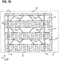
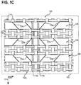
- Fig.1B shows the composite component 100 in a schematic plan view of the strips 124 and the second cover layer 112, clearly without the first cover layer 102 from a view against the direction 101d. Also shows Fig.1C the composite component 100 in a schematic top view of the strips 124 and the first cover layer 102, clearly without the second cover layer 112 from a view along the direction 101d.
- the first fabric 102g and the second fabric 112g can define a warp direction 101k and a weft direction 101s.
- the two fabrics 102g, 112g can, for example, be or become correspondingly aligned relative to one another.
- the two fabrics 102g, 112g can be formed in a common weaving process by means of a weaving device.
- each band of the plurality of bands 124 may extend along the warp direction 101k. This enables, for example, the efficient formation of a textile-technical connection of the bands 124 with the respective fabric 102g, 112g of the two cover layers 102, 112.
- each band of the plurality of bands 124 can be kinked multiple times or have several kink areas in which the respective band is kinked. Accordingly, kink edges 124k are formed in the respective band. The kink edges 124k can run obliquely to the warp direction 101k and / or obliquely to the weft direction 101s. Clearly, the respective kink areas of the strips 124 can be elongated obliquely to the warp direction 101k and / or obliquely to the weft direction 101s.
- a form-fit connection can be formed between each band of the plurality of bands 124 and the threads (for example the warp threads 116 and / or the weft threads 114) of the first fabric 102g and the second fabric 112g.
- the respective band 124 can be coupled into the respective fabric 102g, 112g by means of a plurality of weft threads (see for example the respective weft threads 114s).
- the respective fabric 102g, 112g of the cover layers 102, 112 can be configured as a monofilament, multifilament or staple fiber yarn fabric.
- the respective fabric 102g, 112g of the cover layers 102, 112 can be made by means of a suitable filaments or by means of several suitable filaments or will be produced.
- each kink edge 124k of a tape 124 can run at an angle in a range of approximately 15 ° to 75 ° to the warp direction 101k. Not all of the kink edges 124k have to be oriented in the same direction or run parallel to one another. Rather, the kink edges 124k can either have a first orientation (e.g., parallel to a first direction) or a second orientation (e.g., parallel to a second direction). Both orientations can neither be parallel to the weft direction 101s nor parallel to the warp direction 101k. In other words, the first and second directions cannot run parallel to the warp direction 101k and / or not parallel to the weft direction 101s.
- an adhesive connection can be or will be formed between each of the plurality of tapes 124 and the respective fabric 102g, 112g of the two cover layers 102, 112.
- the adhesive connection can be produced, for example, by means of an activatable adhesive at a predefined point in time by means of a corresponding activation of the activatable adhesive.
- the activatable adhesive can already be applied to the tapes 124 and / or to the respective fabric 102g, 112g at any point in time, for example in sections, before activation.
- the activation of the adhesive can take place (adhesive-specific), for example, by means of light (eg UV light), by means of heat, based on chemical activation, or any other suitable activation.
- each of the plurality of tapes 124 can comprise or consist of a fiber material.
- the bands can clearly be formed from a piece of paper.
- the fiber material can have, for example, vegetable fibers, aramid fibers, carbon fibers, glass fibers, ceramic fibers, and / or other suitable fibers.
- the fibers of the fiber material can be held together by means of a binder.
- the fibers of the fiber material can be, for example, short fibers or super short fibers, for example fibers with an average fiber length in a range from approximately 1 mm to approximately 100 mm, but also continuous fibers.
- the bands 124 can be designed to be rigid in such a way that the composite component 100 is stiffened due to the bands 124 introduced.
- each of the plurality of bands 124 can be set up in such a way that it can be brought into a stable, three-dimensional shape by means of kinking.
- the three-dimensional shape of the bands 124 defined by means of the kink edges 124k can, for example, define the distance 101a between the first cover layer 102 and the second cover layer 112.
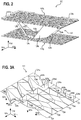
- Fig. 2 illustrates a composite component 100 in a schematic perspective view, according to various embodiments.
- the tapes 124 of the composite component 100 can be connected to the two fabrics 102g, 112g adjoining them in such a way that first tape sections 124a (referred to as first fastening sections) of a tape 124 adjoin the first fabric 102g and / or into the first Fabric 102g are incorporated, that in each case second tape sections 124b (referred to as connecting portions) of a tape 124 are arranged between the two fabrics 102g, 112g and extend from one of the two fabrics 102g, 112g to the other, and that in each case third tape sections 124c (as second Fastening sections designated) of a tape 124 adjoin the second fabric 112g and / or are incorporated into the second fabric 112g.
- first tape sections 124a referred to as first fastening sections
- second tape sections 124b referred to as connecting portions
- first, second and third band sections 124a, 124b, 124c can be present in a predefined order, namely in each case a first band section 124a, followed by a second band section 124b, followed by a third band section 124c, followed by another second band section 124b and starting again with a first band section 124a, etc.
- Fig.3A illustrates an embodiment of a core layer 122 or an embodiment of the strips 124 of a composite component 100 in a schematic perspective view, according to various embodiments.
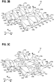
- Fig.3B and Fig.3B show further configurations of a core layer 122 or the strips 124 of a composite component 100 in a schematic perspective view, according to various embodiments.
- the geometric configuration of the bands 124 can be described by means of various surface elements 324a, 324a ', 324b, 324b', 324c, 324c ', as in FIG Fig.3A as well as in Fig.3B and Fig.3C is illustrative.
- a respective band 124 of the core layer 122 of the composite component can have different surface elements 324a, 324a ', 324b, 324b', 324c, 324c 'or be constructed therefrom.
- the second surface elements 324b, 324b' clearly define the connecting sections 124b of the respective tape 124
- the first and / or third surface elements 324a, 324a ', 324c, 324c' can be designed, for example, triangular or square (e.g. trapezoidal) and the second surface elements 324b, 324b 'can be designed, for example, square (e.g. trapezoidal).
- the respective fastening sections 124a, 124c can be designed, for example, triangular or square (e.g. trapezoidal) and the connecting sections 124b can be designed, for example, square (e.g. trapezoidal).
- the first surface elements 324a, 324a ', which define the first fastening section 124 have a greater width than the third surface elements 324c, 324c', which define the second fastening section 124c.
- the first surface elements 324a, 324a ', which define the first fastening section 124 can have a smaller width than the third surface elements 324c, 324c', which define the second fastening section 124c.
- the width of the surface elements or of the corresponding band sections 124a, 124c can be understood as the extension of the band in a direction parallel to the weft direction 101s.
- the surface elements 324a, 324b, 324c can be arranged mirror-symmetrically (for example with respect to a plane parallel to the directions 101d, 101s or perpendicular to the warp direction 101k) to the surface elements 324a ', 324b', 324c '.
- the bands 124 clearly have one thing in common Structural element defined by the corresponding three surface elements 324a, 324b, 324c.
- two strips that are adjacent to one another can be designed mirror-symmetrically to one another (for example with respect to a plane parallel to the directions 101d, 101k or perpendicular to the weft direction 101s).
- the tapes 124 can have predefined kink areas 324k and can accordingly be set up to form a three-dimensional core layer 122, forming the kink edges 124k.
- the thickness of the core layer 122 ie the extent of the core layer parallel to the direction 101d) can be based on the configuration of the surface elements 324a, 324b, 324c.
- each kink edge 124k or each predefined kink region 324k of a first amount can be oriented at a first angle to the warp direction 101k and each kink edge 124k or each predefined kink region 324k of a second amount can be oriented at a second angle to the warp direction 101k wherein the first angle is different from the second angle.
- the kink edges 124k or the predefined kink regions 324k can run parallel to one of two different directions 301a, 301b. Both directions 301a, 301b can be aligned neither parallel to the warp direction 101k nor parallel to the weft direction 101s. Furthermore, the two directions 301a, 301b can be perpendicular to one another.
- the straps 124 of the core layer can be configured such that the first fastening sections 124a and / or the second fastening sections 124c of two mutually adjacent Tapes 124 adjoin one another and form a substantially closed fastening surface to the first fabric 102g or to the second fabric 112g.
- Fig. 4 illustrates a composite component 100 in a schematic perspective view, according to various embodiments.
- the composite component 100 can, for example, have woven cover layers 102, 112 and an arrangement of kinked strips 124 as a core layer between the two cover layers 102, 112.
- the core layer can be coupled to the two cover layers 102, 112 in terms of bonding and thus form-fitting.
- the core layer can clearly be formed by a multiplicity of erected strips 124.
- the bands 124 of the core layer can be or will be processed using weaving technology. Before the weaving-technical processing, the bands 124 can have predefined kink areas 324k with regard to their later arrangement in the core layer (e.g. be pre-folded, perforated, thinned, etc.).
- the tapes 124 can then be fed in the longitudinal direction (warp direction 101k) to the weaving device (not shown) and connected to the cover layers 102, 112 (and / or intermediate surfaces, not shown) in a form-fitting manner by means of weft threads 414s.
- a modification of the weft insertion system of the weaving device is not necessary, for example, and the full weaving performance can thus be achieved.
- At least one core layer is coupled with at least two cover layers in terms of binding technology. It goes without saying that a cover layer can also be arranged between two core layers and thus clearly forms an intermediate layer in the composite. For example, a cover layer does not have to be an outer layer of the composite component.
- the bands 124 While the bands 124 are being fed into the weaving area of a weaving device, they can be in one plane (e.g. parallel to the warp direction 101k and the weft direction 101s or perpendicular to the direction 101d), the strips 124 consequently not yet being kinked, but having, for example, predefined kink areas 324k.
- the then erected, kinked tapes 124 can form the core layer, which is provided between two adjacent layers (referred to as cover layers) and are connected to them by weaving technology.
- the cover layers 102, 112 can be fabric layers or at least each have a fabric.
- the bands 124 can be guided into the weaving area of a weaving device by means of one or more rollers.
- the belts 124 can be passed between two rollers in contact therewith or are transported while lying on several rollers.
- FIG. 10 shows a schematic flow diagram of a method 500 for producing a composite component, for example the composite component 100 described herein, according to various embodiments.
- the method 500 for producing a composite component can for example have the following: in 510, guiding a plurality of strips 124 in a guide plane of a processing device along a guide direction, each of the strips 124 having predefined kink areas 324k which are formed in the respective strip in such a way that these run obliquely to the guide direction; in 520, producing a portion of a first fabric layer 102 by means of the processing device; in 530, connecting the plurality of tapes 124 to the first fabric layer 102, wherein a first fastening portion 124a of the respective tape 124 is connected to the first fabric layer; in 540, folding the plurality of bands 124 in the predefined kink areas 324k, wherein a connecting portion 124b of the respective band 124, which is adjacent to the first fastening portion 124a, is erected; in 550, production of a section of a second fabric layer 112 by means of the processing device; and, in 560, connecting the plurality of tapes
- the raised connecting sections 124b of the plurality of tapes 124 can define a distance 101a between the first fabric layer 102 and the second fabric layer 112, see FIG Fig.1A .
- Example 1 is a composite component 100, comprising: a first cover layer 102 comprising a first fabric 102g; a second cover layer 112 comprising a second fabric 112g, the first fabric 102g and the second fabric 112g defining a warp direction 101k and a weft direction 101s; and a plurality of bands 124 which are arranged between the two cover layers 102, 112.
- Each of the plurality of tapes 124 can be arranged along the warp direction 101k (e.g. clearly extending along the warp direction 101k) and connected to the respective fabric 102g, 112g of the first cover layer 102 and the second cover layer 112.
- Each of the straps 124 can be folded several times, the folded edges 124k extending obliquely to the warp direction 101k and / or obliquely to the weft direction 101s.
- the first cover layer 102 and / or the second cover layer 112 of the composite component 100 can, for example, only have one fabric layer made of the corresponding fabric.
- a composite component 100 can have the following: a first fabric layer 102g; a second layer of fabric 112g, the first fabric layer 102g and the second fabric layer 112g defining a warp direction 101k and a weft direction 101s; and a plurality of straps 124 arranged between the two fabric layers 102g, 112g.
- each of the plurality of bands 124 can extend along the warp direction 101k and be connected (for example by weaving technology) to the respective fabric layer 102g, 112g.
- Each of the straps 124 can be folded several times, the folded edges 124k extending obliquely to the warp direction 101k and / or obliquely to the weft direction 101s.
- first cover layer 102 and / or the second cover layer 112 of the composite component 100 can have, for example, several fabric layers made from the same fabric or from several different fabrics.
- a composite component 100 can have the following: a first cover layer 102 having one or more first fabric layers 102g; a second cover layer 112 having one or more second fabric layers 112g, at least one of the one or more first fabric layers 102g and at least one of the one or more second fabric layers 102g defining a warp direction 101k and a weft direction 101s; and a plurality of bands 124 which are arranged between the two cover layers 102, 112.
- each of the plurality of tapes 124 can extend along the warp direction 101k and be connected to the at least one first fabric layer 102g of the first cover layer 102 and the at least one fabric layer 112g of the second cover layer 112.
- Each of the plurality of tapes 124 can be kinked several times, the kink edges 124k extending obliquely to the warp direction 101k and / or obliquely to the weft direction 101s.
- the first cover layer 102 and / or the second cover layer 112 of the composite component 100 can have, for example, one or more further material layers or the like.
- a protective layer for protecting the fabric layer or the like can be arranged above and / or below a fabric layer.
- the composite component 100 according to example 1 can furthermore have the connection between the respective band 124 and the respective fabric 102g, 112g or the respective fabric layer 102g, 112g by means of a form fit.
- a form-fit connection between elements (e.g. threads, band-shaped elements, etc.) of the respective fabric and each of the bands can be or will be produced.
- each of the bands can be or will be connected to the respective tissue by means of a form-fit connection.
- the form-fit connection (or a textile connection) can preferably be a web connection.
- the composite component 100 according to example 1 or 2 can furthermore have that each of the plurality of strips 124 has a plurality of fastening sections 124a, 124c, each of the fastening sections 124a, 124c being formed between two adjacent kink edges 124k.
- the composite component 100 according to example 3 can furthermore have that each of the plurality of strips 124 has a multiplicity of connection sections 124b, each of the connection sections 124b being formed between two adjacent kink edges 124k.
- the composite component 100 according to example 3 and 4 can furthermore have that the fastening sections 124a, 124c and the connecting sections 124b of a respective band 124 are provided alternately along the warp direction 101k.
- the composite component 100 according to one of examples 3 to 5 can further include that each of the fastening sections 124a, 124c either in the first fabric 102g or the first fabric layer of the first cover layer 102 or in the second fabric 112g or the second fabric layer 112g of the second cover layer 112 is woven in.
- the composite component 100 according to one of examples 3 to 6 can furthermore have that each fastening section 124a of a first set of the fastening sections has a first width and that each fastening section 124c of a second set of the fastening sections has a second width, the first width being different of the second width.
- the composite component 100 according to one of examples 3 to 7 can furthermore have that each of the fastening sections 124a, 124c is essentially planar.
- the composite component 100 according to example 4 can further include that each of the connecting sections 124b extends either from the first cover layer 102 to the second cover layer 112 or from the second cover layer 112 to the first cover layer 102.
- the composite component 100 according to example 4 or 9 can furthermore have that each of the connecting sections 124b is of essentially planar design.
- the composite component 100 according to one of examples 1 to 10 can furthermore have that several of the kink edges 124k run at a first angle to the warp direction 101k and that several of the kink edges 124k run at a second angle to the warp direction 101k, the first Angle is different from the second angle.
- the composite component 100 according to one of examples 1 to 11 can furthermore have that several of the kink edges 124k run parallel to a first direction 301a and that several of the kink edges 124k run parallel to a second direction 301b, the first direction 301a being different from the second direction 301b.
- the first direction 301a and the second direction 301b can run perpendicular to one another.
- the first The direction 301a and the second direction 301b neither run parallel to the warp direction 101k nor parallel to the weft direction 101s.
- the composite component 100 according to one of examples 1 to 12 can furthermore have that each of the kink edges 124k runs at an angle in a range of approximately 15 ° to 75 ° to the warp direction 101k.
- the composite component 100 according to one of examples 1 to 13 can furthermore have that, in addition to the (eg textile-technical) connection, an adhesive connection between each of the plurality of tapes 124 and the respective fabric 102g, 112g of the two cover layers 102, 112 or the one or more fabric layers is formed.
- the composite component 100 according to one of examples 1 to 14 can furthermore have that each of the plurality of strips 124 comprises or consists of a fiber material.
- the composite component 100 according to example 15 can furthermore have that the fiber material comprises plant fibers, aramid fibers, ultra-high molecular weight polyethylene, carbon fibers, glass fibers and / or ceramic fibers.
- the fiber material comprises plant fibers, aramid fibers, ultra-high molecular weight polyethylene, carbon fibers, glass fibers and / or ceramic fibers.
- the composite component 100 according to example 15 or 16 can furthermore have that the fiber material has a binder for holding the fibers of the fiber material together.
- the composite component 100 according to one of examples 15 to 17 can furthermore have that the fiber material has fibers with an average fiber length in a range from approximately 1 mm to approximately 100 mm.
- the composite component 100 according to one of examples 1 to 18 can further include that each of the plurality of bands 124 has a width in a range from approximately 2 mm to approximately 10 cm.
- the composite component 100 according to one of examples 1 to 19 can furthermore have that each of the plurality of strips 124 has a thickness in a range from approximately 50 ⁇ m to approximately 1 cm.
- the bands 124 may also comprise or be made of metal. In another embodiment, the bands 124 can also comprise or consist of a plastic. In yet another embodiment, the bands 124 can also comprise or consist of a composite material, for example CFK (carbon fiber reinforced plastic), GFK (glass fiber reinforced plastic), or another suitable composite material.
- the predefined kink areas 324k can be generated, for example, by means of a perforation. Furthermore, the predefined kink regions 324k can also have a smaller thickness than the rest of the strip (the material thickness can clearly be reduced).
- Example 21 is a method for producing a composite component, the method comprising: guiding a plurality of strips in a guide plane of a processing device along a guide direction, each of the plurality of strips having predefined kink areas which are formed in the respective strip in such a way that they are inclined to run in the guide direction; Producing a section of a first fabric layer by means of the processing device; Connecting the plurality of tapes to the first fabric layer, wherein a first fastening portion of the respective tape is connected to the first fabric layer; Folding the plurality of bands in the predefined kink areas, wherein a connecting section of the respective band, which is adjacent to the first fastening section, is erected; Producing a section of a second fabric layer by means of the processing device; and joining the plurality of ribbons to the second fabric layer, a second Fastening portion of the respective tape, which adjoins the connecting portion, is connected to the second fabric ply, the connecting portion of the respective tape extending from the first fabric ply to the
- the method according to example 21 can further include that the erected connecting sections of the plurality of tapes define a distance between the first fabric layer and the second fabric layer.
- Example 23 is a composite component 100, comprising: a first cover layer 102 comprising a first fabric 102g; a second cover layer 112 comprising a second fabric 112g, the first fabric 102g and the second fabric 112g defining a warp direction 101k and a weft direction 101s; several tapes 124, which are arranged between the two cover layers 102, 112 along the warp direction 101k and positively connected to the respective fabric 102g, 112g of the first cover layer 102 and the second cover layer 112, each of the plurality of tapes 124 being kinked several times and with each other the kink edges 124k extend obliquely to the warp direction 101k and / or obliquely to the weft direction 101s.
- Example 24 is a composite component 100, comprising: a first cover layer 102 comprising a first textile fabric 102g; a second cover layer 112 having a second textile fabric 112g; and a plurality of bands 124 which are arranged between the two cover layers 102, 112.
- each of the plurality of tapes 124 can be arranged along a direction 101k and connected to the respective textile fabric 102g, 112g of the first cover layer 102 and the second cover layer 112 by textile technology.
- Each of the bands 124 can be folded several times, the folded edges 124k extending obliquely to the direction 101k.
- a textile fabric can, for example, have or consist of one of the following: one or more woven fabrics, one or more knitted fabrics, one or more knitted fabrics, one or more braids, one or more stitched fabrics, one or more nonwovens, and / or one or more felts.
- the composite component 100 described herein is configured, for example, in such a way that it is resistant to delamination. Furthermore, according to some embodiments, the composite component 100 described herein can be woven in reproducible quality by means of an automated, one-step process.
- the composite component 100 described herein can furthermore be at least partially filled with at least one filler material.
- a cavity structure formed between the two cover layers 102, 112 and the strips 124 can be or will be partially or completely filled with at least one filler material.
- a foam, a bed, or another suitable material can be used as the filler material.
- the composite component 100 described herein can furthermore have at least one third cover layer with a third fabric and several further tapes 124 which are arranged between the second cover layer 112 and the third cover layer.
- each of the several further bands 124 can be arranged along the warp direction 101k and connected (for example by weaving technology) to the respective adjoining cover layers (for example the second and third cover layers).
- Each of the further strips 124 can be folded several times, with the folded edges 124k extend obliquely to the warp direction 101k and / or obliquely to the weft direction 101s.
- a distance between the first cover layer and the second cover layer can be different from a distance between the second cover layer and the third cover layer.
- different distances between the cover layers can be or are clearly set, for example by adjusting the pre-folding of the tape.
- the composite component 100 described herein can furthermore have at least one third fabric layer and several further tapes 124, which are arranged between the second fabric layer and the third fabric layer.
- each of the plurality of further bands 124 can be arranged along the warp direction 101k and connected (e.g. by weaving technology) to the respective adjacent fabric layers (e.g. the second and third fabric layers).
- Each of the further straps 124 can be folded several times, the folded edges 124k extending obliquely to the warp direction 101k and / or obliquely to the weft direction 101s.
- a distance between the first fabric layer and the second fabric layer can be different from a distance between the second fabric layer and the third fabric layer. For example, different distances between the fabric layers can be or are clearly set, e.g. by adjusting the tape prefold.
- the composite component 100 described herein can furthermore have a curved shape.
- the two cover layers 102, 112 can be correspondingly curved.
- the direction of curvature can be, for example, the warp direction or the weft direction.
- the composite component 100 described herein can furthermore be configured in such a way that the two cover layers 102, 112 (or the fabric layers) are in a first region of the composite component 100 have a first distance from one another and have a second distance from one another in a second region of the composite component 100, wherein the first distance is different from the second distance.
- the two cover layers of the composite component can clearly be aligned obliquely to one another (ie not parallel to one another).
- the variable spacing can be adjusted accordingly, for example, by adapting the pre-folding of the multiple strips.
- the composite component 100 described herein can also be configured such that it has a third cover layer in addition to the first cover layer and the second cover layer, the third cover layer having a third fabric or consists of it.
- a plurality of further strips can be arranged between the second cover layer and the third cover layer along the warp direction and be connected to the respective fabric of the second cover layer and the third cover layer in a form-fitting manner, each of the plurality of further strips being able to be kinked several times and with the kink edges sloping to the warp direction and / or obliquely to the weft direction.
- the plurality of further bands can be arranged along a direction other than the warp direction, for example along the weft direction or along another direction inclined to the warp direction.
- the arrangement (for example the distance between adjacent tapes) of the plurality of (further) tapes arranged between the second and third cover layer can be different from the arrangement of the tapes arranged between the first and second cover layer.
- the configuration (e.g. the material thickness, the width, the distance between adjacent connecting sections, the material, etc.) of the plurality of (further) tapes arranged between the second and third cover layers can be different from the configuration of the ones arranged between the first and second cover layers Be tapes.
- At least two of the composite components 100 described herein can be connected to one another (e.g. one above the other, e.g. directly on top of one another) such that the warp direction 101k of the first composite component 100 extends in a different direction than the warp direction 101k of the second composite component 100.
- the two composite components 100 can clearly be attached to one another rotated against each other (e.g. rotated by 45 ° or 90 ° relative to each other), the first layer of the second composite component being directed towards the first layer of the first composite component .
- the rotation of the two composite components relative to one another takes place clearly around an axis that can be perpendicular to both warp directions. A more stable overall composite component can thus be formed.
Landscapes
- Engineering & Computer Science (AREA)
- Architecture (AREA)
- Civil Engineering (AREA)
- Structural Engineering (AREA)
- Textile Engineering (AREA)
- Mechanical Engineering (AREA)
- Life Sciences & Earth Sciences (AREA)
- Wood Science & Technology (AREA)
- Chemical & Material Sciences (AREA)
- Composite Materials (AREA)
- Woven Fabrics (AREA)
- Laminated Bodies (AREA)
Applications Claiming Priority (1)
| Application Number | Priority Date | Filing Date | Title |
|---|---|---|---|
| DE102019118298.0A DE102019118298A1 (de) | 2019-07-05 | 2019-07-05 | Verbundbauteil und Verfahren zum Herstellen eines Verbundbauteils |
Publications (2)
| Publication Number | Publication Date |
|---|---|
| EP3760428A1 true EP3760428A1 (fr) | 2021-01-06 |
| EP3760428B1 EP3760428B1 (fr) | 2022-10-05 |
Family
ID=71096557
Family Applications (1)
| Application Number | Title | Priority Date | Filing Date |
|---|---|---|---|
| EP20179954.1A Active EP3760428B1 (fr) | 2019-07-05 | 2020-06-15 | Composant composite et procédé de fabrication d'un composant composite |
Country Status (2)
| Country | Link |
|---|---|
| EP (1) | EP3760428B1 (fr) |
| DE (1) | DE102019118298A1 (fr) |
Families Citing this family (1)
| Publication number | Priority date | Publication date | Assignee | Title |
|---|---|---|---|---|
| DE102023107776A1 (de) * | 2023-03-28 | 2024-10-02 | Haver & Boecker Ohg | Kammergewebe und Verfahren zur Verwendung |
Citations (2)
| Publication number | Priority date | Publication date | Assignee | Title |
|---|---|---|---|---|
| DE10228406A1 (de) * | 2001-06-25 | 2003-01-02 | Bernhard Scheuring | Spiralförmiges Strukturelement sowie Verbundbauteil bestehend aus wenigstens einem spiralförmigen Strukturelement und einem Außenbauteil |
| DE102004062895A1 (de) * | 2004-12-20 | 2006-06-29 | Technische Universität Dresden | Textile Abstandsstruktur und Verfahren zu ihrer Herstellung |
-
2019
- 2019-07-05 DE DE102019118298.0A patent/DE102019118298A1/de not_active Withdrawn
-
2020
- 2020-06-15 EP EP20179954.1A patent/EP3760428B1/fr active Active
Patent Citations (2)
| Publication number | Priority date | Publication date | Assignee | Title |
|---|---|---|---|---|
| DE10228406A1 (de) * | 2001-06-25 | 2003-01-02 | Bernhard Scheuring | Spiralförmiges Strukturelement sowie Verbundbauteil bestehend aus wenigstens einem spiralförmigen Strukturelement und einem Außenbauteil |
| DE102004062895A1 (de) * | 2004-12-20 | 2006-06-29 | Technische Universität Dresden | Textile Abstandsstruktur und Verfahren zu ihrer Herstellung |
Also Published As
| Publication number | Publication date |
|---|---|
| EP3760428B1 (fr) | 2022-10-05 |
| DE102019118298A1 (de) | 2021-01-07 |
Similar Documents
| Publication | Publication Date | Title |
|---|---|---|
| EP0261488B1 (fr) | Feutre pour papeterie et son procédé de fabrication | |
| DE4214636A1 (de) | Formbares, multiaxiales Verstärkungsgebilde | |
| DE2927414A1 (de) | Verstaerkungsgewebe fuer harzhaltige laminate | |
| WO2013167362A1 (fr) | Pièce textile, élément en matériau composite comportant une pièce textile et leur procédé de fabrication | |
| DE60121015T2 (de) | Pressfilz für papiermaschine | |
| WO2013127460A1 (fr) | Tissu pour l'utilisation dans des matériaux composites, et procédé de production de tissu et d'un corps en matériau composite | |
| EP0873849A2 (fr) | Structure de renforcement résistant aux charges | |
| EP2128335B1 (fr) | Procédé de fabrication d'une bande de feutre | |
| EP2107159A1 (fr) | Feutre de presse et son procédé de fabrication | |
| EP3765669B1 (fr) | Entoilage pour une machine de fabrication d'une bande de matière fibreuse | |
| EP3760428B1 (fr) | Composant composite et procédé de fabrication d'un composant composite | |
| DE102018110773A1 (de) | Abstandsgewirk mit einer Solltrennstelle | |
| DE60311664T2 (de) | Technisches gewebe mit auf der maschine herstellbaren nähten und nahtverstärkungsringen | |
| WO2023110220A1 (fr) | Structure de base, vêtement et procédé de production | |
| EP2236666B1 (fr) | Feutre de presse ayant une zone de jonction et étant doté d'une structure de support non tissée fabriquée à plat | |
| WO2015007844A1 (fr) | Entoilage et procédé de fabrication d'un entoilage | |
| EP2465982B1 (fr) | Tissu pour l'utilisation dans des matières composites et procédé de fabrication du tissu et d'un corps en matière composite | |
| DE19930917C1 (de) | Verfahren zur Herstellung von elastischen Bändern für die Bekleidungsindustrie | |
| EP3475481B1 (fr) | Toile pour une machine de fabrication d'une bande de matériau fibreux et procédé de fabrication d'une telle toile | |
| EP3036372B1 (fr) | Habillage et procédé pour sa fabrication | |
| DE102008000123A1 (de) | Papiermaschinenbespannung mit Scharniernaht | |
| EP3011103B1 (fr) | Entoilage et son procédé de fabrication | |
| DE102022108072A1 (de) | Bespannung für eine Maschine zum Produzieren einer Faserbahn und Verfahren zum Produzieren einer Faserbahn | |
| WO2021223949A1 (fr) | Composant composite, composant et procédé de production d'un composant composite | |
| DE102011007284A1 (de) | Verfahren zur Herstellung eines Endlosmoduls für eine Papiermaschinenbespannung |
Legal Events
| Date | Code | Title | Description |
|---|---|---|---|
| PUAI | Public reference made under article 153(3) epc to a published international application that has entered the european phase |
Free format text: ORIGINAL CODE: 0009012 |
|
| STAA | Information on the status of an ep patent application or granted ep patent |
Free format text: STATUS: THE APPLICATION HAS BEEN PUBLISHED |
|
| AK | Designated contracting states |
Kind code of ref document: A1 Designated state(s): AL AT BE BG CH CY CZ DE DK EE ES FI FR GB GR HR HU IE IS IT LI LT LU LV MC MK MT NL NO PL PT RO RS SE SI SK SM TR |
|
| AX | Request for extension of the european patent |
Extension state: BA ME |
|
| STAA | Information on the status of an ep patent application or granted ep patent |
Free format text: STATUS: REQUEST FOR EXAMINATION WAS MADE |
|
| 17P | Request for examination filed |
Effective date: 20210517 |
|
| RBV | Designated contracting states (corrected) |
Designated state(s): AL AT BE BG CH CY CZ DE DK EE ES FI FR GB GR HR HU IE IS IT LI LT LU LV MC MK MT NL NO PL PT RO RS SE SI SK SM TR |
|
| GRAP | Despatch of communication of intention to grant a patent |
Free format text: ORIGINAL CODE: EPIDOSNIGR1 |
|
| STAA | Information on the status of an ep patent application or granted ep patent |
Free format text: STATUS: GRANT OF PATENT IS INTENDED |
|
| INTG | Intention to grant announced |
Effective date: 20220426 |
|
| GRAS | Grant fee paid |
Free format text: ORIGINAL CODE: EPIDOSNIGR3 |
|
| GRAA | (expected) grant |
Free format text: ORIGINAL CODE: 0009210 |
|
| STAA | Information on the status of an ep patent application or granted ep patent |
Free format text: STATUS: THE PATENT HAS BEEN GRANTED |
|
| AK | Designated contracting states |
Kind code of ref document: B1 Designated state(s): AL AT BE BG CH CY CZ DE DK EE ES FI FR GB GR HR HU IE IS IT LI LT LU LV MC MK MT NL NO PL PT RO RS SE SI SK SM TR |
|
| REG | Reference to a national code |
Ref country code: GB Ref legal event code: FG4D Free format text: NOT ENGLISH |
|
| REG | Reference to a national code |
Ref country code: CH Ref legal event code: EP |
|
| REG | Reference to a national code |
Ref country code: AT Ref legal event code: REF Ref document number: 1522509 Country of ref document: AT Kind code of ref document: T Effective date: 20221015 |
|
| REG | Reference to a national code |
Ref country code: IE Ref legal event code: FG4D Free format text: LANGUAGE OF EP DOCUMENT: GERMAN |
|
| REG | Reference to a national code |
Ref country code: DE Ref legal event code: R096 Ref document number: 502020001791 Country of ref document: DE |
|
| REG | Reference to a national code |
Ref country code: SE Ref legal event code: TRGR |
|
| REG | Reference to a national code |
Ref country code: LT Ref legal event code: MG9D |
|
| REG | Reference to a national code |
Ref country code: NL Ref legal event code: MP Effective date: 20221005 |
|
| PG25 | Lapsed in a contracting state [announced via postgrant information from national office to epo] |
Ref country code: NL Free format text: LAPSE BECAUSE OF FAILURE TO SUBMIT A TRANSLATION OF THE DESCRIPTION OR TO PAY THE FEE WITHIN THE PRESCRIBED TIME-LIMIT Effective date: 20221005 |
|
| PG25 | Lapsed in a contracting state [announced via postgrant information from national office to epo] |
Ref country code: PT Free format text: LAPSE BECAUSE OF FAILURE TO SUBMIT A TRANSLATION OF THE DESCRIPTION OR TO PAY THE FEE WITHIN THE PRESCRIBED TIME-LIMIT Effective date: 20230206 Ref country code: NO Free format text: LAPSE BECAUSE OF FAILURE TO SUBMIT A TRANSLATION OF THE DESCRIPTION OR TO PAY THE FEE WITHIN THE PRESCRIBED TIME-LIMIT Effective date: 20230105 Ref country code: LT Free format text: LAPSE BECAUSE OF FAILURE TO SUBMIT A TRANSLATION OF THE DESCRIPTION OR TO PAY THE FEE WITHIN THE PRESCRIBED TIME-LIMIT Effective date: 20221005 Ref country code: FI Free format text: LAPSE BECAUSE OF FAILURE TO SUBMIT A TRANSLATION OF THE DESCRIPTION OR TO PAY THE FEE WITHIN THE PRESCRIBED TIME-LIMIT Effective date: 20221005 Ref country code: ES Free format text: LAPSE BECAUSE OF FAILURE TO SUBMIT A TRANSLATION OF THE DESCRIPTION OR TO PAY THE FEE WITHIN THE PRESCRIBED TIME-LIMIT Effective date: 20221005 |
|
| PG25 | Lapsed in a contracting state [announced via postgrant information from national office to epo] |
Ref country code: RS Free format text: LAPSE BECAUSE OF FAILURE TO SUBMIT A TRANSLATION OF THE DESCRIPTION OR TO PAY THE FEE WITHIN THE PRESCRIBED TIME-LIMIT Effective date: 20221005 Ref country code: PL Free format text: LAPSE BECAUSE OF FAILURE TO SUBMIT A TRANSLATION OF THE DESCRIPTION OR TO PAY THE FEE WITHIN THE PRESCRIBED TIME-LIMIT Effective date: 20221005 Ref country code: LV Free format text: LAPSE BECAUSE OF FAILURE TO SUBMIT A TRANSLATION OF THE DESCRIPTION OR TO PAY THE FEE WITHIN THE PRESCRIBED TIME-LIMIT Effective date: 20221005 Ref country code: IS Free format text: LAPSE BECAUSE OF FAILURE TO SUBMIT A TRANSLATION OF THE DESCRIPTION OR TO PAY THE FEE WITHIN THE PRESCRIBED TIME-LIMIT Effective date: 20230205 Ref country code: HR Free format text: LAPSE BECAUSE OF FAILURE TO SUBMIT A TRANSLATION OF THE DESCRIPTION OR TO PAY THE FEE WITHIN THE PRESCRIBED TIME-LIMIT Effective date: 20221005 Ref country code: GR Free format text: LAPSE BECAUSE OF FAILURE TO SUBMIT A TRANSLATION OF THE DESCRIPTION OR TO PAY THE FEE WITHIN THE PRESCRIBED TIME-LIMIT Effective date: 20230106 |
|
| P01 | Opt-out of the competence of the unified patent court (upc) registered |
Effective date: 20230524 |
|
| REG | Reference to a national code |
Ref country code: DE Ref legal event code: R097 Ref document number: 502020001791 Country of ref document: DE |
|
| PG25 | Lapsed in a contracting state [announced via postgrant information from national office to epo] |
Ref country code: SM Free format text: LAPSE BECAUSE OF FAILURE TO SUBMIT A TRANSLATION OF THE DESCRIPTION OR TO PAY THE FEE WITHIN THE PRESCRIBED TIME-LIMIT Effective date: 20221005 Ref country code: RO Free format text: LAPSE BECAUSE OF FAILURE TO SUBMIT A TRANSLATION OF THE DESCRIPTION OR TO PAY THE FEE WITHIN THE PRESCRIBED TIME-LIMIT Effective date: 20221005 Ref country code: EE Free format text: LAPSE BECAUSE OF FAILURE TO SUBMIT A TRANSLATION OF THE DESCRIPTION OR TO PAY THE FEE WITHIN THE PRESCRIBED TIME-LIMIT Effective date: 20221005 Ref country code: DK Free format text: LAPSE BECAUSE OF FAILURE TO SUBMIT A TRANSLATION OF THE DESCRIPTION OR TO PAY THE FEE WITHIN THE PRESCRIBED TIME-LIMIT Effective date: 20221005 Ref country code: CZ Free format text: LAPSE BECAUSE OF FAILURE TO SUBMIT A TRANSLATION OF THE DESCRIPTION OR TO PAY THE FEE WITHIN THE PRESCRIBED TIME-LIMIT Effective date: 20221005 |
|
| PLBE | No opposition filed within time limit |
Free format text: ORIGINAL CODE: 0009261 |
|
| STAA | Information on the status of an ep patent application or granted ep patent |
Free format text: STATUS: NO OPPOSITION FILED WITHIN TIME LIMIT |
|
| PG25 | Lapsed in a contracting state [announced via postgrant information from national office to epo] |
Ref country code: SK Free format text: LAPSE BECAUSE OF FAILURE TO SUBMIT A TRANSLATION OF THE DESCRIPTION OR TO PAY THE FEE WITHIN THE PRESCRIBED TIME-LIMIT Effective date: 20221005 Ref country code: AL Free format text: LAPSE BECAUSE OF FAILURE TO SUBMIT A TRANSLATION OF THE DESCRIPTION OR TO PAY THE FEE WITHIN THE PRESCRIBED TIME-LIMIT Effective date: 20221005 |
|
| 26N | No opposition filed |
Effective date: 20230706 |
|
| PG25 | Lapsed in a contracting state [announced via postgrant information from national office to epo] |
Ref country code: SI Free format text: LAPSE BECAUSE OF FAILURE TO SUBMIT A TRANSLATION OF THE DESCRIPTION OR TO PAY THE FEE WITHIN THE PRESCRIBED TIME-LIMIT Effective date: 20221005 |
|
| PG25 | Lapsed in a contracting state [announced via postgrant information from national office to epo] |
Ref country code: MC Free format text: LAPSE BECAUSE OF FAILURE TO SUBMIT A TRANSLATION OF THE DESCRIPTION OR TO PAY THE FEE WITHIN THE PRESCRIBED TIME-LIMIT Effective date: 20221005 |
|
| PG25 | Lapsed in a contracting state [announced via postgrant information from national office to epo] |
Ref country code: MC Free format text: LAPSE BECAUSE OF FAILURE TO SUBMIT A TRANSLATION OF THE DESCRIPTION OR TO PAY THE FEE WITHIN THE PRESCRIBED TIME-LIMIT Effective date: 20221005 |
|
| REG | Reference to a national code |
Ref country code: CH Ref legal event code: PL |
|
| REG | Reference to a national code |
Ref country code: BE Ref legal event code: MM Effective date: 20230630 |
|
| PG25 | Lapsed in a contracting state [announced via postgrant information from national office to epo] |
Ref country code: LU Free format text: LAPSE BECAUSE OF NON-PAYMENT OF DUE FEES Effective date: 20230615 |
|
| REG | Reference to a national code |
Ref country code: IE Ref legal event code: MM4A |
|
| PG25 | Lapsed in a contracting state [announced via postgrant information from national office to epo] |
Ref country code: LU Free format text: LAPSE BECAUSE OF NON-PAYMENT OF DUE FEES Effective date: 20230615 |
|
| PG25 | Lapsed in a contracting state [announced via postgrant information from national office to epo] |
Ref country code: IE Free format text: LAPSE BECAUSE OF NON-PAYMENT OF DUE FEES Effective date: 20230615 |
|
| PG25 | Lapsed in a contracting state [announced via postgrant information from national office to epo] |
Ref country code: IE Free format text: LAPSE BECAUSE OF NON-PAYMENT OF DUE FEES Effective date: 20230615 Ref country code: CH Free format text: LAPSE BECAUSE OF NON-PAYMENT OF DUE FEES Effective date: 20230630 |
|
| PG25 | Lapsed in a contracting state [announced via postgrant information from national office to epo] |
Ref country code: IT Free format text: LAPSE BECAUSE OF FAILURE TO SUBMIT A TRANSLATION OF THE DESCRIPTION OR TO PAY THE FEE WITHIN THE PRESCRIBED TIME-LIMIT Effective date: 20221005 Ref country code: BE Free format text: LAPSE BECAUSE OF NON-PAYMENT OF DUE FEES Effective date: 20230630 |
|
| PG25 | Lapsed in a contracting state [announced via postgrant information from national office to epo] |
Ref country code: BG Free format text: LAPSE BECAUSE OF FAILURE TO SUBMIT A TRANSLATION OF THE DESCRIPTION OR TO PAY THE FEE WITHIN THE PRESCRIBED TIME-LIMIT Effective date: 20221005 |
|
| PG25 | Lapsed in a contracting state [announced via postgrant information from national office to epo] |
Ref country code: BG Free format text: LAPSE BECAUSE OF FAILURE TO SUBMIT A TRANSLATION OF THE DESCRIPTION OR TO PAY THE FEE WITHIN THE PRESCRIBED TIME-LIMIT Effective date: 20221005 |
|
| PGFP | Annual fee paid to national office [announced via postgrant information from national office to epo] |
Ref country code: DE Payment date: 20250618 Year of fee payment: 6 |
|
| PGFP | Annual fee paid to national office [announced via postgrant information from national office to epo] |
Ref country code: GB Payment date: 20250620 Year of fee payment: 6 |
|
| PGFP | Annual fee paid to national office [announced via postgrant information from national office to epo] |
Ref country code: FR Payment date: 20250626 Year of fee payment: 6 |
|
| PGFP | Annual fee paid to national office [announced via postgrant information from national office to epo] |
Ref country code: AT Payment date: 20250721 Year of fee payment: 5 |
|
| PG25 | Lapsed in a contracting state [announced via postgrant information from national office to epo] |
Ref country code: CY Free format text: LAPSE BECAUSE OF FAILURE TO SUBMIT A TRANSLATION OF THE DESCRIPTION OR TO PAY THE FEE WITHIN THE PRESCRIBED TIME-LIMIT; INVALID AB INITIO Effective date: 20200615 |
|
| PGFP | Annual fee paid to national office [announced via postgrant information from national office to epo] |
Ref country code: SE Payment date: 20250618 Year of fee payment: 6 |
|
| PG25 | Lapsed in a contracting state [announced via postgrant information from national office to epo] |
Ref country code: HU Free format text: LAPSE BECAUSE OF FAILURE TO SUBMIT A TRANSLATION OF THE DESCRIPTION OR TO PAY THE FEE WITHIN THE PRESCRIBED TIME-LIMIT; INVALID AB INITIO Effective date: 20200615 |
|
| PG25 | Lapsed in a contracting state [announced via postgrant information from national office to epo] |
Ref country code: TR Free format text: LAPSE BECAUSE OF FAILURE TO SUBMIT A TRANSLATION OF THE DESCRIPTION OR TO PAY THE FEE WITHIN THE PRESCRIBED TIME-LIMIT Effective date: 20221005 |