EP3760457A1 - Unité de décollage de talon pour machines à changer les pneus - Google Patents
Unité de décollage de talon pour machines à changer les pneus Download PDFInfo
- Publication number
- EP3760457A1 EP3760457A1 EP20183103.9A EP20183103A EP3760457A1 EP 3760457 A1 EP3760457 A1 EP 3760457A1 EP 20183103 A EP20183103 A EP 20183103A EP 3760457 A1 EP3760457 A1 EP 3760457A1
- Authority
- EP
- European Patent Office
- Prior art keywords
- bead breaking
- tyre
- bead
- arm
- tool
- Prior art date
- Legal status (The legal status is an assumption and is not a legal conclusion. Google has not performed a legal analysis and makes no representation as to the accuracy of the status listed.)
- Withdrawn
Links
- 239000011324 bead Substances 0.000 title claims abstract description 92
- 230000003534 oscillatory effect Effects 0.000 claims description 2
- 230000008878 coupling Effects 0.000 description 2
- 238000010168 coupling process Methods 0.000 description 2
- 238000005859 coupling reaction Methods 0.000 description 2
- 239000012530 fluid Substances 0.000 description 2
- 230000004913 activation Effects 0.000 description 1
- 230000005923 long-lasting effect Effects 0.000 description 1
- 238000003754 machining Methods 0.000 description 1
- 230000000284 resting effect Effects 0.000 description 1
Images


Classifications
-
- B—PERFORMING OPERATIONS; TRANSPORTING
- B60—VEHICLES IN GENERAL
- B60C—VEHICLE TYRES; TYRE INFLATION; TYRE CHANGING; CONNECTING VALVES TO INFLATABLE ELASTIC BODIES IN GENERAL; DEVICES OR ARRANGEMENTS RELATED TO TYRES
- B60C25/00—Apparatus or tools adapted for mounting, removing or inspecting tyres
- B60C25/01—Apparatus or tools adapted for mounting, removing or inspecting tyres for removing tyres from or mounting tyres on wheels
- B60C25/05—Machines
- B60C25/125—Machines for only breaking the beads
- B60C25/13—Machines for only breaking the beads acting axially on a part of the bead or side wall only at localised regions of the bead or side wall
-
- B—PERFORMING OPERATIONS; TRANSPORTING
- B60—VEHICLES IN GENERAL
- B60C—VEHICLE TYRES; TYRE INFLATION; TYRE CHANGING; CONNECTING VALVES TO INFLATABLE ELASTIC BODIES IN GENERAL; DEVICES OR ARRANGEMENTS RELATED TO TYRES
- B60C25/00—Apparatus or tools adapted for mounting, removing or inspecting tyres
- B60C25/01—Apparatus or tools adapted for mounting, removing or inspecting tyres for removing tyres from or mounting tyres on wheels
- B60C25/05—Machines
- B60C25/132—Machines for removing and mounting tyres
- B60C25/135—Machines for removing and mounting tyres having a tyre support or a tool, movable along wheel axis
- B60C25/138—Machines for removing and mounting tyres having a tyre support or a tool, movable along wheel axis with rotary motion of tool or tyre support
Definitions
- the present invention relates to a bead breaking unit for tyre changing machines.
- the tyre changing machines are commonly used for the fitting/removal of wheel tyres for vehicles onto/from the respective rims.
- the known tyre changing machines comprise a bead breaking unit comprising a bead breaking arm arranged horizontally and having a first end hinged to a sidewall of the casing, or bedplate, of the machine itself and a second end provided with a bead breaking tool, also called "blade".
- the arm is operated by a pneumatic or hydraulic cylinder also associated with the sidewall of the bedplate onto which the bead breaking arm is hinged.
- the bedplate is also provided with an abutment surface that operates in conjunction with the blade to carry out bead breaking.
- the bead breaking arm is moved in a flag fashion between an opening position, to allow the fitting of the wheel to be removed between the abutment surface and the arm, and a closing position, wherein the blade presses on the beads of each tyre sidewall, detaching them from the edges of the wheel rim.
- the bead breaking operation takes place on both sidewalls of the wheel and with several operations.
- the blade is pressed onto the tyre by means of the flag movement of the bead breaking arm, thus causing the bead to partially detach from the wheel rim by, e.g., 1 mm. Subsequently, the wheel is rotated by an operator so that the operation can be repeated on another portion of the tyre.
- the bead breaking operation carried out by an operator, is thus long lasting and requires several wheel turns.
- the main aim of the present invention is to devise a bead breaking unit for tyre changing machines that allows reducing the working time required to carry out complete bead breaking.
- the present invention aims to devise a solution that makes it possible to complete bead breaking, e.g., in a single turn of the tyre for both sidewalls of the wheel, thus reducing the work done by the operator.
- the present invention therefore relates to a bead breaking unit for tyre changing machines in accordance with claim 1 and provided with a bead breaking arm and with a vibrating bead breaking tool which make it possible to overcome the drawbacks mentioned above with reference to the prior art.
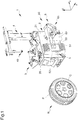
- reference numeral 6 globally indicates a bead breaking unit for tyre changing machines 1.
- the bead breaking unit 6 is mounted on a tyre changing machine 1 and can be used for the first detachment of the bead of a tyre P from the rim C thereof, prior to the removal operation of the tyre P itself carried out on the tyre changing machine 1.
- the tyre changing machine 1 comprises a bedplate 2 on which are arranged a gripping and rotation assembly 3 of a wheel R and an arm 4 provided with a tool 40 to remove the tyre P as a result of its preliminary bead breaking.
- the tyre changing machine 1 is also provided with a counteracting element 5 adapted to operate in conjunction with the bead breaking unit 6 to remove the tyre P.
- the bedplate 2 comprises a frame structure resting or fixed to the ground having a substantially parallelepiped shape in which four sidewalls are located vertically and perpendicular to each other and an upper closure base 20 arranged horizontally along a plane X-Y.
- the gripping and rotation assembly 3 of the wheel and the arm 4 while on a sidewall 21 of the bedplate 2, corresponding to one of the largest sides of the frame, are fixed the bead breaking unit 6 and the counteracting element 5.
- the counteracting element 5 comprises an abutment surface 50 against which, in use, each sidewall of the wheel R is placed in order to remove the tyre P.
- the abutment surface 50 of the counteracting element 5 extends vertically and parallel to the sidewall 21 of the bedplate 2.
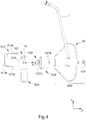
- the bead breaking unit 6 comprises a frame 60 and a bead breaking arm 61 mounted thereon.
- the frame 60 comprises a supporting bar 600 elongated and extended, in use, horizontally between a first end 600a and a second end 600b.
- the bead breaking arm 61 is mounted at the second end 600b of the supporting bar 600.
- the bead breaking arm 61 also comprises an elongated element 610 that extends between two extremities 610a, 610b.
- the first extremity 610a of the elongated element 610 is hinged to the second end 600b of the supporting bar 600 so that the elongated element 610 can rotate around a vertical axis z1.
- the elongated element 610 comprises two profiled elements 611, 612 inclined to each other to form an elbow-shaped portion in a substantially central position between the profiled elements 611, 612.
- Alternative embodiments cannot however be ruled out wherein the bead breaking arm 61 has a different shape and consists, e.g., of a single straight profiled element or of one or more curved profiled elements.
- the elongated element 610 and therefore the profiled elements 611, 612, have a substantially "C" shape in which are identified, for each one, an external lateral surface 611a,612a, an upper surface 611b,612b and a lower surface 611c,612c substantially rectangular.
- the internal side of the profiled elements 611,612, and therefore of the "C" profiled element faces the sidewall 21 of the bedplate 2.
- the bead breaking unit 6 comprises a bead breaking tool 62, also called “blade”, adapted to remove the tyre P from the wheel R and, advantageously, actuation means 63 associated with the blade 62 to make it vibrate, the operation of which will be described in detail later in the present description.
- a bead breaking tool 62 also called “blade”
- actuation means 63 associated with the blade 62 to make it vibrate
- the bead breaking unit 6 also comprises a driving actuator 8 for the movement of the arm 61 between a disengagement position, wherein the blade 62 is further away from the abutment surface 50, and an intervention position, wherein the blade 62 is close to the abutment surface 50 and is adapted to engage at one side of the tyre P.
- the driving actuator 8 is placed between the frame 60 and the bead breaking arm 61.
- the driving actuator 8 is of the fluid type, i.e. it consists of a pneumatic or hydraulic actuator, such as a cylinder/piston pair, and is connected to a fluid activation circuit (not shown).
- the driving actuator 8 is connected to the arm 61 at the opposite side of the elbow-shaped portion between the two profiled sections 611,612. More specifically, between the driving actuator 8 and the arm 61 there is a connecting element 614 attached at one end to the elbow-shaped portion between the two profiled elements and at the other end to the driving actuator 8 and intended to transfer the motion of the driving actuator 8 to the bead breaking arm 61.
- the blade 62 is conveniently associated with a control lever 7, preferably fixed at the extremity 610 of the arm 61 to be gripped by an operator and adapted to make the tyre removal operation easier and more practical.
- the bead breaking tool 62 has a "blade" shape.
- the bead breaking tool 62 has a concavity such as to adapt to the curvature of the tyre P.
- the latter comprise a motorized cylinder 630, a rotating shaft 631 and a cam 633 fitted onto the shaft 631.
- the motorized cylinder 630 supports the shaft 631 to make it rotate around its own substantially vertical axis z2 so that the rotary motion of the shaft 631 causes an oscillatory motion for the cam 633 along a direction y1 substantially orthogonal to the direction z2.
- the actuation means 63 comprise a piston 637 which can be engaged with the cam 633, at one of its terminal ends 637a, and with the blade 62 at a second of its terminal ends 637b, opposite the first end 367a.
- the piston 637 is moved along the direction y1 to advantageously make the blade 62 vibrate during the tyre removal operation.
- the piston 637 is supported in a sliding manner by the bead breaking arm 61 at the extremity 610b thereof.
- the piston 637 is held by a perforated support 635 and fixed at the extremity 610b of the arm 61 and is intended to receive a cylindrical element 636 which allows the piston 637 to slide therein.
- the support 635 is fixed and locked together with the extremity 610b of the bead breaking arm 61.
- the second terminal end 637b of the piston 637 is intended to be fixed to the blade 62 by means of a coupling element 632.
- the second terminal end 637b of the piston 637 is inserted into a hole obtained in the coupling element 632 and is locked by a bolt 634.
- the extremity 610b of the bead breaking arm 61 also comprises a housing 613, overhanging from the external lateral surface 612a of the profiled element 612, to support the shaft 632 and thus the entire actuator 63.
- the housing 613 has a "C" shape in which there are an external lateral surface 613a, an upper surface 613b and a lower surface 613c which are substantially perpendicular to each other. More particularly, the internal side of the housing 613, and therefore of the "C" profile, faces the external lateral surface 612a of the profiled element 612.
- Two coaxial holes arranged diametrically opposite on the upper surface 613b and the lower surface 613c, are made on the housing 613 to receive the shaft 632 and allow the latter to rotate around the axis z2.
- the holes allow making a revolute pair between the housing 613 and the shaft 631 and therefore the actuator 63.
- the shaft 631 is fitted into the housing 613 through the two holes, while the cylinder 630 is arranged outside the housing 613 and fixed to the lower surface 613c of the housing 613.
- the described invention achieves the intended objects and in particular it is underlined that, by means of the bead breaking unit for tyre changing machines, it is possible to carry out bead breaking in just one turn of the tyre thanks to the presence of a vibrating bead breaking tool which helps the operator to speed up and therefore reduce the working time during bead breaking.
Landscapes
- Engineering & Computer Science (AREA)
- Mechanical Engineering (AREA)
- Vehicle Cleaning, Maintenance, Repair, Refitting, And Outriggers (AREA)
- Moulds For Moulding Plastics Or The Like (AREA)
- Tyre Moulding (AREA)
Applications Claiming Priority (1)
| Application Number | Priority Date | Filing Date | Title |
|---|---|---|---|
| IT102019000010590A IT201900010590A1 (it) | 2019-07-01 | 2019-07-01 | Gruppo stallonatore per macchine smontagomme |
Publications (1)
| Publication Number | Publication Date |
|---|---|
| EP3760457A1 true EP3760457A1 (fr) | 2021-01-06 |
Family
ID=68343324
Family Applications (1)
| Application Number | Title | Priority Date | Filing Date |
|---|---|---|---|
| EP20183103.9A Withdrawn EP3760457A1 (fr) | 2019-07-01 | 2020-06-30 | Unité de décollage de talon pour machines à changer les pneus |
Country Status (2)
| Country | Link |
|---|---|
| EP (1) | EP3760457A1 (fr) |
| IT (1) | IT201900010590A1 (fr) |
Citations (3)
| Publication number | Priority date | Publication date | Assignee | Title |
|---|---|---|---|---|
| US20140311681A1 (en) * | 2013-04-23 | 2014-10-23 | Bridgestone Americas Tire Operations, Llc | Ultrasonic tire mounting machine |
| EP2796302A1 (fr) * | 2013-04-23 | 2014-10-29 | Giuliano Group S.p.A. | Unité de démonte-talons pour machines de changement de pneus |
| EP2930038A1 (fr) * | 2014-03-14 | 2015-10-14 | SICAM S.r.l. | Unité de briseur de talons |
-
2019
- 2019-07-01 IT IT102019000010590A patent/IT201900010590A1/it unknown
-
2020
- 2020-06-30 EP EP20183103.9A patent/EP3760457A1/fr not_active Withdrawn
Patent Citations (3)
| Publication number | Priority date | Publication date | Assignee | Title |
|---|---|---|---|---|
| US20140311681A1 (en) * | 2013-04-23 | 2014-10-23 | Bridgestone Americas Tire Operations, Llc | Ultrasonic tire mounting machine |
| EP2796302A1 (fr) * | 2013-04-23 | 2014-10-29 | Giuliano Group S.p.A. | Unité de démonte-talons pour machines de changement de pneus |
| EP2930038A1 (fr) * | 2014-03-14 | 2015-10-14 | SICAM S.r.l. | Unité de briseur de talons |
Also Published As
| Publication number | Publication date |
|---|---|
| IT201900010590A1 (it) | 2021-01-01 |
Similar Documents
| Publication | Publication Date | Title |
|---|---|---|
| JP5651351B2 (ja) | 乗物の車輪のタイア着脱用機械 | |
| US9216621B2 (en) | Apparatus for angular positioning of an operating arm of a tire changing machine | |
| JP5014928B2 (ja) | 乗物用ホイールの取り付けおよび取り外し用機械 | |
| US8684060B2 (en) | Tyre-changing machine and a relative bead-breaking method | |
| CN107856482B (zh) | 一种拆胎机 | |
| CN101754876B (zh) | 用于换胎机的卡盘 | |
| CN108016221B (zh) | 用于安装和移除轮胎的设备 | |
| EP2524819B1 (fr) | Unité de démonte-talons pour machines de changement de pneus | |
| EP2338705B1 (fr) | Unité de démonte-talons pour machines de changement de pneus | |
| JP4826984B2 (ja) | ブレーキシューのリベット加工装置 | |
| JP2002029231A (ja) | タイヤ取り外し機用の自動ビード解放装置及びそれを具備したタイヤ取り外し機 | |
| US20110155329A1 (en) | Device for fitting and removing tyres | |
| CN107953732B (zh) | 轮胎更换机 | |
| EP2527166B1 (fr) | Unité de démonte-talons pour machines de changement de pneus | |
| EP2796302A1 (fr) | Unité de démonte-talons pour machines de changement de pneus | |
| ES2924840T3 (es) | Aparato para cambiar neumáticos | |
| CN105984294B (zh) | 一种用于轮胎拆装机的操作头 | |
| EP2705964A1 (fr) | Appareil de verrouillage de jantes de roue pour véhicules sur des machines d'atelier de réparation ou similaires | |
| JP4764645B2 (ja) | 乗物用車輪のタイヤの着脱用機械 | |
| EP2133220A1 (fr) | Dispositif pour élever et postionner des roues d'un véhicule | |
| US4324282A (en) | Tire changing apparatus | |
| CN115279601A (zh) | 轮胎更换机 | |
| IT201900010590A1 (it) | Gruppo stallonatore per macchine smontagomme | |
| JP5026476B2 (ja) | タイヤ着脱機に装着されるビード落し装置 | |
| EP1717064B1 (fr) | Outil pour le montage/ démontage des pneumatiques |
Legal Events
| Date | Code | Title | Description |
|---|---|---|---|
| PUAI | Public reference made under article 153(3) epc to a published international application that has entered the european phase |
Free format text: ORIGINAL CODE: 0009012 |
|
| STAA | Information on the status of an ep patent application or granted ep patent |
Free format text: STATUS: THE APPLICATION HAS BEEN PUBLISHED |
|
| AK | Designated contracting states |
Kind code of ref document: A1 Designated state(s): AL AT BE BG CH CY CZ DE DK EE ES FI FR GB GR HR HU IE IS IT LI LT LU LV MC MK MT NL NO PL PT RO RS SE SI SK SM TR |
|
| AX | Request for extension of the european patent |
Extension state: BA ME |
|
| STAA | Information on the status of an ep patent application or granted ep patent |
Free format text: STATUS: REQUEST FOR EXAMINATION WAS MADE |
|
| RAP1 | Party data changed (applicant data changed or rights of an application transferred) |
Owner name: SICAM S.R.L. |
|
| 17P | Request for examination filed |
Effective date: 20210629 |
|
| RBV | Designated contracting states (corrected) |
Designated state(s): AL AT BE BG CH CY CZ DE DK EE ES FI FR GB GR HR HU IE IS IT LI LT LU LV MC MK MT NL NO PL PT RO RS SE SI SK SM TR |
|
| RIC1 | Information provided on ipc code assigned before grant |
Ipc: B60C 25/138 20060101ALI20211011BHEP Ipc: B60C 25/13 20060101AFI20211011BHEP |
|
| GRAP | Despatch of communication of intention to grant a patent |
Free format text: ORIGINAL CODE: EPIDOSNIGR1 |
|
| STAA | Information on the status of an ep patent application or granted ep patent |
Free format text: STATUS: GRANT OF PATENT IS INTENDED |
|
| INTG | Intention to grant announced |
Effective date: 20220110 |
|
| STAA | Information on the status of an ep patent application or granted ep patent |
Free format text: STATUS: THE APPLICATION IS DEEMED TO BE WITHDRAWN |
|
| 18D | Application deemed to be withdrawn |
Effective date: 20220521 |