EP3760497A1 - Bras d'essuie-glace - Google Patents
Bras d'essuie-glace Download PDFInfo
- Publication number
- EP3760497A1 EP3760497A1 EP19760940.7A EP19760940A EP3760497A1 EP 3760497 A1 EP3760497 A1 EP 3760497A1 EP 19760940 A EP19760940 A EP 19760940A EP 3760497 A1 EP3760497 A1 EP 3760497A1
- Authority
- EP
- European Patent Office
- Prior art keywords
- hose
- joint member
- arm
- arm head
- wiping
- Prior art date
- Legal status (The legal status is an assumption and is not a legal conclusion. Google has not performed a legal analysis and makes no representation as to the accuracy of the status listed.)
- Granted
Links
Images







Classifications
-
- B—PERFORMING OPERATIONS; TRANSPORTING
- B60—VEHICLES IN GENERAL
- B60S—SERVICING, CLEANING, REPAIRING, SUPPORTING, LIFTING, OR MANOEUVRING OF VEHICLES, NOT OTHERWISE PROVIDED FOR
- B60S1/00—Cleaning of vehicles
- B60S1/02—Cleaning windscreens, windows or optical devices
- B60S1/04—Wipers or the like, e.g. scrapers
- B60S1/32—Wipers or the like, e.g. scrapers characterised by constructional features of wiper blade arms or blades
- B60S1/34—Wiper arms; Mountings therefor
- B60S1/3415—Wiper arms; Mountings therefor with means for supplying cleaning fluid to windscreen cleaners, e.g. washers
-
- B—PERFORMING OPERATIONS; TRANSPORTING
- B60—VEHICLES IN GENERAL
- B60S—SERVICING, CLEANING, REPAIRING, SUPPORTING, LIFTING, OR MANOEUVRING OF VEHICLES, NOT OTHERWISE PROVIDED FOR
- B60S1/00—Cleaning of vehicles
- B60S1/02—Cleaning windscreens, windows or optical devices
- B60S1/46—Cleaning windscreens, windows or optical devices using liquid; Windscreen washers
- B60S1/48—Liquid supply therefor
- B60S1/52—Arrangement of nozzles; Liquid spreading means
- B60S1/522—Arrangement of nozzles; Liquid spreading means moving liquid spreading means, e.g. arranged in wiper arms
-
- B—PERFORMING OPERATIONS; TRANSPORTING
- B60—VEHICLES IN GENERAL
- B60S—SERVICING, CLEANING, REPAIRING, SUPPORTING, LIFTING, OR MANOEUVRING OF VEHICLES, NOT OTHERWISE PROVIDED FOR
- B60S1/00—Cleaning of vehicles
- B60S1/02—Cleaning windscreens, windows or optical devices
- B60S1/04—Wipers or the like, e.g. scrapers
- B60S1/32—Wipers or the like, e.g. scrapers characterised by constructional features of wiper blade arms or blades
- B60S1/34—Wiper arms; Mountings therefor
- B60S1/3425—Constructional aspects of the arm
- B60S1/3436—Mounting heads
Definitions
- the present invention relates to a wiper arm.
- the wiper arm includes an arm head rotatable around a pivot shaft disposed on a vehicle body, an arm piece to which a wiper blade that wipes a wiping surface is connected, and a washer nozzle for spraying a washer liquid onto the wiping surface. Further, a nozzle side hose for supplying the washer liquid is connected to the washer nozzle.
- the nozzle side hose is connected to one end of a vehicle side hose by a joint member fixed inside the arm head.
- a vehicle body side hose is dragged around the pivot shaft.
- the other end of the vehicle body side hose is connected to a washer tank disposed inside the vehicle body.
- the washer liquid from the washer tank is supplied to the washer nozzle.
- Patent literature 1 Japanese Patent Laid-Open No. 2016-203712
- the vehicle body side hose is dragged around the pivot shaft. Therefore, the length of the vehicle body side hose dragged around the pivot shaft changes with the rotation of the arm head, so that the vehicle body side hose is stretched and the vehicle body side hose tends to slack.
- the present invention has been made in view of the above mentioned circumstances, and an objective of the present invention is to provide a wiper arm with which it is possible to effectively curb slack in a hose.
- the wiper arm of the present invention includes: a fastening part having a fastening hole into which a pivot shaft arranged in a vehicle body is inserted; an arm head having the fastening part; a shank connected to the arm head; an arm piece in which a base end part is fixed to the shank and a front end part is connected to a wiper blade wiping a wiping surface; a washer nozzle which is mounted on the arm piece and sprays a washer liquid onto the wiping surface; and a hose which is connected to the washer nozzle and supplies the washer liquid to the washer nozzle.
- the hose is divided into a first hose disposed along the arm head and a second hose disposed in the vehicle body.
- the first hose and the second hose are connected in a manner that the washer liquid flows to each other through a joint member in which a flow path is formed.
- the arm head has an opening part which opens on a fastening part side.
- the joint member is mounted on the arm head in a manner that a connection part of the joint member with the second hose penetrates the opening part.
- the hose is divided into the first hose and the second hose, and the first hose and the second hose are connected by the joint member.
- the opening part which opens on the fastening part side is arranged in the arm head, and the joint member is mounted in the manner that the connection part of the joint member with the second hose penetrates the opening part. Therefore, the hose can be disposed overlapping the pivot shaft in the height direction along a normal line of the wiping surface.
- the shank may be rotatable around a connection portion with the arm head in a direction away from the wiping surface, and a hose housing part for housing the first hose may be formed in the arm head, and the hose housing part may have a holding part that holds the first hose by clamping the first hose from both sides in a wiping direction of the wiper blade.
- the first hose is held by being clamped in the holding part of the hose housing part in the wiping direction. Therefore, when the shank is rotated (rock back) toward a direction away from the wiping surface with respect to the arm head, it is possible to curb slack in the first hose more effectively.
- the arm head may be provided with a joint member housing part which is formed in a manner of penetrating the arm head and is capable of housing the joint member.
- An engaging part that engages with the joint member housing part may be formed on a side surface of the joint member directed to the wiping direction of the wiper blade.
- a top wall part arranged on a side opposite to the wiping surface with respect to a joint part, and a support wall part facing the top wall part may be formed in the joint member housing part.
- the top wall part and the support wall part may form a part of an inner wall of the joint member housing part.
- the joint member may be held in a manner of being sandwiched between the top wall part and the support wall part.
- the joint member is held in the manner of being sandwiched between the top wall part and the support wall part which are formed in the joint member housing part, it is possible to prevent the joint member from being displaced in the height direction along the normal line of the wiping surface with respect to the joint member housing part.
- the joint member can be fixed by using the joint member housing part, it is not necessary to arrange another engaging part in the arm head, and the manufacturing cost can be reduced.
- a wiper arm 1 according to an embodiment of the present invention is described with reference to FIG. 1 to FIG. 10 .
- a vehicle body 100 is provided with pivot shafts 9a, 9b at two locations of a driver seat side (hereinafter, referred to as DR side) and an assistant seat side (hereinafter, referred to as AS side).
- DR side driver seat side
- AS side assistant seat side
- a DR side wiper arm 1a and an AS side wiper arm 1b are mounted on the pivot shafts 9a, 9b respectively.
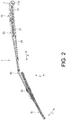
- FIG. 2 shows the AS side wiper arm 1b, and because the DR side wiper arm 1a and the AS side wiper arm 1b have the same configuration, only the AS side wiper arm 1a is described below. Further, in the description of the AS side wiper arm 1a, configuration parts of the AS side wiper arm are simply referred to as "wiper arm 1" and the like without adding "AS side", and symbol suffixes "a, b" distinguished by the DR side and the AS side are omitted.
- the wiper arm 1 includes an arm head 10 rotatable around a pivot shaft 9 provided on a vehicle body 100, and a shank 20 connected to the arm head 10.
- the arm head 10 and the shank 20 are formed into an elongated shape extending in one direction.
- the one direction is referred to as longitudinal direction X.
- the arm head 10 has a fastening part 11 having a fastening hole 11A into which the pivot shaft 9 is inserted.
- the fastening part 11 is arranged at one end of the arm head 10 in the longitudinal direction X.
- One end of the shank 20 in the longitudinal direction X is connected to the other end of the arm head 10 in the longitudinal direction X.
- an arm piece 30 is fixed.
- the arm piece 30 is formed into an elongated shape extending in the longitudinal direction X.
- One end of the arm piece 30 in the longitudinal direction X (base end part) is fixed to the shank 20.
- the arm piece 30 is fixed to the shank 20 by caulking the other end of the shank 20 in the longitudinal direction X.
- a wiper blade 40 which wipes a wiping surface S (refer to FIG. 1 ) is connected to the other end of the arm piece 30 in the longitudinal direction X (front end part).
- the wiper blade 40 is formed into an elongated shape extending in the longitudinal direction X.
- the wiping surface S is, for example, a windshield arranged in the front of a vehicle.
- a direction along a normal line of the wiping surface S is referred to as a vertical direction Y, and in the vertical direction Y, the wiper arm 1 side viewed from the wiping surface S is set as the upper side. Further, a direction orthogonal to the vertical direction Y and the longitudinal direction X is referred to as a wiping direction Z of the wiper blade 40.
- a washer nozzle 50 that sprays a washer liquid onto the wiping surface S is mounted on the base end side of a connection portion of the arm piece 30 with the wiper blade 40.
- a hose 60 that supplies the washer liquid to the washer nozzle 50 is connected to the washer nozzle 50, and the hose 60 is disposed along the arm piece 30.
- the hose 60 is divided into a first hose 61 disposed along the arm head 10 and a second hose 62 disposed inside the vehicle body 100.
- the first hose 61 is connected to the washer nozzle 50
- the second hose 62 is connected to a washer tank (not shown) in the vehicle body 100.
- the washer tank is filled with the washer liquid.
- the joint member 70 is made of, for example, a synthetic resin material.
- the joint member 70 is mounted on the arm head 10 side by side with the fastening part 11 in a manner of penetrating the arm head 10. More specifically, the arm head 10 has an opening part 10A (refer to FIG. 8 and FIG. 11 ) that opens on the fastening part 11 side, and the joint member 70 is mounted on the arm head 10 in a manner that a connection part of the joint member 70 with the second hose 62 penetrates the opening part 10A.
- shank 20 is rotatable (rock back) around the connection portion with the arm head 10 toward a direction away from the wiping surface S.
- the shank 20 and the arm head 10 are connected to each other by a coil spring 21.
- a hose housing part 12 which houses the first hose 61 is formed in the arm head 10.
- the hose housing part 12 is formed into a groove shape that is recessed toward the upper side and extends along the longitudinal direction X on the inner surface of the arm head 10.
- engagement protrusions 12A that protrude toward the inside of the hose housing part 12 in the wiping direction Z are formed.
- a plurality of engagement protrusions 12A are formed at intervals in the longitudinal direction X.
- the engagement protrusions 12A are formed at two locations spaced apart from each other in the longitudinal direction X. The first hose 61 is held in the hose housing part 12 by being sandwiched between the engagement protrusions 12A from both sides in the wiping direction Z.
- the arm head 10 is provided with a joint member housing part 13 which is formed in a manner of penetrating the arm head 10 and is capable of housing the joint member 70.
- a step part 14 whose position in the vertical direction Y changes is formed in a part of the arm head 10 which is continuous with the fastening part 11 in the longitudinal direction X.
- the joint member housing part 13 is formed in a manner of penetrating the step part 14 in the longitudinal direction.
- the joint member housing part 13 is formed to be larger than the hose housing part 12 in the wiping direction Z.
- the joint member housing part 13 includes a mounting part 13A which is located on one side in the longitudinal direction X and houses the joint member 70, and a temporary mounting part 13B which is located on the other side in the longitudinal direction X and temporarily mounts the joint member 70.
- the temporary mounting part 13B is formed to be larger than the mounting part 13A in the wiping direction Z.
- the size of the temporary mounting part 13B in the wiping direction Z gradually increases from the end of one side of the longitudinal direction X toward the other side.
- a pair of engaged parts 13C that are recessed outward in the wiping direction Z are formed in a part of the mounting part 13A which is continuous with the temporary mounting part 13B in the longitudinal direction X.
- a top wall part 13D arranged on a side opposite to the wiping surface S with respect to the joint member, and a support wall part 13E facing the top wall part 13D are formed in the joint member housing part 13.
- the joint member 70 is held in a manner of being sandwiched between the top wall part 13D and the support wall part 13E.
- inner walls of the joint member housing part 13 is formed by the top wall part 13D, the support wall part 13E, and a pair of side wall parts 13F.
- engaging parts 71 that engage with the engaged parts 13C of the joint member housing part 13 are formed on the side surface of the joint member 70 directed to the wiping direction Z.
- a pair of snap fits is formed as the engaging parts 71.
- the engaging parts 71 gradually extends outward in the wiping direction Z from one side of the longitudinal direction X toward the other side on the side surface of the joint member 70.
- the joint member 70 is formed into a rectangular parallelepiped shape extending in the longitudinal direction X.
- two end surfaces directed to both outer sides of the longitudinal direction X are provided with hose connection parts 72, 73 respectively.
- the hose connection parts 72, 73 are constituted by the first hose connection part 72 arranged on a surface directed to the other side of the longitudinal direction X and the second hose connection part 73 arranged on a surface directed to one side of the longitudinal direction X, the surfaces being the outer surfaces of the joint member 70.
- the first hose 61 is connected to the first hose connection part 72
- the second hose 62 is connected to the second hose connection part 73.
- Each of the first hose connection part 72 and the second hose connection part 73 is formed into a hollow shaft shape protruding outward in the longitudinal direction X with respect to the joint member 70.
- the first hose connection part 72 is press-fitted inside the first hose 61 and the second hose connection part 73 is press-fitted inside the second hose 62.
- Fall-out prevention parts 74 are formed separately on the front end part of the first hose connection part 72 and the front end part of the second hose connection part 73, the fall-out prevention parts 74 protruding outward in the radial direction with respect to central axes of the first hose connection part 72 and the second hose connection part 73, and curbing the fall-out of the hoses 60 connected to the connection parts.
- the first hose connection part 72 extends substantially parallel to a central axis of the joint member 70 in the longitudinal direction X.
- the second hose connection part 73 is inclined with respect to the central axis. That is, the second hose connection part 73 gradually extends upwardly toward one side of the longitudinal direction X. Therefore, as shown in FIG. 7 , the second hose 62 which is connected to the second hose connection part 73 is connected to the inside of the vehicle body 100 through the upper side of the fastening part 11.
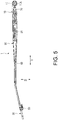
- the procedure for housing the joint member 70 into the joint member housing part 13 is described with reference to FIG. 6 .
- the joint member 70 is housed in the temporary mounting part 13B of the joint member housing part 13.
- the temporary mounting part 13B is formed larger than the mounting part 13A in the wiping direction Z, the engaging part 71 of the joint member 70 can be prevented from interfering with the side wall part of the joint member housing part 13 directed to the wiping direction Z.
- the joint member 70 is slid toward one side of the longitudinal direction X housed in the mounting part 13A.
- the engaging part 71 of the joint member 70 is elastically deformed inward in the wiping direction Z and is housed in the engaged part 13C of the mounting part 13A.
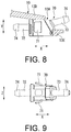
- the engaging part 71 engages with the engaged part 13C in the longitudinal direction X by being restored and deformed outward in the wiping direction Z in the engaged part 13C. Further, as shown in FIG. 8 , the joint member 70 is held in a manner of being sandwiched by the top wall part 13D and the support wall part 13E in the vertical direction Y. Finally, the first hose 61 is connected to the first hose connection part 72 of the joint member 70, and the second hose 62 is connected to the second hose connection part 73 of the joint member 70.
- the behavior of the second hose 62 when the arm head 10 is rotated around the pivot shaft 9 is described.
- the second hose 62 is deformed in the rotating direction of the arm head 10 above the fastening part 11, centering on the part connected to the inside of the vehicle body 100.
- the second hose 62 is overlapped with the rotation center of the arm head 10 in the vertical direction Y and deforms, thus the second hose 62 does not get caught on the pivot shaft 9, so that the change in the length of the second hose 62 can be suppressed before and after the rotation of the arm head 10.
- the hose 60 is divided into the first hose 61 and the second hose 62, which are connected by the joint member 70.
- the arm head 10 is provided with the opening part 10A which opens on the fastening part 11 side, and the joint member 70 is mounted in the manner that the connection part of the joint member 70 with the second hose 62 penetrates the opening part 10A. Therefore, the hose 60 can be disposed overlapping the pivot shaft 9 in the height direction along the normal line of the wiping surface S.
- the second hose 62 to interfere with the pivot shaft 9 when the arm head 10 rotates. Therefore, the length at which the hose 60 is dragged is not prone to change, it is possible to prevent the hose 60 from being stretched or entangled in the fastening part 11, and it is possible to effectively curb slack in the hose 60.
- the first hose 61 is held by being clamped in a holding part of the hose housing part 12 in the wiping direction Z. Therefore, when the shank 20 is rotated (rock back) toward the direction away from the wiping surface S with respect to the arm head 10, it is possible to curb the slack in the first hose 61 more effectively. Further, because the engaging parts 71 are formed in the joint member 70, the movement of the joint member 70 toward a direction along the longitudinal direction X of the arm head 10 can be restricted.
- joint member 70 is held in the manner of being sandwiched between the top wall part 13D and the support wall part 13E which are formed in the joint member housing part 13, it is possible to prevent the joint member 70 from being displaced in the height direction along the normal line of the wiping surface S with respect to the joint member housing part 13.
- joint member 70 can be fixed by using the joint member housing part 13, it is not necessary to arrange another engaging part in the arm head 10, and the manufacturing cost can be reduced.
- the hose 60 is sandwiched and held in the hose housing part 12 from both sides in the wiping direction Z in the above embodiment, the present invention is not limited thereto.
- the hose 60 may be housed without being sandwiched in the hose housing part 12.
- the engaging part 71 which engages with the engaged part 13C formed in the joint member housing part 13 is formed in the joint member 70 in the above embodiment, the present invention is not limited thereto.
- the engaging part 71 may not be formed on the joint member 70.
- top wall part 13D and the support wall part 13E are formed in the joint member housing part 13 and the joint member 70 is held by the top wall part 13D and the support wall part 13E in the above embodiment, the present invention is not limited thereto.
- the top wall part 13D and the support wall part 13E may not be formed in the joint member housing part 13.
Landscapes
- Engineering & Computer Science (AREA)
- Mechanical Engineering (AREA)
- Water Supply & Treatment (AREA)
- Supports For Pipes And Cables (AREA)
- Vehicle Cleaning, Maintenance, Repair, Refitting, And Outriggers (AREA)
Applications Claiming Priority (2)
| Application Number | Priority Date | Filing Date | Title |
|---|---|---|---|
| JP2018037537A JP6936753B2 (ja) | 2018-03-02 | 2018-03-02 | ワイパアーム |
| PCT/JP2019/006330 WO2019167758A1 (fr) | 2018-03-02 | 2019-02-20 | Bras d'essuie-glace |
Publications (3)
| Publication Number | Publication Date |
|---|---|
| EP3760497A1 true EP3760497A1 (fr) | 2021-01-06 |
| EP3760497A4 EP3760497A4 (fr) | 2021-11-17 |
| EP3760497B1 EP3760497B1 (fr) | 2024-03-13 |
Family
ID=67805808
Family Applications (1)
| Application Number | Title | Priority Date | Filing Date |
|---|---|---|---|
| EP19760940.7A Active EP3760497B1 (fr) | 2018-03-02 | 2019-02-20 | Bras d'essuie-glace |
Country Status (5)
| Country | Link |
|---|---|
| US (1) | US11230270B2 (fr) |
| EP (1) | EP3760497B1 (fr) |
| JP (1) | JP6936753B2 (fr) |
| CN (1) | CN111836743B (fr) |
| WO (1) | WO2019167758A1 (fr) |
Family Cites Families (10)
| Publication number | Priority date | Publication date | Assignee | Title |
|---|---|---|---|---|
| JPS56168451U (fr) * | 1980-05-16 | 1981-12-12 | ||
| JPS56168451A (en) | 1980-05-28 | 1981-12-24 | Sanyo Electric Co Ltd | Receiver of am stereophonic broadcast |
| DE4029343A1 (de) * | 1990-09-15 | 1992-03-19 | Swf Auto Electric Gmbh | Wischarm, insbesondere fuer kraftfahrzeuge |
| JP2925377B2 (ja) | 1991-09-03 | 1999-07-28 | キヤノン株式会社 | 画像形成装置 |
| JP2605107Y2 (ja) * | 1992-01-22 | 2000-06-26 | 株式会社ミツバ | ワイパアームにおけるウオツシヤホースの配設構造 |
| JP2007196724A (ja) * | 2006-01-23 | 2007-08-09 | Mitsuba Corp | ワイパ装置 |
| JP6145390B2 (ja) * | 2013-11-12 | 2017-06-14 | アスモ株式会社 | ワイパアーム及びこれを備えた車両用ワイパ装置並びにホースジョイント |
| WO2016167090A1 (fr) * | 2015-04-17 | 2016-10-20 | 株式会社ミツバ | Système d'essuie-glace |
| JP6441155B2 (ja) | 2015-04-17 | 2018-12-19 | 株式会社ミツバ | ワイパ装置 |
| FR3035631B1 (fr) * | 2015-04-28 | 2017-04-21 | Peugeot Citroen Automobiles Sa | Dispositif d’essuyage d’une surface vitree dote d’un systeme de projection de liquide de lavage a raccordement facilite |
-
2018
- 2018-03-02 JP JP2018037537A patent/JP6936753B2/ja active Active
-
2019
- 2019-02-20 EP EP19760940.7A patent/EP3760497B1/fr active Active
- 2019-02-20 CN CN201980016897.8A patent/CN111836743B/zh active Active
- 2019-02-20 WO PCT/JP2019/006330 patent/WO2019167758A1/fr not_active Ceased
- 2019-02-20 US US16/977,459 patent/US11230270B2/en active Active
Also Published As
| Publication number | Publication date |
|---|---|
| JP6936753B2 (ja) | 2021-09-22 |
| EP3760497B1 (fr) | 2024-03-13 |
| JP2019151204A (ja) | 2019-09-12 |
| WO2019167758A1 (fr) | 2019-09-06 |
| US20210078543A1 (en) | 2021-03-18 |
| CN111836743B (zh) | 2023-08-22 |
| EP3760497A4 (fr) | 2021-11-17 |
| US11230270B2 (en) | 2022-01-25 |
| CN111836743A (zh) | 2020-10-27 |
Similar Documents
| Publication | Publication Date | Title |
|---|---|---|
| RU2565434C2 (ru) | Стеклоочистительное устройство для лобового стекла | |
| US6718594B1 (en) | Wiping device for the glass surfaces of motor vehicles, comprising a wiping arm that can be moved between reversible positions and that is loaded towards the glass surface | |
| KR100968235B1 (ko) | 와이퍼 블레이드용 결합부재 및 와이퍼 블레이드 | |
| US20050017533A1 (en) | Wiper system for a window of a motor vehicle | |
| US10625714B2 (en) | Wiper device | |
| US20140173846A1 (en) | Drive member, device for holding a pipe, in particular for windscreen washer liquid, and corresponding wiper system | |
| JP2006007971A (ja) | ワイパ装置 | |
| US20170197594A1 (en) | Adapter, nozzle structure, assembly consisting of the adapter and the nozzle structure and the assembling method thereof | |
| JP2007125946A (ja) | 車両用ワイパ | |
| CN108430840A (zh) | 刮水器装置 | |
| EP3760497A1 (fr) | Bras d'essuie-glace | |
| JP4421749B2 (ja) | ウォッシャノズル付ワイパ | |
| US11220242B2 (en) | Windshield wiper arm | |
| US20230009106A1 (en) | Windscreen wiper device of the flat blade type | |
| JP2017206118A (ja) | 車両用ワイパ装置 | |
| CN108657128B (zh) | 用于自主车辆的风挡玻璃雨刮臂和帽 | |
| JP2016078582A (ja) | 車両用ワイパ | |
| JP2016203713A (ja) | ワイパ装置 | |
| JP2016203712A (ja) | ワイパ装置 | |
| CN102101400A (zh) | 波纹管的标记装置以及波纹管的标记方法 | |
| EP3746339A1 (fr) | Bras d'essuie-glace, en particulier pour automobiles | |
| JP6500946B2 (ja) | ワイパアーム及びこれを備えた車両用ワイパ装置 | |
| US20250091550A1 (en) | Wiper arm, wiper and vehicle | |
| WO2023284956A1 (fr) | Bras d'essuie-glace | |
| JP2008025797A (ja) | ホースプロテクタおよび車両用ウォッシャホース配索構造 |
Legal Events
| Date | Code | Title | Description |
|---|---|---|---|
| STAA | Information on the status of an ep patent application or granted ep patent |
Free format text: STATUS: THE INTERNATIONAL PUBLICATION HAS BEEN MADE |
|
| PUAI | Public reference made under article 153(3) epc to a published international application that has entered the european phase |
Free format text: ORIGINAL CODE: 0009012 |
|
| STAA | Information on the status of an ep patent application or granted ep patent |
Free format text: STATUS: REQUEST FOR EXAMINATION WAS MADE |
|
| 17P | Request for examination filed |
Effective date: 20200901 |
|
| AK | Designated contracting states |
Kind code of ref document: A1 Designated state(s): AL AT BE BG CH CY CZ DE DK EE ES FI FR GB GR HR HU IE IS IT LI LT LU LV MC MK MT NL NO PL PT RO RS SE SI SK SM TR |
|
| AX | Request for extension of the european patent |
Extension state: BA ME |
|
| DAV | Request for validation of the european patent (deleted) | ||
| DAX | Request for extension of the european patent (deleted) | ||
| REG | Reference to a national code |
Ref country code: DE Ref legal event code: R079 Free format text: PREVIOUS MAIN CLASS: B60S0001460000 Ipc: B60S0001340000 Ref country code: DE Ref legal event code: R079 Ref document number: 602019048241 Country of ref document: DE Free format text: PREVIOUS MAIN CLASS: B60S0001460000 Ipc: B60S0001340000 |
|
| A4 | Supplementary search report drawn up and despatched |
Effective date: 20211020 |
|
| RIC1 | Information provided on ipc code assigned before grant |
Ipc: B60S 1/52 20060101ALI20211014BHEP Ipc: B60S 1/34 20060101AFI20211014BHEP |
|
| STAA | Information on the status of an ep patent application or granted ep patent |
Free format text: STATUS: EXAMINATION IS IN PROGRESS |
|
| 17Q | First examination report despatched |
Effective date: 20230209 |
|
| GRAP | Despatch of communication of intention to grant a patent |
Free format text: ORIGINAL CODE: EPIDOSNIGR1 |
|
| STAA | Information on the status of an ep patent application or granted ep patent |
Free format text: STATUS: GRANT OF PATENT IS INTENDED |
|
| INTG | Intention to grant announced |
Effective date: 20231206 |
|
| GRAS | Grant fee paid |
Free format text: ORIGINAL CODE: EPIDOSNIGR3 |
|
| GRAA | (expected) grant |
Free format text: ORIGINAL CODE: 0009210 |
|
| STAA | Information on the status of an ep patent application or granted ep patent |
Free format text: STATUS: THE PATENT HAS BEEN GRANTED |
|
| AK | Designated contracting states |
Kind code of ref document: B1 Designated state(s): AL AT BE BG CH CY CZ DE DK EE ES FI FR GB GR HR HU IE IS IT LI LT LU LV MC MK MT NL NO PL PT RO RS SE SI SK SM TR |
|
| REG | Reference to a national code |
Ref country code: GB Ref legal event code: FG4D |
|
| REG | Reference to a national code |
Ref country code: CH Ref legal event code: EP |
|
| REG | Reference to a national code |
Ref country code: DE Ref legal event code: R096 Ref document number: 602019048241 Country of ref document: DE |
|
| REG | Reference to a national code |
Ref country code: IE Ref legal event code: FG4D |
|
| PG25 | Lapsed in a contracting state [announced via postgrant information from national office to epo] |
Ref country code: LT Free format text: LAPSE BECAUSE OF FAILURE TO SUBMIT A TRANSLATION OF THE DESCRIPTION OR TO PAY THE FEE WITHIN THE PRESCRIBED TIME-LIMIT Effective date: 20240313 |
|
| REG | Reference to a national code |
Ref country code: LT Ref legal event code: MG9D |
|
| PG25 | Lapsed in a contracting state [announced via postgrant information from national office to epo] |
Ref country code: GR Free format text: LAPSE BECAUSE OF FAILURE TO SUBMIT A TRANSLATION OF THE DESCRIPTION OR TO PAY THE FEE WITHIN THE PRESCRIBED TIME-LIMIT Effective date: 20240614 |
|
| REG | Reference to a national code |
Ref country code: NL Ref legal event code: MP Effective date: 20240313 |
|
| PG25 | Lapsed in a contracting state [announced via postgrant information from national office to epo] |
Ref country code: RS Free format text: LAPSE BECAUSE OF FAILURE TO SUBMIT A TRANSLATION OF THE DESCRIPTION OR TO PAY THE FEE WITHIN THE PRESCRIBED TIME-LIMIT Effective date: 20240613 Ref country code: HR Free format text: LAPSE BECAUSE OF FAILURE TO SUBMIT A TRANSLATION OF THE DESCRIPTION OR TO PAY THE FEE WITHIN THE PRESCRIBED TIME-LIMIT Effective date: 20240313 |
|
| PG25 | Lapsed in a contracting state [announced via postgrant information from national office to epo] |
Ref country code: ES Free format text: LAPSE BECAUSE OF FAILURE TO SUBMIT A TRANSLATION OF THE DESCRIPTION OR TO PAY THE FEE WITHIN THE PRESCRIBED TIME-LIMIT Effective date: 20240313 |
|
| PG25 | Lapsed in a contracting state [announced via postgrant information from national office to epo] |
Ref country code: RS Free format text: LAPSE BECAUSE OF FAILURE TO SUBMIT A TRANSLATION OF THE DESCRIPTION OR TO PAY THE FEE WITHIN THE PRESCRIBED TIME-LIMIT Effective date: 20240613 Ref country code: NO Free format text: LAPSE BECAUSE OF FAILURE TO SUBMIT A TRANSLATION OF THE DESCRIPTION OR TO PAY THE FEE WITHIN THE PRESCRIBED TIME-LIMIT Effective date: 20240613 Ref country code: LT Free format text: LAPSE BECAUSE OF FAILURE TO SUBMIT A TRANSLATION OF THE DESCRIPTION OR TO PAY THE FEE WITHIN THE PRESCRIBED TIME-LIMIT Effective date: 20240313 Ref country code: HR Free format text: LAPSE BECAUSE OF FAILURE TO SUBMIT A TRANSLATION OF THE DESCRIPTION OR TO PAY THE FEE WITHIN THE PRESCRIBED TIME-LIMIT Effective date: 20240313 Ref country code: GR Free format text: LAPSE BECAUSE OF FAILURE TO SUBMIT A TRANSLATION OF THE DESCRIPTION OR TO PAY THE FEE WITHIN THE PRESCRIBED TIME-LIMIT Effective date: 20240614 Ref country code: FI Free format text: LAPSE BECAUSE OF FAILURE TO SUBMIT A TRANSLATION OF THE DESCRIPTION OR TO PAY THE FEE WITHIN THE PRESCRIBED TIME-LIMIT Effective date: 20240313 Ref country code: ES Free format text: LAPSE BECAUSE OF FAILURE TO SUBMIT A TRANSLATION OF THE DESCRIPTION OR TO PAY THE FEE WITHIN THE PRESCRIBED TIME-LIMIT Effective date: 20240313 Ref country code: BG Free format text: LAPSE BECAUSE OF FAILURE TO SUBMIT A TRANSLATION OF THE DESCRIPTION OR TO PAY THE FEE WITHIN THE PRESCRIBED TIME-LIMIT Effective date: 20240313 |
|
| REG | Reference to a national code |
Ref country code: AT Ref legal event code: MK05 Ref document number: 1665481 Country of ref document: AT Kind code of ref document: T Effective date: 20240313 |
|
| PG25 | Lapsed in a contracting state [announced via postgrant information from national office to epo] |
Ref country code: SE Free format text: LAPSE BECAUSE OF FAILURE TO SUBMIT A TRANSLATION OF THE DESCRIPTION OR TO PAY THE FEE WITHIN THE PRESCRIBED TIME-LIMIT Effective date: 20240313 Ref country code: LV Free format text: LAPSE BECAUSE OF FAILURE TO SUBMIT A TRANSLATION OF THE DESCRIPTION OR TO PAY THE FEE WITHIN THE PRESCRIBED TIME-LIMIT Effective date: 20240313 |
|
| PG25 | Lapsed in a contracting state [announced via postgrant information from national office to epo] |
Ref country code: NL Free format text: LAPSE BECAUSE OF FAILURE TO SUBMIT A TRANSLATION OF THE DESCRIPTION OR TO PAY THE FEE WITHIN THE PRESCRIBED TIME-LIMIT Effective date: 20240313 |
|
| PG25 | Lapsed in a contracting state [announced via postgrant information from national office to epo] |
Ref country code: NL Free format text: LAPSE BECAUSE OF FAILURE TO SUBMIT A TRANSLATION OF THE DESCRIPTION OR TO PAY THE FEE WITHIN THE PRESCRIBED TIME-LIMIT Effective date: 20240313 |
|
| PG25 | Lapsed in a contracting state [announced via postgrant information from national office to epo] |
Ref country code: IS Free format text: LAPSE BECAUSE OF FAILURE TO SUBMIT A TRANSLATION OF THE DESCRIPTION OR TO PAY THE FEE WITHIN THE PRESCRIBED TIME-LIMIT Effective date: 20240713 |
|
| PG25 | Lapsed in a contracting state [announced via postgrant information from national office to epo] |
Ref country code: SM Free format text: LAPSE BECAUSE OF FAILURE TO SUBMIT A TRANSLATION OF THE DESCRIPTION OR TO PAY THE FEE WITHIN THE PRESCRIBED TIME-LIMIT Effective date: 20240313 Ref country code: PT Free format text: LAPSE BECAUSE OF FAILURE TO SUBMIT A TRANSLATION OF THE DESCRIPTION OR TO PAY THE FEE WITHIN THE PRESCRIBED TIME-LIMIT Effective date: 20240715 |
|
| PG25 | Lapsed in a contracting state [announced via postgrant information from national office to epo] |
Ref country code: CZ Free format text: LAPSE BECAUSE OF FAILURE TO SUBMIT A TRANSLATION OF THE DESCRIPTION OR TO PAY THE FEE WITHIN THE PRESCRIBED TIME-LIMIT Effective date: 20240313 Ref country code: EE Free format text: LAPSE BECAUSE OF FAILURE TO SUBMIT A TRANSLATION OF THE DESCRIPTION OR TO PAY THE FEE WITHIN THE PRESCRIBED TIME-LIMIT Effective date: 20240313 |
|
| PG25 | Lapsed in a contracting state [announced via postgrant information from national office to epo] |
Ref country code: AT Free format text: LAPSE BECAUSE OF FAILURE TO SUBMIT A TRANSLATION OF THE DESCRIPTION OR TO PAY THE FEE WITHIN THE PRESCRIBED TIME-LIMIT Effective date: 20240313 |
|
| PG25 | Lapsed in a contracting state [announced via postgrant information from national office to epo] |
Ref country code: PL Free format text: LAPSE BECAUSE OF FAILURE TO SUBMIT A TRANSLATION OF THE DESCRIPTION OR TO PAY THE FEE WITHIN THE PRESCRIBED TIME-LIMIT Effective date: 20240313 |
|
| PG25 | Lapsed in a contracting state [announced via postgrant information from national office to epo] |
Ref country code: SK Free format text: LAPSE BECAUSE OF FAILURE TO SUBMIT A TRANSLATION OF THE DESCRIPTION OR TO PAY THE FEE WITHIN THE PRESCRIBED TIME-LIMIT Effective date: 20240313 |
|
| PG25 | Lapsed in a contracting state [announced via postgrant information from national office to epo] |
Ref country code: SM Free format text: LAPSE BECAUSE OF FAILURE TO SUBMIT A TRANSLATION OF THE DESCRIPTION OR TO PAY THE FEE WITHIN THE PRESCRIBED TIME-LIMIT Effective date: 20240313 Ref country code: SK Free format text: LAPSE BECAUSE OF FAILURE TO SUBMIT A TRANSLATION OF THE DESCRIPTION OR TO PAY THE FEE WITHIN THE PRESCRIBED TIME-LIMIT Effective date: 20240313 Ref country code: RO Free format text: LAPSE BECAUSE OF FAILURE TO SUBMIT A TRANSLATION OF THE DESCRIPTION OR TO PAY THE FEE WITHIN THE PRESCRIBED TIME-LIMIT Effective date: 20240313 Ref country code: PT Free format text: LAPSE BECAUSE OF FAILURE TO SUBMIT A TRANSLATION OF THE DESCRIPTION OR TO PAY THE FEE WITHIN THE PRESCRIBED TIME-LIMIT Effective date: 20240715 Ref country code: PL Free format text: LAPSE BECAUSE OF FAILURE TO SUBMIT A TRANSLATION OF THE DESCRIPTION OR TO PAY THE FEE WITHIN THE PRESCRIBED TIME-LIMIT Effective date: 20240313 Ref country code: IS Free format text: LAPSE BECAUSE OF FAILURE TO SUBMIT A TRANSLATION OF THE DESCRIPTION OR TO PAY THE FEE WITHIN THE PRESCRIBED TIME-LIMIT Effective date: 20240713 Ref country code: EE Free format text: LAPSE BECAUSE OF FAILURE TO SUBMIT A TRANSLATION OF THE DESCRIPTION OR TO PAY THE FEE WITHIN THE PRESCRIBED TIME-LIMIT Effective date: 20240313 Ref country code: CZ Free format text: LAPSE BECAUSE OF FAILURE TO SUBMIT A TRANSLATION OF THE DESCRIPTION OR TO PAY THE FEE WITHIN THE PRESCRIBED TIME-LIMIT Effective date: 20240313 Ref country code: AT Free format text: LAPSE BECAUSE OF FAILURE TO SUBMIT A TRANSLATION OF THE DESCRIPTION OR TO PAY THE FEE WITHIN THE PRESCRIBED TIME-LIMIT Effective date: 20240313 |
|
| PG25 | Lapsed in a contracting state [announced via postgrant information from national office to epo] |
Ref country code: IT Free format text: LAPSE BECAUSE OF FAILURE TO SUBMIT A TRANSLATION OF THE DESCRIPTION OR TO PAY THE FEE WITHIN THE PRESCRIBED TIME-LIMIT Effective date: 20240313 |
|
| REG | Reference to a national code |
Ref country code: DE Ref legal event code: R097 Ref document number: 602019048241 Country of ref document: DE |
|
| PG25 | Lapsed in a contracting state [announced via postgrant information from national office to epo] |
Ref country code: IT Free format text: LAPSE BECAUSE OF FAILURE TO SUBMIT A TRANSLATION OF THE DESCRIPTION OR TO PAY THE FEE WITHIN THE PRESCRIBED TIME-LIMIT Effective date: 20240313 |
|
| PG25 | Lapsed in a contracting state [announced via postgrant information from national office to epo] |
Ref country code: DK Free format text: LAPSE BECAUSE OF FAILURE TO SUBMIT A TRANSLATION OF THE DESCRIPTION OR TO PAY THE FEE WITHIN THE PRESCRIBED TIME-LIMIT Effective date: 20240313 |
|
| PLBE | No opposition filed within time limit |
Free format text: ORIGINAL CODE: 0009261 |
|
| STAA | Information on the status of an ep patent application or granted ep patent |
Free format text: STATUS: NO OPPOSITION FILED WITHIN TIME LIMIT |
|
| PG25 | Lapsed in a contracting state [announced via postgrant information from national office to epo] |
Ref country code: DK Free format text: LAPSE BECAUSE OF FAILURE TO SUBMIT A TRANSLATION OF THE DESCRIPTION OR TO PAY THE FEE WITHIN THE PRESCRIBED TIME-LIMIT Effective date: 20240313 |
|
| 26N | No opposition filed |
Effective date: 20241216 |
|
| PG25 | Lapsed in a contracting state [announced via postgrant information from national office to epo] |
Ref country code: SI Free format text: LAPSE BECAUSE OF FAILURE TO SUBMIT A TRANSLATION OF THE DESCRIPTION OR TO PAY THE FEE WITHIN THE PRESCRIBED TIME-LIMIT Effective date: 20240313 |
|
| PG25 | Lapsed in a contracting state [announced via postgrant information from national office to epo] |
Ref country code: MC Free format text: LAPSE BECAUSE OF FAILURE TO SUBMIT A TRANSLATION OF THE DESCRIPTION OR TO PAY THE FEE WITHIN THE PRESCRIBED TIME-LIMIT Effective date: 20240313 |
|
| REG | Reference to a national code |
Ref country code: CH Ref legal event code: PL |
|
| PG25 | Lapsed in a contracting state [announced via postgrant information from national office to epo] |
Ref country code: LU Free format text: LAPSE BECAUSE OF NON-PAYMENT OF DUE FEES Effective date: 20250220 |
|
| PG25 | Lapsed in a contracting state [announced via postgrant information from national office to epo] |
Ref country code: CH Free format text: LAPSE BECAUSE OF NON-PAYMENT OF DUE FEES Effective date: 20250228 |
|
| GBPC | Gb: european patent ceased through non-payment of renewal fee |
Effective date: 20250220 |
|
| REG | Reference to a national code |
Ref country code: BE Ref legal event code: MM Effective date: 20250228 |
|
| PG25 | Lapsed in a contracting state [announced via postgrant information from national office to epo] |
Ref country code: GB Free format text: LAPSE BECAUSE OF NON-PAYMENT OF DUE FEES Effective date: 20250220 |
|
| PG25 | Lapsed in a contracting state [announced via postgrant information from national office to epo] |
Ref country code: FR Free format text: LAPSE BECAUSE OF NON-PAYMENT OF DUE FEES Effective date: 20250228 |
|
| PG25 | Lapsed in a contracting state [announced via postgrant information from national office to epo] |
Ref country code: BE Free format text: LAPSE BECAUSE OF NON-PAYMENT OF DUE FEES Effective date: 20250228 |
|
| PG25 | Lapsed in a contracting state [announced via postgrant information from national office to epo] |
Ref country code: IE Free format text: LAPSE BECAUSE OF NON-PAYMENT OF DUE FEES Effective date: 20250220 |
|
| PGFP | Annual fee paid to national office [announced via postgrant information from national office to epo] |
Ref country code: DE Payment date: 20251230 Year of fee payment: 8 |