EP3760873A1 - Turbine pour pompe centrifuge, en particulier pour une pompe du type à turbine encastrée et pompe comportant une telle turbine - Google Patents
Turbine pour pompe centrifuge, en particulier pour une pompe du type à turbine encastrée et pompe comportant une telle turbine Download PDFInfo
- Publication number
- EP3760873A1 EP3760873A1 EP20181452.2A EP20181452A EP3760873A1 EP 3760873 A1 EP3760873 A1 EP 3760873A1 EP 20181452 A EP20181452 A EP 20181452A EP 3760873 A1 EP3760873 A1 EP 3760873A1
- Authority
- EP
- European Patent Office
- Prior art keywords
- impeller
- disc
- vanes
- curvature
- vane
- Prior art date
- Legal status (The legal status is an assumption and is not a legal conclusion. Google has not performed a legal analysis and makes no representation as to the accuracy of the status listed.)
- Granted
Links
Images



Classifications
-
- F—MECHANICAL ENGINEERING; LIGHTING; HEATING; WEAPONS; BLASTING
- F04—POSITIVE - DISPLACEMENT MACHINES FOR LIQUIDS; PUMPS FOR LIQUIDS OR ELASTIC FLUIDS
- F04D—NON-POSITIVE-DISPLACEMENT PUMPS
- F04D29/00—Details, component parts, or accessories
- F04D29/18—Rotors
- F04D29/22—Rotors specially for centrifugal pumps
- F04D29/24—Vanes
- F04D29/242—Geometry, shape
- F04D29/245—Geometry, shape for special effects
-
- F—MECHANICAL ENGINEERING; LIGHTING; HEATING; WEAPONS; BLASTING
- F04—POSITIVE - DISPLACEMENT MACHINES FOR LIQUIDS; PUMPS FOR LIQUIDS OR ELASTIC FLUIDS
- F04D—NON-POSITIVE-DISPLACEMENT PUMPS
- F04D29/00—Details, component parts, or accessories
- F04D29/18—Rotors
- F04D29/22—Rotors specially for centrifugal pumps
- F04D29/24—Vanes
- F04D29/242—Geometry, shape
-
- F—MECHANICAL ENGINEERING; LIGHTING; HEATING; WEAPONS; BLASTING
- F04—POSITIVE - DISPLACEMENT MACHINES FOR LIQUIDS; PUMPS FOR LIQUIDS OR ELASTIC FLUIDS
- F04D—NON-POSITIVE-DISPLACEMENT PUMPS
- F04D1/00—Radial-flow pumps, e.g. centrifugal pumps; Helico-centrifugal pumps
-
- F—MECHANICAL ENGINEERING; LIGHTING; HEATING; WEAPONS; BLASTING
- F04—POSITIVE - DISPLACEMENT MACHINES FOR LIQUIDS; PUMPS FOR LIQUIDS OR ELASTIC FLUIDS
- F04D—NON-POSITIVE-DISPLACEMENT PUMPS
- F04D17/00—Radial-flow pumps, e.g. centrifugal pumps; Helico-centrifugal pumps
- F04D17/08—Centrifugal pumps
-
- F—MECHANICAL ENGINEERING; LIGHTING; HEATING; WEAPONS; BLASTING
- F04—POSITIVE - DISPLACEMENT MACHINES FOR LIQUIDS; PUMPS FOR LIQUIDS OR ELASTIC FLUIDS
- F04D—NON-POSITIVE-DISPLACEMENT PUMPS
- F04D29/00—Details, component parts, or accessories
- F04D29/04—Shafts or bearings, or assemblies thereof
- F04D29/043—Shafts
-
- F—MECHANICAL ENGINEERING; LIGHTING; HEATING; WEAPONS; BLASTING
- F04—POSITIVE - DISPLACEMENT MACHINES FOR LIQUIDS; PUMPS FOR LIQUIDS OR ELASTIC FLUIDS
- F04D—NON-POSITIVE-DISPLACEMENT PUMPS
- F04D29/00—Details, component parts, or accessories
- F04D29/18—Rotors
- F04D29/22—Rotors specially for centrifugal pumps
- F04D29/2205—Conventional flow pattern
- F04D29/2216—Shape, geometry
-
- F—MECHANICAL ENGINEERING; LIGHTING; HEATING; WEAPONS; BLASTING
- F04—POSITIVE - DISPLACEMENT MACHINES FOR LIQUIDS; PUMPS FOR LIQUIDS OR ELASTIC FLUIDS
- F04D—NON-POSITIVE-DISPLACEMENT PUMPS
- F04D29/00—Details, component parts, or accessories
- F04D29/18—Rotors
- F04D29/22—Rotors specially for centrifugal pumps
- F04D29/2205—Conventional flow pattern
- F04D29/2222—Construction and assembly
-
- F—MECHANICAL ENGINEERING; LIGHTING; HEATING; WEAPONS; BLASTING
- F04—POSITIVE - DISPLACEMENT MACHINES FOR LIQUIDS; PUMPS FOR LIQUIDS OR ELASTIC FLUIDS
- F04D—NON-POSITIVE-DISPLACEMENT PUMPS
- F04D29/00—Details, component parts, or accessories
- F04D29/18—Rotors
- F04D29/22—Rotors specially for centrifugal pumps
- F04D29/2238—Special flow patterns
-
- F—MECHANICAL ENGINEERING; LIGHTING; HEATING; WEAPONS; BLASTING
- F04—POSITIVE - DISPLACEMENT MACHINES FOR LIQUIDS; PUMPS FOR LIQUIDS OR ELASTIC FLUIDS
- F04D—NON-POSITIVE-DISPLACEMENT PUMPS
- F04D29/00—Details, component parts, or accessories
- F04D29/18—Rotors
- F04D29/22—Rotors specially for centrifugal pumps
- F04D29/2238—Special flow patterns
- F04D29/2244—Free vortex
-
- F—MECHANICAL ENGINEERING; LIGHTING; HEATING; WEAPONS; BLASTING
- F04—POSITIVE - DISPLACEMENT MACHINES FOR LIQUIDS; PUMPS FOR LIQUIDS OR ELASTIC FLUIDS
- F04D—NON-POSITIVE-DISPLACEMENT PUMPS
- F04D29/00—Details, component parts, or accessories
- F04D29/18—Rotors
- F04D29/22—Rotors specially for centrifugal pumps
- F04D29/2261—Rotors specially for centrifugal pumps with special measures
- F04D29/2272—Rotors specially for centrifugal pumps with special measures for influencing flow or boundary layer
-
- F—MECHANICAL ENGINEERING; LIGHTING; HEATING; WEAPONS; BLASTING
- F04—POSITIVE - DISPLACEMENT MACHINES FOR LIQUIDS; PUMPS FOR LIQUIDS OR ELASTIC FLUIDS
- F04D—NON-POSITIVE-DISPLACEMENT PUMPS
- F04D29/00—Details, component parts, or accessories
- F04D29/18—Rotors
- F04D29/22—Rotors specially for centrifugal pumps
- F04D29/2261—Rotors specially for centrifugal pumps with special measures
- F04D29/2294—Rotors specially for centrifugal pumps with special measures for protection, e.g. against abrasion
-
- F—MECHANICAL ENGINEERING; LIGHTING; HEATING; WEAPONS; BLASTING
- F04—POSITIVE - DISPLACEMENT MACHINES FOR LIQUIDS; PUMPS FOR LIQUIDS OR ELASTIC FLUIDS
- F04D—NON-POSITIVE-DISPLACEMENT PUMPS
- F04D29/00—Details, component parts, or accessories
- F04D29/18—Rotors
- F04D29/22—Rotors specially for centrifugal pumps
- F04D29/24—Vanes
-
- F—MECHANICAL ENGINEERING; LIGHTING; HEATING; WEAPONS; BLASTING
- F04—POSITIVE - DISPLACEMENT MACHINES FOR LIQUIDS; PUMPS FOR LIQUIDS OR ELASTIC FLUIDS
- F04D—NON-POSITIVE-DISPLACEMENT PUMPS
- F04D29/00—Details, component parts, or accessories
- F04D29/26—Rotors specially for elastic fluids
- F04D29/28—Rotors specially for elastic fluids for centrifugal or helico-centrifugal pumps for radial-flow or helico-centrifugal pumps
- F04D29/281—Rotors specially for elastic fluids for centrifugal or helico-centrifugal pumps for radial-flow or helico-centrifugal pumps for fans or blowers
-
- F—MECHANICAL ENGINEERING; LIGHTING; HEATING; WEAPONS; BLASTING
- F04—POSITIVE - DISPLACEMENT MACHINES FOR LIQUIDS; PUMPS FOR LIQUIDS OR ELASTIC FLUIDS
- F04D—NON-POSITIVE-DISPLACEMENT PUMPS
- F04D29/00—Details, component parts, or accessories
- F04D29/26—Rotors specially for elastic fluids
- F04D29/28—Rotors specially for elastic fluids for centrifugal or helico-centrifugal pumps for radial-flow or helico-centrifugal pumps
- F04D29/284—Rotors specially for elastic fluids for centrifugal or helico-centrifugal pumps for radial-flow or helico-centrifugal pumps for compressors
-
- F—MECHANICAL ENGINEERING; LIGHTING; HEATING; WEAPONS; BLASTING
- F04—POSITIVE - DISPLACEMENT MACHINES FOR LIQUIDS; PUMPS FOR LIQUIDS OR ELASTIC FLUIDS
- F04D—NON-POSITIVE-DISPLACEMENT PUMPS
- F04D29/00—Details, component parts, or accessories
- F04D29/26—Rotors specially for elastic fluids
- F04D29/28—Rotors specially for elastic fluids for centrifugal or helico-centrifugal pumps for radial-flow or helico-centrifugal pumps
- F04D29/30—Vanes
-
- F—MECHANICAL ENGINEERING; LIGHTING; HEATING; WEAPONS; BLASTING
- F04—POSITIVE - DISPLACEMENT MACHINES FOR LIQUIDS; PUMPS FOR LIQUIDS OR ELASTIC FLUIDS
- F04D—NON-POSITIVE-DISPLACEMENT PUMPS
- F04D7/00—Pumps adapted for handling specific fluids, e.g. by selection of specific materials for pumps or pump parts
- F04D7/02—Pumps adapted for handling specific fluids, e.g. by selection of specific materials for pumps or pump parts of centrifugal type
- F04D7/04—Pumps adapted for handling specific fluids, e.g. by selection of specific materials for pumps or pump parts of centrifugal type the fluids being viscous or non-homogenous
-
- F—MECHANICAL ENGINEERING; LIGHTING; HEATING; WEAPONS; BLASTING
- F04—POSITIVE - DISPLACEMENT MACHINES FOR LIQUIDS; PUMPS FOR LIQUIDS OR ELASTIC FLUIDS
- F04D—NON-POSITIVE-DISPLACEMENT PUMPS
- F04D7/00—Pumps adapted for handling specific fluids, e.g. by selection of specific materials for pumps or pump parts
- F04D7/02—Pumps adapted for handling specific fluids, e.g. by selection of specific materials for pumps or pump parts of centrifugal type
- F04D7/04—Pumps adapted for handling specific fluids, e.g. by selection of specific materials for pumps or pump parts of centrifugal type the fluids being viscous or non-homogenous
- F04D7/045—Pumps adapted for handling specific fluids, e.g. by selection of specific materials for pumps or pump parts of centrifugal type the fluids being viscous or non-homogenous with means for comminuting, mixing stirring or otherwise treating
-
- F—MECHANICAL ENGINEERING; LIGHTING; HEATING; WEAPONS; BLASTING
- F05—INDEXING SCHEMES RELATING TO ENGINES OR PUMPS IN VARIOUS SUBCLASSES OF CLASSES F01-F04
- F05D—INDEXING SCHEME FOR ASPECTS RELATING TO NON-POSITIVE-DISPLACEMENT MACHINES OR ENGINES, GAS-TURBINES OR JET-PROPULSION PLANTS
- F05D2240/00—Components
- F05D2240/20—Rotors
- F05D2240/30—Characteristics of rotor blades, i.e. of any element transforming dynamic fluid energy to or from rotational energy and being attached to a rotor
- F05D2240/301—Cross-sectional characteristics
-
- F—MECHANICAL ENGINEERING; LIGHTING; HEATING; WEAPONS; BLASTING
- F05—INDEXING SCHEMES RELATING TO ENGINES OR PUMPS IN VARIOUS SUBCLASSES OF CLASSES F01-F04
- F05D—INDEXING SCHEME FOR ASPECTS RELATING TO NON-POSITIVE-DISPLACEMENT MACHINES OR ENGINES, GAS-TURBINES OR JET-PROPULSION PLANTS
- F05D2240/00—Components
- F05D2240/20—Rotors
- F05D2240/30—Characteristics of rotor blades, i.e. of any element transforming dynamic fluid energy to or from rotational energy and being attached to a rotor
- F05D2240/307—Characteristics of rotor blades, i.e. of any element transforming dynamic fluid energy to or from rotational energy and being attached to a rotor related to the tip of a rotor blade
Definitions
- the present invention relates to an impeller for centrifugal pump, particularly for centrifugal pump of the recessed impeller type.
- the invention also relates to a centrifugal pump with such an impeller.
- centrifugal pump of the recessed impeller type is understood to refer to a pump that has an impeller that is recessed with respect to the inlet of the intake duct and utilizes the generation of a single coherent vortex in front of the impeller to impart the centrifugal acceleration to the pumped liquid.
- the impeller is constituted by a substantially flat disc from which a plurality of vanes, adapted to move a liquid, extend.
- the liquid is aspirated in a direction that is normal to the plane of the disc and sent in a direction that is radial thereto.
- vanes of the impeller are mutually equidistant, have a rectilinear or curved cross-section on the disc and are extended vertically, remaining at right angles to the disc.
- impeller in the present description is understood to mean that the corresponding points of the vanes of the impeller are at a constant mutual distance between any vane and the next, on a circumference.
- end vortices form around each vane in the region in front of the impeller and are capable of modifying the trajectories of the liquid flow lines, reducing both head and pumping efficiency.
- impellers In order to reduce turbulence and improve pumping efficiency, in recent years impellers have been developed which have complementary discs, arranged opposite the discs, in order to enclose the vanes between the complementary discs and the discs.
- each vane ends with a terminal portion, which is parallel to the disc and is extended along the entire curvature of the vane.
- impellers in fact, are subject to wear and to possible impacts of pumped solid bodies, particularly against complementary discs or terminal portions of the vanes, which can damage them and compromise their operation.
- Centrifugal pumps with recessed impeller are also known in which the impeller has a disc that is shaped so as to match the profile of the external ends of the vanes or with non-equidistant vanes.
- outside of the impeller in the present description, is understood to mean that the concavity of the vanes is substantially directed toward the external circumference of the disc and/or the projection of said circumference.
- inside of the impeller in the present description, is understood instead to mean that the concavity of the vanes is substantially directed toward the internal circumference of the disc and/or the projection of said circumference.
- Such impellers which can also have a complementary disc, are adapted to maximize the flow of the liquid in the intervane channel and are designed to work proximate to a fixed surface of the pump body.
- the aim of the present invention is to provide an impeller for centrifugal pump, of the recessed impeller type, and a pump with such an impeller that are capable of improving the background art in one or more of the aspects mentioned above.
- an object of the invention is to provide an impeller for centrifugal pump, particularly for a pump of the recessed impeller type, that allows to improve the pumping efficiency and the head of the pump in which it is installed with respect to similar impellers of a known type.
- Another object of the invention is to provide an impeller for centrifugal pump, particularly for a pump of the recessed impeller type, that is less subject to wear or to impacts by solid bodies with respect to similar impellers of a known type.
- Another object of the invention is to provide an impeller for centrifugal pump, particularly for a pump of the recessed impeller type, in which the capacity to generate the vortex is maximized with respect to similar impellers of a known type.
- Another object of the invention is to provide a centrifugal pump that has an impeller capable of achieving the aim and objects described above.
- a further object of the present invention is to overcome the drawbacks of the background art in a manner that is alternative to any existing solutions.
- Another object of the invention is to provide an impeller for centrifugal pump, particularly for a pump of the recessed impeller type, that is highly reliable, relatively easy to provide and at competitive costs.
- an impeller for centrifugal pump comprising:
- the impeller for centrifugal pump according to the invention is generally designated by the reference numeral 10.
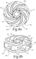
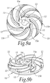
- the impeller 10 comprises a disc 11 and a plurality of vanes 12 which extends from a surface of this disc 11.
- the disc 11 is flat.
- each one of said vanes 12 has a profile with a double curvature:
- both the first curvature and the second curvature have their concavity directed toward the inside of the impeller 10.
- the impeller 10 comprises a central body 13, at the lower circumference of the disc 11, having a through hole 14 adapted for the insertion of a shaft, not shown in the figures, for its rotation.
- This central body 13 has a frustum-like shape, with the larger end face substantially at the disc 11 and the smaller end face on the same side of extension as the vanes 12.
- the height of the frustum of the central body 13 is lower than the height of the vanes 12, as shown in Figures 3 and 5 to 7 .
- the vanes 12 are equidistant and each vane 12 is extended between:
- the frustum-like shape of the central body 13 facilitates the exposure of the first end 15a of the vanes outside the influence of the central body 13. In this manner, the capacity for generating the coherent vortex in front of the impeller is increased.
- each vane 12 comprises an inside curve 16 and an outside curve 17 which have different curvatures:
- inside curve in the present description is understood to refer to the surface of the vane 12 that is directed toward the central body 13 and is substantially parallel to the lateral surface thereof.
- outside curve in the present description is understood to refer to the surface of the vane 12 that is opposite the inside curve.
- the inside curve 16 and the outside curve 17 represent two arcs of circumferences with distinct centers and/or two Non Uniform Rational Basis-Splines (NURBS) with a different number of poles and/or nodes.
- NURBS Non Uniform Rational Basis-Splines
- NURBS is understood to refer to a mathematical model commonly used in computer graphics to generate and represent curves and surfaces and well-known to the person skilled in the art.
- each vane 12 decreases uniformly from a maximum value, at the first end 15a, to a minimum value at the second end 15b.
- thickness of the vane in the present description, is understood to refer to the distance between corresponding points of the inside curve 16 and the outside curve 17.
- the thickness of the vane can be constant.
- the thickness at the first end 15a is on the order of 0.3-1 cm, for example 0.4 cm, while the thickness of the vane 12 at the second end 15b is on the order of 0.15-0.8 cm, for example 0.2 cm.
- each vane 12 also decreases uniformly from a maximum value, at the first end 15a, to a minimum value at the second end 15b.
- the height of the vane 12 at the first end 15a is, for example, on the order of 2-10 cm, for example 3 cm, while the height of the vane 12 at the second end 15b is on the order of 0.5-9 cm, for example 1.6 cm.
- Each vane 12 comprises a terminal portion 18, opposite the disc 11.
- the terminal portion 18, monolithic with the vane 12 extends from the outside curve 17 of the vane 12 toward the inside of the impeller 10 and has an extension along the entire first curvature of the vane 12.
- the terminal portion 18 has a width equal to the thickness of the vane 12, at the first end 15a, and increases in the direction of the second end 15b, in which it is greatest.
- width of the terminal portion in the present description is understood to refer to the distance between the edge of the terminal portion 18 directed toward the outside of the impeller 10, which coincides with the outside curve 17 of the vane 12, and the edge directed toward the inside of the impeller 10, which coincides with the inside curve 16 only at the first end 15a.
- the maximum width of the terminal portion 18 is on the order of 0.5-7 cm, for example 0.7 cm.
- the maximum width of the terminal portion 18 is smaller than or equal to the half-distance between the inside curve of one vane 12 and the outside curve of the next one.
- the terminal portion 18 protrudes from the inside curve 16 of the vane 12 toward the inside of the impeller 10, at least starting from a region that is proximate to the second end 15b.
- the region of the terminal portion 18 that protrudes from the inside curve 16 is extended locally in a direction X that is at right angles to the tangent T to the inside curve 16 in the point 19 of the inside curve 16 that is furthest from the disc 11, considering a sectional plane that is at right angles to the disc 11.
- the terminal portion 18 of a vane 12 does not interfere with the contribution to the generation of the vortex of the next vane and wear and possible damage caused by impacts with solid bodies are reduced.
- vanes 12 allows to improve the pumping efficiency and the head of the pump in which it is installed with respect to similar impellers of a known type.
- vanes 12, with the second curvature directed toward the inside of the impeller 10 reduce the power absorbed by the liquid, increasing the vortex generation capacity, with respect to similar impellers of a known type.
- the invention has achieved the intended aim and objects, providing an impeller for centrifugal pump, particularly for a pump of the recessed impeller type, that allows to improve the pumping efficiency and the head of the pump in which it is installed with respect to similar impellers of a known type.
- the invention provides an impeller for centrifugal pump, particularly for a pump of the recessed impeller type, that is less prone to wear or to impacts from solid bodies with respect to similar impellers of a known type and in which the capacity of generating the vortex is maximized with respect to similar impellers of a known type.
- the invention also provides a centrifugal pump that has an impeller capable of reaching the aim and objects proposed above.
- the materials used may be any according to the requirements and the state of the art.
Landscapes
- Engineering & Computer Science (AREA)
- Mechanical Engineering (AREA)
- General Engineering & Computer Science (AREA)
- Physics & Mathematics (AREA)
- Geometry (AREA)
- Structures Of Non-Positive Displacement Pumps (AREA)
Applications Claiming Priority (1)
| Application Number | Priority Date | Filing Date | Title |
|---|---|---|---|
| IT102019000010632A IT201900010632A1 (it) | 2019-07-02 | 2019-07-02 | Girante perfezionata per pompa centrifuga, particolarmente per pompa del tipo a girante arretrata, e pompa con una simile girante |
Publications (2)
| Publication Number | Publication Date |
|---|---|
| EP3760873A1 true EP3760873A1 (fr) | 2021-01-06 |
| EP3760873B1 EP3760873B1 (fr) | 2022-07-20 |
Family
ID=68426677
Family Applications (1)
| Application Number | Title | Priority Date | Filing Date |
|---|---|---|---|
| EP20181452.2A Active EP3760873B1 (fr) | 2019-07-02 | 2020-06-22 | Turbine pour pompe centrifuge du type à turbine encastrée et pompe comportant une telle turbine |
Country Status (5)
| Country | Link |
|---|---|
| US (1) | US11378091B2 (fr) |
| EP (1) | EP3760873B1 (fr) |
| CN (1) | CN112177972A (fr) |
| ES (1) | ES2925567T3 (fr) |
| IT (1) | IT201900010632A1 (fr) |
Families Citing this family (6)
| Publication number | Priority date | Publication date | Assignee | Title |
|---|---|---|---|---|
| ES2953936T3 (es) * | 2019-12-13 | 2023-11-17 | Dab Pumps Spa | Rodete para bomba centrífuga, particularmente para una bomba de rodete empotrado, y bomba con dicho rodete |
| USD958842S1 (en) * | 2020-04-04 | 2022-07-26 | Colina | Mixing pump impeller vane assembly |
| USD940760S1 (en) * | 2020-04-04 | 2022-01-11 | Colina | Mixing pump impeller |
| EP3971422B1 (fr) * | 2020-09-22 | 2024-05-15 | Xylem Europe GmbH | Roue ouverte de pompe submersible conçue pour le pompage de liquide comprenant des matières abrasives et pompe submersible comprenant ladite roue |
| DE102021110936A1 (de) | 2021-04-28 | 2022-11-03 | Herborner Pumpentechnik Gmbh & Co Kg | Pumpenlaufrad, Gehäuseelement und Pumpe hiermit |
| JP2024136594A (ja) * | 2023-03-24 | 2024-10-04 | 本田技研工業株式会社 | ラジアルタービン用インペラ |
Citations (5)
| Publication number | Priority date | Publication date | Assignee | Title |
|---|---|---|---|---|
| US3384026A (en) * | 1966-08-16 | 1968-05-21 | Itt | Pump apparatus |
| DE3305790A1 (de) * | 1983-02-19 | 1984-08-23 | Klein, Schanzlin & Becker Ag, 6710 Frankenthal | Freistrompumpe |
| US4676718A (en) * | 1984-08-16 | 1987-06-30 | Oy E. Sarlin Ab | Impeller for a pump, especially a vortex pump |
| FR2640328A1 (fr) * | 1988-12-09 | 1990-06-15 | Schlumberger Cie Dowell | Rotor a pales pour pompe du type centrifuge, pompe et melangeur en faisant application |
| EP2226505A1 (fr) * | 2009-03-03 | 2010-09-08 | KSB Aktiengesellschaft | Roue vortex dotée de bords coupants |
Family Cites Families (15)
| Publication number | Priority date | Publication date | Assignee | Title |
|---|---|---|---|---|
| US244870A (en) * | 1881-07-26 | Log-turner | ||
| US2422615A (en) * | 1941-11-21 | 1947-06-17 | Havillard Aircraft Company Ltd | Rotary compressor |
| US2350939A (en) * | 1943-04-22 | 1944-06-06 | Verner E Sprouse | Blower |
| CH478719A (de) * | 1968-11-28 | 1969-09-30 | Kaelin J R | Vertikalachsiger Belüfterkreisel zum Belüften von Flüssigkeiten, insbesondere von zu klärenden Abwässern |
| US4479757A (en) * | 1982-09-30 | 1984-10-30 | Dominion Engineering Works Limited | Blade configurations for Francis-type turbine runners |
| US5002461A (en) * | 1990-01-26 | 1991-03-26 | Schwitzer U.S. Inc. | Compressor impeller with displaced splitter blades |
| CN2345758Y (zh) * | 1998-05-13 | 1999-10-27 | 高歌 | 具有扭曲柳叶型叶片的离心泵叶轮 |
| US7198470B2 (en) * | 2003-06-16 | 2007-04-03 | Kabushiki Kaisha Toshiba | Francis turbine |
| JP4346412B2 (ja) * | 2003-10-31 | 2009-10-21 | 株式会社東芝 | タービン翼列装置 |
| JP4768361B2 (ja) * | 2005-08-29 | 2011-09-07 | 株式会社東芝 | フランシス形ランナ及び水力機械 |
| WO2008150464A1 (fr) * | 2007-06-01 | 2008-12-11 | The Gorman-Rupp Company | Pompe, et turbine de pompe |
| US7896617B1 (en) * | 2008-09-26 | 2011-03-01 | Morando Jorge A | High flow/high efficiency centrifugal pump having a turbine impeller for liquid applications including molten metal |
| FR2974394A1 (fr) * | 2011-04-20 | 2012-10-26 | Alstom Hydro France | Roue pour machine hydraulique, machine hydraulique equipee d'une telle roue et installation de conversion d'energie comprenant une telle machine hydraulique |
| CN104564716A (zh) * | 2015-01-06 | 2015-04-29 | 浙江理工大学 | 一种离心泵稳流叶轮的改进方法 |
| KR101913147B1 (ko) * | 2016-10-10 | 2018-10-30 | 소애련 | 후향 이중구배 단면 형상 깃 원심임펠러 |
-
2019
- 2019-07-02 IT IT102019000010632A patent/IT201900010632A1/it unknown
-
2020
- 2020-06-22 EP EP20181452.2A patent/EP3760873B1/fr active Active
- 2020-06-22 ES ES20181452T patent/ES2925567T3/es active Active
- 2020-07-02 CN CN202010633263.1A patent/CN112177972A/zh active Pending
- 2020-07-02 US US16/919,665 patent/US11378091B2/en active Active
Patent Citations (5)
| Publication number | Priority date | Publication date | Assignee | Title |
|---|---|---|---|---|
| US3384026A (en) * | 1966-08-16 | 1968-05-21 | Itt | Pump apparatus |
| DE3305790A1 (de) * | 1983-02-19 | 1984-08-23 | Klein, Schanzlin & Becker Ag, 6710 Frankenthal | Freistrompumpe |
| US4676718A (en) * | 1984-08-16 | 1987-06-30 | Oy E. Sarlin Ab | Impeller for a pump, especially a vortex pump |
| FR2640328A1 (fr) * | 1988-12-09 | 1990-06-15 | Schlumberger Cie Dowell | Rotor a pales pour pompe du type centrifuge, pompe et melangeur en faisant application |
| EP2226505A1 (fr) * | 2009-03-03 | 2010-09-08 | KSB Aktiengesellschaft | Roue vortex dotée de bords coupants |
Also Published As
| Publication number | Publication date |
|---|---|
| CN112177972A (zh) | 2021-01-05 |
| IT201900010632A1 (it) | 2021-01-02 |
| EP3760873B1 (fr) | 2022-07-20 |
| US20210003134A1 (en) | 2021-01-07 |
| ES2925567T3 (es) | 2022-10-18 |
| US11378091B2 (en) | 2022-07-05 |
Similar Documents
| Publication | Publication Date | Title |
|---|---|---|
| EP3760873B1 (fr) | Turbine pour pompe centrifuge du type à turbine encastrée et pompe comportant une telle turbine | |
| EP3835591B1 (fr) | Turbine pour pompe centrifuge, en particulier pour une pompe à turbine encastrée et pompe comportant une telle turbine | |
| US11236760B2 (en) | Impeller and fan | |
| EP2623794B1 (fr) | Diffuseur de compresseur centrifuge | |
| CA2837293C (fr) | Helice comportant des pales ayant un profil non lineaire | |
| US9874219B2 (en) | Impeller and fluid machine | |
| JO2510B1 (en) | Improved pump impeller | |
| MX339040B (es) | Mejoras relacionadas a rotores de bombas centrifugas. | |
| CN214464916U (zh) | 一种具有高效空间导叶的多级熔盐泵 | |
| CN107061368A (zh) | 采用周向可变叶片稠度非对称有叶扩压器的离心压气机 | |
| CN108757568B (zh) | 一种轴流风机叶片 | |
| CN207961044U (zh) | 叶轮以及具有该叶轮的离心泵 | |
| CN106704259A (zh) | 叶片 | |
| CS203144B2 (en) | Impeller for centrifugal pumps | |
| CN116379000B (zh) | 疏浚泥泵叶轮的非轴对称端壁造型 | |
| CN103939150B (zh) | 一种降低透平级气流激振力的静叶结构 | |
| CN219035115U (zh) | 混流风轮、风轮组件、混流风机及风扇 | |
| CN206943079U (zh) | 一种提高抗汽蚀性能的轴流泵叶轮 | |
| CN211144903U (zh) | 一种低噪蜗壳及离心通风机 | |
| RU144424U1 (ru) | Лопатка рабочего колеса ротора компрессора низкого давления турбореактивного двигателя | |
| CN118462642B (zh) | 一种具有抑制涡脱落槽的离心风轮 | |
| CN110513331A (zh) | 一种低噪蜗壳及离心通风机 | |
| CN106958534A (zh) | 一种提高抗汽蚀性能的轴流泵叶轮 | |
| CN104047889A (zh) | 一种消除轴流泵叶顶间隙内角涡的方法 |
Legal Events
| Date | Code | Title | Description |
|---|---|---|---|
| PUAI | Public reference made under article 153(3) epc to a published international application that has entered the european phase |
Free format text: ORIGINAL CODE: 0009012 |
|
| STAA | Information on the status of an ep patent application or granted ep patent |
Free format text: STATUS: THE APPLICATION HAS BEEN PUBLISHED |
|
| AK | Designated contracting states |
Kind code of ref document: A1 Designated state(s): AL AT BE BG CH CY CZ DE DK EE ES FI FR GB GR HR HU IE IS IT LI LT LU LV MC MK MT NL NO PL PT RO RS SE SI SK SM TR |
|
| AX | Request for extension of the european patent |
Extension state: BA ME |
|
| STAA | Information on the status of an ep patent application or granted ep patent |
Free format text: STATUS: REQUEST FOR EXAMINATION WAS MADE |
|
| 17P | Request for examination filed |
Effective date: 20210427 |
|
| RBV | Designated contracting states (corrected) |
Designated state(s): AL AT BE BG CH CY CZ DE DK EE ES FI FR GB GR HR HU IE IS IT LI LT LU LV MC MK MT NL NO PL PT RO RS SE SI SK SM TR |
|
| GRAP | Despatch of communication of intention to grant a patent |
Free format text: ORIGINAL CODE: EPIDOSNIGR1 |
|
| STAA | Information on the status of an ep patent application or granted ep patent |
Free format text: STATUS: GRANT OF PATENT IS INTENDED |
|
| INTG | Intention to grant announced |
Effective date: 20220420 |
|
| GRAS | Grant fee paid |
Free format text: ORIGINAL CODE: EPIDOSNIGR3 |
|
| GRAA | (expected) grant |
Free format text: ORIGINAL CODE: 0009210 |
|
| STAA | Information on the status of an ep patent application or granted ep patent |
Free format text: STATUS: THE PATENT HAS BEEN GRANTED |
|
| AK | Designated contracting states |
Kind code of ref document: B1 Designated state(s): AL AT BE BG CH CY CZ DE DK EE ES FI FR GB GR HR HU IE IS IT LI LT LU LV MC MK MT NL NO PL PT RO RS SE SI SK SM TR |
|
| REG | Reference to a national code |
Ref country code: CH Ref legal event code: EP |
|
| REG | Reference to a national code |
Ref country code: DE Ref legal event code: R096 Ref document number: 602020004057 Country of ref document: DE |
|
| REG | Reference to a national code |
Ref country code: AT Ref legal event code: REF Ref document number: 1505679 Country of ref document: AT Kind code of ref document: T Effective date: 20220815 |
|
| REG | Reference to a national code |
Ref country code: IE Ref legal event code: FG4D |
|
| REG | Reference to a national code |
Ref country code: ES Ref legal event code: FG2A Ref document number: 2925567 Country of ref document: ES Kind code of ref document: T3 Effective date: 20221018 |
|
| REG | Reference to a national code |
Ref country code: LT Ref legal event code: MG9D |
|
| REG | Reference to a national code |
Ref country code: NL Ref legal event code: MP Effective date: 20220720 |
|
| PG25 | Lapsed in a contracting state [announced via postgrant information from national office to epo] |
Ref country code: SE Free format text: LAPSE BECAUSE OF FAILURE TO SUBMIT A TRANSLATION OF THE DESCRIPTION OR TO PAY THE FEE WITHIN THE PRESCRIBED TIME-LIMIT Effective date: 20220720 Ref country code: RS Free format text: LAPSE BECAUSE OF FAILURE TO SUBMIT A TRANSLATION OF THE DESCRIPTION OR TO PAY THE FEE WITHIN THE PRESCRIBED TIME-LIMIT Effective date: 20220720 Ref country code: PT Free format text: LAPSE BECAUSE OF FAILURE TO SUBMIT A TRANSLATION OF THE DESCRIPTION OR TO PAY THE FEE WITHIN THE PRESCRIBED TIME-LIMIT Effective date: 20221121 Ref country code: NO Free format text: LAPSE BECAUSE OF FAILURE TO SUBMIT A TRANSLATION OF THE DESCRIPTION OR TO PAY THE FEE WITHIN THE PRESCRIBED TIME-LIMIT Effective date: 20221020 Ref country code: NL Free format text: LAPSE BECAUSE OF FAILURE TO SUBMIT A TRANSLATION OF THE DESCRIPTION OR TO PAY THE FEE WITHIN THE PRESCRIBED TIME-LIMIT Effective date: 20220720 Ref country code: LV Free format text: LAPSE BECAUSE OF FAILURE TO SUBMIT A TRANSLATION OF THE DESCRIPTION OR TO PAY THE FEE WITHIN THE PRESCRIBED TIME-LIMIT Effective date: 20220720 Ref country code: LT Free format text: LAPSE BECAUSE OF FAILURE TO SUBMIT A TRANSLATION OF THE DESCRIPTION OR TO PAY THE FEE WITHIN THE PRESCRIBED TIME-LIMIT Effective date: 20220720 Ref country code: FI Free format text: LAPSE BECAUSE OF FAILURE TO SUBMIT A TRANSLATION OF THE DESCRIPTION OR TO PAY THE FEE WITHIN THE PRESCRIBED TIME-LIMIT Effective date: 20220720 |
|
| REG | Reference to a national code |
Ref country code: AT Ref legal event code: MK05 Ref document number: 1505679 Country of ref document: AT Kind code of ref document: T Effective date: 20220720 |
|
| PG25 | Lapsed in a contracting state [announced via postgrant information from national office to epo] |
Ref country code: PL Free format text: LAPSE BECAUSE OF FAILURE TO SUBMIT A TRANSLATION OF THE DESCRIPTION OR TO PAY THE FEE WITHIN THE PRESCRIBED TIME-LIMIT Effective date: 20220720 Ref country code: IS Free format text: LAPSE BECAUSE OF FAILURE TO SUBMIT A TRANSLATION OF THE DESCRIPTION OR TO PAY THE FEE WITHIN THE PRESCRIBED TIME-LIMIT Effective date: 20221120 Ref country code: HR Free format text: LAPSE BECAUSE OF FAILURE TO SUBMIT A TRANSLATION OF THE DESCRIPTION OR TO PAY THE FEE WITHIN THE PRESCRIBED TIME-LIMIT Effective date: 20220720 Ref country code: GR Free format text: LAPSE BECAUSE OF FAILURE TO SUBMIT A TRANSLATION OF THE DESCRIPTION OR TO PAY THE FEE WITHIN THE PRESCRIBED TIME-LIMIT Effective date: 20221021 |
|
| REG | Reference to a national code |
Ref country code: DE Ref legal event code: R097 Ref document number: 602020004057 Country of ref document: DE |
|
| PG25 | Lapsed in a contracting state [announced via postgrant information from national office to epo] |
Ref country code: SM Free format text: LAPSE BECAUSE OF FAILURE TO SUBMIT A TRANSLATION OF THE DESCRIPTION OR TO PAY THE FEE WITHIN THE PRESCRIBED TIME-LIMIT Effective date: 20220720 Ref country code: RO Free format text: LAPSE BECAUSE OF FAILURE TO SUBMIT A TRANSLATION OF THE DESCRIPTION OR TO PAY THE FEE WITHIN THE PRESCRIBED TIME-LIMIT Effective date: 20220720 Ref country code: DK Free format text: LAPSE BECAUSE OF FAILURE TO SUBMIT A TRANSLATION OF THE DESCRIPTION OR TO PAY THE FEE WITHIN THE PRESCRIBED TIME-LIMIT Effective date: 20220720 Ref country code: CZ Free format text: LAPSE BECAUSE OF FAILURE TO SUBMIT A TRANSLATION OF THE DESCRIPTION OR TO PAY THE FEE WITHIN THE PRESCRIBED TIME-LIMIT Effective date: 20220720 Ref country code: AT Free format text: LAPSE BECAUSE OF FAILURE TO SUBMIT A TRANSLATION OF THE DESCRIPTION OR TO PAY THE FEE WITHIN THE PRESCRIBED TIME-LIMIT Effective date: 20220720 |
|
| PLBE | No opposition filed within time limit |
Free format text: ORIGINAL CODE: 0009261 |
|
| STAA | Information on the status of an ep patent application or granted ep patent |
Free format text: STATUS: NO OPPOSITION FILED WITHIN TIME LIMIT |
|
| PG25 | Lapsed in a contracting state [announced via postgrant information from national office to epo] |
Ref country code: SK Free format text: LAPSE BECAUSE OF FAILURE TO SUBMIT A TRANSLATION OF THE DESCRIPTION OR TO PAY THE FEE WITHIN THE PRESCRIBED TIME-LIMIT Effective date: 20220720 Ref country code: EE Free format text: LAPSE BECAUSE OF FAILURE TO SUBMIT A TRANSLATION OF THE DESCRIPTION OR TO PAY THE FEE WITHIN THE PRESCRIBED TIME-LIMIT Effective date: 20220720 |
|
| P01 | Opt-out of the competence of the unified patent court (upc) registered |
Effective date: 20230515 |
|
| 26N | No opposition filed |
Effective date: 20230421 |
|
| PG25 | Lapsed in a contracting state [announced via postgrant information from national office to epo] |
Ref country code: AL Free format text: LAPSE BECAUSE OF FAILURE TO SUBMIT A TRANSLATION OF THE DESCRIPTION OR TO PAY THE FEE WITHIN THE PRESCRIBED TIME-LIMIT Effective date: 20220720 |
|
| PG25 | Lapsed in a contracting state [announced via postgrant information from national office to epo] |
Ref country code: SI Free format text: LAPSE BECAUSE OF FAILURE TO SUBMIT A TRANSLATION OF THE DESCRIPTION OR TO PAY THE FEE WITHIN THE PRESCRIBED TIME-LIMIT Effective date: 20220720 |
|
| PG25 | Lapsed in a contracting state [announced via postgrant information from national office to epo] |
Ref country code: MC Free format text: LAPSE BECAUSE OF FAILURE TO SUBMIT A TRANSLATION OF THE DESCRIPTION OR TO PAY THE FEE WITHIN THE PRESCRIBED TIME-LIMIT Effective date: 20220720 |
|
| PG25 | Lapsed in a contracting state [announced via postgrant information from national office to epo] |
Ref country code: MC Free format text: LAPSE BECAUSE OF FAILURE TO SUBMIT A TRANSLATION OF THE DESCRIPTION OR TO PAY THE FEE WITHIN THE PRESCRIBED TIME-LIMIT Effective date: 20220720 |
|
| REG | Reference to a national code |
Ref country code: CH Ref legal event code: PL |
|
| REG | Reference to a national code |
Ref country code: BE Ref legal event code: MM Effective date: 20230630 |
|
| PG25 | Lapsed in a contracting state [announced via postgrant information from national office to epo] |
Ref country code: LU Free format text: LAPSE BECAUSE OF NON-PAYMENT OF DUE FEES Effective date: 20230622 |
|
| REG | Reference to a national code |
Ref country code: IE Ref legal event code: MM4A |
|
| PG25 | Lapsed in a contracting state [announced via postgrant information from national office to epo] |
Ref country code: LU Free format text: LAPSE BECAUSE OF NON-PAYMENT OF DUE FEES Effective date: 20230622 |
|
| PG25 | Lapsed in a contracting state [announced via postgrant information from national office to epo] |
Ref country code: IE Free format text: LAPSE BECAUSE OF NON-PAYMENT OF DUE FEES Effective date: 20230622 |
|
| PG25 | Lapsed in a contracting state [announced via postgrant information from national office to epo] |
Ref country code: IE Free format text: LAPSE BECAUSE OF NON-PAYMENT OF DUE FEES Effective date: 20230622 Ref country code: CH Free format text: LAPSE BECAUSE OF NON-PAYMENT OF DUE FEES Effective date: 20230630 |
|
| PG25 | Lapsed in a contracting state [announced via postgrant information from national office to epo] |
Ref country code: BE Free format text: LAPSE BECAUSE OF NON-PAYMENT OF DUE FEES Effective date: 20230630 |
|
| PG25 | Lapsed in a contracting state [announced via postgrant information from national office to epo] |
Ref country code: BG Free format text: LAPSE BECAUSE OF FAILURE TO SUBMIT A TRANSLATION OF THE DESCRIPTION OR TO PAY THE FEE WITHIN THE PRESCRIBED TIME-LIMIT Effective date: 20220720 |
|
| PG25 | Lapsed in a contracting state [announced via postgrant information from national office to epo] |
Ref country code: BG Free format text: LAPSE BECAUSE OF FAILURE TO SUBMIT A TRANSLATION OF THE DESCRIPTION OR TO PAY THE FEE WITHIN THE PRESCRIBED TIME-LIMIT Effective date: 20220720 |
|
| PGFP | Annual fee paid to national office [announced via postgrant information from national office to epo] |
Ref country code: DE Payment date: 20250402 Year of fee payment: 6 |
|
| PGFP | Annual fee paid to national office [announced via postgrant information from national office to epo] |
Ref country code: GB Payment date: 20250401 Year of fee payment: 6 |
|
| PGFP | Annual fee paid to national office [announced via postgrant information from national office to epo] |
Ref country code: FR Payment date: 20250508 Year of fee payment: 6 |
|
| PG25 | Lapsed in a contracting state [announced via postgrant information from national office to epo] |
Ref country code: CY Free format text: LAPSE BECAUSE OF FAILURE TO SUBMIT A TRANSLATION OF THE DESCRIPTION OR TO PAY THE FEE WITHIN THE PRESCRIBED TIME-LIMIT; INVALID AB INITIO Effective date: 20200622 |
|
| PG25 | Lapsed in a contracting state [announced via postgrant information from national office to epo] |
Ref country code: HU Free format text: LAPSE BECAUSE OF FAILURE TO SUBMIT A TRANSLATION OF THE DESCRIPTION OR TO PAY THE FEE WITHIN THE PRESCRIBED TIME-LIMIT; INVALID AB INITIO Effective date: 20200622 |
|
| PGFP | Annual fee paid to national office [announced via postgrant information from national office to epo] |
Ref country code: ES Payment date: 20250707 Year of fee payment: 6 |
|
| PG25 | Lapsed in a contracting state [announced via postgrant information from national office to epo] |
Ref country code: TR Free format text: LAPSE BECAUSE OF FAILURE TO SUBMIT A TRANSLATION OF THE DESCRIPTION OR TO PAY THE FEE WITHIN THE PRESCRIBED TIME-LIMIT Effective date: 20220720 |
|
| PGFP | Annual fee paid to national office [announced via postgrant information from national office to epo] |
Ref country code: IT Payment date: 20260128 Year of fee payment: 7 |