EP3760875A1 - Rotor et machine à compression centrifuge équipée dudit rotor - Google Patents
Rotor et machine à compression centrifuge équipée dudit rotor Download PDFInfo
- Publication number
- EP3760875A1 EP3760875A1 EP18923649.0A EP18923649A EP3760875A1 EP 3760875 A1 EP3760875 A1 EP 3760875A1 EP 18923649 A EP18923649 A EP 18923649A EP 3760875 A1 EP3760875 A1 EP 3760875A1
- Authority
- EP
- European Patent Office
- Prior art keywords
- trailing edge
- blade
- surface portion
- curved surface
- edge
- Prior art date
- Legal status (The legal status is an assumption and is not a legal conclusion. Google has not performed a legal analysis and makes no representation as to the accuracy of the status listed.)
- Granted
Links
Images





Classifications
-
- F—MECHANICAL ENGINEERING; LIGHTING; HEATING; WEAPONS; BLASTING
- F04—POSITIVE - DISPLACEMENT MACHINES FOR LIQUIDS; PUMPS FOR LIQUIDS OR ELASTIC FLUIDS
- F04D—NON-POSITIVE-DISPLACEMENT PUMPS
- F04D29/00—Details, component parts, or accessories
- F04D29/26—Rotors specially for elastic fluids
- F04D29/28—Rotors specially for elastic fluids for centrifugal or helico-centrifugal pumps for radial-flow or helico-centrifugal pumps
- F04D29/284—Rotors specially for elastic fluids for centrifugal or helico-centrifugal pumps for radial-flow or helico-centrifugal pumps for compressors
-
- F—MECHANICAL ENGINEERING; LIGHTING; HEATING; WEAPONS; BLASTING
- F04—POSITIVE - DISPLACEMENT MACHINES FOR LIQUIDS; PUMPS FOR LIQUIDS OR ELASTIC FLUIDS
- F04D—NON-POSITIVE-DISPLACEMENT PUMPS
- F04D17/00—Radial-flow pumps, e.g. centrifugal pumps; Helico-centrifugal pumps
- F04D17/08—Centrifugal pumps
- F04D17/10—Centrifugal pumps for compressing or evacuating
-
- F—MECHANICAL ENGINEERING; LIGHTING; HEATING; WEAPONS; BLASTING
- F04—POSITIVE - DISPLACEMENT MACHINES FOR LIQUIDS; PUMPS FOR LIQUIDS OR ELASTIC FLUIDS
- F04D—NON-POSITIVE-DISPLACEMENT PUMPS
- F04D29/00—Details, component parts, or accessories
- F04D29/26—Rotors specially for elastic fluids
- F04D29/28—Rotors specially for elastic fluids for centrifugal or helico-centrifugal pumps for radial-flow or helico-centrifugal pumps
- F04D29/30—Vanes
-
- F—MECHANICAL ENGINEERING; LIGHTING; HEATING; WEAPONS; BLASTING
- F04—POSITIVE - DISPLACEMENT MACHINES FOR LIQUIDS; PUMPS FOR LIQUIDS OR ELASTIC FLUIDS
- F04D—NON-POSITIVE-DISPLACEMENT PUMPS
- F04D29/00—Details, component parts, or accessories
- F04D29/26—Rotors specially for elastic fluids
- F04D29/32—Rotors specially for elastic fluids for axial flow pumps
- F04D29/38—Blades
- F04D29/384—Blades characterised by form
-
- F—MECHANICAL ENGINEERING; LIGHTING; HEATING; WEAPONS; BLASTING
- F05—INDEXING SCHEMES RELATING TO ENGINES OR PUMPS IN VARIOUS SUBCLASSES OF CLASSES F01-F04
- F05D—INDEXING SCHEME FOR ASPECTS RELATING TO NON-POSITIVE-DISPLACEMENT MACHINES OR ENGINES, GAS-TURBINES OR JET-PROPULSION PLANTS
- F05D2240/00—Components
- F05D2240/20—Rotors
- F05D2240/30—Characteristics of rotor blades, i.e. of any element transforming dynamic fluid energy to or from rotational energy and being attached to a rotor
- F05D2240/304—Characteristics of rotor blades, i.e. of any element transforming dynamic fluid energy to or from rotational energy and being attached to a rotor related to the trailing edge of a rotor blade
-
- F—MECHANICAL ENGINEERING; LIGHTING; HEATING; WEAPONS; BLASTING
- F05—INDEXING SCHEMES RELATING TO ENGINES OR PUMPS IN VARIOUS SUBCLASSES OF CLASSES F01-F04
- F05D—INDEXING SCHEME FOR ASPECTS RELATING TO NON-POSITIVE-DISPLACEMENT MACHINES OR ENGINES, GAS-TURBINES OR JET-PROPULSION PLANTS
- F05D2240/00—Components
- F05D2240/20—Rotors
- F05D2240/30—Characteristics of rotor blades, i.e. of any element transforming dynamic fluid energy to or from rotational energy and being attached to a rotor
- F05D2240/306—Characteristics of rotor blades, i.e. of any element transforming dynamic fluid energy to or from rotational energy and being attached to a rotor related to the suction side of a rotor blade
Definitions
- the present disclosure relates to a rotor and a centrifugal compressor including the rotor.
- Patent Document 1 discloses a centrifugal compressor in which an operating range is extended to the low flow rate side while ensuring a sufficient structural strength of the impeller.
- the pressure surface of each blade mounted on the impeller has a curved surface portion gently curved such that the center of a trailing edge portion is inclined to the suction surface side.
- Patent Document 1 JP2013-15101A
- an object of at least one embodiment of the present disclosure is to provide a rotor and a centrifugal compressor including the rotor whereby it is possible to improve the pressure ratio.
- the flow direction of a fluid flowing along the suction surface from the leading edge to the trailing edge is largely curved along the first curved surface portion, and approximates to the rotational direction of the rotor after passing through the trailing edge.
- the work of the fluid on the rotor increases, so that the pressure ratio by rotation of the rotor is improved.
- the first curved surface portion is connected to the hub-side edge.
- the first curved surface portion is formed in a region 80% or less of a blade height from the hub-side edge in a direction from the hub-side edge to the tip-side edge.
- the effect of improving the pressure ratio by forming the first curved surface portion on the suction surface increases as the first curved surface portion is close to the hub-side edge.
- the first curved surface portion is formed in the vicinity of the hub-side edge, it is possible to further improve the pressure ratio improvement effect.
- the first curved surface portion is configured such that, in a cross-section perpendicular to a meridian plane of the blade, an angle of a tangent line of the first curved surface portion with respect to a chord line which is a straight line connecting the leading edge and the trailing edge increases toward the trailing edge.
- the flow direction of a fluid flowing along the suction surface from the leading edge to the trailing edge is further largely curved along the first curved surface portion, and further approximates to the rotational direction of the rotor after passing through the trailing edge.
- the work of the fluid on the rotor further increases, so that the pressure ratio by rotation of the rotor is further improved.
- the pressure surface has a second curved surface portion curved convexly toward the trailing edge such that the trailing edge is inclined to a suction surface side in a second region which is a partial region, in the blade height direction of the blade, of a region connected to the trailing edge.
- the second curved surface portion is connected to the tip-side edge.
- the second curved surface portion is formed in a region 70% or less of a blade height from the tip-side edge in a direction from the tip-side edge to the hub-side edge.
- the effect of improving the compression efficiency by rotation of the rotor by forming the second curved surface portion on the pressure surface increases as the second curved surface portion is close to the tip-side edge.
- an angle of a tangent line of the second curved surface portion at the trailing edge with respect to a chord line which is a straight line connecting the leading edge and the trailing edge is smaller than an angle of a tangent line of the first curved surface portion at the trailing edge with respect to the chord line.
- the first curved surface portion is curved more than the second curved surface portion. Accordingly, since a boundary layer range formed in the vicinity of the trailing edge of the blade is reduced by the fluid flowing along the second curved surface portion, the compression efficiency by rotation of the rotor is improved.
- the trailing edge is linear from the hub-side edge to the tip-side edge.
- a centrifugal compressor according to at least one embodiment of the present invention comprises: the rotor described in any one of the above (1) to (9).
- the flow direction of a fluid flowing along the suction surface from the leading edge to the trailing edge is largely curved along the first curved surface portion, and approximates to the rotational direction of the rotor after passing through the trailing edge.
- a rotor according to some embodiments of the present disclosure will be described by taking a rotor (impeller) provided in a centrifugal compressor of a turbocharger as an example.
- the centrifugal compressor in the present disclosure is not limited to a centrifugal compressor of a turbocharger, and may be any centrifugal compressor which operates alone.
- the rotor of the present disclosure includes a rotor used for a turbine or an axial-flow pump.
- a fluid to be compressed by the compressor is air, but the fluid may be replaced by any other fluid.
- the centrifugal compressor 1 includes a housing 2 and an impeller 3 rotatably disposed around the rotational axis L within the housing 2.
- the impeller 3 has a plurality of blades 4 (only one blade 4 is depicted in FIG. 1 ) of streamlined shape arranged on the hub 5 at a predetermined interval in the circumferential direction.
- Each blade 4 includes a leading edge 4a, a trailing edge 4b, a tip-side edge 4c facing the housing 2, and a hub-side edge 4d connected to the hub 5.
- a first region R1 is a partial region, in the blade height direction of the blade 4, of a region connected to the trailing edge 4b on the suction surface 10 of each blade 4.
- the suction surface 10 of each blade 4 has a first curved surface portion 11 curved convexly toward the trailing edge 4b such that the trailing edge 4b is inclined to the pressure surface 20 side in the first region Ri.
- PL1 is a line that passes through an edge portion 11a of the first curved surface portion 11 on the leading edge 4a side and is perpendicular to the center line CL1 of the blade 4.
- EL1 is a line that extends the center line CL1 running from the leading edge 4a to the perpendicular line PLi linearly from the perpendicular line PL1 toward the trailing edge 4b.
- the trailing edge 4b is positioned on a side of the pressure surface 20 with respect to the extension line EL1.
- the convex curve of the first curved surface portion 11 is preferably shaped such that an angle of a tangent line of the first curved surface portion 11 with respect to a chord line CL2 which is a straight line connecting the leading edge 4a (see FIG. 2 ) and the trailing edge 4b increases toward the trailing edge 4b.
- ⁇ 1 ⁇ 2 it is preferable that ⁇ 1 ⁇ 2 , where ⁇ 1 is an angle of a tangent line TLi of the first curved surface portion 11 with respect to the chord line CL2, and ⁇ 2 is an angle of a tangent line TL2 of the first curved surface portion 11 closer to the trailing edge 4b than the tangent line TLi with respect to the chord line CL2.
- the flow direction of the air flowing along the suction surface 10 from the leading edge 4a to the trailing edge 4b is largely curved along the first curved surface portion 11, and approximates to the rotational direction A of the impeller 3 (see FIG. 1 ) after passing through the trailing edge 4b.
- the work of the air on the impeller 3 increases, so that the pressure ratio by rotation of the impeller 3, i.e., the pressure ratio of the centrifugal compressor 1 (see FIG. 1 ) is improved.
- the present inventors confirmed such effect of the first curved surface portion 11 by CFD analysis.
- the results are shown in FIG. 4 .
- the graph of FIG. 4 shows a relationship between air volume flow rate and pressure ratio as obtained by CFD analysis for a blade according to the first embodiment having the first curved surface portion 11 on the suction surface 10 (depicted in (a)), a blade according to another embodiment having a curved surface portion 9 on the pressure surface 20 as depicted in (b), and a blade according to another embodiment having a substantially elliptical cross-section in the vicinity of the trailing edge 4b, as depicted in (c).
- the relationship indicates that the blade according to the first embodiment having the first curved surface portion 11 on the suction surface 10 has an effect of improving the pressure ratio as compared with the blades according to the other two embodiments.
- the present inventors confirmed a preferable range of the first region R1 to obtain the pressure ratio improvement effect by CFD analysis.
- the results are shown in FIG. 5 .
- the graph of FIG. 5 shows a change in slip amount ⁇ C ⁇ with a change in ratio (span-height) (h1/H) of the height hi of the first region R1 from the hub-side edge 4d to the blade height H in a direction from the hub-side edge 4d to the tip-side edge 4c, i.e., the dimensionless height of the first region R1, for a blade according to the first embodiment having the first curved surface portion 11 on the suction surface 10 (depicted in (a)).
- the slip amount ⁇ C ⁇ is an index of the pressure ratio.
- the pressure ratio increases.
- the graph of FIG. 5 also shows a change in slip amount ⁇ C ⁇ with a change in ratio (h2/H) of the height h2 of the curved surface portion 9 from the hub-side edge 4d to the blade height H in a direction from the hub-side edge 4d to the tip-side edge 4c, for a blade having the curved surface portion 9 on the pressure surface 20 as shown in (b), and a change in slip amount ⁇ C ⁇ with a change in ratio (h 3/ H) of the height h 3 of a portion 8 having a substantially elliptical cross-section from the hub-side edge 4d to the blade height H in a direction from the hub-side edge 4d to the tip-side edge 4c, for a blade according to an embodiment having the substantially elliptical cross-section in the vicinity of the trailing edge 4b, as shown in (c).
- the blade (a) when the dimensionless height of the first region R1 from the hub-side edge 4d is 80% or less, the blade (a) has a smaller slip amount, i.e., has a higher pressure ratio than the blades (b) and (c).
- the dimensionless height of the first region R1 from the hub-side edge 4d is 80% or less, preferably 70% or less, more preferably 50% or less, the pressure ratio improvement effect is achieved.
- the rotor according to the second embodiment is different from the first embodiment in that the curved surface portion is further formed on the pressure surface 20.
- the same constituent elements as those in the first embodiment are associated with the same reference numerals and not described again in detail.
- a second region R2 is a partial region, in the blade height direction of the blade 4, of a region connected to the trailing edge 4b on the pressure surface 20 of each blade 4.
- the pressure surface 20 of each blade 4 has a second curved surface portion 21 curved convexly toward the trailing edge 4b such that the trailing edge 4b is inclined to the suction surface 10 side in the second region R2.
- PL2 is a line that passes through an edge portion 21a of the second curved surface portion 21 on the leading edge 4a side and is perpendicular to the center line CL1 of the blade 4.
- EL2 is a line that extends the center line CL1 running from the leading edge 4a to the perpendicular line PL2 linearly from the perpendicular line PL2 toward the trailing edge 4b.
- the trailing edge 4b is positioned on a side of the suction surface 10 with respect to the extension line EL2.
- the first region R1 is formed on the suction surface 10 so as to extend from the hub-side edge 4d to the tip-side edge 4c in the blade height direction
- the second region R2 is formed on the pressure surface 20 so as to extend from the tip-side edge 4c to the hub-side edge 4d in the blade height direction.
- curved surface portions curved convexly toward the suction surface 10 side and the pressure surface 20 side are formed between the first region R1 and the second region R2 in the blade height direction of the blade 4
- a middle portion 30 having a substantially elliptical cross-section is formed.
- the trailing edge 4b has a linear shape from the hub-side edge 4d to the tip-side edge 4c.
- the configuration is otherwise the same as that of the first embodiment.
- the formation of the first curved surface portion 11 on the suction surface 10 improves the pressure ratio of the centrifugal compressor (see FIG. 1 ) (see FIG. 4 ).
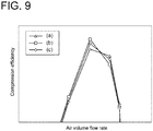
- the compression efficiency by rotation of the impeller 3 i.e., the compression efficiency of the centrifugal compressor 1 may be reduced in the blade (a) as compared with the other two types of blades, depending on the air volume flow rate.
- the compression efficiency of the centrifugal compressor 1 may be maximum in the blade (b) having the curved surface on the pressure surface, depending on the air volume flow rate. This indicates that the compression efficiency of the centrifugal compressor 1 can be improved by further forming the curved surface portion on the pressure surface 20.
- Part (a) of FIG. 10 shows a flow velocity distribution in the vicinity of a boundary layer formed on the suction surface 10 and the pressure surface 20 of the blade, as obtained by CFD analysis on the blade (b) of FIG. 4 .
- Part (b) of FIG. 10 shows a flow velocity distribution in the vicinity of a boundary layer formed on the suction surface 10 and the pressure surface 20 of the blade, as obtained by CFD analysis on the blade (a) of FIG. 4 .
- As shown in part (a) of FIG. 10 when the second curved surface portion 21 is present in the second region R2 of the pressure surface 20 of each blade 4, a boundary layer 40 formed by flow along the pressure surface 20 from the leading edge 4a (see FIG.
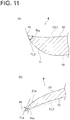
- the first curved surface portion 11 is formed in the first region R1 connected to the trailing edge 4b on the suction surface 10
- the second curved surface portion 21 is formed in the second region R2 connected to the trailing edge 4b on the pressure surface 20
- ⁇ 4b is an angle of a tangent line TL 3 of the first curved surface portion 11 at the trailing edge 4b with respect to the chord line CL2.
- ⁇ 4b is an angle of a tangent line TL 4 of the second curved surface portion 21 at the trailing edge 4b with respect to the chord line CL2.
- the convex curve of the second curved surface portion 21 preferably satisfies ⁇ 4b ⁇ 4b .
- the present inventors confirmed a preferable range of the second region R2 to obtain the convex curve improvement effect by CFD analysis.
- the results are shown in FIG. 12 .
- the graph of FIG. 12 shows a change in flow velocity of the air in the boundary layer (boundary layer flow velocity) with a change in dimensionless height of the second region R2 for the blade (b) of FIG. 4 .
- the graph of FIG. 12 also shows a change in boundary layer flow velocity with a change in dimensionless height of the first region R1 for the blade (a) of FIG. 4 , and a change in boundary layer flow velocity with a change in dimensionless height of the portion 8 having a substantially elliptical cross-section for the blade (c) of FIG. 4 .
- the blade (b) when the dimensionless height of the second region R2 from the tip-side edge 4c is 70% or less, the blade (b) has a higher boundary layer flow velocity than the blades (a) and (c).
- the dimensionless height of the second region R2 from the tip-side edge 4c is 70% or less, preferably 40% or less, more preferably 30% or less, the compression efficiency improvement effect is achieved.
- the trailing edge 4b when the blade 4 is viewed from a direction facing the trailing edge 4b, the trailing edge 4b has a linear shape from the hub-side edge 4d to the tip-side edge 4c.
- the present invention is not limited to this embodiment.
- the trailing edge 4b may be curved from the hub-side edge 4d to the tip-side edge 4c, or for example as shown in part (b) of FIG. 13 , the thickness of the middle portion 30 in the blade height direction may be increased so that the trailing edge 4b have three linear portions.
- FIG. 8 when the trailing edge 4b is linear from the hub-side edge 4d to the tip-side edge 4c, it is possible to improve the manufacturing efficiency of the blade 4.
- the blade 4 is a full blade, the blade is not limited thereto.
- the blade 4 may be a splitter blade disposed between two full blades.
Landscapes
- Engineering & Computer Science (AREA)
- Mechanical Engineering (AREA)
- General Engineering & Computer Science (AREA)
- Structures Of Non-Positive Displacement Pumps (AREA)
- Supercharger (AREA)
Applications Claiming Priority (1)
| Application Number | Priority Date | Filing Date | Title |
|---|---|---|---|
| PCT/JP2018/023830 WO2019244344A1 (fr) | 2018-06-22 | 2018-06-22 | Rotor et machine à compression centrifuge équipée dudit rotor |
Publications (3)
| Publication Number | Publication Date |
|---|---|
| EP3760875A1 true EP3760875A1 (fr) | 2021-01-06 |
| EP3760875A4 EP3760875A4 (fr) | 2021-06-23 |
| EP3760875B1 EP3760875B1 (fr) | 2022-06-15 |
Family
ID=68983623
Family Applications (1)
| Application Number | Title | Priority Date | Filing Date |
|---|---|---|---|
| EP18923649.0A Active EP3760875B1 (fr) | 2018-06-22 | 2018-06-22 | Rotor et machine à compression centrifuge équipée dudit rotor |
Country Status (5)
| Country | Link |
|---|---|
| US (1) | US11408435B2 (fr) |
| EP (1) | EP3760875B1 (fr) |
| JP (1) | JP6998462B2 (fr) |
| CN (1) | CN112041566B (fr) |
| WO (1) | WO2019244344A1 (fr) |
Families Citing this family (1)
| Publication number | Priority date | Publication date | Assignee | Title |
|---|---|---|---|---|
| CN114893441A (zh) * | 2022-04-25 | 2022-08-12 | 珠海格力节能环保制冷技术研究中心有限公司 | 叶片、叶轮及通风设备 |
Family Cites Families (32)
| Publication number | Priority date | Publication date | Assignee | Title |
|---|---|---|---|---|
| US3068801A (en) * | 1958-09-02 | 1962-12-18 | Murray William | Centrifugal impeller pumps |
| US3027845A (en) * | 1959-11-16 | 1962-04-03 | Worthington Corp | Impeller tip pocket |
| US3069072A (en) * | 1960-06-10 | 1962-12-18 | Birmann Rudolph | Impeller blading for centrifugal compressors |
| US3788765A (en) * | 1971-11-18 | 1974-01-29 | Laval Turbine | Low specific speed compressor |
| US4243357A (en) * | 1979-08-06 | 1981-01-06 | Cummins Engine Company, Inc. | Turbomachine |
| US4227855A (en) * | 1978-08-25 | 1980-10-14 | Cummins Engine Company, Inc. | Turbomachine |
| EP0072177B1 (fr) * | 1981-08-07 | 1987-01-07 | Holset Engineering Company Limited | Rotor pour compresseur centrifuge |
| JPS59185898A (ja) * | 1983-04-08 | 1984-10-22 | Aisin Seiki Co Ltd | フアンブレ−ド |
| US6331100B1 (en) * | 1999-12-06 | 2001-12-18 | General Electric Company | Doubled bowed compressor airfoil |
| JP2002021785A (ja) | 2000-07-10 | 2002-01-23 | Mitsubishi Heavy Ind Ltd | 遠心圧縮機 |
| JP3422008B2 (ja) * | 2001-02-19 | 2003-06-30 | 日本サーボ株式会社 | 軸流フアン |
| JP4308718B2 (ja) | 2004-06-15 | 2009-08-05 | 三星電子株式会社 | 遠心ファンおよびこれを用いた空気調和機 |
| US7686567B2 (en) | 2005-12-16 | 2010-03-30 | United Technologies Corporation | Airfoil embodying mixed loading conventions |
| JP2009041373A (ja) | 2007-08-06 | 2009-02-26 | Hitachi Plant Technologies Ltd | ターボ圧縮機 |
| US8308420B2 (en) * | 2007-08-03 | 2012-11-13 | Hitachi Plant Technologies, Ltd. | Centrifugal compressor, impeller and operating method of the same |
| DE102008059874A1 (de) | 2008-12-01 | 2010-06-02 | Continental Automotive Gmbh | Geometrische Gestaltung der Laufradschaufeln eines Turboladers |
| JP5473457B2 (ja) * | 2009-07-29 | 2014-04-16 | 三菱重工業株式会社 | 遠心圧縮機のインペラ |
| FR2969230B1 (fr) | 2010-12-15 | 2014-11-21 | Snecma | Aube de compresseur a loi d'empilage amelioree |
| JP2013015101A (ja) | 2011-07-05 | 2013-01-24 | Ihi Corp | 遠心圧縮機 |
| JP6311855B2 (ja) | 2012-02-29 | 2018-04-18 | 三菱重工業株式会社 | インペラ、及び遠心圧縮機 |
| WO2014050146A1 (fr) * | 2012-09-28 | 2014-04-03 | ダイキン工業株式会社 | Ventilateur hélicoïdal et climatiseur équipé de celui-ci |
| EP3009686B1 (fr) | 2013-06-13 | 2017-11-15 | Mitsubishi Heavy Industries, Ltd. | Hélice et machine à fluide |
| US20150007815A1 (en) * | 2013-06-28 | 2015-01-08 | Carefusion 303, Inc. | Ventilator system |
| US9541098B2 (en) * | 2013-06-28 | 2017-01-10 | Vyaire Medical Capital Llc | Low-noise blower |
| JP5980180B2 (ja) * | 2013-08-08 | 2016-08-31 | 三菱電機株式会社 | 軸流ファン、及び、その軸流ファンを有する空気調和機 |
| EP2987956A1 (fr) * | 2014-08-18 | 2016-02-24 | Siemens Aktiengesellschaft | Aube de compresseur |
| US9765795B2 (en) * | 2014-08-27 | 2017-09-19 | Pratt & Whitney Canada Corp. | Compressor rotor airfoil |
| DE102014219058A1 (de) * | 2014-09-22 | 2016-03-24 | Siemens Aktiengesellschaft | Radialverdichterlaufrad und zugehöriger Radialverdichter |
| JP6607076B2 (ja) * | 2016-02-22 | 2019-11-20 | 株式会社豊田自動織機 | コンプレッサインペラ及びターボチャージャ |
| DE102016107656A1 (de) * | 2016-04-25 | 2017-10-26 | Ebm-Papst Mulfingen Gmbh & Co. Kg | Schaufelkantengeometrie einer Schaufel eines Luftförderrads |
| JP6755331B2 (ja) * | 2016-11-18 | 2020-09-16 | 三菱電機株式会社 | プロペラファン及び冷凍サイクル装置 |
| JP6740271B2 (ja) * | 2018-03-05 | 2020-08-12 | 三菱重工業株式会社 | 羽根車及びこの羽根車を備えた遠心圧縮機 |
-
2018
- 2018-06-22 JP JP2020525201A patent/JP6998462B2/ja active Active
- 2018-06-22 US US17/040,137 patent/US11408435B2/en active Active
- 2018-06-22 WO PCT/JP2018/023830 patent/WO2019244344A1/fr not_active Ceased
- 2018-06-22 EP EP18923649.0A patent/EP3760875B1/fr active Active
- 2018-06-22 CN CN201880092689.1A patent/CN112041566B/zh active Active
Also Published As
| Publication number | Publication date |
|---|---|
| EP3760875B1 (fr) | 2022-06-15 |
| CN112041566A (zh) | 2020-12-04 |
| CN112041566B (zh) | 2022-07-26 |
| WO2019244344A1 (fr) | 2019-12-26 |
| US11408435B2 (en) | 2022-08-09 |
| JPWO2019244344A1 (ja) | 2021-04-30 |
| US20210018014A1 (en) | 2021-01-21 |
| EP3760875A4 (fr) | 2021-06-23 |
| JP6998462B2 (ja) | 2022-01-18 |
Similar Documents
| Publication | Publication Date | Title |
|---|---|---|
| RU2495254C2 (ru) | Лопатка рабочего колеса компрессора с переменным эллиптическим соединением | |
| CN104364473B (zh) | 在根部截面内具有曲面轮廓的飞机涡轮喷气发动机的风扇叶片 | |
| CN101326342B (zh) | 涡轮机叶片 | |
| CN111577655B (zh) | 叶片及使用其的轴流叶轮 | |
| JP2008095695A (ja) | ターボ機械用可動ブレード | |
| EP2613056B1 (fr) | Diffuseur pour compresseur centrifuge et compresseur centrifuge comportant ce diffuseur | |
| CN101166890B (zh) | 涡轮 | |
| CN106121734B (zh) | 一种叶片,包括该叶片的燃气涡轮机,以及制造该叶片的方法 | |
| US11835058B2 (en) | Impeller and centrifugal compressor | |
| EP3760875A1 (fr) | Rotor et machine à compression centrifuge équipée dudit rotor | |
| CN110939603A (zh) | 叶片及使用其的轴流叶轮 | |
| CN108350901B (zh) | 离心压缩机叶轮 | |
| EP3859164A1 (fr) | Aube et turbine à écoulement axial l'utilisant | |
| US11384774B2 (en) | Rotor and centrifugal compressor including the same | |
| KR102556732B1 (ko) | 원심형 압축기 임펠러 및 상기 임펠러를 포함하는 압축기 | |
| US11608835B2 (en) | Blade and axial flow impeller using same | |
| CN213775827U (zh) | 一种轴流压缩机承缸和应用其的轴流压缩机 |
Legal Events
| Date | Code | Title | Description |
|---|---|---|---|
| STAA | Information on the status of an ep patent application or granted ep patent |
Free format text: STATUS: THE INTERNATIONAL PUBLICATION HAS BEEN MADE |
|
| PUAI | Public reference made under article 153(3) epc to a published international application that has entered the european phase |
Free format text: ORIGINAL CODE: 0009012 |
|
| STAA | Information on the status of an ep patent application or granted ep patent |
Free format text: STATUS: REQUEST FOR EXAMINATION WAS MADE |
|
| 17P | Request for examination filed |
Effective date: 20200928 |
|
| AK | Designated contracting states |
Kind code of ref document: A1 Designated state(s): AL AT BE BG CH CY CZ DE DK EE ES FI FR GB GR HR HU IE IS IT LI LT LU LV MC MK MT NL NO PL PT RO RS SE SI SK SM TR |
|
| AX | Request for extension of the european patent |
Extension state: BA ME |
|
| A4 | Supplementary search report drawn up and despatched |
Effective date: 20210521 |
|
| RIC1 | Information provided on ipc code assigned before grant |
Ipc: F04D 29/28 20060101ALI20210517BHEP Ipc: F04D 29/30 20060101AFI20210517BHEP |
|
| DAV | Request for validation of the european patent (deleted) | ||
| DAX | Request for extension of the european patent (deleted) | ||
| GRAP | Despatch of communication of intention to grant a patent |
Free format text: ORIGINAL CODE: EPIDOSNIGR1 |
|
| STAA | Information on the status of an ep patent application or granted ep patent |
Free format text: STATUS: GRANT OF PATENT IS INTENDED |
|
| RIC1 | Information provided on ipc code assigned before grant |
Ipc: F04D 29/28 20060101ALI20211207BHEP Ipc: F04D 29/30 20060101AFI20211207BHEP |
|
| INTG | Intention to grant announced |
Effective date: 20220105 |
|
| GRAJ | Information related to disapproval of communication of intention to grant by the applicant or resumption of examination proceedings by the epo deleted |
Free format text: ORIGINAL CODE: EPIDOSDIGR1 |
|
| STAA | Information on the status of an ep patent application or granted ep patent |
Free format text: STATUS: REQUEST FOR EXAMINATION WAS MADE |
|
| GRAP | Despatch of communication of intention to grant a patent |
Free format text: ORIGINAL CODE: EPIDOSNIGR1 |
|
| STAA | Information on the status of an ep patent application or granted ep patent |
Free format text: STATUS: GRANT OF PATENT IS INTENDED |
|
| INTC | Intention to grant announced (deleted) | ||
| INTG | Intention to grant announced |
Effective date: 20220310 |
|
| GRAS | Grant fee paid |
Free format text: ORIGINAL CODE: EPIDOSNIGR3 |
|
| GRAA | (expected) grant |
Free format text: ORIGINAL CODE: 0009210 |
|
| STAA | Information on the status of an ep patent application or granted ep patent |
Free format text: STATUS: THE PATENT HAS BEEN GRANTED |
|
| AK | Designated contracting states |
Kind code of ref document: B1 Designated state(s): AL AT BE BG CH CY CZ DE DK EE ES FI FR GB GR HR HU IE IS IT LI LT LU LV MC MK MT NL NO PL PT RO RS SE SI SK SM TR |
|
| REG | Reference to a national code |
Ref country code: CH Ref legal event code: EP Ref country code: GB Ref legal event code: FG4D |
|
| REG | Reference to a national code |
Ref country code: IE Ref legal event code: FG4D |
|
| REG | Reference to a national code |
Ref country code: DE Ref legal event code: R096 Ref document number: 602018036908 Country of ref document: DE |
|
| REG | Reference to a national code |
Ref country code: AT Ref legal event code: REF Ref document number: 1498543 Country of ref document: AT Kind code of ref document: T Effective date: 20220715 |
|
| REG | Reference to a national code |
Ref country code: LT Ref legal event code: MG9D |
|
| REG | Reference to a national code |
Ref country code: NL Ref legal event code: MP Effective date: 20220615 |
|
| PG25 | Lapsed in a contracting state [announced via postgrant information from national office to epo] |
Ref country code: SE Free format text: LAPSE BECAUSE OF FAILURE TO SUBMIT A TRANSLATION OF THE DESCRIPTION OR TO PAY THE FEE WITHIN THE PRESCRIBED TIME-LIMIT Effective date: 20220615 Ref country code: NO Free format text: LAPSE BECAUSE OF FAILURE TO SUBMIT A TRANSLATION OF THE DESCRIPTION OR TO PAY THE FEE WITHIN THE PRESCRIBED TIME-LIMIT Effective date: 20220915 Ref country code: LT Free format text: LAPSE BECAUSE OF FAILURE TO SUBMIT A TRANSLATION OF THE DESCRIPTION OR TO PAY THE FEE WITHIN THE PRESCRIBED TIME-LIMIT Effective date: 20220615 Ref country code: HR Free format text: LAPSE BECAUSE OF FAILURE TO SUBMIT A TRANSLATION OF THE DESCRIPTION OR TO PAY THE FEE WITHIN THE PRESCRIBED TIME-LIMIT Effective date: 20220615 Ref country code: GR Free format text: LAPSE BECAUSE OF FAILURE TO SUBMIT A TRANSLATION OF THE DESCRIPTION OR TO PAY THE FEE WITHIN THE PRESCRIBED TIME-LIMIT Effective date: 20220916 Ref country code: FI Free format text: LAPSE BECAUSE OF FAILURE TO SUBMIT A TRANSLATION OF THE DESCRIPTION OR TO PAY THE FEE WITHIN THE PRESCRIBED TIME-LIMIT Effective date: 20220615 Ref country code: BG Free format text: LAPSE BECAUSE OF FAILURE TO SUBMIT A TRANSLATION OF THE DESCRIPTION OR TO PAY THE FEE WITHIN THE PRESCRIBED TIME-LIMIT Effective date: 20220915 |
|
| REG | Reference to a national code |
Ref country code: AT Ref legal event code: MK05 Ref document number: 1498543 Country of ref document: AT Kind code of ref document: T Effective date: 20220615 |
|
| PG25 | Lapsed in a contracting state [announced via postgrant information from national office to epo] |
Ref country code: RS Free format text: LAPSE BECAUSE OF FAILURE TO SUBMIT A TRANSLATION OF THE DESCRIPTION OR TO PAY THE FEE WITHIN THE PRESCRIBED TIME-LIMIT Effective date: 20220615 Ref country code: LV Free format text: LAPSE BECAUSE OF FAILURE TO SUBMIT A TRANSLATION OF THE DESCRIPTION OR TO PAY THE FEE WITHIN THE PRESCRIBED TIME-LIMIT Effective date: 20220615 |
|
| PG25 | Lapsed in a contracting state [announced via postgrant information from national office to epo] |
Ref country code: NL Free format text: LAPSE BECAUSE OF FAILURE TO SUBMIT A TRANSLATION OF THE DESCRIPTION OR TO PAY THE FEE WITHIN THE PRESCRIBED TIME-LIMIT Effective date: 20220615 |
|
| PG25 | Lapsed in a contracting state [announced via postgrant information from national office to epo] |
Ref country code: SM Free format text: LAPSE BECAUSE OF FAILURE TO SUBMIT A TRANSLATION OF THE DESCRIPTION OR TO PAY THE FEE WITHIN THE PRESCRIBED TIME-LIMIT Effective date: 20220615 Ref country code: SK Free format text: LAPSE BECAUSE OF FAILURE TO SUBMIT A TRANSLATION OF THE DESCRIPTION OR TO PAY THE FEE WITHIN THE PRESCRIBED TIME-LIMIT Effective date: 20220615 Ref country code: RO Free format text: LAPSE BECAUSE OF FAILURE TO SUBMIT A TRANSLATION OF THE DESCRIPTION OR TO PAY THE FEE WITHIN THE PRESCRIBED TIME-LIMIT Effective date: 20220615 Ref country code: PT Free format text: LAPSE BECAUSE OF FAILURE TO SUBMIT A TRANSLATION OF THE DESCRIPTION OR TO PAY THE FEE WITHIN THE PRESCRIBED TIME-LIMIT Effective date: 20221017 Ref country code: ES Free format text: LAPSE BECAUSE OF FAILURE TO SUBMIT A TRANSLATION OF THE DESCRIPTION OR TO PAY THE FEE WITHIN THE PRESCRIBED TIME-LIMIT Effective date: 20220615 Ref country code: EE Free format text: LAPSE BECAUSE OF FAILURE TO SUBMIT A TRANSLATION OF THE DESCRIPTION OR TO PAY THE FEE WITHIN THE PRESCRIBED TIME-LIMIT Effective date: 20220615 Ref country code: CZ Free format text: LAPSE BECAUSE OF FAILURE TO SUBMIT A TRANSLATION OF THE DESCRIPTION OR TO PAY THE FEE WITHIN THE PRESCRIBED TIME-LIMIT Effective date: 20220615 Ref country code: AT Free format text: LAPSE BECAUSE OF FAILURE TO SUBMIT A TRANSLATION OF THE DESCRIPTION OR TO PAY THE FEE WITHIN THE PRESCRIBED TIME-LIMIT Effective date: 20220615 |
|
| REG | Reference to a national code |
Ref country code: CH Ref legal event code: PL |
|
| REG | Reference to a national code |
Ref country code: BE Ref legal event code: MM Effective date: 20220630 |
|
| PG25 | Lapsed in a contracting state [announced via postgrant information from national office to epo] |
Ref country code: PL Free format text: LAPSE BECAUSE OF FAILURE TO SUBMIT A TRANSLATION OF THE DESCRIPTION OR TO PAY THE FEE WITHIN THE PRESCRIBED TIME-LIMIT Effective date: 20220615 Ref country code: IS Free format text: LAPSE BECAUSE OF FAILURE TO SUBMIT A TRANSLATION OF THE DESCRIPTION OR TO PAY THE FEE WITHIN THE PRESCRIBED TIME-LIMIT Effective date: 20221015 |
|
| REG | Reference to a national code |
Ref country code: DE Ref legal event code: R097 Ref document number: 602018036908 Country of ref document: DE |
|
| PG25 | Lapsed in a contracting state [announced via postgrant information from national office to epo] |
Ref country code: MC Free format text: LAPSE BECAUSE OF FAILURE TO SUBMIT A TRANSLATION OF THE DESCRIPTION OR TO PAY THE FEE WITHIN THE PRESCRIBED TIME-LIMIT Effective date: 20220615 Ref country code: AL Free format text: LAPSE BECAUSE OF FAILURE TO SUBMIT A TRANSLATION OF THE DESCRIPTION OR TO PAY THE FEE WITHIN THE PRESCRIBED TIME-LIMIT Effective date: 20220615 |
|
| PLBE | No opposition filed within time limit |
Free format text: ORIGINAL CODE: 0009261 |
|
| STAA | Information on the status of an ep patent application or granted ep patent |
Free format text: STATUS: NO OPPOSITION FILED WITHIN TIME LIMIT |
|
| PG25 | Lapsed in a contracting state [announced via postgrant information from national office to epo] |
Ref country code: LU Free format text: LAPSE BECAUSE OF NON-PAYMENT OF DUE FEES Effective date: 20220622 Ref country code: LI Free format text: LAPSE BECAUSE OF NON-PAYMENT OF DUE FEES Effective date: 20220630 Ref country code: IE Free format text: LAPSE BECAUSE OF NON-PAYMENT OF DUE FEES Effective date: 20220622 Ref country code: DK Free format text: LAPSE BECAUSE OF FAILURE TO SUBMIT A TRANSLATION OF THE DESCRIPTION OR TO PAY THE FEE WITHIN THE PRESCRIBED TIME-LIMIT Effective date: 20220615 Ref country code: CH Free format text: LAPSE BECAUSE OF NON-PAYMENT OF DUE FEES Effective date: 20220630 |
|
| 26N | No opposition filed |
Effective date: 20230316 |
|
| GBPC | Gb: european patent ceased through non-payment of renewal fee |
Effective date: 20220915 |
|
| PG25 | Lapsed in a contracting state [announced via postgrant information from national office to epo] |
Ref country code: SI Free format text: LAPSE BECAUSE OF FAILURE TO SUBMIT A TRANSLATION OF THE DESCRIPTION OR TO PAY THE FEE WITHIN THE PRESCRIBED TIME-LIMIT Effective date: 20220615 Ref country code: BE Free format text: LAPSE BECAUSE OF NON-PAYMENT OF DUE FEES Effective date: 20220630 |
|
| PG25 | Lapsed in a contracting state [announced via postgrant information from national office to epo] |
Ref country code: FR Free format text: LAPSE BECAUSE OF NON-PAYMENT OF DUE FEES Effective date: 20220815 |
|
| PG25 | Lapsed in a contracting state [announced via postgrant information from national office to epo] |
Ref country code: GB Free format text: LAPSE BECAUSE OF NON-PAYMENT OF DUE FEES Effective date: 20220915 |
|
| PG25 | Lapsed in a contracting state [announced via postgrant information from national office to epo] |
Ref country code: IT Free format text: LAPSE BECAUSE OF FAILURE TO SUBMIT A TRANSLATION OF THE DESCRIPTION OR TO PAY THE FEE WITHIN THE PRESCRIBED TIME-LIMIT Effective date: 20220615 |
|
| PG25 | Lapsed in a contracting state [announced via postgrant information from national office to epo] |
Ref country code: MK Free format text: LAPSE BECAUSE OF FAILURE TO SUBMIT A TRANSLATION OF THE DESCRIPTION OR TO PAY THE FEE WITHIN THE PRESCRIBED TIME-LIMIT Effective date: 20220615 Ref country code: CY Free format text: LAPSE BECAUSE OF FAILURE TO SUBMIT A TRANSLATION OF THE DESCRIPTION OR TO PAY THE FEE WITHIN THE PRESCRIBED TIME-LIMIT Effective date: 20220615 |
|
| PG25 | Lapsed in a contracting state [announced via postgrant information from national office to epo] |
Ref country code: HU Free format text: LAPSE BECAUSE OF FAILURE TO SUBMIT A TRANSLATION OF THE DESCRIPTION OR TO PAY THE FEE WITHIN THE PRESCRIBED TIME-LIMIT; INVALID AB INITIO Effective date: 20180622 |
|
| PG25 | Lapsed in a contracting state [announced via postgrant information from national office to epo] |
Ref country code: TR Free format text: LAPSE BECAUSE OF FAILURE TO SUBMIT A TRANSLATION OF THE DESCRIPTION OR TO PAY THE FEE WITHIN THE PRESCRIBED TIME-LIMIT Effective date: 20220615 |
|
| PG25 | Lapsed in a contracting state [announced via postgrant information from national office to epo] |
Ref country code: MT Free format text: LAPSE BECAUSE OF FAILURE TO SUBMIT A TRANSLATION OF THE DESCRIPTION OR TO PAY THE FEE WITHIN THE PRESCRIBED TIME-LIMIT Effective date: 20220615 |
|
| PG25 | Lapsed in a contracting state [announced via postgrant information from national office to epo] |
Ref country code: BG Free format text: LAPSE BECAUSE OF FAILURE TO SUBMIT A TRANSLATION OF THE DESCRIPTION OR TO PAY THE FEE WITHIN THE PRESCRIBED TIME-LIMIT Effective date: 20220615 |
|
| PG25 | Lapsed in a contracting state [announced via postgrant information from national office to epo] |
Ref country code: BG Free format text: LAPSE BECAUSE OF FAILURE TO SUBMIT A TRANSLATION OF THE DESCRIPTION OR TO PAY THE FEE WITHIN THE PRESCRIBED TIME-LIMIT Effective date: 20220615 |
|
| PGFP | Annual fee paid to national office [announced via postgrant information from national office to epo] |
Ref country code: DE Payment date: 20250429 Year of fee payment: 8 |