EP3760876A1 - Diffusor für eine strömungsmaschine - Google Patents
Diffusor für eine strömungsmaschine Download PDFInfo
- Publication number
- EP3760876A1 EP3760876A1 EP19184292.1A EP19184292A EP3760876A1 EP 3760876 A1 EP3760876 A1 EP 3760876A1 EP 19184292 A EP19184292 A EP 19184292A EP 3760876 A1 EP3760876 A1 EP 3760876A1
- Authority
- EP
- European Patent Office
- Prior art keywords
- diffuser
- rib
- guide vanes
- arrangement
- rpv
- Prior art date
- Legal status (The legal status is an assumption and is not a legal conclusion. Google has not performed a legal analysis and makes no representation as to the accuracy of the status listed.)
- Withdrawn
Links
Images



Classifications
-
- F—MECHANICAL ENGINEERING; LIGHTING; HEATING; WEAPONS; BLASTING
- F04—POSITIVE - DISPLACEMENT MACHINES FOR LIQUIDS; PUMPS FOR LIQUIDS OR ELASTIC FLUIDS
- F04D—NON-POSITIVE-DISPLACEMENT PUMPS
- F04D29/00—Details, component parts, or accessories
- F04D29/40—Casings; Connections of working fluid
- F04D29/42—Casings; Connections of working fluid for radial or helico-centrifugal pumps
- F04D29/44—Fluid-guiding means, e.g. diffusers
- F04D29/441—Fluid-guiding means, e.g. diffusers especially adapted for elastic fluid pumps
- F04D29/444—Bladed diffusers
-
- F—MECHANICAL ENGINEERING; LIGHTING; HEATING; WEAPONS; BLASTING
- F01—MACHINES OR ENGINES IN GENERAL; ENGINE PLANTS IN GENERAL; STEAM ENGINES
- F01D—NON-POSITIVE DISPLACEMENT MACHINES OR ENGINES, e.g. STEAM TURBINES
- F01D9/00—Stators
- F01D9/02—Nozzles; Nozzle boxes; Stator blades; Guide conduits, e.g. individual nozzles
- F01D9/04—Nozzles; Nozzle boxes; Stator blades; Guide conduits, e.g. individual nozzles forming ring or sector
- F01D9/045—Nozzles; Nozzle boxes; Stator blades; Guide conduits, e.g. individual nozzles forming ring or sector for radial flow machines or engines
-
- F—MECHANICAL ENGINEERING; LIGHTING; HEATING; WEAPONS; BLASTING
- F05—INDEXING SCHEMES RELATING TO ENGINES OR PUMPS IN VARIOUS SUBCLASSES OF CLASSES F01-F04
- F05D—INDEXING SCHEME FOR ASPECTS RELATING TO NON-POSITIVE-DISPLACEMENT MACHINES OR ENGINES, GAS-TURBINES OR JET-PROPULSION PLANTS
- F05D2220/00—Application
- F05D2220/30—Application in turbines
- F05D2220/32—Application in turbines in gas turbines
- F05D2220/321—Application in turbines in gas turbines for a special turbine stage
- F05D2220/3216—Application in turbines in gas turbines for a special turbine stage for a special compressor stage
- F05D2220/3217—Application in turbines in gas turbines for a special turbine stage for a special compressor stage for the first stage of a compressor or a low pressure compressor
-
- F—MECHANICAL ENGINEERING; LIGHTING; HEATING; WEAPONS; BLASTING
- F05—INDEXING SCHEMES RELATING TO ENGINES OR PUMPS IN VARIOUS SUBCLASSES OF CLASSES F01-F04
- F05D—INDEXING SCHEME FOR ASPECTS RELATING TO NON-POSITIVE-DISPLACEMENT MACHINES OR ENGINES, GAS-TURBINES OR JET-PROPULSION PLANTS
- F05D2220/00—Application
- F05D2220/40—Application in turbochargers
-
- F—MECHANICAL ENGINEERING; LIGHTING; HEATING; WEAPONS; BLASTING
- F05—INDEXING SCHEMES RELATING TO ENGINES OR PUMPS IN VARIOUS SUBCLASSES OF CLASSES F01-F04
- F05D—INDEXING SCHEME FOR ASPECTS RELATING TO NON-POSITIVE-DISPLACEMENT MACHINES OR ENGINES, GAS-TURBINES OR JET-PROPULSION PLANTS
- F05D2250/00—Geometry
- F05D2250/50—Inlet or outlet
- F05D2250/52—Outlet
Definitions
- the invention relates to an arrangement with a diffuser for a turbomachine with an impeller upstream of the diffuser, the diffuser and the impeller extending annularly around an axis along a circumferential direction, the ribbed guide vanes extending along the vane height between two diffuser boundary walls starting from a diffuser boundary wall on one Housing side extending in the direction of a diffuser boundary wall on a hub side, the rib guide vanes extending from the housing side along 25% -50% of the diffuser channel width in the direction of the hub side, the rib guide vanes having leading edges which are arranged on a mean rib leading edge diameter, the impeller having impeller blades wherein the impeller blades have rotor trailing edges, the rotor trailing edges being arranged on a mean rotor trailing edge diameter over the respective blade height.
- the invention also relates to a turbomachine with such an arrangement.
- the fluid leaves the impeller radially outwards and from there reaches the diffuser, which typically also has a radial flow from the inside to the outside.
- Diffusers can be bladed or bladed.
- LSD low solidity diffusers
- AE diffuser aerodynamic diffusers
- LSDs offer a significantly better and more extensive driving range than AE diffusers. Almost all bladed diffusers today are LSDs.
- Diffusers for radial machines are already from the EP 2 650 546 A1 known. It is proposed there to arrange the guide vanes of the diffuser in an inclined shape in a standing diffuser arranged behind the impeller (dihedral vanes). With the LSD in particular, this aerodynamic measure is intended to achieve a reduced pressure loss.
- the main task of the invention is to reduce the radial installation space requirement of an LSD so that the otherwise increased radial installation space requirement is no longer so significant compared to an unbladed diffuser.
- radial, axial, tangential or circumferential direction relate to the axis defined at the outset, around which the diffuser extends in an annular manner. In the case of a turbo compressor or a radial turbo compressor, this axis is coaxial with the axis of rotation of the rotor.
- circumferential tangent in the present case also denoted by the reference symbol CDT always means a tangent that touches a circular line around the central axis, the circle radius and the point of contact each clearly arising from the context for the person skilled in the art.
- the invention understands a profile center line to be an imaginary line that extends through the center of a blade profile.
- the blade profile is understood as a two-dimensional shape.
- the profile center line can be constructed in this two-dimensional form, for example by connecting the centers of all inscribed circles by means of a line - the profile center line.
- the diffuser is defined axially by diffuser boundary walls.
- diffuser boundary walls is not to be understood in such a way that the diffuser boundary walls always have an axial surface normal. Rather, this term is intended to mean that the diffuser boundary walls in any case have a radial extent and - even if they have an oblique course with respect to the radial or axial direction - limit the diffuser in the axial direction.
- Another advantageous development of the invention provides that the axial distance between diffuser boundary walls widens in the radial direction.
- turbomachine relates to radial turbomachines which provide a deflection of the process fluid.
- the application for a radial turbo compressor is of primary importance.
- the diffuser is a flow-guiding component of the stator, which is located downstream of the impeller outlet.
- the flow rate of the process fluid is delayed in the diffuser, so that a pressure build-up results in accordance with Bernoulli's principles.
- the diffuser effect results from the radial increase in the cross-sectional area through which the flow passes.
- a change in the diffuser channel width which usually results from the axial extension of the clear width of the diffuser.
- the diffuser can also extend in a manner deviating from the radial direction. Most diffusers, however, extend largely radially.
- the diffuser channel width is limited by the diffuser boundary walls provided on both sides. In the case of a purely radially extending diffuser without axial widening, the diffuser boundary walls also run purely radially.
- the impeller Due to the axial intake of a radial turbo compressor and the radial output of the process fluid from the impeller, in the impeller is deflected from axially to radially.
- the impeller is usually constructed with a wheel disc which connects the impeller to the shaft with a shaft-hub connection.
- the side that does not have the axial suction of the impeller is referred to here as the hub side.
- the other opposite axial side is referred to as the housing side.
- this housing side is also often referred to as the cover disk side.
- the invention understands a blade height as the extension of the blade perpendicular to the main flow direction.
- this flow thread extends essentially perpendicular to the direction of the blade height. If this flow thread extends approximately centrally through the arrangement, it will be approximately 50% of the blade height.
- a rib entry angle REA is defined with respect to the entry edge angle of the diffuser guide vanes and is preferably between 14 ° and 22 °. This geometry effectively takes into account the peculiarities of the ribbed vanes and the flow technology downstream of the impeller.
- the rib angle difference between the rib entry angle and rib exit angle is designed as a metal angle between 4 ° and + 11 °, preferably between 6 ° to 10 °.
- the fin guide vanes have a vane overlap for each position of the vane height, which is defined as the ratio of a chord length of the respective fin guide vane to the circumferential pitch of the arrangement of the fin guide vanes.
- the invention understands the profile chord to be the imaginary connecting line between the leading edge of the profile and the trailing edge or trailing edge.
- the circumferential division - also often referred to simply as a division - is understood to mean the distance in the circumferential direction between the leading edges of the fin guide vanes.
- An advantageous development of the invention in this regard provides that the mean blade overlap (SLD) of the rib guide vanes is between 0.6 ⁇ SLD ⁇ 0.9, preferably between 0.65 ⁇ SLD ⁇ 0.75.
- the impeller has an axial impeller outlet width at the outlet, the diffuser having an axial diffuser duct inlet width at the inlet, an annular space width ratio being defined as the axial diffuser duct inlet width to the axial impeller outlet width, the annular space width ratio ACW preferably 0.8 ⁇ ACW ⁇ 1, particularly preferably between 0.85 ⁇ ACW ⁇ 0.98.
- This ratio leads to surprisingly good aerodynamic results with reduced radial space requirements.
- the diffuser has, downstream of the ribbed guide vanes, diffuser guide vanes which, starting from the housing side, extend along the diffuser channel width to the hub side.
- the diffuser guide vanes are arranged downstream of the rib guide vanes for at least 70% of their chord lengths.
- the ribbed guide vanes also take into account the fact that the process fluid emerging from the impeller has a different flow distribution and speed distribution on the housing side has than on the hub side. To compensate for this difference, the ribbed guide vanes are provided in front of the actual diffuser guide vanes, so that these differences are better compensated and the most homogeneous outflow possible takes place behind the outlet of the diffuser.
- the invention proposes as an advantageous development that the ribbed guide vanes and / or the diffuser guide vanes have a curved and profiled profile.
- Profiled means that the blade profile does not have a constant thickness over the extent in the main flow direction, but is aerodynamically adapted with regard to the profile thickness distribution.
- the blade or the blade profile on the pressure side is designed to be more concave over a wider area than on the suction side - accordingly, the blade profile on the suction side is designed to be convex over a further area of extent.
- an angle of attack is defined as the mathematically positive angle from the circumferential tangent to the tangent at the profile center line.
- a leading edge angle is an angle of attack at the leading edge and an exit edge angle is an angle of attack at the trailing edge of the diffuser guide vane.
- leading edge angle is between 23 ° ⁇ LEA ⁇ 30 ° ..
- leading edge angle For the difference between the leading edge angle and the trailing edge angle averaged over the blade height, the following preferably applies: -4> leading edge angle - trailing edge angle> 10 °.
- a negative difference between the leading edge angle and the exit angle or the rib entry angle and the rib exit angle indicates that the blade tapers more tangentially than the inlet is designed.
- a flow fluid that would at least largely or completely follow such a blade design has a more tangential flow orientation after flowing through such a blade arrangement with such a negative difference.
- ratio of the number of rib guide vanes to the number of diffuser guide vanes is 0.5, 1 or 2. It is useful if the arrangement has 8-24 diffuser guide vanes.
- the diffuser in the area of the inlet edges of the diffuser guide vanes the diffuser has an axial diffuser guide vane inlet width, with the diffuser having an axial diffuser guide vane outlet width in the area of the outlet edges of the diffuser guide vanes, a guide vane inlet guide vane outlet width being defined as the axial diffuser guide vane width ratio to the diffuser guide vane outlet width 1 , 0 ⁇ AVW ⁇ 1 , 4th
- the diffuser boundary wall on the hub side extends less obliquely to the radial direction than the diffuser boundary wall on the housing side, such that at least 80% of the axial expansion results from the inclination of the diffuser boundary wall on the housing side.
- the invention also relates to a turbomachine with an arrangement of the type defined above.
- Figure 1 shows a fluid flow machine CMP with an arrangement ARA with a diffuser DFF and an impeller IMP arranged upstream of the diffuser DFF.
- the impeller IMP and the diffuser DFF extend annularly along a circumferential direction CDR of an axis X with an axis of rotation ROT.
- the impeller IMP is fastened in a specific axial position to a shaft SHT which is rotatably mounted about the axis of rotation ROT or the axis X arranged coaxially to the axis of rotation ROT.
- the impeller IMP has a wheel disc HUB, impeller blades BLD and a cover plate SHR, the impeller blades BLD being attached between the wheel disc HUB and the cover plate SHR, forming flow channels.
- a process fluid PFL is sucked in axially and deflected outward in the radial direction, where it exits the rotating impeller IMP during operation and enters a static diffuser DFF.
- Ribbed guide vanes RPV of the static diffuser DFF homogenize and correct the speed distribution of the exiting process fluid PFL before it is introduced into a spiral VLT.
- the rib guide vanes RPV extend along the vane height AFH between two diffuser boundary walls LDW starting from a diffuser boundary wall LDW on a housing side CSS in the direction of a diffuser boundary wall LDW on a hub side HBS.
- the impeller IMP has an axial impeller outlet width AXW at the outlet, the diffuser DFF having an axial diffuser channel inlet width IDW at the inlet, an annular space width ratio ACW being defined as the axial diffuser channel inlet width IDW to the axial impeller outlet width (AXW): 0.8 ⁇ ACW ⁇ 1, the following applies particularly preferably: 0 , 85 ⁇ ACW ⁇ 0 , 98
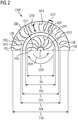
- FIG Figure 2 shows a section according to II-II of FIG Figure 1 schematic.
- the impeller IMP is shown rotatable about the X axis.
- the impeller blades BLD of the impeller IMP are shown schematically with a concave pressure side PRS and a convex suction side SCS - as are the ribbed guide vanes RPV.
- the rotor trailing edges RRE of the impeller blades BLD are set back somewhat compared to the maximum diameter IPD of the impeller IMP on a rotor trailing edge diameter TRI. Downstream there are leading edges LEE of the fin guide vanes RPV on a leading edge diameter DLE.
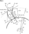
- Figure 3 shows a detail that is in the Figure 2 is shown with III.
- the ones in the Figure 3 The illustrated relationships relate to angular relationships on ribbed guide vanes RPV and also to diffuser guide vanes VNS, which with the respective blade height AFH not only extend over part of the diffuser channel width ADW, but over the entire axial distance of the diffuser boundary walls LDW.
- the relationships shown in this presentation apply mutatis mutandis to diffuser guide vanes VNS or ribbed guide vanes RPV, so that in FIG Figure 3 partly also identical reference symbols - which indicate an identical component meaning - and relationships are reproduced for both arrangements.
- the two in Figure 3 illustrated exemplary ribbed guide vanes RPV or diffuser guide vanes VNS (hereinafter referred to as Figure 3 only referred to as diffuser guide vanes VNS) have for each position of the vane height AFH in their arrangement to each other a vane overlap SLD, which is defined as the ratio of a chord length CHD of the respective diffuser vane VNS to the circumferential pitch CCP of the arrangement of the ribbed vanes RPV or diffuser vanes VNS.
- the mean blade overlap SLD of the ribbed guide vanes RPV is between 0.6 ⁇ SLD ⁇ 0.9, particularly preferably 0.65 ⁇ SLD ⁇ 0.75.
- an angle of attack PMA is defined as the mathematically positive angle from the circumferential rod CDT to the tangent PMT at the profile center line SCL of the profile.
- a leading edge angle LEA or rib entry angle REA is an angle of attack PMA at the leading edge LEE of a diffuser guide vane VNS or rib guide vane RPV.
- An exit edge angle EXA is an angle of attack PMA at an exit edge TRE of the diffuser guide vanes VNS.
- a rib entry angle REA is a rib angle of attack RMA at an entry edge LEE of a rib guide vane RPV, where the following applies to the mean rib entry angle REA: 12 ° ⁇ REA ⁇ 20th ° .
- the rib guide vanes RPV 4th ° ⁇ REA - RXA ⁇ 11 ° , prefers 6th ° ⁇ REA - RX ⁇ 10 ° .
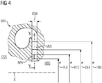
- FIG. 4 and 5 also the Figure 6 show different views of an embodiment with diffuser guide vanes VNS arranged downstream of the ribbed guide vanes RPV, which, starting from the housing side CSS, extend along the entire diffuser channel width ADW in the direction of the hub side HBS.
- the leading edge angle LEA of the diffuser guide vanes VNS is between 23 ° ⁇ LEA ⁇ 30 °, whereby the following preferably applies for a difference leading edge angle (LEA) - exit edge angle (EXA) for the diffuser guide vanes VNS: - 4th ° ⁇ LEA - EXA ⁇ 10 ° .
- a diffuser guide vane VNS is arranged upstream of the rib guide vane RPV, the following preferably applies: 12 ° > REA > 20th ° .
- the ratio of the number of rib guide vanes RPV to the number of diffuser guide vanes VNS is particularly expediently: 0.5 or 1 or 2.
- the arrangement ARA has 8-24 diffuser guide vanes VNS particularly expediently.
- a blade overlap SLD between 0.45 and 0.9, particularly preferably between 0.65 and 0.75, applies.
- the blade overlap SLD is defined here as the ratio of a profile chord length CHD of the respective diffuser blade VNS to the circumferential pitch CCP of the arrangement of the diffuser blades VNS.
- Figure 6 shows the combination of the axial expansion of the diffuser channel width or the inclined housing-side diffuser boundary wall LDW with the arrangement of the ribbed guide vanes RPV upstream of the diffuser guide vanes VNS. Furthermore shows Figure 6 an expansion of the axial distance between the axial diffuser boundary walls LDW with increasing radial extent.
- the diffuser boundary walls LDW are designed in such a way that the diffuser boundary wall LDW extends less obliquely to the radial direction on the hub side HUB than the diffuser boundary wall LDW on the housing side SHR. This results in an axial expansion of at least 80% exclusively from the inclination of the diffuser boundary wall LDW on the CSS side of the housing.
- the diffuser DFF in the area of the inlet edges LEE of the diffuser guide vanes VNS the diffuser DFF has an axial diffuser guide vane inlet width IVW, wherein in the area of the outlet edges of the diffuser guide vanes VNS the diffuser DFF has an axial diffuser guide vane outlet width AVW defined as a diffuser guide vane outlet width AVW axial diffuser guide vane outlet width EVW for axial diffuser guide vane inlet width IVW 1 , 0 ⁇ AVW ⁇ 1 , 4th
- the leading edges LEE of the diffuser guide vanes VNS outside a surrounding area of +/- 10% of the pitch CCP of the ribbed guide vanes RPV in the circumferential direction CDR starting from a Tangent to the profile center line RHD of the rib guide vane RPV at the trailing edge TRE of the rib guide vanes RPV arranged upstream of the diffuser guide vanes VNS.
- the number of diffuser guide vanes VNS is twice as high as that of the ribbed guide vane RPV and the diffuser guide vanes VNS are particularly preferably located, starting from a tangent to the profile center line RHD of the ribbed guide vane RPV, on the trailing edge TRE of the ribs VNS arranged upstream of the diffuser guide vanes RPV Ribbed vanes RPV.
Landscapes
- Engineering & Computer Science (AREA)
- Mechanical Engineering (AREA)
- General Engineering & Computer Science (AREA)
- Structures Of Non-Positive Displacement Pumps (AREA)
Abstract
Die Erfindung betrifft eine Anordnung (ARA) mit einem Diffusor (DFF) für eine Strömungsmaschine (CMP) mit einem Laufrad (IMP) stromaufwärts des Diffusors (DFF), wobei der Diffusor (DFF) und das Laufrad (IMP) sich ringförmig um eine Achse (X) entlang einer Umfangsrichtung (CDR) erstrecken, wobei sich die Rippenleitschaufeln (RPV) ausgehend von der Gehäuseseite (CSS) entlang 25%-50% der Diffusorkanalbreite (ADW) in Richtung der Nabenseite (HBS) erstrecken und Eintrittskanten (LEE) aufweisen, die an einem mittleren Rippeneintrittskantendurchmesser (RLE) angeordnet sind, wobei das Laufrad (IMP) Laufradschaufeln (BLD) aufweist, wobei die Laufradschaufeln (BLD) Rotoraustrittskanten (TRE) aufweisen, wobei die Rotoraustrittskanten (TRE) im Mittel über die jeweilige Schaufelhöhe (AFH) an einem mittleren Rotoraustrittskantendurchmesser (TRI) angeordnet sind. Zur Verbesserung der aerodynamischen Wirkung des Diffusors wird vorgeschlagen, dass für das Verhältnis (RDT) eines Rippeneintrittskantendurchmessers zu einem mittleren Rotoraustrittskantendurchmesser gilt: 1.04 < RLE/TRI < 1.1. So kann gleichzeitig der notwendige Bauraum reduziert werden.
Description
- Die Erfindung betrifft eine Anordnung mit einem Diffusor für eine Strömungsmaschine mit einem Laufrad stromaufwärts des Diffusors, wobei der Diffusor und das Laufrad sich ringförmig um eine Achse entlang einer Umfangsrichtung erstrecken, wobei sich die Rippenleitschaufeln entlang der Schaufelhöhe zwischen zwei Diffusorbegrenzungswänden ausgehend von einer Diffusorbegrenzungswand an einer Gehäuseseite in Richtung einer Diffusorbegrenzungswand an einer Nabenseite erstrecken, wobei die Rippenleitschaufeln ausgehend von der Gehäuseseite entlang 25%-50% der Diffusorkanalbreite in Richtung der Nabenseite erstrecken, wobei die Rippenleitschaufeln Eintrittskanten aufweisen, die an einem mittleren Rippeneintrittskantendurchmesser angeordnet sind, wobei das Laufrad Laufradschaufeln aufweist, wobei die Laufradschaufeln Rotoraustrittskanten aufweisen, wobei die Rotoraustrittskanten im Mittel über die jeweilige Schaufelhöhe an einem mittleren Rotoraustrittskantendurchmesser angeordnet sind. Weiterhin betrifft die Erfindung eine Strömungsmaschine mit einer solchen Anordnung.
- Bei Radialverdichtern verlässt das Fluid das Laufrad nach radial außen und gelangt von dort in den Diffusor, welcher typischerweise ebenfalls radial von innen nach außen durchströmt wird. Diffusoren können beschaufelt oder unbeschaufelt ausgeführt sein. Bei den beschaufelten Arten wird zwischen Low-Solidity-Diffusoren [LSD] mit geringer Schaufelüberdeckung (mit Leitschaufeln, die einen verhältnismäßig großen Abstand zueinander in Umfangsrichtung im Verhältnis zu deren Radialerstreckung aufweisen) und Kanaldiffusoren - auch als aerodynamische Diffusoren [AE-Diffusor] bezeichnet - unterschieden. Aufgrund der Nachteile bzgl. des Fahrbereichs werden AE-Diffusoren sehr selten eingesetzt. LSDs bieten dagegen einen deutlich besseren also umfangreicheren Fahrbereich als AE-Diffusoren. Heutzutage sind nahezu alle beschaufelten Diffusoren LSDs.
- LSDs werden aus den folgenden Gründen eingesetzt:
- Unterdrücken von Rotating Stall, welcher im Falle eines unbeschaufelten Ringraums ggf. auftreten könnte
- Steigerung des Wirkungsgrades der Stufe durch Aufrichten der Strömung und durch Vergleichmäßigung der Strömung über der Kanalhöhe. Dies führt zu einer Reduktion von Verlusten in den nachgeschalteten Komponenten wie Rückführstufe oder Spirale.
- Besserer Kennlinienanstieg zur Pumpgrenze.
- Nachteile von LSDs sind:
- Reduzierter Fahrbereich (schmalere Kennlinie) im Vergleich zur unbeschaufelten Variante
- Höherer Lärmpegel
- Höhere Laufradanregung
- Notwendige radiale Erstreckung des Diffusors größer als für den unbeschaufelten Diffusor
- Notwendige Sammelspiralgehäusegröße nimmt mit LSD zu, da die Umfangskomponente der Geschwindigkeit (Transportgröße in der Spirale) durch den LSD reduziert wird.
- Diffusoren für Radialmaschinen sind bereits aus der
EP 2 650 546 A1 bekannt. Dort wird vorgeschlagen, die Leitschaufeln des Diffusors in geneigter Form in einem hinter dem Laufrad angeordneten stehenden Diffusor anzuordnen (dihedral vanes). Insbesondere beim LSD soll mittels dieser aerodynamischen Maßnahme ein verringerter Druckverlust erzielt werden. - Aus den
WO2019057412A1 ,WO2019057413A1 ,WO2019057414A1 sind bereits Anordnungen aus Laufrädern und Diffusoren von insbesondere Turboverdichtern bekannt. - Aus der
US4850795A und derEP446900B1 - Ausgehend insbesondere von den beschriebenen Nachteilen hat es sich die Erfindung vorrangig zur Aufgabe gemacht, radialen Bauraumbedarf eines LSD's zu verringern, so dass der ansonsten vergrößerte radiale Bauraumbedarf gegenüber einem unbeschaufelten Diffusor nicht mehr so stark ins Gewicht fällt.
- Zur Lösung des Problems wird ein Diffusor bzw. eine Anordnung und eine Strömungsmaschine mit einem solchen Diffusor mit den eingangs definierten Merkmalen vorgeschlagen, der die zusätzlichen Merkmale des Kennzeichens des Anspruchs 1 aufweist. Die rückbezogenen Unteransprüchen beinhalten vorteilhafte Weiterbildungen der Erfindung.
- Begriffe, wie radial, axial, tangential oder Umfangsrichtung beziehen sich auf die eingangs definierte Achse, um die sich der Diffusor ringförmig erstreckt. Diese Achse ist im Falle eines Turboverdichters bzw. eines Radialturboverdichters koaxial zu der Drehachse des Rotors.
- Sämtliche Winkelangaben beziehen sich hierbei stets auf die gegenständlichen Winkel an den tatsächlichen geometrischen Formen - kurz: Metallwinkel.
- Der Begriff Umfangstangente (vorliegend auch mit dem Bezugszeichen CDT bezeichnet) bedeutet vorliegend immer eine Tangente, die eine Kreislinie um die zentrale Achse berührt, wobei sich der Kreisradius und der Berührpunkt jeweils eindeutig für den Fachmann aus dem Zusammenhang ergeben.
- Unter einer Profilmittellinie versteht die Erfindung eine gedachte Linie, die sich durch die Mitte eines Schaufelprofiles erstreckt. Hierbei wird das Schaufelprofil als eine zweidimensionale Form aufgefasst. Die Profilmittellinie kann in dieser zweidimensionalen Form konstruiert werden, indem beispielsweise die Mittelpunkte aller eingeschriebenen Kreise mittels einer Linie - der Profilmittellinie - verbunden werden.
- Der Diffusor wird axial von Diffusorbegrenzungswänden definiert. Hierbei ist der Begriff "Diffusorbegrenzungswände" nicht derart zu verstehen, dass die Diffusorbegrenzungswände immer eine axiale Flächennormale aufweisen. Vielmehr soll dieser Begriff bedeuten, dass die Diffusorbegrenzungswände jedenfalls eine Radialerstreckung aufweisen und - auch wenn sie einen gegenüber der Radialen oder Axialen schrägem Verlauf aufweisen - den Diffusor in Axialrichtung begrenzen. Eine weitere vorteilhafte Weiterbildung der Erfindung sieht vor, dass sich in radialer Richtung der Axialabstand zwischen Diffusorbegrenzungswänden aufweitet.
- Der Begriff Strömungsmaschine bezieht sich nach der Erfindung auf radiale Turbomaschinen, die eine Umlenkung des Prozessfluids vorsehen. Von vorrangiger Bedeutung ist hierbei die Anwendung für einen Radialturboverdichter. Insbesondere im Falle des Radialturboverdichters ist der Diffusor ein strömungsleitendes Bauteil des Stators, das sich stromabwärts des Laufradaustritts befindet. In dem Diffusor wird in der Regel die Strömungsgeschwindigkeit des Prozessfluids verzögert, so dass sich gemäß der Gesetzmäßigkeiten von Bernoulli ein Druckaufbau ergibt.
- Im Falle des Radialturboverdichters und eines sich im Wesentlichen radial nach außen erstreckenden Diffusors ergibt sich die Diffusor-Wirkung schon allein durch die radiale Zunahme der durchströmten Querschnittsfläche. Zusätzlich von Bedeutung ist eine Veränderung der Diffusorkanalbreite, die sich im Regelfall als die axiale Erstreckung der lichten Weite des Diffusors ergibt. Grundsätzlich kann sich der Diffusor auch abweichend von der Radialrichtung erstrecken. Die meisten Diffusoren erstrecken sich aber weitestgehend radial. Die Diffusorkanalbreite wird begrenzt durch an beiden Seiten vorgesehenen Diffusorbegrenzungswänden. Im Falle eines sich rein radial erstreckenden Diffusors ohne axiale Aufweitung laufen die Diffusorbegrenzungswände ebenfalls rein radial. Aufgrund der axialen Ansaugung eines Radialturboverdichters und der radialen Ausgabe des Prozessfluids aus dem Laufrad findet in dem Laufrad eine Umlenkung von axial nach radial statt. Das Laufrad ist hierbei in der Regel mit einer Radscheibe aufgebaut, die mit einer Welle-Nabe-Verbindung das Laufrad mit der Welle verbindet. Diejenige Seite, die nicht die axiale Ansaugung des Laufrades aufweist, wird hierbei als die Nabenseite bezeichnet. Die andere gegenüberliegende Axialseite wird als Gehäuseseite bezeichnet. Bei Laufrädern, die gehäuseseitig eine Deckscheibe aufweisen, wird diese Gehäuseseite auch häufig als die Deckscheibenseite bezeichnet. Unter einer Schaufelhöhe versteht die Erfindung die Erstreckung der Schaufel senkrecht zur Hauptströmungsrichtung. Folgt man einem - für die Hauptströmungsrichtung - repräsentativen Strömungsfaden durch die Anordnung der Erfindung, beispielsweise durch den Diffusor, so erstreckt sich dieser Strömungsfaden im Wesentlichen senkrecht zur Richtung der Schaufelhöhe. Erstreckt sich dieser Strömungsfaden in etwa mittig durch die Anordnung wird er in etwa bei 50% der Schaufelhöhe liegen.
- Das erfindungsgemäße Merkmal, dass für das Verhältnis RDT eines Rippeneintrittskantendurchmessers zu einem mittleren Rotoraustrittskantendurchmesser gilt:
1,04 < Verhältnis RDT < 1,1 führt zu einer besonders effektiven und raumsparenden Berücksichtigung des Unterschiedes zwischen der Gehäuseseite und der Nabenseite. - Für die Rippenleitschaufeln ist ein Rippeneintrittswinkel REA definiert zu dem Eintrittskantenwinkel der Diffusorleitschaufeln und beträgt bevorzugt zwischen 14° und 22°. Diese Geometrie berücksichtigt effektiv die Besonderheiten der Rippenleitschaufeln und der Strömungstechnik stromabwärts des Laufrades.
- Bei einer analogen Definition des Rippenaustrittswinkels zu sieht eine weitere vorteilhafte Weiterbildung vor, dass gemittelt über die Schaufelhöhe die Rippenanstellwinkeldifferenz zwischen Rippeneintrittswinkel und Rippenaustrittswinkel zwischen 4° und +11°, bevorzugt zwischen 6° bis 10° als Metallwinkel ausgelegt ist.
- Hierbei weisen die Rippenleitschaufeln für jede Position der Schaufelhöhe eine Schaufelüberdeckung auf, die definiert ist als das Verhältnis einer Profilsehnenlänge der jeweiligen Rippenleitschaufel zur Umfangsteilung der Anordnung der Rippenleitschaufeln. Unter der Profilsehne versteht die Erfindung die gedachte Verbindungslinie zwischen der Eintrittskante des Profils und der Austrittskante bzw. Hinterkante. Unter der Umfangsteilung - auch häufig einfach als Teilung bezeichnet - versteht man den Abstand in Umfangsrichtung zwischen den Vorderkanten der Rippenleitschaufeln. Eine diesbezügliche vorteilhafte Weiterbildung der Erfindung sieht vor, dass die mittlere Schaufelüberdeckung (SLD) der Rippenleitschaufeln zwischen 0,6 < SLD < 0,9, bevorzugt zwischen 0,65 < SLD < 0,75 beträgt.
- Eine vorteilhafte Weiterbildung der Erfindung sieht vor, dass das Laufrad am Austritt eine axiale Laufradaustrittsbreite aufweist, wobei der Diffusor am Eintritt eine axiale Diffusorkanaleintrittsbreite aufweist, wobei ein Ringraumbreitenverhältnis definiert ist als axiale Diffusorkanaleintrittsbreite zu axialer Laufradaustrittsbreite wobei das Ringraumbreitenverhältnis ACW bevorzugt 0,8 < ACW <1 beträgt, besonders bevorzugt zwischen 0,85 < ACW <0,98 beträgt. Dieses Verhältnis führt zu überraschend guten aerodynamischen Ergebnissen bei verringertem Radialraumbedarf.
- Eine andere vorteilhafte Weiterbildung der Erfindung sieht vor, dass der Diffusor stromabwärts der Rippenleitschaufeln Diffusorleitschaufeln aufweist, die sich ausgehend von der Gehäuseseite entlang der Diffusorkanalbreite bis zu der Nabenseite erstrecken. Die Diffusorleitschaufeln sind hierbei zu mindestens 70% ihrer Profilsehnenlängen stromabwärts der Rippenleitschaufeln angeordnet.
- Die Rippenleitschaufeln tragen dem Umstand zusätzlich Rechnung, dass das aus dem Laufrad austretende Prozessfluid auf der Gehäuseseite eine andere Strömungsverteilung und Geschwindigkeitsverteilung hat als auf der Nabenseite. Zum Ausgleich dieser Differenz sind die Rippenleitschaufeln vor den eigentlichen Diffusorleitschaufeln vorgesehen, so dass diese Unterschiede besser ausgeglichen werden und hinter dem Austritt des Diffusors eine möglichst homogene Abströmung erfolgt.
- Weiterhin schlägt die Erfindung als vorteilhafte Weiterbildung vor, dass die Rippenleitschaufeln und/oder die Diffusorleitschaufeln ein gewölbtes und profiliertes Profil aufweisen. Profiliert bedeutet hierbei, dass das Schaufelprofil keine konstante Dicke über die Erstreckung in Hauptströmungsrichtung aufweist, sondern aerodynamisch hinsichtlich der Profildickenverteilung angepasst ist.
- In der Regel ist die Schaufel bzw. das Schaufelprofil auf der Druckseite über einen weiteren Erstreckungsbereich konkaver gestaltet als auf der Saugseite - dementsprechend ist das Schaufelprofil auf der Saugseite über einen weiteren Erstreckungsbereich konvex gestaltet.
- Eine andere vorteilhafte Weiterbildung der Erfindung sieht vor, dass für jede Position entlang der Profilmittellinie des Schaufelprofils der Diffusorleitschaufeln ein Anstellwinkel definiert ist als der mathematisch positive Winkel von der Umfangstangente auf die Tangente an der Profilmittellinie. Hierbei ist jeweils ein Eintrittskantenwinkel ein Anstellwinkel an der Eintrittskante und ein Austrittskantenwinkel ein Anstellwinkel an der Austrittskante der Diffusorleitschaufel.
- Bevorzugt beträgt der wobei der Eintrittskantenwinkel zwischen 23° < LEA < 30°..
- Für die Differenz zwischen Eintrittskantenwinkel und Austrittskantenwinkel gemittelt über die Schaufelhöhe gilt bevorzugt: -4 > Eintrittskantenwinkel - Austrittskantenwinkel > 10°.
- Eine negative Differenz zwischen dem Eintrittskantenwinkel und dem Austrittswinkel bzw. dem Rippeneintrittswinkel und dem Rippenaustrittswinkel (Rippenanstellwinkeldifferenz RFA) zeigt an, dass die Schaufel tangentialer ausläuft als der Eintritt gestaltet ist. Ein Strömungsfluid, dass einer derartigen Schaufelgestaltung zumindest weitestgehend oder vollkommen folgen würde, hat bei einer derartigen negativen Differenz eine tangentialere Strömungsausrichtung nach Durchströmung einer derartigen Schaufelanordnung.
- Eine vorteilhafte Weiterbildung sieht vor, dass das Verhältnis der Anzahl der Rippenleitschaufeln zu der Anzahl der Diffusorleitschaufeln 0,5, 1 oder 2 ist. Hierbei ist es zweckmäßig, wenn die Anordnung 8-24 Diffusorleitschaufeln aufweist.
- Eine andere vorteilhafte Weiterbildung sieht vor, dass im Bereich von Eintrittskanten der Diffusorleitschaufeln der Diffusor eine axiale Diffusorleitschaufeleintrittsbreite aufweist, wobei im Bereich von Austrittskanten der Diffusorleitschaufeln der Diffusor eine axiale Diffusorleitschaufelaustrittsbreite aufweist, wobei ein Leitschaufelringraumbreitenverhältnis AVW definiert ist als axiale Diffusorleitschaufelaustrittsbreite zur axialen Diffusorleitschaufeleintrittsbreite

- Eine vorteilhafte Weiterbildung dieses Merkmals sieht vor, dass die Diffusorbegrenzungswand auf der Nabenseite sich weniger schräg zur Radialrichtung erstreckt als die Diffusorbegrenzungswand auf der Gehäuseseite, derart, dass mindestens 80% der axialen Aufweitung sich aus der Schrägstellung der Diffusorbegrenzungswand auf der Gehäuseseite ergibt.
- Weiterhin betrifft die Erfindung eine Strömungsmaschine mit einer Anordnung der vorab definierten Art.
- Im Folgenden ist die Erfindung anhand verschiedener Figuren zum besseren Verständnis unter Darstellung bevorzugter Ausführungsbeispiele illustriert. Es zeigen:
- Figur 1
- einen schematischen Längsschnitt entlang einer Drehachse durch eine erfindungsgemäße Strömungsmaschine mit einem erfindungsgemäßen Diffusor bzw. einer erfindungsgemäßen Anordnung,
- Figur 2
- einen Schnitt II-II entlang einer Hauptströmungsrichtung gemäß
Figur 1 , - Figur 3
- das Detail III aus
Figur 2 , - Figur 4
- eine schematische Darstellung eines Längsschnitts durch eine Strömungsmaschine beschränkt auf das Detail des Diffusors,
- Figur 5
- den Schnitt V-V aus
Figur 4 , - Figur 6
- eine schematische Darstellung eines Längsschnitts durch einen Diffusor mit aufgeweiteter Diffusorkanalbreite mit Rippenleitschaufeln.
- In den Figuren bedeuten gleiche Bezugszeichen funktionsgleiche Bauteile.
-
Figur 1 zeigt eine Strömungsmaschine CMP mit einer Anordnung ARA mit einem Diffusor DFF und einem stromaufwärts des Diffusors DFF angeordneten Laufrad IMP. Das Laufrad IMP und der Diffusors DFF erstrecken sich ringförmig entlang einer Umfangsrichtung CDR einer Achse X mit einer Drehachse ROT. Das Laufrad IMP ist einer bestimmten Axialposition an einer um die Drehachse ROT bzw. die koaxial zur Drehachse ROT angeordnete Achse X drehbar gelagerte Welle SHT befestigt. Das Laufrad IMP weist eine Radscheibe HUB, Laufradschaufeln BLD und eine Deckscheibe SHR auf, wobei die Laufradschaufeln BLD Strömungskanäle ausbildend sich befestigt zwischen der Radscheibe HUB und der Deckscheibe SHR befinden. Ein Prozessfluid PFL wird axial angesaugt und in die Radialrichtung nach außen umgelenkt, wo es aus dem rotierenden Laufrad IMP im Betrieb austretend in einen statischen Diffusor DFF gelangt. - Rippenleitschaufeln RPV des statischen Diffusors DFF homogenisieren und korrigieren die Geschwindigkeitsverteilung des austretenden Prozessfluids PFL bevor es in eine Spirale VLT eingeleitet wird. Die Rippenleitschaufeln RPV erstrecken sich entlang der Schaufelhöhe AFH zwischen zwei Diffusorbegrenzungswänden LDW ausgehend von einer Diffusorbegrenzungswand LDW an einer Gehäuseseite CSS in Richtung einer Diffusorbegrenzungswand LDW an einer Nabenseite HBS.
- Eine vorteilhafte Weiterbildung der Erfindung sieht vor, dass das Laufrad IMP am Austritt eine axiale Laufradaustrittsbreite AXW aufweist, wobei der Diffusor DFF am Eintritt eine axiale Diffusorkanaleintrittsbreite IDW aufweist, wobei ein Ringraumbreitenverhältnis ACW definiert ist als axiale Diffusorkanaleintrittsbreite IDW zu axialer Laufradaustrittsbreite (AXW) mit:
0,8 < ACW <1, besonders bevorzugt gilt:
-
Figur 2 zeigt einen Schnitt gemäß II-II derFigur 1 schematisch. Entgegen der dort illustrierten Umfangsrichtung CDR, in einer Rotationsrichtung RDR ist dort das Laufrad IMP rotierbar um die Achse X dargestellt. Schematisch sind die Laufradschaufeln BLD des Laufrades IMP gezeigt mit einer konkaven Druckseite PRS und einer konvexen Saugseite SCS - ebenso die Rippenleitschaufeln RPV. Die Rotoraustrittskanten RRE der Laufradschaufeln BLD sind gegenüber dem Maximaldurchmesser IPD des Laufrads IMP etwas zurückversetzt auf einem Rotoraustrittskantendurchmesser TRI. Stromabwärts befinden sich Eintrittskanten LEE der Rippenleitschaufeln RPV auf einem Eintrittskantendurchmesser DLE. - Erfindungsgemäß gilt für das Verhältnis RDT des Rippeneintrittskantendurchmessers RLE zu dem mittleren Rotoraustrittskantendurchmesser TRI gilt: 1,04 < RLE/TRI < 1,1.
-
Figur 3 zeigt ein Detail, das in derFigur 2 mit III ausgewiesen ist. Die in derFigur 3 illustrierten Zusammenhänge beziehen sich auf Winkelverhältnisse an Rippenleitschaufeln RPV und ebenso auf Diffusorleitschaufeln VNS, die sich mit der jeweiligen Schaufelhöhe AFH nicht nur über einen Teil der Diffusorkanalbreite ADW erstrecken, sondern über den gesamten Axialabstand der Diffusorbegrenzungswände LDW. Die in dieser Darlegung aufgezeigten Zusammenhänge sind für Diffusorleitschaufeln VNS bzw. Rippenleitschaufeln RPV mutatis mutandis gültig, so dass in derFigur 3 teils auch identische Bezugszeichen - die eine identische Bauteilbedeutung ausweisen - und Zusammenhänge für beide Anordnungen wiedergegeben sind. - Die beiden in
Figur 3 abgebildeten exemplarischen Rippenleitschaufeln RPV bzw. Diffusorleitschaufeln VNS (nachfolgend fürFigur 3 nur als Diffusorleitschaufeln VNS bezeichnet) weisen für jede Position der Schaufelhöhe AFH in ihrer Anordnung zueinander eine Schaufelüberdeckung SLD auf, die definiert ist als das Verhältnis einer Profilsehnenlänge CHD der jeweiligen Diffusorleitschaufel VNS zur Umfangsteilung CCP der Anordnung der Rippenleitschaufeln RPV bzw. Diffusorleitschaufeln VNS. - Nach einer vorteilhaften Weiterbildung der Erfindung gilt, dass die mittlere Schaufelüberdeckung SLD der Rippenleitschaufeln RPV zwischen 0,6 < SLD < 0,9, besonders bevorzugt 0,65 < SLD < 0,75 beträgt.
- Für jede Position entlang der Profilmittellinie SCL des Schaufelprofils der Diffusorleitschaufeln VNS ist ein Anstellwinkel PMA definiert als der mathematisch positive Winkel von der Umfangstangente CDT auf die Tangente PMT an der Profilmittellinie SCL des Profils. Hierbei ist ein Eintrittskantenwinkel LEA bzw. Rippeneintrittswinkel REA ein Anstellwinkel PMA an der Eintrittskante LEE einer Diffusorleitschaufel VNS bzw. Rippenleitschaufel RPV. Ein Austrittskantenwinkel EXA ist ein Anstellwinkel PMA an einer Austrittskante TRE der Diffusorleitschaufeln VNS.
- Bevorzugt gilt nach einer Weiterbildung der Erfindung, dass ein Rippeneintrittswinkel REA ein Rippenanstellwinkel RMA an einer Eintrittskante LEE einer Rippenleitschaufel RPV ist, wobei für den mittleren Rippeneintrittswinkel REA gilt:

- Für eine Differenz zwischen Eintrittskantenwinkel LEA und Austrittskantenwinkel EXA bzw. Rippenaustrittswinkel RXA gemittelt über die Schaufelhöhe AFH gilt für die Rippenleitschaufeln RPV:

- Die
Figur 4 und5 auch dieFigur 6 zeigen unterschiedliche Ansichten einer Ausführung mit stromabwärts der Rippenleitschaufeln RPV angeordneten Diffusorleitschaufeln VNS, die sich ausgehend von der Gehäuseseite CSS entlang der gesamten Diffusorkanalbreite ADW in Richtung der Nabenseite HBS erstrecken. - Bei diesen Anordnungen mit stromabwärts der Rippenleitschaufeln RPV angeordneten Diffusorleitschaufeln VNS beträgt der Eintrittskantenwinkel LEA der Diffusorleitschaufeln VNS zwischen 23° < LEA < 30°, wobei bevorzugt für eine Differenz Eintrittskantenwinkel (LEA) - Austrittskantenwinkel (EXA) bei den Diffusorleitschaufeln VNS gilt:

- Für den Rippeneintrittswinkel REA gilt bei einer Anordnung einer Diffusorleitschaufel VNS stromaufwärts der Rippenleitschaufel RPV bevorzugt:

- Für den Rippenaustrittswinkel RXA - also den Rippenanstellwinkel an einer Rippenaustrittskante der Rippenleitschaufeln RPV gilt im Zusammenhang mit dem Rippeneintrittswinkel REA, dass für die Differenz RFA zwischen Rippeneintrittswinkel REA und Rippenaustrittswinkel RXA gemittelt über die Schaufelhöhe AFH gilt:

- Besonders zweckmäßig beträgt das Verhältnis der Anzahl der Rippenleitschaufeln RPV zu der Anzahl der Diffusorleitschaufeln VNS: 0,5 oder 1 oder 2. Besonders zweckmäßig weist die Anordnung ARA 8-24 Diffusorleitschaufeln VNS auf.
- Für die Diffusorschaufeln VNS gilt bevorzugt gemittelt über die Schaufelhöhe AFH eine Schaufelüberdeckung SLD zwischen 0,45 und 0,9 besonders bevorzugt zwischen 0,65 und 0,75. Die Schaufelüberdeckung SLD ist hierbei definiert als das Verhältnis einer Profilsehnenlänge CHD der jeweiligen Diffusorschaufel VNS zur Umfangsteilung CCP der Anordnung der Diffusorschaufeln VNS.
-
Figur 6 zeigt die Kombination der axialen Aufweitung der Diffusorkanalbreite bzw. der schräg gestellten gehäuseseitigen Diffusorbegrenzungswand LDW mit der Anordnung der Rippenleitschaufeln RPV stromaufwärts der Diffusorleitschaufeln VNS. Weiterhin zeigtFigur 6 eine Aufweitung des Axialabstandes zwischen axialen Diffusorbegrenzungswänden LDW mit zunehmender radialer Erstreckung. Hierbei sind die Diffusorbegrenzungswände LDW derart ausgebildet, dass auf der Nabenseite HUB die Diffusorbegrenzungswand LDW weniger schräg zur Radialrichtung sich erstreckt als die Diffusorbegrenzungswand LDW auf der Gehäuseseite SHR. Dadurch ergibt sich eine mindestens 80% axiale Ausweitung ausschließlich aus der Schrägstellung der Diffusorbegrenzungswand LDW auf der Gehäuseseite CSS. - Konkret ist es bevorzugt, dass im Bereich von Eintrittskanten LEE der Diffusorleitschaufeln VNS der Diffusor DFF eine axiale Diffusorleitschaufeleintrittsbreite IVW aufweist, wobei im Bereich von Austrittskanten der Diffusorleitschaufeln VNS der Diffusor DFF eine axiale Diffusorleitschaufelaustrittsbreite EVW aufweist, wobei ein Leitschaufelringraumbreitenverhältnis AVW definiert ist als axiale Diffusorleitschaufelaustrittsbreite EVW zu axiale Diffusorleitschaufeleintrittsbreite IVW

- Damit es keine Beaufschlagung der Diffusorleitschaufeln VNS durch Nachlaufdellen in der Strömung aus den Rippenleitschaufeln RPV gibt, ist es bevorzugt, dass die Eintrittskanten LEE der Diffusorleitschaufeln VNS außerhalb eines Umgebungsbereiches von +/-10% der Teilung CCP der Rippenleitschaufeln RPV in Umfangsrichtung CDR ausgehend von einer Tangente an der Profilmittellinie RHD der Rippenleitschaufel RPV an der Austrittskante TRE der stromaufwärts der Diffusorleitschaufeln VNS angeordneten Rippenleitschaufeln RPV angeordnet sind.
- Besonders bevorzugt ist die Anzahl der Diffusorleitschaufeln VNS doppelt so hoch wie die der Rippenleitschaufel RPV und die Diffusorleitschaufeln VNS befinden sich besonders bevorzugt ausgehend von einer Tangente an der Profilmittellinie RHD der Rippenleitschaufel RPV an der Austrittskante TRE der stromaufwärts der Diffusorleitschaufeln VNS angeordneten Rippenleitschaufeln RPV mittig zu den Rippenleitschaufeln RPV.
Claims (20)
1. Anordnung (ARA) mit einem Diffusor (DFF) für eine Strömungsmaschine (CMP) mit einem Laufrad (IMP) stromaufwärts des Diffusors (DFF),
wobei der Diffusor (DFF) und das Laufrad (IMP) sich ringförmig um eine Achse (X) entlang einer Umfangsrichtung (CDR) erstrecken,
wobei sich die Rippenleitschaufeln (RPV) entlang der Schaufelhöhe (AFH) zwischen zwei Diffusorbegrenzungswänden (LDW) ausgehend von einer Diffusorbegrenzungswand (LDW) an einer Gehäuseseite (CSS) in Richtung einer Diffusorbegrenzungswand (LDW) an einer Nabenseite (HBS) erstrecken,
wobei sich Rippenleitschaufeln (RPV) ausgehend von der Gehäuseseite (CSS) entlang 25%-50% einer Diffusorkanalbreite (ADW) in Richtung der Nabenseite (HBS) erstrecken,
wobei die Rippenleitschaufeln (RPV) Eintrittskanten (LEE) aufweisen, die an einem mittleren Rippeneintrittskantendurchmesser (RLE) angeordnet sind,
wobei das Laufrad (IMP) Laufradschaufeln (BLD) aufweist, wobei die Laufradschaufeln (BLD) Rotoraustrittskanten (RRE) aufweisen,
wobei die Rotoraustrittskanten (RRE) im Mittel über die jeweilige Schaufelhöhe (AFH) an einem mittleren Rotoraustrittskantendurchmesser (TRI) angeordnet sind,
dadurch gekennzeichnet, dass
für das Verhältnis (RDT) des Rippeneintrittskantendurchmessers (RLE) zu dem mittleren Rotoraustrittskantendurchmesser (TRI) gilt: 1,04 < RLE/TRI < 1,1.
wobei der Diffusor (DFF) und das Laufrad (IMP) sich ringförmig um eine Achse (X) entlang einer Umfangsrichtung (CDR) erstrecken,
wobei sich die Rippenleitschaufeln (RPV) entlang der Schaufelhöhe (AFH) zwischen zwei Diffusorbegrenzungswänden (LDW) ausgehend von einer Diffusorbegrenzungswand (LDW) an einer Gehäuseseite (CSS) in Richtung einer Diffusorbegrenzungswand (LDW) an einer Nabenseite (HBS) erstrecken,
wobei sich Rippenleitschaufeln (RPV) ausgehend von der Gehäuseseite (CSS) entlang 25%-50% einer Diffusorkanalbreite (ADW) in Richtung der Nabenseite (HBS) erstrecken,
wobei die Rippenleitschaufeln (RPV) Eintrittskanten (LEE) aufweisen, die an einem mittleren Rippeneintrittskantendurchmesser (RLE) angeordnet sind,
wobei das Laufrad (IMP) Laufradschaufeln (BLD) aufweist, wobei die Laufradschaufeln (BLD) Rotoraustrittskanten (RRE) aufweisen,
wobei die Rotoraustrittskanten (RRE) im Mittel über die jeweilige Schaufelhöhe (AFH) an einem mittleren Rotoraustrittskantendurchmesser (TRI) angeordnet sind,
dadurch gekennzeichnet, dass
für das Verhältnis (RDT) des Rippeneintrittskantendurchmessers (RLE) zu dem mittleren Rotoraustrittskantendurchmesser (TRI) gilt: 1,04 < RLE/TRI < 1,1.
2. Anordnung (ARA) nach Anspruch 1,
wobei eine Rippenprofilmittellinie definiert ist als eine Profilmittellinie (SCL) eines Schaufelprofils der Rippenleitschaufeln (RPV),
wobei ein Rippenanstellwinkel (RMA) definiert ist als der mathematisch positive Winkel von einer Umfangstangente (CDT) an der jeweiligen Position der dortigen Tangente an der Rippenprofilmittellinie,
wobei ein Rippeneintrittswinkel (REA) ein Rippenanstellwinkel (RMA) an einer Eintrittskante (LEE) einer Rippenleitschaufel (RPV) ist,
wobei für den mittleren Rippeneintrittswinkel (REA) gilt: 
wobei eine Rippenprofilmittellinie definiert ist als eine Profilmittellinie (SCL) eines Schaufelprofils der Rippenleitschaufeln (RPV),
wobei ein Rippenanstellwinkel (RMA) definiert ist als der mathematisch positive Winkel von einer Umfangstangente (CDT) an der jeweiligen Position der dortigen Tangente an der Rippenprofilmittellinie,
wobei ein Rippeneintrittswinkel (REA) ein Rippenanstellwinkel (RMA) an einer Eintrittskante (LEE) einer Rippenleitschaufel (RPV) ist,
wobei für den mittleren Rippeneintrittswinkel (REA) gilt:
3. Anordnung (ARA) nach Anspruch 2, wobei ein Rippenaustrittswinkel (RXA) ein Rippenanstellwinkel (RMA) an einer Austrittskante (TRE) der Rippenleitschaufeln (RPV) ist, wobei für die Rippenanstellwinkeldifferenz (RFA) zwischen Rippeneintrittswinkel (REA) und Rippenaustrittswinkel (RXA) gemittelt über die Schaufelhöhe (AFH) gilt: 
4. Anordnung (ARA) nach Anspruch 3, wobei für die Rippenanstellwinkeldifferenz (RFA) gemittelt über die Schaufelhöhe (AFH) gilt: 6° < REA-RXA < 10°.
5. Anordnung (ARA) nach einem der Ansprüche 1 - 3, wobei die Rippenleitschaufeln (RPV) für jede Position der Rippenhöhe (RFH) eine Profilsehnenlänge (CHD) aufweisen,
wobei die Rippenleitschaufeln (RPV) für jede Position der Rippenhöhe (RFH) eine Schaufelüberdeckung (SLD) aufweisen, die definiert ist als das Verhältnis der Profilsehnenlänge (CHD) der jeweiligen Rippenleitschaufeln (RPV) zu einer Umfangsteilung (CCP) der Anordnung der Rippenleitschaufeln (RPV),
wobei die mittlere Schaufelüberdeckung (SLD) der Rippenleitschaufeln (RPV) zwischen 0,6 < SLD < 0,9 beträgt.
wobei die Rippenleitschaufeln (RPV) für jede Position der Rippenhöhe (RFH) eine Schaufelüberdeckung (SLD) aufweisen, die definiert ist als das Verhältnis der Profilsehnenlänge (CHD) der jeweiligen Rippenleitschaufeln (RPV) zu einer Umfangsteilung (CCP) der Anordnung der Rippenleitschaufeln (RPV),
wobei die mittlere Schaufelüberdeckung (SLD) der Rippenleitschaufeln (RPV) zwischen 0,6 < SLD < 0,9 beträgt.
6. Anordnung (ARA) nach Anspruch 5, wobei die mittlere Schaufelüberdeckung (SLD) der Rippenleitschaufeln (RPV) zwischen 0,65 < SLD < 0,75 beträgt.
7. Anordnung (ARA) nach einem der Ansprüche 1 - 6, wobei das Laufrad (IMP) am Austritt eine axiale Laufradaustrittsbreite (AXW) aufweist,
wobei der Diffusor (DFF) am Eintritt eine axiale Diffusorkanaleintrittsbreite (IDW) aufweist,
wobei ein Ringraumbreitenverhältnis (ACW) definiert ist als axiale Diffusorkanaleintrittsbreite (IDW) zu axialer Laufradaustrittsbreite (AXW) mit: 
wobei der Diffusor (DFF) am Eintritt eine axiale Diffusorkanaleintrittsbreite (IDW) aufweist,
wobei ein Ringraumbreitenverhältnis (ACW) definiert ist als axiale Diffusorkanaleintrittsbreite (IDW) zu axialer Laufradaustrittsbreite (AXW) mit:
8. Anordnung (ARA) nach Anspruch 7, wobei das Ringraumbreitenverhältnis (ACW)
zwischen 0,85 < ACW <0,98 beträgt.
zwischen 0,85 < ACW <0,98 beträgt.
9. Anordnung (ARA) nach einem der Ansprüche 1 - 8, wobei der Diffusor (DFF) zumindest teilweise stromabwärts der Rippenleitschaufeln (RPV) Diffusorleitschaufeln (VNS) aufweist, die sich entlang deren Schaufelhöhe (AFH) zwischen den zwei Diffusorbegrenzungswänden (LDW) ausgehend von der Diffusorbegrenzungswand (LDW) an einer Gehäuseseite (CSS) bis zu der Diffusorbegrenzungswand (LDW) an einer Nabenseite (HBS) erstrecken.
10. Anordnung (ARA) nach Anspruch 9, wobei die Diffusorleitschaufeln (VNS) zu mindestens 70% der Profilsehnenlängen (CHD) stromabwärts der Rippenleitschaufeln (RPV) angeordnet sind.
11. Anordnung (ARA) nach Anspruch 9 oder 10, wobei das Verhältnis der Anzahl der Rippenleitschaufeln (RPV) zu der Anzahl der Diffusorleitschaufeln (VNS) 0,5, 1 oder 2 ist.
11. Anordnung (ARA) nach Anspruch 10, wobei die Anordnung (ARA) 8-24 Diffusorleitschaufeln (VNS) aufweist.
12. Anordnung (ARA) nach einem der Ansprüche 9 - 11, wobei die Diffusorschaufeln (VNS) für jede Position der Schaufelhöhe (AFH) eine Schaufelüberdeckung (SLD) aufweisen, die definiert ist als das Verhältnis einer Profilsehnenlänge (CHD) der jeweiligen Diffusorschaufel (VNS) zur Umfangsteilung (CCP) der Anordnung der Diffusorschaufeln (VNS),
wobei die Schaufelüberdeckung (SLD) der Diffusorleitschaufeln (VNS) im Mittel zwischen 0,45 und 0,9 beträgt, bevorzugt zwischen 0,65 und 0,75.
wobei die Schaufelüberdeckung (SLD) der Diffusorleitschaufeln (VNS) im Mittel zwischen 0,45 und 0,9 beträgt, bevorzugt zwischen 0,65 und 0,75.
14. Anordnung (ARA) nach einem der Ansprüche 1 - 12, wobei die Rippenleitschaufeln (RPV) und/oder die Diffusorleitschaufeln (VNS) ein gewölbtes und profiliertes Profil aufweisen.
15. Anordnung (ARA) nach einem der Ansprüche 9 - 14, wobei für jede Position entlang der Profilmittellinie (SCL) des Schaufelprofils der Diffusorleitschaufeln (VNS) ein Anstellwinkel (PMA) definiert ist als der mathematisch positive Winkel von der Umfangstangente (CDT) an der jeweiligen Position der Profilmittellinie (SCL) auf die dortige Tangente (PMT) an der Profilmittellinie (SCL),
wobei ein Eintrittskantenwinkel (LEA) ein Anstellwinkel (PMA) an der Eintrittskante (LEE) ist,
wobei der Eintrittskantenwinkel (LEA)
zwischen 23° < LEA < 30° beträgt.
wobei ein Eintrittskantenwinkel (LEA) ein Anstellwinkel (PMA) an der Eintrittskante (LEE) ist,
wobei der Eintrittskantenwinkel (LEA)
zwischen 23° < LEA < 30° beträgt.
16. Anordnung (ARA) nach Anspruch 15,
wobei ein Austrittskantenwinkel (EXA) ein Anstellwinkel (PMA) an der Austrittskante (TRE) der Diffusorleitschaufeln (VNS) ist,
wobei für eine Leitschaufelanstellwinkeldifferenz (DFA) Eintrittskantenwinkel (LEA) - Austrittskantenwinkel (EXA) gilt: 
wobei ein Austrittskantenwinkel (EXA) ein Anstellwinkel (PMA) an der Austrittskante (TRE) der Diffusorleitschaufeln (VNS) ist,
wobei für eine Leitschaufelanstellwinkeldifferenz (DFA) Eintrittskantenwinkel (LEA) - Austrittskantenwinkel (EXA) gilt:
17. Anordnung (ARA) nach einem der Ansprüche 9 - 16,
wobei im Bereich von Eintrittskanten (LEE) der Diffusorleitschaufeln (VNS) der Diffusor (DFF) eine axiale Diffusorleitschaufeleintrittsbreite (IVW) aufweist,
wobei im Bereich von Austrittskanten der Diffusorleitschaufeln (VNS) der Diffusor (DFF) eine axiale Diffusorleitschaufelaustrittsbreite (EVW) aufweist,
wobei ein Leitschaufelringraumbreitenverhältnis (AVW) definiert ist als axiale Diffusorleitschaufelaustrittsbreite (EVW) zu axiale Diffusorleitschaufeleintrittsbreite (IVW) 
wobei im Bereich von Eintrittskanten (LEE) der Diffusorleitschaufeln (VNS) der Diffusor (DFF) eine axiale Diffusorleitschaufeleintrittsbreite (IVW) aufweist,
wobei im Bereich von Austrittskanten der Diffusorleitschaufeln (VNS) der Diffusor (DFF) eine axiale Diffusorleitschaufelaustrittsbreite (EVW) aufweist,
wobei ein Leitschaufelringraumbreitenverhältnis (AVW) definiert ist als axiale Diffusorleitschaufelaustrittsbreite (EVW) zu axiale Diffusorleitschaufeleintrittsbreite (IVW)
18. Anordnung (ARA) nach Anspruch 17,
wobei die Aufweitung von der axiale Diffusorleitschaufeleintrittsbreite (IVW) zu der axialen Diffusorleitschaufelaustrittsbreite (EVW) zu mindestens 80% aus einer Schrägstellung der Diffusorbegrenzungswand (LDW) auf der Gehäuseseite (CSS) gegenüber der Radialrichtung resultiert.
wobei die Aufweitung von der axiale Diffusorleitschaufeleintrittsbreite (IVW) zu der axialen Diffusorleitschaufelaustrittsbreite (EVW) zu mindestens 80% aus einer Schrägstellung der Diffusorbegrenzungswand (LDW) auf der Gehäuseseite (CSS) gegenüber der Radialrichtung resultiert.
19. Anordnung (ARA) nach einem der Ansprüche 9 - 17,
wobei die Eintrittskanten (LEE) der Diffusorleitschaufeln (VNS) außerhalb eines Umgebungsbereiches von +/-10% der Teilung (CCP) der Rippenleitschaufeln (RPV) in Umfangsrichtung (CDR) ausgehend von einer Tangente an der Profilmittellinie (RHD) der Rippenleitschaufel (RPV) an der Austrittskante (TRE) der stromaufwärts der Diffusorleitschaufeln (VNS) angeordneten Rippenleitschaufeln (RPV) angeordnet sind.
wobei die Eintrittskanten (LEE) der Diffusorleitschaufeln (VNS) außerhalb eines Umgebungsbereiches von +/-10% der Teilung (CCP) der Rippenleitschaufeln (RPV) in Umfangsrichtung (CDR) ausgehend von einer Tangente an der Profilmittellinie (RHD) der Rippenleitschaufel (RPV) an der Austrittskante (TRE) der stromaufwärts der Diffusorleitschaufeln (VNS) angeordneten Rippenleitschaufeln (RPV) angeordnet sind.
20. Strömungsmaschine (CMP) mit einer Anordnung (ARA) nach mindestens einem der Ansprüche 14 bis 18.
Priority Applications (1)
| Application Number | Priority Date | Filing Date | Title |
|---|---|---|---|
| EP19184292.1A EP3760876A1 (de) | 2019-07-04 | 2019-07-04 | Diffusor für eine strömungsmaschine |
Applications Claiming Priority (1)
| Application Number | Priority Date | Filing Date | Title |
|---|---|---|---|
| EP19184292.1A EP3760876A1 (de) | 2019-07-04 | 2019-07-04 | Diffusor für eine strömungsmaschine |
Publications (1)
| Publication Number | Publication Date |
|---|---|
| EP3760876A1 true EP3760876A1 (de) | 2021-01-06 |
Family
ID=67180583
Family Applications (1)
| Application Number | Title | Priority Date | Filing Date |
|---|---|---|---|
| EP19184292.1A Withdrawn EP3760876A1 (de) | 2019-07-04 | 2019-07-04 | Diffusor für eine strömungsmaschine |
Country Status (1)
| Country | Link |
|---|---|
| EP (1) | EP3760876A1 (de) |
Cited By (2)
| Publication number | Priority date | Publication date | Assignee | Title |
|---|---|---|---|---|
| CN113464497A (zh) * | 2021-06-24 | 2021-10-01 | 珠海格力电器股份有限公司 | 扩压器、压缩机和空气循环机 |
| CN116066413A (zh) * | 2023-02-27 | 2023-05-05 | 中国航发湖南动力机械研究所 | 一种叶片式扩压器喉道面积控制方法 |
Citations (9)
| Publication number | Priority date | Publication date | Assignee | Title |
|---|---|---|---|---|
| US4850795A (en) | 1988-02-08 | 1989-07-25 | Dresser-Rand Company | Diffuser having ribbed vanes followed by full vanes |
| EP0446900A1 (de) | 1990-03-14 | 1991-09-18 | Hitachi, Ltd. | Diagonal-Verdichter |
| US5178516A (en) * | 1990-10-02 | 1993-01-12 | Hitachi, Ltd. | Centrifugal compressor |
| US5529457A (en) * | 1994-03-18 | 1996-06-25 | Hitachi, Ltd. | Centrifugal compressor |
| EP1860325A1 (de) * | 2006-05-26 | 2007-11-28 | ABB Turbo Systems AG | Diffusor |
| EP2650546A1 (de) | 2010-12-10 | 2013-10-16 | Hitachi, Ltd. | Zentrifugal-turbomaschine |
| WO2019057412A1 (de) | 2017-09-20 | 2019-03-28 | Siemens Aktiengesellschaft | Durchströmbare anordnung |
| WO2019057414A1 (de) | 2017-09-20 | 2019-03-28 | Siemens Aktiengesellschaft | Durchströmbare anordnung |
| WO2019057413A1 (de) | 2017-09-20 | 2019-03-28 | Siemens Aktiengesellschaft | Durchströmbare anordnung |
-
2019
- 2019-07-04 EP EP19184292.1A patent/EP3760876A1/de not_active Withdrawn
Patent Citations (9)
| Publication number | Priority date | Publication date | Assignee | Title |
|---|---|---|---|---|
| US4850795A (en) | 1988-02-08 | 1989-07-25 | Dresser-Rand Company | Diffuser having ribbed vanes followed by full vanes |
| EP0446900A1 (de) | 1990-03-14 | 1991-09-18 | Hitachi, Ltd. | Diagonal-Verdichter |
| US5178516A (en) * | 1990-10-02 | 1993-01-12 | Hitachi, Ltd. | Centrifugal compressor |
| US5529457A (en) * | 1994-03-18 | 1996-06-25 | Hitachi, Ltd. | Centrifugal compressor |
| EP1860325A1 (de) * | 2006-05-26 | 2007-11-28 | ABB Turbo Systems AG | Diffusor |
| EP2650546A1 (de) | 2010-12-10 | 2013-10-16 | Hitachi, Ltd. | Zentrifugal-turbomaschine |
| WO2019057412A1 (de) | 2017-09-20 | 2019-03-28 | Siemens Aktiengesellschaft | Durchströmbare anordnung |
| WO2019057414A1 (de) | 2017-09-20 | 2019-03-28 | Siemens Aktiengesellschaft | Durchströmbare anordnung |
| WO2019057413A1 (de) | 2017-09-20 | 2019-03-28 | Siemens Aktiengesellschaft | Durchströmbare anordnung |
Non-Patent Citations (1)
| Title |
|---|
| SOROKES J M ET AL: "EXPERIMENTAL RESULTS ON A ROTATABLE LOW SOLIDITY VANED DIFFUSER", INTERNATIONAL GAS TURBINE AND AEROENGINE CONGRESS ANDEXPOSITION, XX, XX, 1 June 1992 (1992-06-01), pages 1 - 09, XP000565938 * |
Cited By (2)
| Publication number | Priority date | Publication date | Assignee | Title |
|---|---|---|---|---|
| CN113464497A (zh) * | 2021-06-24 | 2021-10-01 | 珠海格力电器股份有限公司 | 扩压器、压缩机和空气循环机 |
| CN116066413A (zh) * | 2023-02-27 | 2023-05-05 | 中国航发湖南动力机械研究所 | 一种叶片式扩压器喉道面积控制方法 |
Similar Documents
| Publication | Publication Date | Title |
|---|---|---|
| EP2304186B1 (de) | Axialturbomaschine mit geringen spaltverlusten | |
| EP1478828B1 (de) | Rezirkulationsstruktur für turboverdichter | |
| EP2096316B1 (de) | Gehäusestrukturierung für Axialverdichter im Nabenbereich | |
| EP2096260B1 (de) | Strömungsarbeitsmaschine mit Rotorenanordnungen mit niedrigen Rotoraustrittswinkeln | |
| EP2003292B1 (de) | Strömungsarbeitsmaschine aufweisend ein Schaufeldeckband mit Überstand | |
| EP2024644B1 (de) | Diffusor | |
| EP1632662B1 (de) | Strömungsarbeitsmaschine mit Fluidentnahme | |
| EP4088038B1 (de) | Abströmbereich eines verdichters, verdichter mit einem solchen abströmbereich, und turbolader mit dem verdichter | |
| EP2993357B1 (de) | Radialverdichterstufe | |
| DE4422700A1 (de) | Diffusor für Turbomaschine | |
| WO2007141160A1 (de) | Ringförmiger strömungskanal für eine in axialrichtung von einem hauptstrom durchströmbare strömungsmaschine | |
| DE102020201830B4 (de) | Leitschaufel-diffusor und zentrifugalkompressor | |
| DE112006001614B4 (de) | Turbomaschinenschaufel | |
| WO2018060068A1 (de) | Schaufeln mit in strömungsrichtung s-förmigem verlauf für laufräder radialer bauart | |
| DE19502808C2 (de) | Radialströmungsmaschine | |
| DE19722353A1 (de) | Kreiselpumpe mit einer Einlaufleiteinrichtung | |
| DE102020201831A1 (de) | Laufrad für radialverdichter, radialverdichter und turbolader | |
| EP3568597A1 (de) | Rückführstufe und radialturbofluidenergiemaschine | |
| WO2005106207A1 (de) | Verdichterschaufel und verdichter | |
| EP2597257B1 (de) | Beschaufelung | |
| EP1865148B1 (de) | Strömungsarbeitsmaschine mit Rotoren hoher spezifischer Energieabgabe | |
| EP1759090A1 (de) | Schaufelblatt mit übergangszone | |
| EP0684386A1 (de) | Verfahren und Vorrichtung zur Förderung eines Fluides | |
| EP3390832B1 (de) | Rückführstufe einer radialturbofluidenergiemaschine | |
| EP3662164B1 (de) | Laufrad für abwasserpumpe |
Legal Events
| Date | Code | Title | Description |
|---|---|---|---|
| PUAI | Public reference made under article 153(3) epc to a published international application that has entered the european phase |
Free format text: ORIGINAL CODE: 0009012 |
|
| STAA | Information on the status of an ep patent application or granted ep patent |
Free format text: STATUS: THE APPLICATION HAS BEEN PUBLISHED |
|
| AK | Designated contracting states |
Kind code of ref document: A1 Designated state(s): AL AT BE BG CH CY CZ DE DK EE ES FI FR GB GR HR HU IE IS IT LI LT LU LV MC MK MT NL NO PL PT RO RS SE SI SK SM TR |
|
| AX | Request for extension of the european patent |
Extension state: BA ME |
|
| STAA | Information on the status of an ep patent application or granted ep patent |
Free format text: STATUS: THE APPLICATION IS DEEMED TO BE WITHDRAWN |
|
| 18D | Application deemed to be withdrawn |
Effective date: 20210707 |